EP0761836B1 - Heat resisting steel and turbine rotor - Google Patents
Heat resisting steel and turbine rotor Download PDFInfo
- Publication number
- EP0761836B1 EP0761836B1 EP96115660A EP96115660A EP0761836B1 EP 0761836 B1 EP0761836 B1 EP 0761836B1 EP 96115660 A EP96115660 A EP 96115660A EP 96115660 A EP96115660 A EP 96115660A EP 0761836 B1 EP0761836 B1 EP 0761836B1
- Authority
- EP
- European Patent Office
- Prior art keywords
- strength
- less
- ratio
- toughness
- rotor
- Prior art date
- Legal status (The legal status is an assumption and is not a legal conclusion. Google has not performed a legal analysis and makes no representation as to the accuracy of the status listed.)
- Expired - Lifetime
Links
- 229910000831 Steel Inorganic materials 0.000 title description 39
- 239000010959 steel Substances 0.000 title description 39
- PXHVJJICTQNCMI-UHFFFAOYSA-N Nickel Chemical compound [Ni] PXHVJJICTQNCMI-UHFFFAOYSA-N 0.000 claims description 65
- 239000011572 manganese Substances 0.000 claims description 45
- 239000011651 chromium Substances 0.000 claims description 19
- 229910000851 Alloy steel Inorganic materials 0.000 claims description 14
- 229910052759 nickel Inorganic materials 0.000 claims description 10
- 229910052761 rare earth metal Inorganic materials 0.000 claims description 9
- 229910052750 molybdenum Inorganic materials 0.000 claims description 8
- 229910052720 vanadium Inorganic materials 0.000 claims description 8
- QVGXLLKOCUKJST-UHFFFAOYSA-N atomic oxygen Chemical compound [O] QVGXLLKOCUKJST-UHFFFAOYSA-N 0.000 claims description 7
- 229910052799 carbon Inorganic materials 0.000 claims description 7
- 229910052804 chromium Inorganic materials 0.000 claims description 7
- 229910052748 manganese Inorganic materials 0.000 claims description 7
- 229910052760 oxygen Inorganic materials 0.000 claims description 7
- 239000001301 oxygen Substances 0.000 claims description 7
- 229910052710 silicon Inorganic materials 0.000 claims description 7
- 239000011575 calcium Substances 0.000 claims description 6
- OKTJSMMVPCPJKN-UHFFFAOYSA-N Carbon Chemical compound [C] OKTJSMMVPCPJKN-UHFFFAOYSA-N 0.000 claims description 5
- 229910052782 aluminium Inorganic materials 0.000 claims description 5
- 229910052758 niobium Inorganic materials 0.000 claims description 5
- 239000010955 niobium Substances 0.000 claims description 5
- 229910052726 zirconium Inorganic materials 0.000 claims description 5
- VYZAMTAEIAYCRO-UHFFFAOYSA-N Chromium Chemical compound [Cr] VYZAMTAEIAYCRO-UHFFFAOYSA-N 0.000 claims description 4
- ZOKXTWBITQBERF-UHFFFAOYSA-N Molybdenum Chemical compound [Mo] ZOKXTWBITQBERF-UHFFFAOYSA-N 0.000 claims description 4
- 239000011733 molybdenum Substances 0.000 claims description 4
- LEONUFNNVUYDNQ-UHFFFAOYSA-N vanadium atom Chemical compound [V] LEONUFNNVUYDNQ-UHFFFAOYSA-N 0.000 claims description 4
- 229910052791 calcium Inorganic materials 0.000 claims description 3
- 229910052715 tantalum Inorganic materials 0.000 claims description 3
- 229910052721 tungsten Inorganic materials 0.000 claims description 3
- OYPRJOBELJOOCE-UHFFFAOYSA-N Calcium Chemical compound [Ca] OYPRJOBELJOOCE-UHFFFAOYSA-N 0.000 claims description 2
- PWHULOQIROXLJO-UHFFFAOYSA-N Manganese Chemical compound [Mn] PWHULOQIROXLJO-UHFFFAOYSA-N 0.000 claims description 2
- QCWXUUIWCKQGHC-UHFFFAOYSA-N Zirconium Chemical compound [Zr] QCWXUUIWCKQGHC-UHFFFAOYSA-N 0.000 claims description 2
- XAGFODPZIPBFFR-UHFFFAOYSA-N aluminium Chemical compound [Al] XAGFODPZIPBFFR-UHFFFAOYSA-N 0.000 claims description 2
- 229910052796 boron Inorganic materials 0.000 claims description 2
- GUCVJGMIXFAOAE-UHFFFAOYSA-N niobium atom Chemical compound [Nb] GUCVJGMIXFAOAE-UHFFFAOYSA-N 0.000 claims description 2
- 239000010703 silicon Substances 0.000 claims description 2
- GUVRBAGPIYLISA-UHFFFAOYSA-N tantalum atom Chemical compound [Ta] GUVRBAGPIYLISA-UHFFFAOYSA-N 0.000 claims description 2
- 229910052719 titanium Inorganic materials 0.000 claims description 2
- WFKWXMTUELFFGS-UHFFFAOYSA-N tungsten Chemical compound [W] WFKWXMTUELFFGS-UHFFFAOYSA-N 0.000 claims description 2
- 239000010937 tungsten Substances 0.000 claims description 2
- XEEYBQQBJWHFJM-UHFFFAOYSA-N Iron Chemical compound [Fe] XEEYBQQBJWHFJM-UHFFFAOYSA-N 0.000 claims 2
- ZOXJGFHDIHLPTG-UHFFFAOYSA-N Boron Chemical compound [B] ZOXJGFHDIHLPTG-UHFFFAOYSA-N 0.000 claims 1
- XUIMIQQOPSSXEZ-UHFFFAOYSA-N Silicon Chemical compound [Si] XUIMIQQOPSSXEZ-UHFFFAOYSA-N 0.000 claims 1
- RTAQQCXQSZGOHL-UHFFFAOYSA-N Titanium Chemical compound [Ti] RTAQQCXQSZGOHL-UHFFFAOYSA-N 0.000 claims 1
- 239000004411 aluminium Substances 0.000 claims 1
- 239000012535 impurity Substances 0.000 claims 1
- 229910052742 iron Inorganic materials 0.000 claims 1
- 239000010936 titanium Substances 0.000 claims 1
- 239000000463 material Substances 0.000 description 62
- 230000000694 effects Effects 0.000 description 17
- 238000010521 absorption reaction Methods 0.000 description 11
- 238000010791 quenching Methods 0.000 description 9
- 230000000171 quenching effect Effects 0.000 description 9
- 238000000137 annealing Methods 0.000 description 7
- 230000000052 comparative effect Effects 0.000 description 7
- 239000000203 mixture Substances 0.000 description 6
- 238000010438 heat treatment Methods 0.000 description 5
- 238000009863 impact test Methods 0.000 description 5
- 238000002844 melting Methods 0.000 description 5
- 230000008018 melting Effects 0.000 description 5
- 238000000034 method Methods 0.000 description 5
- 229910045601 alloy Inorganic materials 0.000 description 3
- 239000000956 alloy Substances 0.000 description 3
- 229910001563 bainite Inorganic materials 0.000 description 3
- 239000000126 substance Substances 0.000 description 3
- 230000007704 transition Effects 0.000 description 3
- 230000015556 catabolic process Effects 0.000 description 2
- 238000001816 cooling Methods 0.000 description 2
- 239000013078 crystal Substances 0.000 description 2
- 238000005242 forging Methods 0.000 description 2
- 239000002244 precipitate Substances 0.000 description 2
- 238000004088 simulation Methods 0.000 description 2
- 229910000859 α-Fe Inorganic materials 0.000 description 2
- 239000003795 chemical substances by application Substances 0.000 description 1
- 238000005260 corrosion Methods 0.000 description 1
- 230000007797 corrosion Effects 0.000 description 1
- 230000003247 decreasing effect Effects 0.000 description 1
- 230000003009 desulfurizing effect Effects 0.000 description 1
- 238000005516 engineering process Methods 0.000 description 1
- 238000002474 experimental method Methods 0.000 description 1
- 230000001771 impaired effect Effects 0.000 description 1
- 230000010354 integration Effects 0.000 description 1
- 238000003754 machining Methods 0.000 description 1
- 238000004519 manufacturing process Methods 0.000 description 1
- 150000001247 metal acetylides Chemical class 0.000 description 1
- 238000005204 segregation Methods 0.000 description 1
- 238000005507 spraying Methods 0.000 description 1
- 238000009628 steelmaking Methods 0.000 description 1
- XLYOFNOQVPJJNP-UHFFFAOYSA-N water Substances O XLYOFNOQVPJJNP-UHFFFAOYSA-N 0.000 description 1
Images




Classifications
-
- F—MECHANICAL ENGINEERING; LIGHTING; HEATING; WEAPONS; BLASTING
- F01—MACHINES OR ENGINES IN GENERAL; ENGINE PLANTS IN GENERAL; STEAM ENGINES
- F01D—NON-POSITIVE DISPLACEMENT MACHINES OR ENGINES, e.g. STEAM TURBINES
- F01D5/00—Blades; Blade-carrying members; Heating, heat-insulating, cooling or antivibration means on the blades or the members
- F01D5/12—Blades
- F01D5/14—Form or construction
- F01D5/141—Shape, i.e. outer, aerodynamic form
-
- C—CHEMISTRY; METALLURGY
- C21—METALLURGY OF IRON
- C21D—MODIFYING THE PHYSICAL STRUCTURE OF FERROUS METALS; GENERAL DEVICES FOR HEAT TREATMENT OF FERROUS OR NON-FERROUS METALS OR ALLOYS; MAKING METAL MALLEABLE, e.g. BY DECARBURISATION OR TEMPERING
- C21D9/00—Heat treatment, e.g. annealing, hardening, quenching or tempering, adapted for particular articles; Furnaces therefor
- C21D9/38—Heat treatment, e.g. annealing, hardening, quenching or tempering, adapted for particular articles; Furnaces therefor for roll bodies
-
- C—CHEMISTRY; METALLURGY
- C22—METALLURGY; FERROUS OR NON-FERROUS ALLOYS; TREATMENT OF ALLOYS OR NON-FERROUS METALS
- C22C—ALLOYS
- C22C38/00—Ferrous alloys, e.g. steel alloys
- C22C38/18—Ferrous alloys, e.g. steel alloys containing chromium
- C22C38/40—Ferrous alloys, e.g. steel alloys containing chromium with nickel
- C22C38/44—Ferrous alloys, e.g. steel alloys containing chromium with nickel with molybdenum or tungsten
-
- C—CHEMISTRY; METALLURGY
- C22—METALLURGY; FERROUS OR NON-FERROUS ALLOYS; TREATMENT OF ALLOYS OR NON-FERROUS METALS
- C22C—ALLOYS
- C22C38/00—Ferrous alloys, e.g. steel alloys
- C22C38/18—Ferrous alloys, e.g. steel alloys containing chromium
- C22C38/40—Ferrous alloys, e.g. steel alloys containing chromium with nickel
- C22C38/46—Ferrous alloys, e.g. steel alloys containing chromium with nickel with vanadium
-
- C—CHEMISTRY; METALLURGY
- C22—METALLURGY; FERROUS OR NON-FERROUS ALLOYS; TREATMENT OF ALLOYS OR NON-FERROUS METALS
- C22C—ALLOYS
- C22C38/00—Ferrous alloys, e.g. steel alloys
- C22C38/18—Ferrous alloys, e.g. steel alloys containing chromium
- C22C38/40—Ferrous alloys, e.g. steel alloys containing chromium with nickel
- C22C38/48—Ferrous alloys, e.g. steel alloys containing chromium with nickel with niobium or tantalum
-
- F—MECHANICAL ENGINEERING; LIGHTING; HEATING; WEAPONS; BLASTING
- F01—MACHINES OR ENGINES IN GENERAL; ENGINE PLANTS IN GENERAL; STEAM ENGINES
- F01D—NON-POSITIVE DISPLACEMENT MACHINES OR ENGINES, e.g. STEAM TURBINES
- F01D5/00—Blades; Blade-carrying members; Heating, heat-insulating, cooling or antivibration means on the blades or the members
- F01D5/02—Blade-carrying members, e.g. rotors
-
- F—MECHANICAL ENGINEERING; LIGHTING; HEATING; WEAPONS; BLASTING
- F01—MACHINES OR ENGINES IN GENERAL; ENGINE PLANTS IN GENERAL; STEAM ENGINES
- F01D—NON-POSITIVE DISPLACEMENT MACHINES OR ENGINES, e.g. STEAM TURBINES
- F01D5/00—Blades; Blade-carrying members; Heating, heat-insulating, cooling or antivibration means on the blades or the members
- F01D5/02—Blade-carrying members, e.g. rotors
- F01D5/06—Rotors for more than one axial stage, e.g. of drum or multiple disc type; Details thereof, e.g. shafts, shaft connections
-
- F—MECHANICAL ENGINEERING; LIGHTING; HEATING; WEAPONS; BLASTING
- F01—MACHINES OR ENGINES IN GENERAL; ENGINE PLANTS IN GENERAL; STEAM ENGINES
- F01D—NON-POSITIVE DISPLACEMENT MACHINES OR ENGINES, e.g. STEAM TURBINES
- F01D5/00—Blades; Blade-carrying members; Heating, heat-insulating, cooling or antivibration means on the blades or the members
- F01D5/12—Blades
- F01D5/14—Form or construction
- F01D5/147—Construction, i.e. structural features, e.g. of weight-saving hollow blades
-
- F—MECHANICAL ENGINEERING; LIGHTING; HEATING; WEAPONS; BLASTING
- F01—MACHINES OR ENGINES IN GENERAL; ENGINE PLANTS IN GENERAL; STEAM ENGINES
- F01D—NON-POSITIVE DISPLACEMENT MACHINES OR ENGINES, e.g. STEAM TURBINES
- F01D5/00—Blades; Blade-carrying members; Heating, heat-insulating, cooling or antivibration means on the blades or the members
- F01D5/12—Blades
- F01D5/28—Selecting particular materials; Particular measures relating thereto; Measures against erosion or corrosion
-
- F—MECHANICAL ENGINEERING; LIGHTING; HEATING; WEAPONS; BLASTING
- F01—MACHINES OR ENGINES IN GENERAL; ENGINE PLANTS IN GENERAL; STEAM ENGINES
- F01D—NON-POSITIVE DISPLACEMENT MACHINES OR ENGINES, e.g. STEAM TURBINES
- F01D5/00—Blades; Blade-carrying members; Heating, heat-insulating, cooling or antivibration means on the blades or the members
- F01D5/12—Blades
- F01D5/28—Selecting particular materials; Particular measures relating thereto; Measures against erosion or corrosion
- F01D5/288—Protective coatings for blades
-
- C—CHEMISTRY; METALLURGY
- C21—METALLURGY OF IRON
- C21D—MODIFYING THE PHYSICAL STRUCTURE OF FERROUS METALS; GENERAL DEVICES FOR HEAT TREATMENT OF FERROUS OR NON-FERROUS METALS OR ALLOYS; MAKING METAL MALLEABLE, e.g. BY DECARBURISATION OR TEMPERING
- C21D2211/00—Microstructure comprising significant phases
- C21D2211/002—Bainite
-
- F—MECHANICAL ENGINEERING; LIGHTING; HEATING; WEAPONS; BLASTING
- F05—INDEXING SCHEMES RELATING TO ENGINES OR PUMPS IN VARIOUS SUBCLASSES OF CLASSES F01-F04
- F05D—INDEXING SCHEME FOR ASPECTS RELATING TO NON-POSITIVE-DISPLACEMENT MACHINES OR ENGINES, GAS-TURBINES OR JET-PROPULSION PLANTS
- F05D2300/00—Materials; Properties thereof
- F05D2300/10—Metals, alloys or intermetallic compounds
- F05D2300/13—Refractory metals, i.e. Ti, V, Cr, Zr, Nb, Mo, Hf, Ta, W
- F05D2300/133—Titanium
-
- F—MECHANICAL ENGINEERING; LIGHTING; HEATING; WEAPONS; BLASTING
- F05—INDEXING SCHEMES RELATING TO ENGINES OR PUMPS IN VARIOUS SUBCLASSES OF CLASSES F01-F04
- F05D—INDEXING SCHEME FOR ASPECTS RELATING TO NON-POSITIVE-DISPLACEMENT MACHINES OR ENGINES, GAS-TURBINES OR JET-PROPULSION PLANTS
- F05D2300/00—Materials; Properties thereof
- F05D2300/10—Metals, alloys or intermetallic compounds
- F05D2300/17—Alloys
- F05D2300/171—Steel alloys
-
- Y—GENERAL TAGGING OF NEW TECHNOLOGICAL DEVELOPMENTS; GENERAL TAGGING OF CROSS-SECTIONAL TECHNOLOGIES SPANNING OVER SEVERAL SECTIONS OF THE IPC; TECHNICAL SUBJECTS COVERED BY FORMER USPC CROSS-REFERENCE ART COLLECTIONS [XRACs] AND DIGESTS
- Y02—TECHNOLOGIES OR APPLICATIONS FOR MITIGATION OR ADAPTATION AGAINST CLIMATE CHANGE
- Y02E—REDUCTION OF GREENHOUSE GAS [GHG] EMISSIONS, RELATED TO ENERGY GENERATION, TRANSMISSION OR DISTRIBUTION
- Y02E20/00—Combustion technologies with mitigation potential
- Y02E20/16—Combined cycle power plant [CCPP], or combined cycle gas turbine [CCGT]
Definitions
- the invention relates to a heat resisting Ni-Cr-Mo-V low alloy steel having superior high temperature strength and toughness.
- Cr-Mo-V steel specified in accordance with ASTM Designation: A470-84, Class 8
- 3.5 Ni-Cr-Mo-V steel specified in accordance with ASTM Designation: A470-84, Class 7
- the former Cr-Mo-V steel is superior in high temperature strength, but inferior in low temperature toughness.
- the latter 3.5 Ni-Cr-Mo-V steel is superior in low temperature toughness, but inferior in high temperature strength.
- a turbine having a large capacity comprises a high pressure portion, an intermediate pressure portion, and a low pressure portion in accordance with the steam conditions thereof, and high and intermediate pressure rotors are fabricated from Cr-Mo-V steel and a low pressure rotor is fabricated from 3.5 Ni-Cr-Mo-V steel.
- Turbines having a small capacity less than 100,000 and an intermediate capacity of 100,000 to 300,000 KW have a rotor small in size and thus if a material having both the advantages of the above materials used in the high and low pressure rotors is available, the high and the low pressure portions thereof can be integrated (fabricated from the same material). This integration makes the turbine compact as a whole and the cost thereof is greatly reduced. Examples of materials of the rotor integrating high and low pressure portions are disclosed in the JP-B 58-11504, the JP-A 54-40225 and the JP-A 60-224766.
- the former cannot provide safety against the brittle fracture of the low pressure portion, because it is inferior in low temperature toughness, while the latter cannot provide safety against the creep fracture of the high pressure portion because it is inferior in high temperature strength.
- the JP-B. 58-11504 discloses a rotor integrating high and low pressure portions fabricated from a material consisting, by weight, of 0.15 to 0.3% C, not more than 0.1% Si, not more than 1.0% Mn, 0.5 to 1.5% Cr, 0.5 to 1.5% Ni, not more than 1.5% but more than 0.5% Mo, 0.15 to 0.30% V, 0.01 to 0.1% Nb, and the balance Fe, but it does not exhibit sufficient toughness after heated at a high temperature for a long time and thus long blades having a length not less than 762 mm cannot be planted thereon.
- the JP-A 60-224766 discloses a steam turbine rotor fabricated from a material consisting, by weight, of 0.10 to 0.35% C, not more than 0.10% Si, not more than 1.0% Mn, 1.5 to 2.5% Ni, 1.5 to 3.0% Cr, 0.3 to 1.5% Mo, 0.05 to 0.25% V, and the balance Fe, and further discloses that this material may contain 0.01 to 0.1% Nb, and 0.02 to 0.1% N. This rotor, however, is inferior in creep rupture strength.
- the JP-A 62-189301 discloses a steam turbine integrating high and low pressure portions, which, however, uses a rotor shaft fabricated by mechanically combining a material superior in high temperature strength but inferior in toughness and a material superior in toughness but inferior in high temperature strength, and thus it is not fabricated from a material having the same component.
- This mechanical combination requires a large structure to obtain strength and thus the rotor shaft cannot be made small in size and, in addition, the reliability is impaired.
- An object of the invention is to provide a heat resisting steel having superior high temperature strength and less heating embrittlement.
- a heat resisting Ni-Cr-Mo-V low alloy steel according to the invention having superior high temperature strength and toughness and less heating embrittlement is defined in claim 1.
- a steam turbine rotor shaft according to claim 3 is fabricated from said Ni-Cr-Mo-V low alloy steel.
- the temperature at the steam inlet of the steam turbine is not less than 530°C and the temperature of the steam outlet thereof is not more than 100°C.
- At least the blades provided at the final stage thereof have a length not less than 762 mm.
- the rotor shaft is provided at the center thereof with FATT of a temperature not more than the steam outlet temperature and has a 100,000 hour creep rupture strength not less than 108 N/mm 2 (11 kg /mm 2 ), more preferably not less than 118 N/mm 2 (12 kg /mm 2 ), at a temperature not more than the above steam inlet temperature at 538°C, and a V-shaped notch impact value of not less than 3.0 kgf. m/cm 2 after the rotor shaft has been heated at 500°C for 1,000 hours.
- the ratio (V + Mo)/(Ni + Cr) is 0.45 to 0.7, and also a rotor shaft integrating high and low pressure portions which rotor shaft is made of said Ni-Cr-Mo-V low ally steel.
- the heat resisting Ni-Cr-Mo-V low alloy steels of the invention can comprise at least one element selected from the group consisting of 0.005 to 0.15% Nb, 0.005 to 0.15% Ta, 0.001 to 0.1% Al, 0.001 to 0.1% Zr, 0.001 to 0.1% Ca, 0.001 to 0.1% rare earth elements, 0.1 to 1.0% W, 0.001 to 0.1% Ti, 0.001 to 0.1% B, wherein a ratio (V + Mo)/(Ni + Cr) is 0.45 to 0.7.
- Rotor shafts made of this alloy steel are applied to a steam turbine, according to the present invention.
- an amount of oxygen contained in the above Ni-Cr-Mo-V low alloy steels is preferably not more than 100 ppm as said out in claim 2.
- a method of manufacturing the Ni-Cr-Mo-V steel having the composition described above comprises the steps of forming a steel ingot thereof particularly by melting the ingot by electroremelting or in an arc furnace under an atmospheric air and then by deoxidizing the same through carbon under vacuum, hot forging the steel ingot, quenching the steel ingot in such a manner that it is heated to an austenizing temperature and then cooled at a predetermined cooling speed, and annealing the steel ingot, the Ni-Cr-Mo-V steel mainly having a bainite structure.
- the quenching temperature is 900 to 1000°C and an annealing temperature is 630 to 700°C.
- Carbon is an element necessary to improve quenching ability and to obtain strength.
- an amount thereof is not more than 0.15%, sufficient quenching ability cannot be obtained and a soft ferritic structure occurs about the center of the rotor, so that sufficient tensile strength and yield strength can not be obtained.
- a content thereof is not less than 0.4%, it reduces toughness.
- the carbon is limited to a range from 0.20 to 0.28%.
- a rotor superior in quality can be produced without the addition thereof when a steel making technology such as a vacuum carbon deoxidation method or an electro-slug melting method is used.
- a content of Si and Mn must be made as low as possible from a view point that the rotor is made brittle when it is operated for a long time, and thus the amounts thereof are limited to not more than 0.1% and 0.5%, respectively, and in particular, Si ⁇ 0.05% and Mn ⁇ 0.25% are preferable and Mn ⁇ 0.15% is more preferable.
- Mn not less than 0.05% acts as a desulfurizing agent and is necessary to enhance hot workability. Thus, the lower limit of Mn is 0.05%.
- Nickel is indispensable to improve quenching ability and toughness.
- a content thereof less than 1.5% is not sufficient to obtain an effect for improving toughness.
- An addition of a large amount thereof exceeding 2.5% lowers creep rupture strength.
- the amount thereof is in a range from 1.6 to 2.0%.
- Chromium improves quenching ability, toughness, and strength, and also improves corrosion resistance in steam.
- a content thereof less than 0.8% is not sufficient to exhibit an effect for improving them, and an addition thereof exceeding 2.5% lowers creep rupture strength.
- an content thereof is in a range from 1.2 to 1.9%.
- a content thereof less than 0.8% is not sufficient to exhibit this effect, and an addition of a large amount thereof exceeding 2.5% reduces toughness.
- a content thereof is in a range from 1.2 to 1.5% from a view point of toughness and preferably a content thereof is in a range exceeding 1.5% but not more than 2.0% from a view point of strength.
- a content thereof less than 0.1% is not sufficient to exhibit this effect, but an addition thereof exceeding 0.3% saturates the effect.
- the V-content is limited to 0.2-0.3 and is preferably in the pourpe of 0.20% to 0.5%.
- an addition of any of rare earth elements, calcium, zirconium, and aluminum improves the toughness thereof.
- An addition of rare earth elements less than 0.005% is not sufficient to exhibit an effect for improving the toughness, but an addition thereof exceeding 0.4% saturates the effect.
- an addition of a small amount of Ca improves the toughness, an amount thereof less than 0.0005% does not exhibit an effect for improvement, but an addition thereof exceeding 0.01% saturates the effect.
- An addition of Zr less than 0.01% is not sufficient to exhibit an effect for improving the toughness, but an addition thereof exceeding 0.2% saturates the effect.
- An addition of Al less than 0.001% is not sufficient to exhibit an effect for improving the toughness, but an addition thereof exceeding 0.02% lowers creep rupture strength.
- oxygen is concerned with high temperature strength, and superior creep rapture strength can be obtained by controlling an amount of O 2 in a range from 5 to 25 ppm in the invented steel.
- At least one of niobium and tantalum is added in an amount of 0.005 to 0.15%.
- a content thereof less than 0.005% is not sufficient to exhibit an effect for improving strength, whereas when a content thereof exceeds 0.15% the huge carbides thereof are crystallized in such a large structure as a steam turbine rotor, whereby strength and toughness are lowered, and thus this content is in a range from 0.005 to 0.15%.
- the content is in a range from 0.01 to 0.05%.
- Tungsten is added in an amount not less than 0.1% to increase strength. This amount must be in a range from 0.1 to 1.0%, because when the amount exceeds 1.0%, a problem of segregation arises in a large steel ingot by which strength is lowered, and preferably the amount is in a range from 0.1 to 0.5%.
- a ratio Mn/Ni or a ratio (Si + Mn)/Ni must be not more than 0.12 and not more than 0.18, respectively, whereby Ni-Cr-Mo-V low alloy steel having a bainitic structure is greatly prevented from being subjected to heating embrittlement, with the result that the low alloy steel is applicable to a rotor shaft integrating low and high pressure portions.
- the steel having the characteristics superior in both creep rupture strength and high impact value can be obtained by setting a ratio (V + Mo)/(Ni + Cr) to 0.45 to 0.7, whereby blades each having a length not less than 762 mm can be planted on the rotor shaft integrating high and low pressure portions according to the present invention.
- the application of the above new material to a rotor shaft enables long blades having a length of not less than 762 mm to be planted on the rotor shaft as final stage blades, and the rotor shaft can be made compact such that a ratio (L/D) of a length (L) thereof between bearings to a blade diameter (D), is made to 1.4 to 2.3, and preferably the ratio is made to 1.6 to 2.0. Further, a ratio of the maximum diameter (d) of the rotor shaft to a length (l) of final long blades can be made to 1.5 to 2.0. With this arrangement, an amount of steam can be increased to the maximum thereof in accordance with the characteristics of the rotor shaft, whereby a large amount of power can be generated by a small steam turbine.
- this ratio is 1.6 to 1.8.
- a ratio not less than 1.5 is determined from the number of blades, and the greater the ratio, the better the result can be obtained, but preferably the ratio is not more than 2.0 from a view point of strength with respect to a centrifugal force.
- a steam turbine using the rotor shaft integrating high and low pressure portions according to the present invention is small in size, and capable of generating power of 100,000 to 300,000 KW and making a distance thereof between bearings very short, i.e., not more than 0.8 m per 10, 000 KW of generated power.
- the distance is 0.25 to 0.6 m per 10,000 KW.
- Ni-Cr-Mo-V low alloy steel to a rotor shaft integrating high and low pressure portions enables movable blades having a length in particular of not less than 850 mm to be planted at a final stage, whereby an output from a single turbine can be increased and the turbine can be made small in size.
- Table 1 shows chemical compositions of typical specimens subjected to toughness and creep rapture tests.
- the specimens were obtained in such a manner that they were melted in a high frequency melting furnace, made to an ingot, and hot forged to a size of 30 mm square at a temperature from 850 to 1150°C.
- the specimens Nos. 1, 2 and 7 to 11 are materials according to the invention.
- the specimens Nos. 3 to 6 were prepared for the comparison with the invented materials.
- the specimen No. 5 is a material corresponding to ASTM A470 Class 8 and the specimen No. 6 is a material corresponding to ASTM A470 Class 7.
- An austenitizing temperature of the invented steels must be 900 to 1000°C. When the temperature is less than 900°C, creep rupture strength is lowered, although superior toughness can be obtained. When the temperature exceeds 1000°C, toughness is lowered, although superior creep rupture strength can be obtained.
- An annealing temperature must be 630 to 700°C. If the temperature is less than 630°C, superior toughness cannot be obtained, and when it exceeds 700°C, superior creep strength cannot be obtained.
- Table 2 shows the results of a tensile strength test, impact test, and creep rupture test. Toughness is shown by Charpy impact absorbing energy of a V-shaped notch tested at 20°C. Creep rupture strength is determined by Larson Miller method and shown by a strength obtained when a specimen was heated at 538°C for 100,000 hours.
- the invented materials have a tensile strength not less than 863 N/mm 2 (88 kgf/mm 2 ) at a room temperature, a 0.2% yield strength not less than 687 N/mm 2 (70 kgf/mm 2 ), an FATT not more than 40°C, an impact absorbing energy not less than 2.5 kgf-m both before they were heated and after they had been heated, and a creep rapture strength not less than about 108 N/mm 2 (11 kg/mm 2 ), and thus they are very useful for a turbine rotor integrating high and low pressure portions.
- a material having a strength not less than 147 N/mm 2 (15 kg/mm 2 ) is preferable to plant long blades of 850 mm.
- Fig. 2 shows a relationship between a ratio of a sum of V and Mo acting as carbide creating elements to a sum of Ni and Cr acting as quenching ability improving elements, and creep rupture strength and impact absorbing energy.
- the creep rupture strength ⁇ R is increased as the component ratio (V + Mo)/(Ni + Cr) is increased until it becomes about 0.7. It is found that the impact absorbing energy is lowered as the component ratio is increased.
- the addition of the rare earth elements is effective to improve the toughness.
- a material added with Y in addition to La - Ce was also examined and it was confirmed that Y was very effective to improve the toughness.
- Table 3 shows the chemical compositions and creep rapture strength of the specimens prepared to examine an influence of oxygen to creep rapture strength of the invented materials. A method of melting and forging these specimens were the same as that of the above-mentioned specimens Nos. 1 to 11.
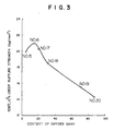
- Fig. 3 is a graph showing a relationship between the 538°; 100 000 n creep rupture strength and oxygen.
- a superior creep rupture strength not less than about 118 N/mm 2 (12 kgf/mm 2 ) can be obtained by making O 2 to a level not more than 100 ppm
- a superior creep rupture strength not less than 147 N/mm 2 (15 kgf/mm 2 ) can be obtained by making O 2 level thereof be not more than 80 ppm
- a superior creep rupture strength not less than 176 N/mm 2 (18 kgf/mm 2 ) can be obtained by making O 2 level thereof be not more than 40 ppm.
- Fig 4 is a graph showing a relationship between 538°C, 10 5 hour creep rupture strength and an amount of Ni. As shown in Fig 4, the creep rupture strength is abruptly lowered as an amount of Ni is increased.
- a creep rupture strength not less than about 108 N/mm 2 (11 kgf/mm 2 ) is exhibited when an amount of Ni is not more-than about 2%, and in particular, a creep rupture strength not less than about 118 N/mm 2 (12 kgf/mm 2 ) is exhibited when an amount of Ni is not more than 1.9%.
- Fig 5 is a graph showing a relationship between an impact absorption energy and an amount of Ni after the specimens have been heated at 500°C for 3,000 hours.
- the specimens of the present invention in which a ratio (Si + Mn)/Ni is not more than 0.18 or in which another ratio Mn/Ni is not more than 0.1 can bring about high impact absorption energy by the increase in an amount of Ni, but the comparative specimens Nos. 12 to 14 in which a ratio (Si + Mn)/Ni exceeds 0.18 or in which another ratio Mn/Ni exceeds 0.12 have a low impact absorption energy not more than 2.4 kgf-m, and thus an increase in the amount of Ni is little concerned with the impact absorption energy.
- Fig 6 is a graph showing a relationship between impact absorption energy after being subjected to heating embrittlement and an amount of Mn or an amount of Si + Mn of the specimens containing 1.6 to 1.9% of Ni.
- Mn or (Si + Mn) greatly influences the impact absorption energy at a particular amount of Ni. That is, the specimens have a very high impact absorption energy when an amount of Mn is not more than 0.2% or an amount of Si + Mn is not more than 0.25%.
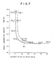
- Fig. 7 is a graph showing a relationship between an impact absorption energy and a ratio Mn/Ni or a ratio (Si + Mn)/Ni of the specimens containing 1.52 to 2.0% Ni. As shown in Fig. 7, a high impact absorption energy not less than 2.5kgf-m is exhibited when a ratio Mn/Ni is not more than 0.12 or a ratio Si + Mn/Ni is not more than 0.18.
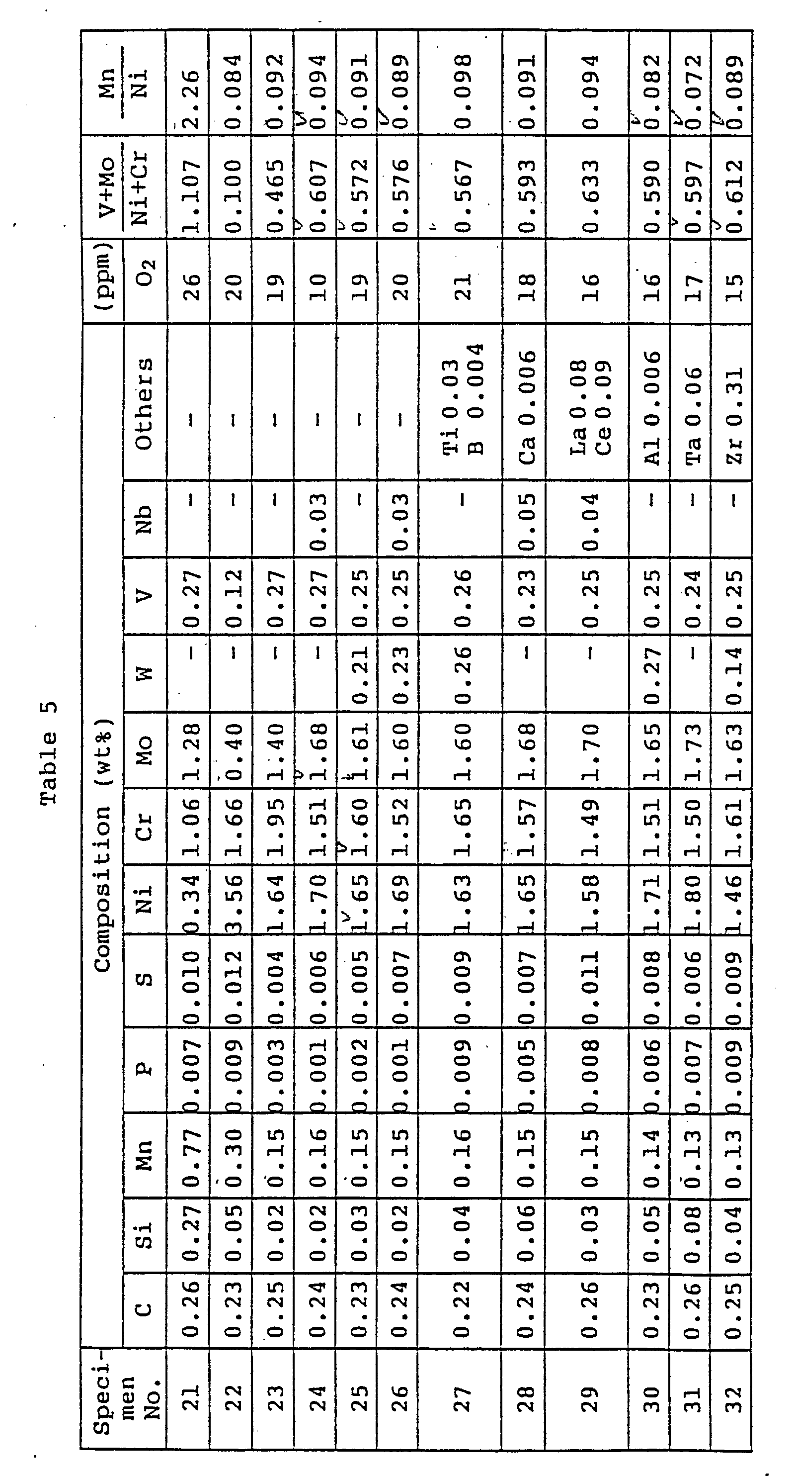
- Table 5 shows typical chemical compositions (wt%) of specimens used in an experiment.
- the specimens were obtained in such a manner that they were melted in a high frequency melting furnace, made to an ingot, and hot forged to a size of 30 mm square at a temperature from 850 to 1250°C.
- the specimens Nos. 21 and 22 were prepared for the comparison with the invented materials.
- the specimens Nos. 23 to 32 are rotor materials superior in toughness according to the present invention.
- the specimens Nos. 23 to 32 were quenched in such a manner that they were austenitized being heated to 950°C in accordance with a simulation of the conditions of the center of a rotor shaft integrating high and low pressure portions of a steam turbine, and then cooled at a speed of 100°C/h. Next, they were annealed by being heated at 650°C for 50 hours and cooled in a furnace.
- the Ni-Cr-Mo-V steel according to the invention included no ferrite phase and was made to have a bainite structure as a whole.
- An austenitizing temperature of the invented steels must be 900 to 1000°C. When the temperature was less than 900°C, creep rupture strength was lowered, although superior toughness can be obtained. When the temperature exceeded 1000°C, toughness was lowered, although superior creep rapture strength was obtained.
- An annealing temperature must be 630 to 700°C. If the temperature is less than 630°C superior toughness cannot be obtained, and when it exceeds 700°C, superior creep strength cannot be obtained.
- Table 6 shows the results of a tensile strength test, impact test, and creep rupture test. Toughness is shown by Charpy impact absorbing energy of a V-shaped notch tested at 20°C and 50% fracture transition temperature (FATT).
- the creep rupture test by a notch was effected using specimens each having a notch bottom radius of 66 mm, a notch outside diameter of 9 mm, and a V-shaped notch configuration of 45° (a radius of a notch bottom end) "r" is 0.16 mm).
- Creep rupture strength is determined by a Larson Mirror method and shown by strength obtained when a specimen was heated at 538°C for 10 5 hours.
- the invented materials have a tensile strength not less than 863 N/mm 2 (88 kgf/mm 2 ) at a room temperature, an impact absorbing energy not less than 49 N/mm 2 (5 kgf/mm 2 ), a 50% FATT not more than 40°C, and a creep rupture strength of 167 N/mm 2 (17 kgf/mm 2 ), and thus they are very useful for a turbine rotor integrating high and low pressure portions.
- These invented steels have greatly improved toughness as compared with that of the material (specimen No. 21) corresponding to a material currently used to a high pressure rotor (having a high impact absorbing energy and a low FATT). Further, they have a 538°C, 10 5 hour notch creep rupture strength superior to that of the material (specimen No. 22) corresponding to a material currently used to a low pressure rotor.
- the creep rupture strength is increased as the component ratio (V + Mo)/(Ni + Cr) is increased until it becomes about 0.7.
- the impact absorbing energy is lowered as the component ratio is increased.
- the toughness vE20 > 2.5 kgf-m and the creep rupture strength R > 108 N/mm 2 (11 kgf/mm 2 ) necessary as the turbine rotor integrating high and low pressure portions are obtained when (V + Mo)/(Ni + Cr) is made to be in the range of 0.45 to 0.7. Further, to examine brittle characteristics of the invented materials and the comparative material No.
- an addition of the rare earth elements is effective to improve the toughness.
- a material added with Y in addition to La - Ce was also examined and it was confirmed that Y was very effective to improve the toughness.
- a superior strength not less than about 118 N/mm 2 (12 kgf/mm 2 ) can be obtained by making O 2 to be in a level not more than 100 ppm, further, a superior strength not less than 147 N/mm 2 (15 kgf/mm 2 ) can be obtained at a level thereof not more than 80 ppm, and, furthermore, a superior strength not less than 177 N/mm 2 (18 kgf/mm 2 ) can be obtained at a level thereof not more than 40 ppm.
- Fig. 1 shows a partial cross sectional view of a steam turbine integrating high and low pressure portions .
- a conventional steam turbine consumes high pressure and temperature steam of 80 at and 480°C at the main steam inlet thereof and low temperature and pressure steam of 722 mmHg and 33°C at the exhaust portion thereof by a single rotor thereof, whereas the steam turbine integrating high and low pressure portions of the invention can increase an output of a single turbine by increasing a pressure and temperature of steam at the main steam inlet thereof to 100 at and 536°C, respectively.
- To increase an output of the single turbine it is necessary to increase a blade length of movable blades at a final stage and to increase a flow rate of steam.
- an ring-shaped band area is increased by about 1.7 times. Consequently, a conventional output of 100 MW is increased to 170 MW, and further when a blade length is increase to 1016 mm, an output per a single turbine can be increased by 2 times or more.
- tangential stress in a low temperature region in particular, tangential stress occurring at the center hole of the turbine rotor at a final stage movable blade portion is about 0.95 in a stress ratio (operating stress/allowable stress) when the rotor is rotated at a rated speed, and in the case of a long blade of 850 mm, the tangential stress is about 1.1 in the stress ratio, so that the above steel is intolerable to this application.
- Ni-Cr-Mo-V steel when 3.5% Ni-Cr-Mo-V steel is used as a rotor material, the above stress ratio thereof is about 0.96 even when long blades of 850 mm are used, because this material has toughness in the low temperature region, and tensile strength and yield strength which are 14% higher than those of the Cr-Mo-V steel.
- the above stress ratio is 1.07, and thus this rotor material is intolerable to this application. Since this material has creep rupture stress in the high temperature region which is about 0.3 times that of the CR-Mo-V steel and thus it is intolerable to this application due to lack of high temperature strength.
- a material of a steam turbine rotor integrating high and low pressure portions on, which long blades not less than 762 mm are attached must have a 538°C, 10 5 h creep rupture strength not less than 147 N/mm 2 (15 kgf/mm 2 ) from a view point of securing safety against high temperature breakdown on a high pressure side, and an impact absorbing energy not less than 2.5 kgfm from a view point of securing safety against breakdown due to brittleness on a low pressure side.
- the steam turbine shown in Figure 1 includes thirteen stages of blades 4 planted on a rotor shaft 3 integrating high and low pressure portions, and steam having a high temperature and pressure of 538°C and 88 at, respectively, is supplied from a steam inlet 1 through a steam control valve 5.
- the steam flows in one direction from the inlet 1 with the temperature and pressure thereof being decreased to 33°C and 722 mm Hg, respectively and then discharged from an outlet 2 through final stage blades 4.
- forged steel composed of Ni-Cr-Mo-V low alloy steel having the characteristics describedin the example 1 is used.
- the portions of the rotor shaft 3 where the blades 4 are planted are formed to a disk shape by integrally machining the rotor shaft 3. The shorter the blade is, the longer the disk portion, whereby the vibration thereof is reduced.
- the rotor shaft 3 according to claim 3 of the according to the present invention was manufactured in such a manner that cast ingot having the alloy compositions of the specimen No. 16 shown in the example 1 and the specimen No. 24 shown in the example 2, respectively was electro-slug remelted, forged to a shaft having a diameter of 1.2 m, heated at 950°C for 10 hours, and then the shaft was cooled at a cooling speed of 100°C/h by spraying water while the it is rotated. Next, the shaft was annealed by being heated at 665°C for 40 hours.
- a test piece cut from the center of the rotor shaft was subjected to a creep test, an impact test of a V-shaped notch (a cross sectional area of the specimen: 0.8 cm 2 ) before the specimen was heated and after it had been heated (after it had been heated at 500°C for 300 hours), and a tensile strength test, and values substantially similar to those of the examples 1 and 2 were obtained.
- Each portion of the present examples are fabricated from a material having the following composition.
- the rotor shaft integrating high and low pressure portions according to the present invention was also able to be applied to a single flow type steam turbine in which a part of steam of an intermediate pressure portion of a rotor shaft was used as a heat source for a heater and the like.
- the materials used in the example 3 were used regarding the rotor shaft.
Landscapes
- Engineering & Computer Science (AREA)
- Chemical & Material Sciences (AREA)
- Mechanical Engineering (AREA)
- General Engineering & Computer Science (AREA)
- Materials Engineering (AREA)
- Metallurgy (AREA)
- Organic Chemistry (AREA)
- Physics & Mathematics (AREA)
- Thermal Sciences (AREA)
- Architecture (AREA)
- Crystallography & Structural Chemistry (AREA)
- Fluid Mechanics (AREA)
- Turbine Rotor Nozzle Sealing (AREA)
Description
- The invention relates to a heat resisting Ni-Cr-Mo-V low alloy steel having superior high temperature strength and toughness.
- In general, Cr-Mo-V steel specified in accordance with ASTM (Designation: A470-84, Class 8) is used as a material of a high pressure rotor exposed to high temperature steam (steam temperature: about 538°C) and 3.5 Ni-Cr-Mo-V steel specified in accordance with ASTM (Designation: A470-84, Class 7) is used as a material of a low pressure (steam temperature: about 100°C) rotor. The former Cr-Mo-V steel is superior in high temperature strength, but inferior in low temperature toughness. The latter 3.5 Ni-Cr-Mo-V steel is superior in low temperature toughness, but inferior in high temperature strength.
- A turbine having a large capacity comprises a high pressure portion, an intermediate pressure portion, and a low pressure portion in accordance with the steam conditions thereof, and high and intermediate pressure rotors are fabricated from Cr-Mo-V steel and a low pressure rotor is fabricated from 3.5 Ni-Cr-Mo-V steel.
- Turbines having a small capacity less than 100,000 and an intermediate capacity of 100,000 to 300,000 KW have a rotor small in size and thus if a material having both the advantages of the above materials used in the high and low pressure rotors is available, the high and the low pressure portions thereof can be integrated (fabricated from the same material). This integration makes the turbine compact as a whole and the cost thereof is greatly reduced. Examples of materials of the rotor integrating high and low pressure portions are disclosed in the JP-B 58-11504, the JP-A 54-40225 and the JP-A 60-224766.
- If the high and low pressure portions are integrated by using the currently available rotor materials, i.e., Cr-Mo-V steel or Ni-Cr-Mo-V steel, the former cannot provide safety against the brittle fracture of the low pressure portion, because it is inferior in low temperature toughness, while the latter cannot provide safety against the creep fracture of the high pressure portion because it is inferior in high temperature strength.
- The JP-B. 58-11504 discloses a rotor integrating high and low pressure portions fabricated from a material consisting, by weight, of 0.15 to 0.3% C, not more than 0.1% Si, not more than 1.0% Mn, 0.5 to 1.5% Cr, 0.5 to 1.5% Ni, not more than 1.5% but more than 0.5% Mo, 0.15 to 0.30% V, 0.01 to 0.1% Nb, and the balance Fe, but it does not exhibit sufficient toughness after heated at a high temperature for a long time and thus long blades having a length not less than 762 mm cannot be planted thereon.
- The JP-A 60-224766 discloses a steam turbine rotor fabricated from a material consisting, by weight, of 0.10 to 0.35% C, not more than 0.10% Si, not more than 1.0% Mn, 1.5 to 2.5% Ni, 1.5 to 3.0% Cr, 0.3 to 1.5% Mo, 0.05 to 0.25% V, and the balance Fe, and further discloses that this material may contain 0.01 to 0.1% Nb, and 0.02 to 0.1% N. This rotor, however, is inferior in creep rupture strength.
- The JP-A 62-189301 discloses a steam turbine integrating high and low pressure portions, which, however, uses a rotor shaft fabricated by mechanically combining a material superior in high temperature strength but inferior in toughness and a material superior in toughness but inferior in high temperature strength, and thus it is not fabricated from a material having the same component. This mechanical combination requires a large structure to obtain strength and thus the rotor shaft cannot be made small in size and, in addition, the reliability is impaired.
- An object of the invention is to provide a heat resisting steel having superior high temperature strength and less heating embrittlement.
- A heat resisting Ni-Cr-Mo-V low alloy steel according to the invention having superior high temperature strength and toughness and less heating embrittlement is defined in
claim 1. - A steam turbine rotor shaft according to
claim 3 is fabricated from said Ni-Cr-Mo-V low alloy steel. The temperature at the steam inlet of the steam turbine is not less than 530°C and the temperature of the steam outlet thereof is not more than 100°C. At least the blades provided at the final stage thereof have a length not less than 762 mm. The rotor shaft is provided at the center thereof with FATT of a temperature not more than the steam outlet temperature and has a 100,000 hour creep rupture strength not less than 108 N/mm2 (11 kg /mm2), more preferably not less than 118 N/mm2 (12 kg /mm2), at a temperature not more than the above steam inlet temperature at 538°C, and a V-shaped notch impact value of not less than 3.0 kgf. m/cm2 after the rotor shaft has been heated at 500°C for 1,000 hours. (1 U8fm = 1Kpm = 9.81 Nm = 9.817) - In the heat resisting Ni-Cr-Mo-V low alloy steel of the invention the ratio (V + Mo)/(Ni + Cr) is 0.45 to 0.7, and also a rotor shaft integrating high and low pressure portions which rotor shaft is made of said Ni-Cr-Mo-V low ally steel.
- The heat resisting Ni-Cr-Mo-V low alloy steels of the invention can comprise at least one element selected from the group consisting of 0.005 to 0.15% Nb, 0.005 to 0.15% Ta, 0.001 to 0.1% Al, 0.001 to 0.1% Zr, 0.001 to 0.1% Ca, 0.001 to 0.1% rare earth elements, 0.1 to 1.0% W, 0.001 to 0.1% Ti, 0.001 to 0.1% B, wherein a ratio (V + Mo)/(Ni + Cr) is 0.45 to 0.7.
- Rotor shafts made of this alloy steel are applied to a steam turbine, according to the present invention.
- Further, an amount of oxygen contained in the above Ni-Cr-Mo-V low alloy steels is preferably not more than 100 ppm as said out in
claim 2. - A method of manufacturing the Ni-Cr-Mo-V steel having the composition described above comprises the steps of forming a steel ingot thereof particularly by melting the ingot by electroremelting or in an arc furnace under an atmospheric air and then by deoxidizing the same through carbon under vacuum, hot forging the steel ingot, quenching the steel ingot in such a manner that it is heated to an austenizing temperature and then cooled at a predetermined cooling speed, and annealing the steel ingot, the Ni-Cr-Mo-V steel mainly having a bainite structure.
- Preferably, the quenching temperature is 900 to 1000°C and an annealing temperature is 630 to 700°C.
- The component of the low alloy steel constituting the steam turbine rotor of the present invention and the reason why heat treatment conditions are limited are explained below.
- Carbon is an element necessary to improve quenching ability and to obtain strength. When an amount thereof is not more than 0.15%, sufficient quenching ability cannot be obtained and a soft ferritic structure occurs about the center of the rotor, so that sufficient tensile strength and yield strength can not be obtained. When a content thereof is not less than 0.4%, it reduces toughness. Thus, the carbon is limited to a range from 0.20 to 0.28%.
- Although silicon and manganese are conventionally added as a deoxidizer, a rotor superior in quality can be produced without the addition thereof when a steel making technology such as a vacuum carbon deoxidation method or an electro-slug melting method is used. A content of Si and Mn must be made as low as possible from a view point that the rotor is made brittle when it is operated for a long time, and thus the amounts thereof are limited to not more than 0.1% and 0.5%, respectively, and in particular, Si ≦ 0.05% and Mn ≦ 0.25% are preferable and Mn ≦ 0.15% is more preferable. Mn not less than 0.05% acts as a desulfurizing agent and is necessary to enhance hot workability. Thus, the lower limit of Mn is 0.05%.
- Nickel is indispensable to improve quenching ability and toughness. A content thereof less than 1.5% is not sufficient to obtain an effect for improving toughness. An addition of a large amount thereof exceeding 2.5% lowers creep rupture strength. In particular, the amount thereof is in a range from 1.6 to 2.0%.
- Chromium improves quenching ability, toughness, and strength, and also improves corrosion resistance in steam. A content thereof less than 0.8% is not sufficient to exhibit an effect for improving them, and an addition thereof exceeding 2.5% lowers creep rupture strength. In particular, preferably an content thereof is in a range from 1.2 to 1.9%.
- Molybdenum precipitates fine carbide in crystal grains while an annealing processing is carried out, with a result that it has an effect for improving high temperature strength and preventing embrittlement caused by annealing. A content thereof less than 0.8% is not sufficient to exhibit this effect, and an addition of a large amount thereof exceeding 2.5% reduces toughness. In particular, preferably a content thereof is in a range from 1.2 to 1.5% from a view point of toughness and preferably a content thereof is in a range exceeding 1.5% but not more than 2.0% from a view point of strength.
- Vanadium precipitates fine carbide in crystal grains while an annealing processing is carried out with a result that it has an effect for improving high temperature strength and toughness. A content thereof less than 0.1% is not sufficient to exhibit this effect, but an addition thereof exceeding 0.3% saturates the effect. In particular, therefore the V-content is limited to 0.2-0.3 and is preferably in the pourpe of 0.20% to 0.5%.
- It has been experimentally clarified that the above-mentioned nickel, chromium, vanadium, and molybdenum are greatly concerned with toughness and high temperature strength and act in combination in the invented steel. More specifically, to obtain a material superior in both high temperature strength and low temperature toughness, a ratio of a sum of vanadium and molybdenum, which are carbide creating elements and which have an effect for improving high temperature strength, to a sum of nickel and chromium, which have an effect for improving quenching ability and toughness, preferably satisfies the equation (V + Mo)/(Ni + Cr) = 0.45 to 0.7.
- When low alloy steel composed of the above component is manufactured, an addition of any of rare earth elements, calcium, zirconium, and aluminum improves the toughness thereof. An addition of rare earth elements less than 0.005% is not sufficient to exhibit an effect for improving the toughness, but an addition thereof exceeding 0.4% saturates the effect. Although an addition of a small amount of Ca improves the toughness, an amount thereof less than 0.0005% does not exhibit an effect for improvement, but an addition thereof exceeding 0.01% saturates the effect. An addition of Zr less than 0.01% is not sufficient to exhibit an effect for improving the toughness, but an addition thereof exceeding 0.2% saturates the effect. An addition of Al less than 0.001% is not sufficient to exhibit an effect for improving the toughness, but an addition thereof exceeding 0.02% lowers creep rupture strength.
- Further, oxygen is concerned with high temperature strength, and superior creep rapture strength can be obtained by controlling an amount of O2 in a range from 5 to 25 ppm in the invented steel.
- At least one of niobium and tantalum is added in an amount of 0.005 to 0.15%. A content thereof less than 0.005% is not sufficient to exhibit an effect for improving strength, whereas when a content thereof exceeds 0.15% the huge carbides thereof are crystallized in such a large structure as a steam turbine rotor, whereby strength and toughness are lowered, and thus this content is in a range from 0.005 to 0.15%. In particular, preferably the content is in a range from 0.01 to 0.05%.
- Tungsten is added in an amount not less than 0.1% to increase strength. This amount must be in a range from 0.1 to 1.0%, because when the amount exceeds 1.0%, a problem of segregation arises in a large steel ingot by which strength is lowered, and preferably the amount is in a range from 0.1 to 0.5%.
- A ratio Mn/Ni or a ratio (Si + Mn)/Ni must be not more than 0.12 and not more than 0.18, respectively, whereby Ni-Cr-Mo-V low alloy steel having a bainitic structure is greatly prevented from being subjected to heating embrittlement, with the result that the low alloy steel is applicable to a rotor shaft integrating low and high pressure portions.
- The steel having the characteristics superior in both creep rupture strength and high impact value can be obtained by setting a ratio (V + Mo)/(Ni + Cr) to 0.45 to 0.7, whereby blades each having a length not less than 762 mm can be planted on the rotor shaft integrating high and low pressure portions according to the present invention.
- The application of the above new material to a rotor shaft enables long blades having a length of not less than 762 mm to be planted on the rotor shaft as final stage blades, and the rotor shaft can be made compact such that a ratio (L/D) of a length (L) thereof between bearings to a blade diameter (D), is made to 1.4 to 2.3, and preferably the ratio is made to 1.6 to 2.0. Further, a ratio of the maximum diameter (d) of the rotor shaft to a length (ℓ) of final long blades can be made to 1.5 to 2.0. With this arrangement, an amount of steam can be increased to the maximum thereof in accordance with the characteristics of the rotor shaft, whereby a large amount of power can be generated by a small steam turbine. In particular, preferably this ratio is 1.6 to 1.8. A ratio not less than 1.5 is determined from the number of blades, and the greater the ratio, the better the result can be obtained, but preferably the ratio is not more than 2.0 from a view point of strength with respect to a centrifugal force.
- A steam turbine using the rotor shaft integrating high and low pressure portions according to the present invention is small in size, and capable of generating power of 100,000 to 300,000 KW and making a distance thereof between bearings very short, i.e., not more than 0.8 m per 10, 000 KW of generated power. Preferably, the distance is 0.25 to 0.6 m per 10,000 KW.
- The application of the above Ni-Cr-Mo-V low alloy steel to a rotor shaft integrating high and low pressure portions enables movable blades having a length in particular of not less than 850 mm to be planted at a final stage, whereby an output from a single turbine can be increased and the turbine can be made small in size.
-
- Fig. 1 is a partial cross sectional view of a steam turbine using a rotor shaft integrating high and low pressure portions;
- Fig. 2 is a graph showing a relationship between ratio (V + Mo)/(Ni + Cr), and creep rupture strength and impact absorption energy;
- Fig. 3 is a graph showing a relationship between creep rupture strength and oxygen;
- Fig. 4 is a graph showing a relationship between creep rupture strength and Ni; and
- Fig 5 to 7 are graphs showing relationships between a V-shaped notch impact absorption energy, and Ni, Mn, Si + Mn, a ratio Mn/Ni, and a ratio (Si + Mn)/Ni.
-
- A turbine rotor is described below with reference to examples. Table 1 shows chemical compositions of typical specimens subjected to toughness and creep rapture tests. The specimens were obtained in such a manner that they were melted in a high frequency melting furnace, made to an ingot, and hot forged to a size of 30 mm square at a temperature from 850 to 1150°C. The specimens Nos. 1, 2 and 7 to 11 are materials according to the invention. The specimens Nos. 3 to 6 were prepared for the comparison with the invented materials. The specimen No. 5 is a material corresponding to ASTM A470 Class 8 and the specimen No. 6 is a material corresponding to ASTM A470 Class 7. These specimens were quenched in such a manner that they were made to have austenitic structure by being heated to 950°C in accordance with a simulation of the conditions of the center of a rotor shaft integrating high and low pressure portions of a steam turbine, and then cooled at a speed of 100°C/h. Next, they were annealed by being heated at 665°C for 40 hours and cooled in a furnace. Cr-Mo-V steels according to the invention included no ferrite phase and were made to have a bainite structure as a whole.
- An austenitizing temperature of the invented steels must be 900 to 1000°C. When the temperature is less than 900°C, creep rupture strength is lowered, although superior toughness can be obtained. When the temperature exceeds 1000°C, toughness is lowered, although superior creep rupture strength can be obtained. An annealing temperature must be 630 to 700°C. If the temperature is less than 630°C, superior toughness cannot be obtained, and when it exceeds 700°C, superior creep strength cannot be obtained.
- Table 2 shows the results of a tensile strength test, impact test, and creep rupture test. Toughness is shown by Charpy impact absorbing energy of a V-shaped notch tested at 20°C. Creep rupture strength is determined by Larson Miller method and shown by a strength obtained when a specimen was heated at 538°C for 100,000 hours. As apparent from Table 2, the invented materials have a tensile strength not less than 863 N/mm2 (88 kgf/mm2) at a room temperature, a 0.2% yield strength not less than 687 N/mm2 (70 kgf/mm2), an FATT not more than 40°C, an impact absorbing energy not less than 2.5 kgf-m both before they were heated and after they had been heated, and a creep rapture strength not less than about 108 N/mm2 (11 kg/mm2), and thus they are very useful for a turbine rotor integrating high and low pressure portions. In particular, a material having a strength not less than 147 N/mm2 (15 kg/mm2) is preferable to plant long blades of 850 mm.


- Fig. 2 shows a relationship between a ratio of a sum of V and Mo acting as carbide creating elements to a sum of Ni and Cr acting as quenching ability improving elements, and creep rupture strength and impact absorbing energy. The creep rupture strength σR is increased as the component ratio (V + Mo)/(Ni + Cr) is increased until it becomes about 0.7. It is found that the impact absorbing energy is lowered as the component ratio is increased. It is found that a toughness vE20 ≧ (2.5 kgf·m) and a creep rupture strength σR ≧ 108 N/mm2 (11 kgf/mm2) is necessary as the characteristics of a material forming the turbine rotor integrating high and low pressure portions are obtained when (V + Mo)/(Ni + Cr) = 0.45 to 0.7. Further, to examine the brittle characteristics of the invented material No. 2 and the comparative material Nos. 5 (corresponding to a material currently used to a high pressure rotor) and 6 (corresponding to a material currently used to a low pressure rotor), an impact test was effected to specimens before subjected to a brittle treatment for 3000 h at 500°C and those after subjected to the treatment and a 50% fracture appearance transition temperature (FATT) was examined. An FATT of the comparative material No. 5 was increased (made brittle) from 119°C to 135°C (ΔFATT = 16°C), an FATT of the material No. 6 was increased from -20°C to 18°C (ΔFATT = 38°C) by the brittle treatment, whereas it was also confirmed that an FATT of the invented material No. 3 remained at 38°C before and after the brittle treatment and thus it was confirmed that this material was not made brittle.
- The specimens Nos. 8 to 11 of the invented materials added with rare earth elements (La - Ce), Ca, Zr, and Al, respectively, have toughness improved by these rare earth elements. In particular, the addition of the rare earth elements is effective to improve the toughness. A material added with Y in addition to La - Ce was also examined and it was confirmed that Y was very effective to improve the toughness.
- Table 3 shows the chemical compositions and creep rapture strength of the specimens prepared to examine an influence of oxygen to creep rapture strength of the invented materials. A method of melting and forging these specimens were the same as that of the above-mentioned specimens Nos. 1 to 11.

- The specimens were quenched in such a manner that they were austenitized by being heated to 950°C and then by being cooled at a speed of 100°C/h. Next, they were annealed by being heated at 660°C for 40 hours. Table 4 shows 538°C creep rapture strength in the same manner as that shown in Table 2. Fig. 3 is a graph showing a relationship between the 538°; 100 000 n creep rupture strength and oxygen. It is found that a superior creep rupture strength not less than about 118 N/mm2 (12 kgf/mm2) can be obtained by making O2 to a level not more than 100 ppm, further, a superior creep rupture strength not less than 147 N/mm2 (15 kgf/mm2) can be obtained by making O2 level thereof be not more than 80 ppm, and furthermore, a superior creep rupture strength not less than 176 N/mm2 (18 kgf/mm2) can be obtained by making O2 level thereof be not more than 40 ppm.
Specimen No. Mn / Ni Si+Mn / Ni V+Mo / Ni+Cr Creep rupture strength
(kgf/mm2) (9,81 N/mm2)15 0.047 0.076 0.55 19.9 16 0.063 0.088 0.57 21.0 17 0.056 0.087 0.56 20.3 18 0.073 0.103 0.57 18.5 19 0.065 0.089 0.51 15.6 20 0.052 0.087 0.52 14.3 - Fig 5 is a graph showing a relationship between an impact absorption energy and an amount of Ni after the specimens have been heated at 500°C for 3,000 hours. As shown in Fig 5, the specimens of the present invention in which a ratio (Si + Mn)/Ni is not more than 0.18 or in which another ratio Mn/Ni is not more than 0.1 can bring about high impact absorption energy by the increase in an amount of Ni, but the comparative specimens Nos. 12 to 14 in which a ratio (Si + Mn)/Ni exceeds 0.18 or in which another ratio Mn/Ni exceeds 0.12 have a low impact absorption energy not more than 2.4 kgf-m, and thus an increase in the amount of Ni is little concerned with the impact absorption energy.
- Likewise, Fig 6 is a graph showing a relationship between impact absorption energy after being subjected to heating embrittlement and an amount of Mn or an amount of Si + Mn of the specimens containing 1.6 to 1.9% of Ni. As shown in Fig 6, it is apparent that Mn or (Si + Mn) greatly influences the impact absorption energy at a particular amount of Ni. That is, the specimens have a very high impact absorption energy when an amount of Mn is not more than 0.2% or an amount of Si + Mn is not more than 0.25%.
- Likewise, Fig. 7 is a graph showing a relationship between an impact absorption energy and a ratio Mn/Ni or a ratio (Si + Mn)/Ni of the specimens containing 1.52 to 2.0% Ni. As shown in Fig. 7, a high impact absorption energy not less than 2.5kgf-m is exhibited when a ratio Mn/Ni is not more than 0.12 or a ratio Si + Mn/Ni is not more than 0.18.
- Table 5 shows typical chemical compositions (wt%) of specimens used in an experiment.
- The specimens were obtained in such a manner that they were melted in a high frequency melting furnace, made to an ingot, and hot forged to a size of 30 mm square at a temperature from 850 to 1250°C. The specimens Nos. 21 and 22 were prepared for the comparison with the invented materials. The specimens Nos. 23 to 32 are rotor materials superior in toughness according to the present invention.
- The specimens Nos. 23 to 32 were quenched in such a manner that they were austenitized being heated to 950°C in accordance with a simulation of the conditions of the center of a rotor shaft integrating high and low pressure portions of a steam turbine, and then cooled at a speed of 100°C/h. Next, they were annealed by being heated at 650°C for 50 hours and cooled in a furnace. The Ni-Cr-Mo-V steel according to the invention included no ferrite phase and was made to have a bainite structure as a whole.
- An austenitizing temperature of the invented steels must be 900 to 1000°C. When the temperature was less than 900°C, creep rupture strength was lowered, although superior toughness can be obtained. When the temperature exceeded 1000°C, toughness was lowered, although superior creep rapture strength was obtained. An annealing temperature must be 630 to 700°C. If the temperature is less than 630°C superior toughness cannot be obtained, and when it exceeds 700°C, superior creep strength cannot be obtained.
- Table 6 shows the results of a tensile strength test, impact test, and creep rupture test. Toughness is shown by Charpy impact absorbing energy of a V-shaped notch tested at 20°C and 50% fracture transition temperature (FATT).
- The creep rupture test by a notch was effected using specimens each having a notch bottom radius of 66 mm, a notch outside diameter of 9 mm, and a V-shaped notch configuration of 45° (a radius of a notch bottom end) "r" is 0.16 mm).

- Creep rupture strength is determined by a Larson Mirror method and shown by strength obtained when a specimen was heated at 538°C for 105 hours. As apparent from Table 6, the invented materials have a tensile strength not less than 863 N/mm2 (88 kgf/mm2) at a room temperature, an impact absorbing energy not less than 49 N/mm2 (5 kgf/mm2), a 50% FATT not more than 40°C, and a creep rupture strength of 167 N/mm2 (17 kgf/mm2), and thus they are very useful for a turbine rotor integrating high and low pressure portions.
- These invented steels have greatly improved toughness as compared with that of the material (specimen No. 21) corresponding to a material currently used to a high pressure rotor (having a high impact absorbing energy and a low FATT). Further, they have a 538°C, 105 hour notch creep rupture strength superior to that of the material (specimen No. 22) corresponding to a material currently used to a low pressure rotor.
- In the relationship between a ratio of a sum of V and Mo as carbide creating elements to a sum of Ni and Cr as quenching ability improving elements, and creep rupture strength and impact absorbing energy, the creep rupture strength is increased as the component ratio (V + Mo)/(Ni + Cr) is increased until it becomes about 0.7. The impact absorbing energy is lowered as the component ratio is increased. The toughness vE20 > 2.5 kgf-m and the creep rupture strength R > 108 N/mm2 (11 kgf/mm2) necessary as the turbine rotor integrating high and low pressure portions are obtained when (V + Mo)/(Ni + Cr) is made to be in the range of 0.45 to 0.7. Further, to examine brittle characteristics of the invented materials and the comparative material No. 21 (corresponding to a material currently used to a high pressure rotor) and the comparative material No. 22 (corresponding to a material currently used to a low pressure rotor), an impact test was effected to specimens before subjected to a brittle treatment at 500°C for 3000 h and those after subjected to the treatment and a 50% fracture transition temperature (FATT) was examined. As a result, an FATT of the comparative material No. 21 was increased (made brittle) from 119°C to 135°C (ΔFATT = 16°C), an FATT of the material, No. 2 was increased from -20°C to 18°C (ΔFATT = 38°C) by the brittle treatment, whereas it was also confirmed that an FATT of the invented materials were 39°C both before and after subjected to the brittle treatment and thus it was confirmed that they were not made brittle.
- The specimens Nos. 27 to 32 of the invented materials added with rare earth elements (La - Ce), Ca, Zr, and Al, respectively, have toughness improved thereby. In particular, an addition of the rare earth elements is effective to improve the toughness. A material added with Y in addition to La - Ce was also examined and it was confirmed that Y was very effective to improve the toughness.
- As a result of an examination of an influence of oxygen to creep rupture strength of the invented materials, it is found that a superior strength not less than about 118 N/mm2 (12 kgf/mm2) can be obtained by making O2 to be in a level not more than 100 ppm, further, a superior strength not less than 147 N/mm2 (15 kgf/mm2) can be obtained at a level thereof not more than 80 ppm, and, furthermore, a superior strength not less than 177 N/mm2 (18 kgf/mm2) can be obtained at a level thereof not more than 40 ppm.
- As a result of an examination of the relationship between 538°C, 105 hour creep rupture strength and an amount of Ni, it is found that the creep rupture strength is abruptly lowered as an amount of Ni is increased. In particular, a strength not less than about 108 N/mm2 (11 kgf/mm2) is exhibited when an amount of Ni is not more than about 2%, and in particular, a strength not less than about 118 N/mm2 (12 kgf/mm2) is exhibited when an amount of Ni is not more than 1.9%.
- Further, as a result of an examination of a relationship between impact value and an amount of Ni after the specimens have been heated at 500°C for 3000 hours, the specimens according to the present invention in which the ratio (Si + Mn)/Ni is not more than 0.18 bring about high impact values by the increase in an amount of Ni, but the comparative specimens in which the ratio (Si + Mn)/Ni exceeds 0.18 have a low impact value not more than 23.5 N/mm2 (2.4 kgf/mm2) and thus an increase in the amount of Ni is little concerned with the impacts value.
- As a result of an examination of a relationship between impact value and an amount of Mn or an amount of Si + Mn of the specimens containing 1.6 to 1.9% of Ni, it is found that Mn or Si + Mn greatly influences the impact value at a particular amount of Ni, and the specimens have a very high impact value when an amount of Mn is not more than 0.2% or an amount of Si + Mn is in a range from 0.07 to 0.25%.
- As a result of an examination of a relationship between impact value and a ratio Mn/Ni or a ratio (Si + Mn)/Ni of the specimens containing 1.52 to 2.0% of Ni, a high impact value not less than 25 N/mm2 (2.5 kgf/mm2) is exhibited when the ratio Mn/Ni is not more than 0.12 or the ratio (Si + Mn)/Ni is in a range from 0.04 to 0.18.
- Fig. 1 shows a partial cross sectional view of a steam turbine integrating high and low pressure portions . A conventional steam turbine consumes high pressure and temperature steam of 80 at and 480°C at the main steam inlet thereof and low temperature and pressure steam of 722 mmHg and 33°C at the exhaust portion thereof by a single rotor thereof, whereas the steam turbine integrating high and low pressure portions of the invention can increase an output of a single turbine by increasing a pressure and temperature of steam at the main steam inlet thereof to 100 at and 536°C, respectively. To increase an output of the single turbine, it is necessary to increase a blade length of movable blades at a final stage and to increase a flow rate of steam. For example, when a blade length of the movable blade at a final stage is increased from 660 to 850 mm, an ring-shaped band area is increased by about 1.7 times. Consequently, a conventional output of 100 MW is increased to 170 MW, and further when a blade length is increase to 1016 mm, an output per a single turbine can be increased by 2 times or more.
- When a Cr-Mo-V steel containing 0.5% of Ni is used for a rotor integrating high and low pressure "portions as a material of the rotor shaft having blades of a length not less than 850 mm, this rotor material can sufficiently withstand an increase in a steam pressure and temperature at the main stream inlet thereof, because this steel is superior in high temperature strength and creep characteristics to be thereby used at a high temperature region. In the case of a long blade of 660 mm, however, tangential stress in a low temperature region, in particular, tangential stress occurring at the center hole of the turbine rotor at a final stage movable blade portion is about 0.95 in a stress ratio (operating stress/allowable stress) when the rotor is rotated at a rated speed, and in the case of a long blade of 850 mm, the tangential stress is about 1.1 in the stress ratio, so that the above steel is intolerable to this application.
- On the other hand, when 3.5% Ni-Cr-Mo-V steel is used as a rotor material, the above stress ratio thereof is about 0.96 even when long blades of 850 mm are used, because this material has toughness in the low temperature region, and tensile strength and yield strength which are 14% higher than those of the Cr-Mo-V steel. However, if longer blades of 1016 mm are used, the above stress ratio is 1.07, and thus this rotor material is intolerable to this application. Since this material has creep rupture stress in the high temperature region which is about 0.3 times that of the CR-Mo-V steel and thus it is intolerable to this application due to lack of high temperature strength.
- To increase an output as described above, it is necessary to provide a rotor material which simultaneously has both superior characteristics of the Cr-Mo-V steel in a high temperature region and superior characteristics of the Ni-Cr-Mo-V steel in a low temperature region.
- When a long blade of a class from 762 to 1016 mm is used, a material having a tensile strength not less than 863 N/mm2 (88 kgf/mm2) is necessary, because conventional Ni-Cr-Mo-V steel (ASTM A470 Class 7) has the stress ratio of 1.07, as described above.
- Further, a material of a steam turbine rotor integrating high and low pressure portions on, which long blades not less than 762 mm are attached must have a 538°C, 105 h creep rupture strength not less than 147 N/mm2 (15 kgf/mm2) from a view point of securing safety against high temperature breakdown on a high pressure side, and an impact absorbing energy not less than 2.5 kgfm from a view point of securing safety against breakdown due to brittleness on a low pressure side.
- From the above view point, in the invention there was obtained heat resisting steels which can satisfy the above requirements and which increase an output per a single turbine.
- The steam turbine shown in Figure 1 includes thirteen stages of
blades 4 planted on arotor shaft 3 integrating high and low pressure portions, and steam having a high temperature and pressure of 538°C and 88 at, respectively, is supplied from asteam inlet 1 through asteam control valve 5. The steam flows in one direction from theinlet 1 with the temperature and pressure thereof being decreased to 33°C and 722 mm Hg, respectively and then discharged from anoutlet 2 throughfinal stage blades 4. Since therotor shaft 3 integrating high and low pressure portions is exposed to a steam temperature ranging from 538°C to 33°C, forged steel composed of Ni-Cr-Mo-V low alloy steel having the characteristics describedin the example 1 is used. The portions of therotor shaft 3 where theblades 4 are planted are formed to a disk shape by integrally machining therotor shaft 3. The shorter the blade is, the longer the disk portion, whereby the vibration thereof is reduced. - The
rotor shaft 3 according toclaim 3 of the according to the present invention, was manufactured in such a manner that cast ingot having the alloy compositions of the specimen No. 16 shown in the example 1 and the specimen No. 24 shown in the example 2, respectively was electro-slug remelted, forged to a shaft having a diameter of 1.2 m, heated at 950°C for 10 hours, and then the shaft was cooled at a cooling speed of 100°C/h by spraying water while the it is rotated. Next, the shaft was annealed by being heated at 665°C for 40 hours. A test piece cut from the center of the rotor shaft was subjected to a creep test, an impact test of a V-shaped notch (a cross sectional area of the specimen: 0.8 cm2) before the specimen was heated and after it had been heated (after it had been heated at 500°C for 300 hours), and a tensile strength test, and values substantially similar to those of the examples 1 and 2 were obtained. - Each portion of the present examples are fabricated from a material having the following composition.
- The rotor shaft integrating high and low pressure portions according to the present invention was also able to be applied to a single flow type steam turbine in which a part of steam of an intermediate pressure portion of a rotor shaft was used as a heat source for a heater and the like. The materials used in the example 3 were used regarding the rotor shaft.
Claims (3)
- Heat resisting Ni-Cr-Mo-V low alloy steel having a bainitic structure and consisting of, in weight-%,optionally:0.20 to 0.28 % carbon≤ 0.10 % silicon0.05 to 0.25 % manganese1.6 to 2.0 % nickel1.2 to 2.5 % chromium1.2 to 2.0 % molybdenum0.2 to 0.3 % vanadiuma ratio Mn/Ni ≤ 0.12 and/ora ratio (Mn+Si)/Ni ≤ 0.18, anda ratio (V + Mo)/(Ni + Cr) = 0.45 to 0.7,the balance being iron and incidental impurities.0.001 to 0.1 % in total of at least one element selected from the group consisting of titanium, boron, aluminium, zirconium, calcium and rare earth elements,0.005 to 0.15 % of at least one element selected from the group consisting of niobium and tantalum,0.1 to 1.0 % tungsten,
- Alloy steel according to claim 1, comprising not
more than 100 ppm oxygen. - Rotor shaft of a steam turbine consisting of the heat resisting Ni-Cr-Mo-V low alloy steel according to claim 1 or 2.
Applications Claiming Priority (7)
| Application Number | Priority Date | Filing Date | Title |
|---|---|---|---|
| JP2389089 | 1989-02-03 | ||
| JP2389089 | 1989-02-03 | ||
| JP23890/89 | 1989-02-03 | ||
| JP12662289 | 1989-05-22 | ||
| JP126622/89 | 1989-05-22 | ||
| JP12662289 | 1989-05-22 | ||
| EP19900102007 EP0384181B1 (en) | 1989-02-03 | 1990-02-01 | Steam turbine |
Related Parent Applications (2)
| Application Number | Title | Priority Date | Filing Date |
|---|---|---|---|
| EP90102007.3 Division | 1990-02-01 | ||
| EP19900102007 Division EP0384181B1 (en) | 1989-02-03 | 1990-02-01 | Steam turbine |
Publications (2)
| Publication Number | Publication Date |
|---|---|
| EP0761836A1 EP0761836A1 (en) | 1997-03-12 |
| EP0761836B1 true EP0761836B1 (en) | 2003-10-01 |
Family
ID=26361328
Family Applications (3)
| Application Number | Title | Priority Date | Filing Date |
|---|---|---|---|
| EP96115660A Expired - Lifetime EP0761836B1 (en) | 1989-02-03 | 1990-02-01 | Heat resisting steel and turbine rotor |
| EP98101285A Expired - Lifetime EP0849434B8 (en) | 1989-02-03 | 1990-02-01 | Combined generator system |
| EP19900102007 Expired - Lifetime EP0384181B1 (en) | 1989-02-03 | 1990-02-01 | Steam turbine |
Family Applications After (2)
| Application Number | Title | Priority Date | Filing Date |
|---|---|---|---|
| EP98101285A Expired - Lifetime EP0849434B8 (en) | 1989-02-03 | 1990-02-01 | Combined generator system |
| EP19900102007 Expired - Lifetime EP0384181B1 (en) | 1989-02-03 | 1990-02-01 | Steam turbine |
Country Status (5)
| Country | Link |
|---|---|
| EP (3) | EP0761836B1 (en) |
| JP (1) | JP3247676B2 (en) |
| AU (1) | AU628916B2 (en) |
| CA (1) | CA2009120C (en) |
| DE (3) | DE69034188T2 (en) |
Families Citing this family (19)
| Publication number | Priority date | Publication date | Assignee | Title |
|---|---|---|---|---|
| JP3315800B2 (en) * | 1994-02-22 | 2002-08-19 | 株式会社日立製作所 | Steam turbine power plant and steam turbine |
| JP3461945B2 (en) * | 1994-12-26 | 2003-10-27 | 株式会社日本製鋼所 | Method of manufacturing high-low pressure integrated turbine rotor |
| EP0759499B2 (en) * | 1995-08-21 | 2005-12-14 | Hitachi, Ltd. | Steam-turbine power plant and steam turbine |
| US6129514A (en) * | 1996-02-16 | 2000-10-10 | Hitachi, Ltd. | Steam turbine power-generation plant and steam turbine |
| US6305078B1 (en) | 1996-02-16 | 2001-10-23 | Hitachi, Ltd. | Method of making a turbine blade |
| US6358004B1 (en) | 1996-02-16 | 2002-03-19 | Hitachi, Ltd. | Steam turbine power-generation plant and steam turbine |
| JP3898785B2 (en) * | 1996-09-24 | 2007-03-28 | 株式会社日立製作所 | High and low pressure integrated steam turbine blades, high and low pressure integrated steam turbine, combined power generation system, and combined power plant |
| JPH10265909A (en) * | 1997-03-25 | 1998-10-06 | Toshiba Corp | High toughness heat-resistant steel, turbine rotor and method of manufacturing the same |
| JP2000291403A (en) * | 1999-04-02 | 2000-10-17 | Toshiba Corp | Steam turbine |
| EP1348770A1 (en) * | 2002-03-19 | 2003-10-01 | E.C.O. Trading LLC | Plant and procedure for the production of small parts in hot formed steel |
| JP4597233B2 (en) * | 2008-09-19 | 2010-12-15 | 株式会社日立製作所 | Generator rotor shaft material |
| US9297277B2 (en) | 2011-09-30 | 2016-03-29 | General Electric Company | Power plant |
| RU2477335C1 (en) * | 2011-10-21 | 2013-03-10 | Российская Федерация, от имени которой выступает Министерство промышленности и торговли Российской Федерации (Минпромторг России) | Steel |
| CN108119187B (en) * | 2018-02-11 | 2023-10-17 | 杭州汽轮机股份有限公司 | A low-pressure stage moving blade of an industrial steam turbine with variable speed and large flow rate |
| JP7315454B2 (en) * | 2019-12-25 | 2023-07-26 | 三菱重工業株式会社 | turbine rotor material |
| CN112410619B (en) * | 2020-11-10 | 2022-02-15 | 武汉轻工大学 | A cobalt-based casting alloy modified by adding niobium and nitrogen and its application |
| CN113930666B (en) * | 2021-09-02 | 2022-09-23 | 中铁工程装备集团有限公司 | Preparation method and application of tool apron material for TBM |
| CN113802068B (en) * | 2021-09-18 | 2022-03-04 | 建龙北满特殊钢有限责任公司 | Alloy structural steel containing tungsten and production method thereof |
| CN114892085B (en) * | 2022-05-06 | 2023-03-03 | 鞍钢股份有限公司 | Wide and thick steel plate for advanced nuclear power unit positioning and manufacturing method thereof |
Family Cites Families (12)
| Publication number | Priority date | Publication date | Assignee | Title |
|---|---|---|---|---|
| JPS5440225A (en) | 1977-09-06 | 1979-03-29 | Kobe Steel Ltd | Low alloy steel for rotor shaft |
| JPS5820363B2 (en) * | 1978-06-08 | 1983-04-22 | 株式会社東芝 | steam turbine equipment |
| JPS5811504A (en) * | 1981-07-15 | 1983-01-22 | Toyo Soda Mfg Co Ltd | Scale preventing agent in polymerizing vinyl monomer |
| JPS58117306A (en) * | 1981-12-29 | 1983-07-12 | Hitachi Ltd | Combined plant |
| JPS5996248A (en) * | 1982-11-26 | 1984-06-02 | Toshiba Corp | Integrated high, medium and low pressure rotor for steam turbine and its manufacture |
| JPS60224766A (en) * | 1984-04-23 | 1985-11-09 | Toshiba Corp | Steam turbine rotor |
| JPS61143523A (en) * | 1984-12-17 | 1986-07-01 | Toshiba Corp | Manufacture of rotor for geothermal energy turbine |
| JPS62109949A (en) * | 1985-11-06 | 1987-05-21 | Kobe Steel Ltd | Nicrmo steel having excellent stress corrosion cracking resistance |
| JPS62180030A (en) * | 1986-02-03 | 1987-08-07 | Hitachi Ltd | Turbine moving blade |
| EP0237170B1 (en) * | 1986-02-05 | 1994-05-11 | Hitachi, Ltd. | Heat resistant steel and gas turbine composed of the same |
| JPS62189301A (en) * | 1986-02-14 | 1987-08-19 | Hitachi Ltd | High and low pressure integrated steam turbine rotor |
| JPS63171856A (en) * | 1987-01-09 | 1988-07-15 | Hitachi Ltd | heat resistant steel |
-
1990
- 1990-02-01 EP EP96115660A patent/EP0761836B1/en not_active Expired - Lifetime
- 1990-02-01 DE DE1990634188 patent/DE69034188T2/en not_active Expired - Lifetime
- 1990-02-01 EP EP98101285A patent/EP0849434B8/en not_active Expired - Lifetime
- 1990-02-01 EP EP19900102007 patent/EP0384181B1/en not_active Expired - Lifetime
- 1990-02-01 AU AU49014/90A patent/AU628916B2/en not_active Expired
- 1990-02-01 CA CA002009120A patent/CA2009120C/en not_active Expired - Lifetime
- 1990-02-01 DE DE1990633878 patent/DE69033878T2/en not_active Expired - Lifetime
- 1990-02-01 DE DE1990634106 patent/DE69034106T2/en not_active Expired - Lifetime
-
2000
- 2000-06-16 JP JP2000181358A patent/JP3247676B2/en not_active Expired - Fee Related
Also Published As
| Publication number | Publication date |
|---|---|
| CA2009120A1 (en) | 1990-08-03 |
| AU4901490A (en) | 1990-08-09 |
| EP0849434B8 (en) | 2005-08-10 |
| JP3247676B2 (en) | 2002-01-21 |
| EP0849434B1 (en) | 2005-04-27 |
| EP0849434A3 (en) | 2002-11-06 |
| DE69034106D1 (en) | 2003-11-06 |
| EP0384181A2 (en) | 1990-08-29 |
| AU628916B2 (en) | 1992-09-24 |
| DE69034106T2 (en) | 2004-06-17 |
| EP0384181B1 (en) | 2001-12-19 |
| JP2001026837A (en) | 2001-01-30 |
| EP0761836A1 (en) | 1997-03-12 |
| EP0384181A3 (en) | 1990-12-05 |
| DE69033878D1 (en) | 2002-01-31 |
| EP0849434A2 (en) | 1998-06-24 |
| CA2009120C (en) | 1998-05-12 |
| DE69033878T2 (en) | 2002-06-27 |
| DE69034188D1 (en) | 2005-06-02 |
| DE69034188T2 (en) | 2006-03-09 |
Similar Documents
| Publication | Publication Date | Title |
|---|---|---|
| US6224334B1 (en) | Steam turbine, rotor shaft thereof, and heat resisting steel | |
| EP0867522B1 (en) | High toughness heat-resistant steel, turbine rotor and method of producing the same | |
| EP0237170B1 (en) | Heat resistant steel and gas turbine composed of the same | |
| EP0384181B1 (en) | Steam turbine | |
| KR0175075B1 (en) | Rotor for steam turbine and manufacturing method | |
| EP0384433B1 (en) | Ferritic heat resisting steel having superior high-temperature strength | |
| US4090813A (en) | High-efficiency turbo-machine impellers | |
| JP3354832B2 (en) | High toughness ferritic heat-resistant steel | |
| US5560788A (en) | Heat resisting steels | |
| US4857120A (en) | Heat-resisting steel turbine part | |
| JPS616256A (en) | 12%Cr heat resistant steel | |
| JPS6338420B2 (en) | ||
| JP3106121B2 (en) | Rotor shaft for high and low pressure integrated steam turbine | |
| JPH07118812A (en) | Heat-resistant cast steel turbine casing and manufacturing method thereof | |
| JP3798456B2 (en) | Ferritic heat resistant steel for turbines | |
| JP3662151B2 (en) | Heat-resistant cast steel and heat treatment method thereof | |
| CA2169781C (en) | Rotor shaft for a steam turbine | |
| JP3510606B2 (en) | High and low pressure integrated turbine rotor and method of manufacturing the same | |
| JPH0641678A (en) | Turbine rotor | |
| JPH07216513A (en) | High toughness ferritic heat resistance steel excellent in strength at high temperature | |
| US20240327941A1 (en) | Alloy, raw workpiece, component consisting of austenite, and method for heat-treating an austenite | |
| JPS60110847A (en) | Material for rotor of steam turbine | |
| JPS61221355A (en) | 12Cr heat resistant steel | |
| JPS6360262A (en) | Heat resistant steel | |
| JPH03191038A (en) | Steam turbine rotor |
Legal Events
| Date | Code | Title | Description |
|---|---|---|---|
| PUAI | Public reference made under article 153(3) epc to a published international application that has entered the european phase |
Free format text: ORIGINAL CODE: 0009012 |
|
| AC | Divisional application: reference to earlier application |
Ref document number: 384181 Country of ref document: EP |
|
| AK | Designated contracting states |
Kind code of ref document: A1 Designated state(s): CH DE FR GB LI |
|
| 17P | Request for examination filed |
Effective date: 19970306 |
|
| 17Q | First examination report despatched |
Effective date: 19971031 |
|
| APAB | Appeal dossier modified |
Free format text: ORIGINAL CODE: EPIDOS NOAPE |
|
| APAB | Appeal dossier modified |
Free format text: ORIGINAL CODE: EPIDOS NOAPE |
|
| APAD | Appeal reference recorded |
Free format text: ORIGINAL CODE: EPIDOS REFNE |
|
| APCB | Communication from the board of appeal sent |
Free format text: ORIGINAL CODE: EPIDOS OBAPE |
|
| GRAH | Despatch of communication of intention to grant a patent |
Free format text: ORIGINAL CODE: EPIDOS IGRA |
|
| GRAH | Despatch of communication of intention to grant a patent |
Free format text: ORIGINAL CODE: EPIDOS IGRA |
|
| GRAA | (expected) grant |
Free format text: ORIGINAL CODE: 0009210 |
|
| AC | Divisional application: reference to earlier application |
Ref document number: 0384181 Country of ref document: EP Kind code of ref document: P |
|
| AK | Designated contracting states |
Kind code of ref document: B1 Designated state(s): CH DE FR GB LI |
|
| REG | Reference to a national code |
Ref country code: GB Ref legal event code: FG4D |
|
| REG | Reference to a national code |
Ref country code: CH Ref legal event code: EP |
|
| REG | Reference to a national code |
Ref country code: CH Ref legal event code: NV Representative=s name: SULZER MANAGEMENT AG |
|
| REF | Corresponds to: |
Ref document number: 69034106 Country of ref document: DE Date of ref document: 20031106 Kind code of ref document: P |
|
| ET | Fr: translation filed | ||
| PLBE | No opposition filed within time limit |
Free format text: ORIGINAL CODE: 0009261 |
|
| STAA | Information on the status of an ep patent application or granted ep patent |
Free format text: STATUS: NO OPPOSITION FILED WITHIN TIME LIMIT |
|
| 26N | No opposition filed |
Effective date: 20040702 |
|
| APAH | Appeal reference modified |
Free format text: ORIGINAL CODE: EPIDOSCREFNO |
|
| PGFP | Annual fee paid to national office [announced via postgrant information from national office to epo] |
Ref country code: DE Payment date: 20090219 Year of fee payment: 20 |
|
| PGFP | Annual fee paid to national office [announced via postgrant information from national office to epo] |
Ref country code: GB Payment date: 20090119 Year of fee payment: 20 Ref country code: CH Payment date: 20090106 Year of fee payment: 20 |
|
| PGFP | Annual fee paid to national office [announced via postgrant information from national office to epo] |
Ref country code: FR Payment date: 20090129 Year of fee payment: 20 |
|
| REG | Reference to a national code |
Ref country code: CH Ref legal event code: PL |
|
| REG | Reference to a national code |
Ref country code: GB Ref legal event code: PE20 Expiry date: 20100131 |
|
| PG25 | Lapsed in a contracting state [announced via postgrant information from national office to epo] |
Ref country code: GB Free format text: LAPSE BECAUSE OF EXPIRATION OF PROTECTION Effective date: 20100131 |
|
| PG25 | Lapsed in a contracting state [announced via postgrant information from national office to epo] |
Ref country code: DE Free format text: LAPSE BECAUSE OF EXPIRATION OF PROTECTION Effective date: 20100201 |