EP0760701B1 - Dispositif pare-flammes - Google Patents
Dispositif pare-flammes Download PDFInfo
- Publication number
- EP0760701B1 EP0760701B1 EP95920145A EP95920145A EP0760701B1 EP 0760701 B1 EP0760701 B1 EP 0760701B1 EP 95920145 A EP95920145 A EP 95920145A EP 95920145 A EP95920145 A EP 95920145A EP 0760701 B1 EP0760701 B1 EP 0760701B1
- Authority
- EP
- European Patent Office
- Prior art keywords
- flame
- discs
- arresting device
- disc
- apertures
- Prior art date
- Legal status (The legal status is an assumption and is not a legal conclusion. Google has not performed a legal analysis and makes no representation as to the accuracy of the status listed.)
- Expired - Lifetime
Links
- 239000000126 substance Substances 0.000 claims abstract description 8
- 238000004080 punching Methods 0.000 claims description 3
- 238000005553 drilling Methods 0.000 claims description 2
- 239000007769 metal material Substances 0.000 claims description 2
- 238000000465 moulding Methods 0.000 claims description 2
- 229910010293 ceramic material Inorganic materials 0.000 claims 1
- 238000007373 indentation Methods 0.000 claims 1
- 238000004880 explosion Methods 0.000 description 9
- 239000000919 ceramic Substances 0.000 description 3
- 239000002360 explosive Substances 0.000 description 3
- 239000007789 gas Substances 0.000 description 3
- 229930195733 hydrocarbon Natural products 0.000 description 3
- 150000002430 hydrocarbons Chemical class 0.000 description 3
- 239000002184 metal Substances 0.000 description 3
- 238000004804 winding Methods 0.000 description 3
- 238000004200 deflagration Methods 0.000 description 2
- 230000000694 effects Effects 0.000 description 2
- 239000000463 material Substances 0.000 description 2
- 238000000034 method Methods 0.000 description 2
- 239000000203 mixture Substances 0.000 description 2
- 238000011084 recovery Methods 0.000 description 2
- 239000004215 Carbon black (E152) Substances 0.000 description 1
- 206010000496 acne Diseases 0.000 description 1
- 238000004026 adhesive bonding Methods 0.000 description 1
- 238000010276 construction Methods 0.000 description 1
- 230000007547 defect Effects 0.000 description 1
- 230000001419 dependent effect Effects 0.000 description 1
- 238000009826 distribution Methods 0.000 description 1
- 238000004049 embossing Methods 0.000 description 1
- 239000000446 fuel Substances 0.000 description 1
- 239000008246 gaseous mixture Substances 0.000 description 1
- 238000003475 lamination Methods 0.000 description 1
- 238000004519 manufacturing process Methods 0.000 description 1
- 235000012771 pancakes Nutrition 0.000 description 1
- 230000002093 peripheral effect Effects 0.000 description 1
- 230000001902 propagating effect Effects 0.000 description 1
- 125000006850 spacer group Chemical group 0.000 description 1
- 238000003466 welding Methods 0.000 description 1
Images
Classifications
-
- A—HUMAN NECESSITIES
- A62—LIFE-SAVING; FIRE-FIGHTING
- A62C—FIRE-FIGHTING
- A62C4/00—Flame traps allowing passage of gas but not of flame or explosion wave
- A62C4/02—Flame traps allowing passage of gas but not of flame or explosion wave in gas-pipes
Definitions
- the present invention relates to a flame arrester device which is intended to prevent the spread of flame or from the front of an explosion in a specific place.
- the invention relates more particularly such a device which can be installed in pipes which are used to conduct a substance gas or a mixture of such flammable substances or explosives.
- vapor recovery systems for hydrocarbons for example in those relating to the distribution of petrol, it is compulsory to insert flame arresters in the ducts traversed by an explosive mixture of air and gaseous hydrocarbons to prevent the spread of flame or an explosion front. Flames and, at worst, an explosion could be created at other devices in such a fuel pump and requiring some mechanical or electrical power for their operation. This is particularly the case for pumps where elements in relative motion which can create sparks by impact.
- a heat source can be the source of a deflagration of said explosive gaseous mixture which it is important to limit in space and prevent it from propagating.
- British Patent No. 723,936 describes a flame arrester provided with several openings essentially parallel to a flow of a substance passing through it, the device consisting of a set of several drilled discs whose openings line up.
- the drilled discs are separated by discs or sheets of fine gauze.
- Another known type of such flame arrester consists in winding on a cylindrical center piece a previously embossed ribbon. The windings are kept apart by simultaneous winding of a flat ribbon. The embossed ribbon wound in a spiral whose turns are separated by the flat ribbon forms a wafer which is fixed inside of a ring. The embossing may be parallel to the central axis of the flame arrester which makes passages parallel to the direction of the flow of the transversing substance, or be carried out with an inclination with respect to the central axis.
- the object of the present invention is therefore to provide a flame arrestor which also guarantees its functionality under explosion conditions thanks to its stability and resistance against deformation and that is still easy to manufacture and therefore cheaper.
- the invention provides a device flame arrester consisting of a set of several discs forming a bundle by stacking and pierced each with several openings essentially parallel to a flow of a substance passing through the device, the openings neighboring disks cooperating with each other to form parallel passage channels, characterized in that the discs are joined and the parallel passage channels are transversely closed and do not communicate not between them.
- a flame arrester according to the invention is that it could be easily adapted to different conditions of operations with regard to its durability, its specific heat and heat exchange area. Moreover the invention makes it possible to combine discs of different materials to better adapt the inventive flame arrester under the expected operating conditions.
- this flame arrestor consists of at least one metal disc and / or at least one ceramic disc for example.
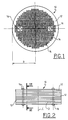
- FIG. 1 shows a flame arrester device 10 of which sees a disc 12, preferably made of metal, provided with a plurality of holes 14.
- Holes 14 are manufactured by drilling or stamping, stamping punching or molding.
- hole diameters 14 are preferably identical and relatively small compared to the diameter of the disc 12. All of said holes 14 must prevent the spread flames or an explosion front but will also allow the fluent substance to pass without disturbing its passage.
- a flame arrester 10 for a vapor recovery system of hydrocarbon and having a radius R of the discs 12 of around 15 mm, preferably some hundreds of holes 14 with a diameter of the order of 0.6 or 0.7 mm.
- the flame arrester 10 consists of several 12 drilled discs which form a package by stack.
- the holes 14 line up and form channels essentially parallel to the line central LC.
- several markers are preferably placed on discs 12.
- the easiest benchmarks to achieve are holes with a reasonable diameter larger than that of the other holes 14 which are also parallel to the central line LC.
- Figure 1 shows for example two marks which finally serve to receive two rivets 16 -as also illustrated in Figure 2- which fix all the discs 12.
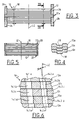
- FIGS. 3 and 4 Another method according to the invention consists in fixing the discs 12 and attach them to each other by pins 18 as shown in FIGS. 3 and 4.
- the Figure 4 shows how the pimples 18 by semi-punctured serve as benchmarks for adjusting the position of a disc 12a compared to each other 12b or from 12b to 12c for example and also to fit together and make the package forming the flame arrester 10.
- FIG. 5 teaches a third mode for fixing several discs 12 in a ring 20, in order to stack them and constitute the flame arrester device according to the invention.
- it is a metallic circle, for example, which surrounds the peripheral of the discs 12 and the end portions 22 of which are placed in such a way that they aim at the central line LC and entwine and fix the discs 12.
- FIG. 5 does not show this because it is obvious, the discs 12 carry marks as already explained above.
- flame arresters in the form of a wafer: with a homogeneous, smooth and flattened outer contour.
- Such flame arresters are typically used inside pipes where they are placed in compliant places.
- a flame arrester device according to the invention where a ring is only used to fix the discs but also has distant end portions 22 which, like sleeves, can themselves receive pipes.
- the flame arrester 10 is provided with at least one of the discs with a diameter greater than that of the others.
- FIG. 3 Another possibility of integrating a device flame arrester 10 according to the invention in a pipe system is shown in Figure 3.
- two 12X discs positioned approximately in the middle of the flame arrester 10 have a larger outer diameter than to the diameters of the other disks 12.
- the sections devices from the 12 drives next to the 12X drives can therefore serve as seats for two pipes 24 and 26.
- the flame arrester 10 still realizes itself a connection between the two pipes 24, 26 without any defect in its functionality main.
- FIG. 6 finally shows another embodiment of the invention.
- Figure 6 shows only five discs 12a, b, c, d, e and two sets of neighboring holes 14.1a-e and 14.2a-e as examples of the assembly which forms the flame arrester 10.
- the disks 12a-e are slightly offset from each other and similarly holes 14.1 a, b, c, d, e and 14.2 a-e.
- the pipe formed by the series of holes 14.1 ae is slightly inclined relative to the central line LC of the flame arrester 10, which is indicated by the angle ⁇ .
- the flame arrester 10 gives the advantage that the speed of a flame front or of an explosion arriving at the flame arrester will no longer be able to propagate over the same line.
- the inclination of the direction of the propagation of the flames weakens the energy of this front in combination with the obstacles created by the said sides formed by the edges of the holes 14.1 and 14.2 which project inside the pipes.
- the increase in the internal surface of each pipe created by such a shift of the discs 12 supports the effect of reducing the energy of the flames (or of the explosion) by heat exchange.
- a disc 12d of a non-metallic material preferably ceramic.
- a plurality of ceramic or generally non-metallic discs can also be used.
- the advantage of a flame arrester according to the invention consists on the one hand in its low cost price, on the other hand in its solidity. No deformation of the flame arrester is not to be feared when a pressure wave from an explosion acts on one side of the device.
Landscapes
- Health & Medical Sciences (AREA)
- Public Health (AREA)
- Business, Economics & Management (AREA)
- Emergency Management (AREA)
- Thermistors And Varistors (AREA)
- Respiratory Apparatuses And Protective Means (AREA)
- Physical Or Chemical Processes And Apparatus (AREA)
- Glass Compositions (AREA)
- Fireproofing Substances (AREA)
- Compositions Of Macromolecular Compounds (AREA)
Description
C'est notamment le cas des pompes où des éléments en mouvement relatif pouvant créer des étincelles par choc. De même une source de chaleur peut être à l'origine d'une déflagration dudit mélange gazeux explosif qu'il importe de limiter dans l'espace et empêcher de se propager.
On souhaite dans tous les cas à réaliser des trous longs et de petit diamètre, ce qui est très difficile à réaliser par des moyens classiques.
- la figure 1 est une vue en-dessus d'un premier mode de réalisation d'un dispositif pare-flammes selon l'invention;
- la figure 2 est une vue de côté du dispositif selon la figure 1;
- la figure 3 est une vue de côté d'un deuxième mode de réalisation de l'invention ;
- la figure 4 est une vue en coupe -en échelle agrandie- d'une particularité du dispositif selon la figure 3 dont la ligne de coupure dans la figure 3 est indiquée par IV-IV ;
- la figure 5 est une vue de côté d'un troisième mode de réalisation de l'invention et
- la figure 6 est une vue en coupe -en échelle agrandie- d'une particularité du dispositif selon la figure 2 dont la ligne de coupure dans la figure 2 est indiquée par VI-VI.
I1 s'agit dans ce cas là d'un cercle métallique, par exemple, qui entoure le périphérique des disques 12 et dont les parties extrèmes 22 sont placées d'une façon qu'elles visent la ligne centrale LC et enlacent et fixent les disques 12. Bien que la figure 5 ne le montre pas car c'est évident, les disques 12 portent des repères comme déjà expliqué ci-dessus.
Dans ce cas là le pare-flammes 10 est muni d'au moins un des disques avec un diamètre supérieur à celui des autres.
Vis-à-vis du but du pare-flammes 10 un tel agencement selon la figure 6 donne l'avantage que la vitesse d'un front de flammes ou d'une explosion arrivant jusqu'au pare-flammes ne pourra plus se propager sur une même ligne. L'inclinaison de la direction de la propagation des flammes affaiblit l'énergie de ce front en combinaison avec les obstacles créés par lesdits côtés formés par les bords des trous 14.1 et 14.2 qui se projettent à l'intérieur des canalisations.
Egalement l'augmentation de la surface interne de chaque canalisation créée par un tel décalage des disques 12 supporte l'effet de diminuer l'énergie des flammes (ou de l'explosion) par échange de la chaleur.
Pour agrandir la chaleur spécifique du pare-flammes 10 selon l'invention, on pourrait intégrer parmi les disques 12c et 12e, comme le montre par exemple la figure 6, un disque 12d d'un matériau non-métallique, préférablement céramique. Sans limiter aucunement l'idée de l'invention, il est évident qu'on peut utiliser aussi une pluralité de disques céramiques ou en général non-métalliques.
Claims (12)
- Dispositif pare-flammes (10) constitué par un ensemble de plusieurs disques (12) formant un paquet par empilement et percés chacun de plusieurs ouvertures (14) essentiellement parallèles par rapport à un flux d'une substance traversant le dispositif, les ouvertures des disques voisins coopérant entre elles pour former des canaux de passage parallèles,
caractérisé en ce que
les disques (12) sont jointifs et les canaux de passage parallèles sont transversalement fermés et ne communiquent pas entre eux. - Dispositif pare-flammes selon la revendication 1,
caractérisé en ce que
chaque disque (12) est muni du même nombre d'ouvertures (14) arrangée selon le même plan. - Dispositif pare-flammes selon la revendication 2,
caractérisé en ce que
les ouvertures (14) sont des trous de même diamètre. - Dispositif pare-flammes selon une des revendications 2 ou 3,
caractérisé en ce que
les ouvertures (14) dans les disques (12) sont fabriquées par forage ou estampage, matriçage, poinçonnage ou moulage. - Dispositif pare-flammes selon une des revendications précédentes,
caractérisé en ce qu'
au moins un des disques (12) est constitué de matériau métallique. - Dispositif pare-flammes selon une des revendications 1 à 4,
caractérisé en ce qu'
au moins un des disques (12) est en matériau céramique. - Dispositif pare-flammes selon une des revendications précédentes,
caractérisé en ce qu'
au moins un des disques (12) a un diamètre supérieur à celui des autres. - Dispositif pare-flammes selon une des revendications 2 à 7,
caractérisé en ce que
chaque ouverture (14) d'un disque (12) est parfaitement alignée avec l'ouverture conforme et voisine du disque voisin. - Dispositif pare-flammes selon une des revendications 2 à 7,
caractérisé en ce que
chaque ouverture (14) d'un disque (12) est légèrement décalée par rapport à celle conforme et voisine du disque voisin. - Dispositif pare-flammes selon une des revendications précédentes,
caractérisé en ce que
les disques (12) formant ledit dispositif (10) sont fixés l'un à l'autre d'une manière démontable. - Dispositif pare-flammes selon une des revendications 1 à 9,
caractérisé en ce que
les disques (12) formant ledit dispositif (10) sont fixés l'un à l'autre par des rivets (16) et/ou des picots (18). - Dispositif pare-flammes selon une des revendications 1 à 9,
caractérisé en ce que
les disques (12) formant ledit dispositif (10) sont fixés par un anneau (20) qui enveloppe l'ensemble des disques à la périphérie.
Applications Claiming Priority (3)
| Application Number | Priority Date | Filing Date | Title |
|---|---|---|---|
| FR9406436A FR2720284B1 (fr) | 1994-05-25 | 1994-05-25 | Dispositif pare-flammes. |
| FR9406436 | 1994-05-25 | ||
| PCT/FR1995/000631 WO1995032024A1 (fr) | 1994-05-25 | 1995-05-16 | Dispositif pare-flammes |
Publications (2)
| Publication Number | Publication Date |
|---|---|
| EP0760701A1 EP0760701A1 (fr) | 1997-03-12 |
| EP0760701B1 true EP0760701B1 (fr) | 2001-08-22 |
Family
ID=9463565
Family Applications (1)
| Application Number | Title | Priority Date | Filing Date |
|---|---|---|---|
| EP95920145A Expired - Lifetime EP0760701B1 (fr) | 1994-05-25 | 1995-05-16 | Dispositif pare-flammes |
Country Status (7)
| Country | Link |
|---|---|
| US (1) | US5816333A (fr) |
| EP (1) | EP0760701B1 (fr) |
| AT (1) | ATE204494T1 (fr) |
| DE (1) | DE69522323T2 (fr) |
| ES (1) | ES2161889T3 (fr) |
| FR (1) | FR2720284B1 (fr) |
| WO (1) | WO1995032024A1 (fr) |
Families Citing this family (8)
| Publication number | Priority date | Publication date | Assignee | Title |
|---|---|---|---|---|
| DE10112957B4 (de) * | 2001-03-17 | 2005-12-22 | Leinemann Gmbh & Co. | Flammensperrenanordnung |
| US20070194053A1 (en) * | 2002-04-26 | 2007-08-23 | Heiner Ophardt | Fire resistant container system |
| DE10308984B4 (de) | 2003-03-01 | 2018-09-27 | Hartwig Straub | Vorrichtung und Verfahren zum Betreiben eines explosionssicheren Schüttgutfilterapparates |
| US7526921B2 (en) * | 2005-03-29 | 2009-05-05 | Honeywell International Inc. | Auxiliary power unit with integral firebox |
| CN103104322B (zh) * | 2013-01-25 | 2016-08-03 | 无锡瑞阳动力科技有限公司 | 用于防爆柴油机的栅栏式阻火器 |
| DE102016006086A1 (de) * | 2016-05-20 | 2017-11-23 | DÜRR Technik GmbH & Co. KG | Vakuumpumpe mit Flammendurchschlagsicherung |
| CN109952471B (zh) * | 2016-10-28 | 2021-05-14 | 金子产业株式会社 | 减速机构以及带减速机构的阻火器 |
| RU2714544C1 (ru) * | 2019-10-17 | 2020-02-18 | Общество с ограниченной ответственностью "Центр Инновационных Технологий-Плюс" | Газообменный фильтр с функцией огнепреградителя и взрывозащиты |
Family Cites Families (8)
| Publication number | Priority date | Publication date | Assignee | Title |
|---|---|---|---|---|
| FR391357A (fr) * | ||||
| DE648463C (de) * | 1936-05-26 | 1937-07-31 | Wilhelm Litz | Begrenzungswand fuer mit Kleinkoerpern gefuellte, als Gasrueckschlagsicherung dienende Gehaeuse |
| US2277294A (en) * | 1939-08-11 | 1942-03-24 | Stephen H Brooks | Self-contained flame arrester bank or unit |
| DE922756C (de) * | 1952-06-19 | 1955-01-24 | Wilke Werke Ag | Sicherung zum Aufhalten von Flammen und Explosionen |
| GB723936A (en) * | 1952-07-01 | 1955-02-16 | West Midlands Gas Board | Improved flame and explosion traps |
| DE1023409B (de) * | 1956-05-24 | 1958-01-23 | Wilke Werke Ag | Sicherheitsvorrichtung fuer Behaelter mit brennbaren Fluessigkeiten |
| US4484690A (en) * | 1982-03-08 | 1984-11-27 | Service Machine Co. | Flame arresting ventilated wall for an explosion-proof enclosure |
| DE69305351T3 (de) * | 1992-06-30 | 2002-11-21 | Combustion Controls, Inc. | Flammen- und explosionsschutzsicherung |
-
1994
- 1994-05-25 FR FR9406436A patent/FR2720284B1/fr not_active Expired - Fee Related
-
1995
- 1995-05-16 DE DE69522323T patent/DE69522323T2/de not_active Expired - Fee Related
- 1995-05-16 EP EP95920145A patent/EP0760701B1/fr not_active Expired - Lifetime
- 1995-05-16 AT AT95920145T patent/ATE204494T1/de not_active IP Right Cessation
- 1995-05-16 US US08/732,508 patent/US5816333A/en not_active Expired - Fee Related
- 1995-05-16 ES ES95920145T patent/ES2161889T3/es not_active Expired - Lifetime
- 1995-05-16 WO PCT/FR1995/000631 patent/WO1995032024A1/fr not_active Ceased
Also Published As
| Publication number | Publication date |
|---|---|
| ATE204494T1 (de) | 2001-09-15 |
| ES2161889T3 (es) | 2001-12-16 |
| FR2720284A1 (fr) | 1995-12-01 |
| US5816333A (en) | 1998-10-06 |
| EP0760701A1 (fr) | 1997-03-12 |
| DE69522323D1 (de) | 2001-09-27 |
| FR2720284B1 (fr) | 1996-06-28 |
| WO1995032024A1 (fr) | 1995-11-30 |
| DE69522323T2 (de) | 2002-05-16 |
Similar Documents
| Publication | Publication Date | Title |
|---|---|---|
| EP2682655B1 (fr) | Electrovanne du type à noyau plat et ressort plat | |
| CA3011196A1 (fr) | Echangeur de chaleur a condensation muni d'un dispositif d'echanges thermiques | |
| EP0611235A1 (fr) | Echangeur de chaleur pour composants électroniques et appareillages électrotechniques | |
| EP0760701A1 (fr) | Dispositif pare-flammes | |
| EP2715816A1 (fr) | Module et dispositif thermo electriques, notamment destines a generer un courant electrique dans un vehicule automobile | |
| FR2880417A1 (fr) | Refroidisseur d'huile a filtre integre | |
| EP1818617A1 (fr) | Paroi transversale de chambre de combustion munie de trous de multiperforations | |
| FR2978236A1 (fr) | Echangeur thermique, tube plat et plaque correspondants | |
| FR2997485A1 (fr) | Echangeur thermique, notamment pour vehicule automobile | |
| EP1533585B1 (fr) | Echangeur de chaleur à empilement de plaques | |
| WO2022069817A1 (fr) | Reacteur tubulaire a lit fixe | |
| FR2856784A1 (fr) | Echangeur de chaleur | |
| EP3234488B1 (fr) | Plaque d'echange thermique a microcanaux et echangeur thermique comportant au moins une telle plaque | |
| EP4196253B1 (fr) | Reacteur tubulaire a lit fixe | |
| FR2737255A1 (fr) | Joint de culasse pour moteur a combustion interne | |
| FR2850153A1 (fr) | Joint d'etancheite a structure interne lamellaire pour tres hautes temperatures. | |
| EP3861270B1 (fr) | Paire de plaques pour un échangeur de chaleur à plaques | |
| EP3099994A1 (fr) | Echangeur de chaleur pour véhicule automobile | |
| EP0679239B1 (fr) | Procede de fabrication d'un element de bruleur a gaz, element de bruleur et bruleur en faisant utilisation | |
| EP0173618A1 (fr) | Inducteur à culasse magnétique pour équipement de fabrication de fibres de verre | |
| EP2009383A1 (fr) | Boîte collectrice pour échangeur de chaleur | |
| WO2014195650A1 (fr) | Chargement pyrotechnique et generateur de gaz comprenant un tel chargement | |
| FR2657954A1 (fr) | Dispositif d'echange thermique a plaques planes et a turbulateurs. | |
| EP0410825B1 (fr) | Echangeur à plaques à circuits étanches | |
| EP0679838B1 (fr) | Perfectionnements aux brûleurs à gaz |
Legal Events
| Date | Code | Title | Description |
|---|---|---|---|
| PUAI | Public reference made under article 153(3) epc to a published international application that has entered the european phase |
Free format text: ORIGINAL CODE: 0009012 |
|
| 17P | Request for examination filed |
Effective date: 19961106 |
|
| AK | Designated contracting states |
Kind code of ref document: A1 Designated state(s): AT BE CH DE DK ES FR GB IT LI NL SE |
|
| RAP1 | Party data changed (applicant data changed or rights of an application transferred) |
Owner name: SOLUTIONS SERVICES SYSTEMES FRANCE |
|
| 17Q | First examination report despatched |
Effective date: 19990514 |
|
| GRAG | Despatch of communication of intention to grant |
Free format text: ORIGINAL CODE: EPIDOS AGRA |
|
| GRAG | Despatch of communication of intention to grant |
Free format text: ORIGINAL CODE: EPIDOS AGRA |
|
| GRAH | Despatch of communication of intention to grant a patent |
Free format text: ORIGINAL CODE: EPIDOS IGRA |
|
| GRAH | Despatch of communication of intention to grant a patent |
Free format text: ORIGINAL CODE: EPIDOS IGRA |
|
| GRAA | (expected) grant |
Free format text: ORIGINAL CODE: 0009210 |
|
| AK | Designated contracting states |
Kind code of ref document: B1 Designated state(s): AT BE CH DE DK ES FR GB IT LI NL SE |
|
| PG25 | Lapsed in a contracting state [announced via postgrant information from national office to epo] |
Ref country code: AT Free format text: LAPSE BECAUSE OF FAILURE TO SUBMIT A TRANSLATION OF THE DESCRIPTION OR TO PAY THE FEE WITHIN THE PRESCRIBED TIME-LIMIT Effective date: 20010822 |
|
| REF | Corresponds to: |
Ref document number: 204494 Country of ref document: AT Date of ref document: 20010915 Kind code of ref document: T |
|
| REG | Reference to a national code |
Ref country code: CH Ref legal event code: EP |
|
| REF | Corresponds to: |
Ref document number: 69522323 Country of ref document: DE Date of ref document: 20010927 |
|
| RAP2 | Party data changed (patent owner data changed or rights of a patent transferred) |
Owner name: TOKHEIM SERVICES FRANCE |
|
| PG25 | Lapsed in a contracting state [announced via postgrant information from national office to epo] |
Ref country code: SE Free format text: LAPSE BECAUSE OF FAILURE TO SUBMIT A TRANSLATION OF THE DESCRIPTION OR TO PAY THE FEE WITHIN THE PRESCRIBED TIME-LIMIT Effective date: 20011122 Ref country code: DK Free format text: LAPSE BECAUSE OF FAILURE TO SUBMIT A TRANSLATION OF THE DESCRIPTION OR TO PAY THE FEE WITHIN THE PRESCRIBED TIME-LIMIT Effective date: 20011122 |
|
| GBT | Gb: translation of ep patent filed (gb section 77(6)(a)/1977) |
Effective date: 20011117 |
|
| REG | Reference to a national code |
Ref country code: ES Ref legal event code: FG2A Ref document number: 2161889 Country of ref document: ES Kind code of ref document: T3 |
|
| BECN | Be: change of holder's name |
Effective date: 20010822 |
|
| REG | Reference to a national code |
Ref country code: GB Ref legal event code: IF02 |
|
| NLT2 | Nl: modifications (of names), taken from the european patent patent bulletin |
Owner name: TOKHEIM SERVICES FRANCE |
|
| PG25 | Lapsed in a contracting state [announced via postgrant information from national office to epo] |
Ref country code: LI Free format text: LAPSE BECAUSE OF NON-PAYMENT OF DUE FEES Effective date: 20020531 Ref country code: CH Free format text: LAPSE BECAUSE OF NON-PAYMENT OF DUE FEES Effective date: 20020531 |
|
| PLBE | No opposition filed within time limit |
Free format text: ORIGINAL CODE: 0009261 |
|
| STAA | Information on the status of an ep patent application or granted ep patent |
Free format text: STATUS: NO OPPOSITION FILED WITHIN TIME LIMIT |
|
| 26N | No opposition filed | ||
| REG | Reference to a national code |
Ref country code: CH Ref legal event code: PL |
|
| PG25 | Lapsed in a contracting state [announced via postgrant information from national office to epo] |
Ref country code: FR Free format text: LAPSE BECAUSE OF NON-PAYMENT OF DUE FEES Effective date: 20030131 |
|
| REG | Reference to a national code |
Ref country code: FR Ref legal event code: ST |
|
| PGFP | Annual fee paid to national office [announced via postgrant information from national office to epo] |
Ref country code: BE Payment date: 20050427 Year of fee payment: 11 |
|
| PGFP | Annual fee paid to national office [announced via postgrant information from national office to epo] |
Ref country code: GB Payment date: 20050429 Year of fee payment: 11 |
|
| PGFP | Annual fee paid to national office [announced via postgrant information from national office to epo] |
Ref country code: ES Payment date: 20050504 Year of fee payment: 11 |
|
| PGFP | Annual fee paid to national office [announced via postgrant information from national office to epo] |
Ref country code: DE Payment date: 20050521 Year of fee payment: 11 |
|
| PGFP | Annual fee paid to national office [announced via postgrant information from national office to epo] |
Ref country code: NL Payment date: 20050531 Year of fee payment: 11 |
|
| PG25 | Lapsed in a contracting state [announced via postgrant information from national office to epo] |
Ref country code: GB Free format text: LAPSE BECAUSE OF NON-PAYMENT OF DUE FEES Effective date: 20060516 |
|
| PG25 | Lapsed in a contracting state [announced via postgrant information from national office to epo] |
Ref country code: ES Free format text: LAPSE BECAUSE OF NON-PAYMENT OF DUE FEES Effective date: 20060517 |
|
| PG25 | Lapsed in a contracting state [announced via postgrant information from national office to epo] |
Ref country code: BE Free format text: LAPSE BECAUSE OF NON-PAYMENT OF DUE FEES Effective date: 20060531 |
|
| PGFP | Annual fee paid to national office [announced via postgrant information from national office to epo] |
Ref country code: IT Payment date: 20060531 Year of fee payment: 12 |
|
| PG25 | Lapsed in a contracting state [announced via postgrant information from national office to epo] |
Ref country code: NL Free format text: LAPSE BECAUSE OF NON-PAYMENT OF DUE FEES Effective date: 20061201 Ref country code: DE Free format text: LAPSE BECAUSE OF NON-PAYMENT OF DUE FEES Effective date: 20061201 |
|
| GBPC | Gb: european patent ceased through non-payment of renewal fee |
Effective date: 20060516 |
|
| NLV4 | Nl: lapsed or anulled due to non-payment of the annual fee |
Effective date: 20061201 |
|
| REG | Reference to a national code |
Ref country code: ES Ref legal event code: FD2A Effective date: 20060517 |
|
| BERE | Be: lapsed |
Owner name: *TOKHEIM SERVICES FRANCE Effective date: 20060531 |
|
| PG25 | Lapsed in a contracting state [announced via postgrant information from national office to epo] |
Ref country code: IT Free format text: LAPSE BECAUSE OF NON-PAYMENT OF DUE FEES Effective date: 20070516 |