EP0760475A2 - Verfahren und Vorrichtung zur Ellipsometrie mit Vielfachdetektoren - Google Patents
Verfahren und Vorrichtung zur Ellipsometrie mit Vielfachdetektoren Download PDFInfo
- Publication number
- EP0760475A2 EP0760475A2 EP96401670A EP96401670A EP0760475A2 EP 0760475 A2 EP0760475 A2 EP 0760475A2 EP 96401670 A EP96401670 A EP 96401670A EP 96401670 A EP96401670 A EP 96401670A EP 0760475 A2 EP0760475 A2 EP 0760475A2
- Authority
- EP
- European Patent Office
- Prior art keywords
- processing unit
- light beam
- digital signal
- multiplexing
- input channels
- Prior art date
- Legal status (The legal status is an assumption and is not a legal conclusion. Google has not performed a legal analysis and makes no representation as to the accuracy of the status listed.)
- Granted
Links
Images

Classifications
-
- G—PHYSICS
- G01—MEASURING; TESTING
- G01N—INVESTIGATING OR ANALYSING MATERIALS BY DETERMINING THEIR CHEMICAL OR PHYSICAL PROPERTIES
- G01N21/00—Investigating or analysing materials by the use of optical means, i.e. using sub-millimetre waves, infrared, visible or ultraviolet light
- G01N21/17—Systems in which incident light is modified in accordance with the properties of the material investigated
- G01N21/21—Polarisation-affecting properties
- G01N21/211—Ellipsometry
Definitions
- the present invention relates to a multi-detector ellipsometer and to a multi-detector ellipsometric measurement method.
- Ellipsometry is a non-destructive measurement technique allowing the optical characterization of a sample with a specular or quasi-specular surface.
- This measurement is generally carried out at oblique incidence, but can also be made at normal incidence, the ellipsometry then being called Anisotropic Spectroscopic Reflection (RAS, Reflexion Anisotropy Spectroscopy) or Differential Spectroscopic Reflectance (RDS, Reflectance Difference Spectroscopy).
- RAS Anisotropic Spectroscopic Reflection
- RDS Differential Spectroscopic Reflectance
- Ellipsometry can also be extended to rough surfaces or to the scattering of light by particles of a physical system.
- Ellipsometry can be implemented in situ and then allows the study of the mechanisms of growth of thin layers, formation of interfaces and the control of processes for the development of these layers and interfaces. Ellipsometry is, for example, used for the study and control of the manufacture of semiconductors.
- Ellipsometric measurements can be performed at a fixed wavelength, or at several wavelengths (spectroscopic ellipsometry). Depending on the wavelength range of the source: near ultraviolet, visible, near infrared, infrared, etc., it is possible to access different properties of the layers, materials or to explore different materials.
- the penetration depth of the radiation is often small. This constitutes favorable conditions for the study of surfaces and interfaces, and for controls in real time. This generally does not allow access to volume properties layers and materials which can, on the contrary, be obtained by measurements in the infrared field. Infrared is well suited to vibrational absorption measurements (chemical bonds).
- the surface of a sample is illuminated by a light beam and the polarization state of an incident beam is compared to that of the reflected or transmitted beam.
- the beam reflected or transmitted by the sample will be referred to as the returned beam.
- the ellipsometric measurements can be carried out in the presence of an alternative external excitation, for example of the optical, electrical or magnetic type, the corresponding technique being respectively called photo-ellipsometry, electro-ellipsometry and magneto-ellipsometry.
- the polarization state of the returned beam depends on the properties of the sample, the angle of incidence of the incident beam, and the measurement wavelength. The relationship between this state of polarization and these parameters is given by the Fresnel equations cited, for example, by D. CHARLOT and A. MARUANI in Appl. Opt. 24, 3368, 1985.
- phase modulation ellipsometer In a phase modulation ellipsometer, an incident ray has its polarization modulated by a phase difference generated between two eigen axes of a phase modulator.
- the phase shift typically evolves with time t according to a periodic law of modulation frequency Fm, this phase shift being proportional to the first order at sin (2 Fm t).
- Fm periodic law of modulation frequency
- Ellipsometry and more particularly spectroscopic phase modulation ellipsometry (ESMP) is a powerful technique for measuring in real time the growth of layers on a substrate. This technique has the advantage of not disturbing reactions in progress. She is also very sensitive to physical parameters of the measured sample, such as a layer thickness and a refractive index. On the other hand, it allows quick measurements.
- ESMP spectroscopic phase modulation ellipsometry
- a spectroscopic phase modulation ellipsometer comprises a single photodetector, measuring a light flux reflected by a sample.
- the recording of a spectrum then requires the scanning of a dispersive system, such as a prism or a network, for times which can reach several tens of seconds.
- This ellipsometer is therefore not very suitable for real-time measurements of rapidly evolving phenomena.
- an ellipsometer comprising, in addition to an electronic processing unit, a spectrograph and several photodetectors.
- An illustration of this can be found with 4 photodetectors by B. DREVILLON in "Progress in Crystal Growth and Characterization of Materials", vol. 27, num. 1, pp. 1-87, 1993 (pages 14 and 15).
- the photodetectors are adjusted to the spectrograph, so as to measure the fluxes of a light beam reflected by a sample and broken down by the spectrograph.
- the photodetectors connected to the electronic processing unit by connections or input channels produce in the input channels measured signals, from which the electronic processing unit calculates physical parameters of the sample.
- the electronic processing unit is synchronized with the phase modulator and performs operations successively associated with the different input channels, according to acquisition phases possibly of the same duration.
- the duration of the acquisition phases is a multiple of the modulation period Tm, equal to the inverse of the modulation frequency Fm.
- the electronic processing unit receives a measured signal from one of the input channels. Then it switches to another input channel to go to the acquisition phase next.
- the ellipsometer thus uses a so-called sequential mode acquisition technique.
- This multi-detector ellipsometer makes it possible to use several wavelengths of the reflected light beam more efficiently and more quickly than a conventional ellipsometer comprising a single photodetector. However, its possibilities remain significantly below the needs created by real-time measurements.
- the sequential mode can hardly be extended to a large number of photodetectors, such as several tens for example, because of the time required to scan all of the input channels.
- the present invention relates to a spectroscopic multi-detector ellipsometer with phase modulation, making it possible to significantly accelerate measurements in real time compared to existing devices.
- the invention relates to a spectroscopic ellipsometer allowing the quasi-simultaneous acquisition of a large number of wavelengths, this acquisition considerably reducing the duration of a cycle.
- the invention also has for objective a multi-detector ellipsometer allowing quasi-simultaneous acquisitions at several points of a sample.
- the invention aims at a multi-detector ellipsometer allowing the reading in parallel of a large number of photo-detectors.
- Another object of the invention is to provide a rapid multi-detector ellipsometric measurement method, applicable to quasi-simultaneous measurements of several pieces of information in real time.
- the sequencer comprises means making it possible to impose on the switching frequency Fe to be a multiple of the modulation frequency Fm.
- the switching frequency Fe is a divider of the modulation frequency Fm.
- the switching frequency Fe is a multiple of the modulation frequency Fm.
- the information coming from the various photodetectors is not acquired sequentially but in a crossed fashion.
- the reading of the photodetectors by the electronic processing unit therefore involves operations in parallel.
- the ellipsometer according to the invention is particularly suitable for real-time measurements of physical phenomena.
- the sample studied consists of a non-transparent material.
- the incident light beam is then reflected by the sample.
- samples made of transparent materials by transmission of the incident light beam through the sample, while remaining within the scope of ellipsometry.
- the multiplexing and digitization assembly producing values of the digital signal multiplexed at sampling points, the switching frequency is equal to the modulation frequency multiplied by the number of input channels and by the number of points sampling by input channel and by modulation period.
- the configuration of the multi-detector ellipsometer thus obtained gives the ellipsometer optimum efficiency and speed. Indeed, at each Tm modulation period, the electronic processing unit scans all of the input channels. It thus acquires in parallel, almost simultaneously, information from all the photodetectors.
- the multiplexing and digitizing assembly comprises a multiplexer connected to the input channels and a digitizer connected to the multiplexer, the multiplexer multiplexing into an analog signal multiplexed the analog signals measured by successively switching to the input channels, and the digitizer converting the multiplexed analog signal into a multiplexed digital signal.
- This solution has the advantage of requiring a single digitizer, which makes this embodiment inexpensive and easy to carry out.
- the separation of the multiplexer and the digitizer can be only purely theoretical, the two corresponding functions being able to be carried out in only one material element.
- the electronic processing unit advantageously comprises a preliminary calculation unit connected to the digitizer and to the digital signal processing unit, this preliminary calculation unit carrying out prior filtering of the multiplexed digital signal, by integration over several modulation periods.
- the acquisition and processing of the data acquired during these Tm modulation periods constitute a cycle of the ellipsometer according to the invention.
- the ellipsometer according to the invention comprises means for additional external excitation of the sample capable of generating an additional modulation at an excitation frequency distinct from the polarization modulation frequency.
- the ellipsometer comprises a clock external to the electronic processing unit generating the modulation frequency and a frequency multiplication system.
- the external clock is connected to the sequencer through the frequency multiplication system, and the sequencer produces the switching frequency from the modulation frequency.
- the electronic processing unit comprises an internal clock generating the modulation and switching frequencies.
- This internal clock is typically used with an electro-optical modulator.
- the electronic processing unit comprises at least one printed circuit card, this card preferably comprising at least one programmable logic circuit.
- the ellipsometer it is also advantageous for the ellipsometer according to the invention to include a preprocessing memory disposed between the multiplexing and digitization assembly and the digital signal processing unit.
- This preprocessing memory stores the multiplexed digital signal for at least one modulation period and then restores it to the digital signal processing unit.
- the ellipsometer according to the invention advantageously comprises a user interface allowing the connection of the electronic processing unit to a communication network.
- the switching frequency is a multiple of the modulation frequency, so that at the output of the multiplexing and digitization assembly, the components are interleaved in the multiplexed digital signal.
- the parts of the returned light beam reaching the photodetectors are produced by a spectral decomposition in wavelength.
- the parts of the returned light beam reaching the photodetectors are produced by spatial decomposition and come from different areas of the sample.
- the parts of the returned light beam reaching the photodetectors are produced by a decomposition into different polarization states.
- the ellipsometric measurement can be carried out in the presence of an additional modulated external excitation.
- Figure 1 is a schematic representation of a multi-detector ellipsometer according to the invention.
- Figure 2 is a schematic representation of the electronic processing unit of the ellipsometer shown in Figure 1.
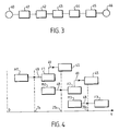
- FIG. 3 is a block diagram of the operations performed by the electronic processing unit of Figure 2.
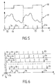
- Figure 4 shows the sequence in time of the acquisition and processing operations carried out by the electronic processing unit of Figure 2 during several cycles.
- Figure 5 represents the temporal evolutions of the modulation signal generated by the phase modulator of the ellipsometer of Figure 1, of the signal measured in one of the input channels, and of the sampling carried out by the electronic processing unit of Figure 2 on this entry path.
- Figure 6 shows the interleaving of the samples performed by the electronic processing unit of Figure 2 for the different input channels respectively.
- the multi-detector ellipsometer represented in FIG. 1, is intended for the measurement of physical parameters of a sample 1. It comprises an excitation group 2, an analysis group 3, an electronic processing unit 4, and a user interface 5.
- the excitation group 2 comprises a light source 20 connected to an optical system 22 via an optical fiber 21, the optical system 22 directing a light beam emitted by the source 20 towards the sample 1.
- the group d excitation 2 also includes a polarizer 23 followed by a phase modulator 24 between the optical system 22 and the sample 1.
- This phase modulator 24 typically consists of a molten silica bar subjected to a periodic stress generated by a piezo transducer -electric. This creates a phase shift modulated with time between two own axes of this bar, thus modulating the polarization of emerging light rays.
- the analysis group 3 comprises an analyzer 30 analyzing a beam reflected by the sample 1, followed by an optical system 31 addressing the beam reflected on a spectrograph 36 via an optical fiber 32.
- the spectrograph 36 is arranged so as to scatter light on a series of photodetectors 37, numbering n, each of them allowing the measurement of a wavelength.
- Each of the photodetectors 37 transforms the intensity of a flux detected in an electrical signal.
- the multi-detector spectroscopic ellipsometer of FIG. 1 thus makes it possible to simultaneously measure several wavelengths, a multiplexing being able to be carried out in the electronic processing unit 4.
- the latter also receives a frequency and phase reference from the modulator of phase 24 by line 35.
- the electronic processing unit 4 communicates with the user interface 5, which is typically a computer console.
- the electronic processing unit 4 can be connected to a computer network, such as that marketed under the name "Ethernet”. Its connection to an international network makes it possible to carry out maintenance even at a very great distance from the ellipsometer.
- the light source 20 emits an incident light beam 10 in a given wavelength range, this beam being linearly polarized by the polarizer 23, then undergoing modulation by the phase modulator 24.
- the incident light beam 10 polarized being defined by a polarization vector
- the phase modulator 24 introduces between perpendicular components of the polarization vector, a time-dependent phase shift according to a periodic variation in frequency Fm.
- the incident and polarized and modulated light beam 10 becomes, after reflection on the sample 1, a reflected beam 11 having an amplitude and a phase resulting from the physical properties of the sample 1.
- This reflected beam 11 is analyzed in the analyzer 30, then spectrally decomposed in the spectrograph 36.
- the photodetectors 37 then measure the fluxes of the reflected light beam 11 at different wavelengths. They respectively produce in entry routes 6, electrical signals generated by the intensity of the flows, or analog signals measured 40. These signals 40 are received by the electronic processing unit 4.
- the electronic processing unit 4 then calculates from these measured analog signals 40, physical parameters 46 of the sample 1, such as a layer thickness or a refractive index.
- the phase modulation spectroscopic ellipsometer shown in FIG. 1, is advantageously used in a device for controlling the production of layers on a substrate.
- Sample 1 then consists of a substrate on which a deposit is grown by a known technique.
- the previously described ellipsometer is used to monitor layer growth on the substrate. By this means, in situ measurements are carried out in real time which do not disturb the growth process. Instead of a layer growth, the elaboration can consist of an etching.
- the user interface 5 makes it possible to supervise operations carried out by the electronic processing unit 4, by triggering them and / or by controlling them, and to exchange information with it. It thus makes it possible to decide on initializations and calculations, to define and transmit acquisition parameters, and to retrieve results for visualizations. It also makes remote maintenance of the electronic processing unit 4 possible.
- the acquisition parameters include, for example, measurement durations, numbers of acquisition points and trigger types.
- the electronic processing unit 4 comprises a multiplexing and digitizing assembly 7 to which the input channels 6 lead, multiplexing and converting the measured analog signals 40 into a multiplexed digital signal.
- This assembly 7 is composed of a multiplexer 12 and a digitizer 13, the output of the multiplexer 12 being connected to the input of the digitizer 13.
- the multiplexer 12 is an analog multiplexer capable of multiplexing the measured analog signals 40 into a multiplexed analog signal, by switching successively to the input channels 6.
- the time required for the multiplexer 12 to switch from an input channel 6 to a other and establishing the multiplexed analog signal at the input of the digitizer 13 is of the order of 10 to 15 nanoseconds for current commercial circuits.
- the digitizer 13, or analog-digital converter is typically a 12-bit digitizer currently marketed, making it possible to convert on the order of 20 to 30 million samples per second.
- the multiplexing and digitization assembly 7 is designed to carry out from each input channel 6 a sampling of P points per modulation period Tm. Each of the analog signals measured 40 is therefore sampled according to an equal sampling period Tp at Tm / P.
- the electronic processing unit 4 also includes a first calculation unit 14 connected to the multiplexing and digitization assembly 7. Its function is to perform a prior filtering of the multiplexed digital signal, by integration over several modulation periods Tm associated with a cycle.
- the number N of these modulation periods Tm of a cycle is chosen by a user as a function of the phenomena observed with the ellipsometer.
- Each cycle corresponds to an acquisition time Ta equal to N x Tm, the physical parameters 46 of sample 1 being determined for this cycle immediately after acquisition.
- the number N must be small enough to be able to follow evolutionary phenomena measured in real time on the sample 1.
- the larger N the better the precision obtained for a given state of the sample 1.
- the number N is between 50 and 1,000,000 for a modulation frequency Fm of 50 kHz.
- the acquisition time Ta is then between I ms and 20 s.
- the prior filtering of the multiplexed digital signal carried out by the first calculation unit 14 implements an averaging technique requiring addition-accumulation, and producing results stored in acquisition points.
- each acquisition point has a storage capacity of 32 bits.
- the number of acquisition points for each input channel 6 is equal to the number P of sampling points per modulation period Tm.
- the results calculated by the first calculation unit 14 are stored in a first dual-access memory 15.
- This first memory 15 acts as a buffer memory between the first calculation unit 14 and the next stage.
- the processing unit 16 can for example be that sold under the brand TMS 320C31 by the company TEXAS INSTRUMENT, capable of performing 32-bit floating point operations.
- the processing unit 16 has the function of carrying out Fourier analyzes on the results obtained by the first calculation unit 14 and stored in the first memory 15. It acquires data globally for each cycle, and therefore receives at the end of each accumulation a set of values typically coded on 32 bits.
- Fourier analyzes are preferably performed by operations of the Fast Fourier Transforms or FFT (Fast Fourier Transform) type. They lead to Fourier parameters, which are stored in a second dual access memory 17.
- This second memory 17 has its input connected to the processing unit 16.
- the output of the second memory 17 is connected to a second calculation unit 18. This is intended to calculate the physical parameters 46 from the Fourier parameters determined by the digital signal processing unit 16.
- the electronic processing unit 4 also includes a sequencer 19 connected to the elements 12, 13, 14 and 16 previously described, having the function of sending them synchronization signals. It thus makes it possible to control processes and to synchronize them.
- the sequencer 19 is connected to the phase modulator 24 by the reference line 35, and is synchronized with respect to the phase modulator 24 by means of a frequency multiplication system. This system typically consists of a phase-locked loop (PLL).
- PLL phase-locked loop
- each element of the electronic processing unit 4 with the exception of the sequencer 19 only dialogs with elements which are directly adjacent to it.
- the functions of the sequencer 19 do not only concern the coordination of acquisitions with the phase modulator 24. They also apply to the start of acquisitions, as a function of a triggering coming for example from an external validation signal, and to the start of the different calibration phases.
- the first calculation unit 14 and at least part of the sequencer 19 are grouped in at least one programmable logic circuit or FPGA (Field Programmable Gate Array), the functional characteristics of this type of integrated circuit being able to be configured by a user.
- FPGA Field Programmable Gate Array
- This programmable logic circuit is able to perform commands in parallel, working in overlapping mode (pipelining) as opposed to sequential execution of operations.
- the digital signal processing unit 16 uses a floating point processor.
- the second computing unit 18 is part of a central unit, of the personal computer or PC type, managed by a multi-tasking operating system in real time. This central unit is able to operate in different modes: acquisition, control, calculation, access to an external network, and statistics.
- the central unit comprises a bus to which the printed circuit board containing the elements 12 to 17 and 19 can be connected, this bus possibly being for example of one of the types marketed under the names ISA and PCI.
- the printed circuit board is programmable from the central unit or via a network of the type called "Ethernet" by downloading. It is thus possible to define the configuration of the card according to the desired operating mode, to load test configurations, to update versions according to the evolution of the ellipsometer, and to carry out remote maintenance on site without manipulation of the card.
- the central unit comprising the second calculation unit 18 is capable of receiving several printed circuit cards such as that described above, all of the cards being connected to the bus of the central unit. More information can be processed and correlated.
- the ellipsometer may include printed circuit boards fulfilling specific functions necessary for operation of the ellipsometer, such as positioning, shutter, and power controls.
- the electronic processing unit 4 can advantageously include such components.
- the electronic processing unit 4 can operate autonomously without requiring a link with the user interface 5. It then performs a series of pre-recorded operations, or defined by prior loading from a source system. At the end of the operation, it is then able to transmit the results obtained to a network, towards one or more end users.
- the electronic processing unit 4 can therefore be considered as a complete system, called "embedded" (Embedded System).
- the electronic processing unit 4 can also be connected to another system, for example in order to control a production process. In particular, this joint use can be used for depositing thin layers.
- the user interface 5 is itself capable of communicating not only with the electronic processing unit 4, but also with other applications, which can make it possible, for example, to correlate the information coming from several devices.
- the following steps shown in FIG. 3 are carried out successively by the electronic processing unit 4.
- a first multiplexing step 41 the measured analog signals 40 arriving at the multiplexer 12 by the input channels 6 are multiplexed into a multiplexed analog signal.
- the multiplexed analog signal is converted by the digitizer 13 into a multiplexed digital signal.
- the multiplexed digital signal is integrated by the first calculation unit 14.
- the results of the prior filtering accumulated for an acquisition cycle in the first memory 15 are processed by the unit digital signal processing 16 during a fourth step 44 of Fourier analysis.
- the processing unit 16 extracts components corresponding respectively to the input channels 6 and calculates, for each of the components, associated Fourier parameters.
- the Fourier parameters calculated for each of the analog signals measured 40 consist of the continuous components, at the frequency Fm and at the frequency 2Fm of these signals.
- the physical parameters 46 are then determined by the second calculation unit 18 from the Fourier parameters stored in the second memory 17, during a fifth step 45 of calculation of the physical parameters 46. A description of these calculations is found in l article by B. DREVILLON previously cited.
- Mi is called the set of multiplexing steps 41, digitization 42 and prior filtering 43 for cycle number i and Fi the step 44 of Fourier analysis for this same cycle.
- the first acquisition cycle is started. All of the analog signals measured 40 coming from the n input channels 6 are then successively multiplexed, digitized and previously filtered, during phase M1. The results obtained are stored progressively by acquisition points in the first memory 15.
- the phase M1 has a duration approximately equal to the duration of acquisition Ta, being equal to N x Tm, since all the operations during this phase M1 are carried out as and when acquisitions.
- phase M2 thus takes place between the instants Ta and 2Ta, the phase F1 of the first cycle being conducted during this time.
- the number of data processed during phase F1 is generally small compared to the previous phase M1, due to the consolidation carried out by integration during step 43 of prior filtering, so that the available processing time leaves the possibility to perform complex calculations.
- a transfer of information 49 from the second memory 17 to the second calculation unit 18 finally makes it possible to calculate the physical parameters 46 sought during step 45.
- this step 45 is carried out independently of the phases M1 and F1 above, because it is performed by the central unit.
- the transfer 49 of the Fourier parameters can therefore be carried out before the end of the second acquisition period Ta, and even before the end of the phase F1, as the Fourier parameters associated with the different input channels 6 are available .
- phase F2 begins at the same time as the acquisitions starting the phase M3 of the third cycle. All the operations described above are then reproduced identically with an incrementation of the number i of the cycle.
- the phase modulator 24 produces, as a function of time t, a reference signal 50 having the modulation period Tm, for example in a slot, as shown in FIG. 5.
- the photodetectors 37 measuring fluxes of the light beam 11 at different wavelengths generate in analog input channels 6 measured signals 40 admitting themselves the modulation period Tm.
- Tm modulation period
- the multiplexing and digitization assembly 7 performs on this measured analog signal 51 a sampling of P sampling points 53 over each modulation period Tm. In the example shown in FIG. 5, the number P is 4.
- the signal analog measured 51 is therefore sampled at a period Tp equal to Tm / P.
- sampling period Tp is divided into n equal parts (n being the number of input channels 6), which define a period of switching Te being Tp / n.
- the multiplexer 12 acquires one of the measured analog signals 40 coming from one of the input channels 6. At the end of this period, it selects by switching the next input channel 6. In a sampling period Tp, the multiplexer 12 thus scans all of the input channels 6. Each time the multiplexer 12 is connected to an input channel 6, the digitizer 13 extracts a sampling point.
- the sequencing of the samples according to the different input channels 6 is therefore carried out as follows, as shown in FIG. 6.
- the multiplexing and digitization assembly 7 selects a sampling point 53 on the analog signal measured 51 coming from the first of the input channels 6.
- the assembly 7 switches to the second of the input channels 6 and selects a sampling point 54 on the analog signal measured that comes from it.
- This operation is repeated for the third, then up to the n-th input channels 6, for which are selected respectively from the sampling points 55 and 56.
- the multiplexer 12 then again selects the first of the input channels 6, so that the assembly 7 of multiplexing and digitization again produces a value of the measured analog signal 51 at another sampling point 53, after a sampling period Tp since the start of the acquisitions.
- the set 7 proceeds in the same way as indicated above for the following (P-1) sampling periods Tp, until the complete progress of a modulation period Tm, then of the N modulation periods Tm constituting the first cycle.
- the acquisition time Ta corresponding to a cycle is independent of the number n of input channels 6, thanks to the parallelism of the operations. It is equal to N x Tm.
- the multiple time offsets of the switching period Te obtained between the samplings of the different analog signals measured 40 are taken into account by the digital signal processing unit 16 by means of corrective terms dependent on the number of the input channel 6 considered. . These corrective terms are used in particular to determine the phase of the Fourier components at the frequencies Fm and 2Fm, with respect to the reference signal 50.
- the successive acquisitions of the multiplexing and digitization assembly 7 are controlled by the sequencer 19, which sends the synchronization signals to the switching period Te.
- the sequencer 19 produces these signals from the reference signal 50 of the phase modulator 24, by frequency multiplication.
- the modulation frequency Fm is equal to 50 kHz
- the number n of channels input 6 is 32 and the number P of points is 8.
- the digitizer 13 must therefore extract Fm xnx P values per second, or 12.8 million values per second. This speed is consistent with the capabilities of the digitizer 13, which can convert on the order of 20 to 30 million samples per second, taking into account the switching time of the multiplexer 12 and the signal establishment time at the input of the digitizer 13.
- the switching period Te is then approximately 78 ns.
- the first calculation unit 14 thus receives information at a high rate, corresponding to a data item of 12 bits every 78 ns.
- the digital signal processing unit 16 receives information only after durations equal to the acquisition duration Ta, usually greater than or equal to 1 ms. This information results from the integration over a cycle of the values received by the first calculation unit 14, in order to obtain averages over a modulation period Tm.
- the digital signal processing unit 16 therefore receives for each cycle P xn, i.e. 256, values coded on 32 bits.
- the modulation frequency Fm, the number n of input channels 6, the number P of sampling points per modulation period Tm, as well as the durations Tp and Te which result therefrom, can be very different.
- another valid embodiment with the same digitizer 13 consists in using a modulation frequency Fm equal to 100 kHz, 16 input channels 6, and 8 sampling points per input channel 6 and per modulation period Tm.
- the modulation frequency Fm is low compared to the capacities of the electronic processing unit 4, it is possible to modify the acquisition conditions to improve the processing of the data by accumulating sampling points, which has the effect of '' improve the apparent resolution of the digitizer 13.
- the switching frequency Fe is then always a multiple of the modulation frequency Fm multiplied by the number n of input channels 6, but more necessarily by the number P of sampling points.
- the switching frequency Fe is then a multiple of the modulation frequency Fm multiplied by the number P, but more necessarily by the number n of input channels 6.
- the solution adopted in the example of illustration is however optimal if the capacities of the multiplexer 12 allow it, insofar as the acquisitions of the n input channels 6 are quasi-simultaneous.
- the ellipsometer according to the invention can be supplemented by external excitation means capable, for example, of sending to the sample 1 an additional optical beam of excitation independent at a frequency distinct from the modulation frequency Fm.
- This excitation can also be of an electrical or magnetic nature.
- the multiplexing and digitization assembly 7 can be produced in a different way than that presented. It is thus possible to use a digitizer per input channel 6, the digital signals obtained then being multiplexed by a digital multiplexer comprising an appropriate bus. This solution is however more expensive than that adopted because it requires the installation of a larger number of components, and it is more difficult to carry out materially, in particular because of the need to have a digital bus having a capacity sufficient. In the example presented, this digital bus must be able to be connected to 32 circuits sending information converted to 12 bits.
- the two embodiments of the multiplexing and digitization assembly 7 can also be combined.
- the assembly 7 then comprises several analog multiplexers, each of them receiving part of the input channels 6 and being connected to a digitizer.
- the digitizers are connected to the bus of a digital multiplexer.
- sequencer 19 is synchronized with respect to the phase modulator 24
- another embodiment consists in providing the electronic processing unit 4 with an internal clock delivering both signals necessary for the operation of the electronic processing unit 4 and of the signals driving external components, such as a polarization modulator replacing the phase modulator 24.
- the internal clock thus generates both the switching period Te and the period of Tm modulation by frequency division.
- the user interface 5 can be used as a simple control tool, or even eliminated.
- the behavior of the electronic processing unit 4 can be frozen in non-volatile memory. This then becomes a system dedicated to a particular application and loses its programmable nature.
- the field of application of the technique more generally corresponds to polarization modulation ellipsometry.
- the ellipsometer according to the invention can be used not only in spectroscopy, to analyze a light beam returned by a sample according to several wavelengths, but also in the field of imaging, the photodetectors 37 receiving parts of the returned beam 11 coming from different zones of the sample 1. Several synchronized incident beams illuminating the sample 1 in different zones can also be used.
- the returned light beam 11 is broken down by a polarimeter into different polarization states.
- This embodiment is suitable for measurements in the presence of light scattering by the sample 1 or by a physical system.
- the ellipsometer and the measurement method according to the invention can be used as soon as one is interested in several parts of one or more light beams, each of these parts being measured by a photodetector 37.
Landscapes
- Physics & Mathematics (AREA)
- Health & Medical Sciences (AREA)
- Life Sciences & Earth Sciences (AREA)
- Chemical & Material Sciences (AREA)
- Analytical Chemistry (AREA)
- Biochemistry (AREA)
- General Health & Medical Sciences (AREA)
- General Physics & Mathematics (AREA)
- Immunology (AREA)
- Pathology (AREA)
- Investigating Or Analysing Materials By Optical Means (AREA)
Applications Claiming Priority (2)
| Application Number | Priority Date | Filing Date | Title |
|---|---|---|---|
| FR9509478 | 1995-08-03 | ||
| FR9509478A FR2737572B1 (fr) | 1995-08-03 | 1995-08-03 | Ellipsometre multi-detecteurs et procede de mesure ellipsometrique multi-detecteurs |
Publications (3)
| Publication Number | Publication Date |
|---|---|
| EP0760475A2 true EP0760475A2 (de) | 1997-03-05 |
| EP0760475A3 EP0760475A3 (de) | 1997-07-23 |
| EP0760475B1 EP0760475B1 (de) | 2003-12-03 |
Family
ID=9481691
Family Applications (1)
| Application Number | Title | Priority Date | Filing Date |
|---|---|---|---|
| EP96401670A Expired - Lifetime EP0760475B1 (de) | 1995-08-03 | 1996-07-25 | Verfahren und Vorrichtung zur Ellipsometrie mit Vielfachdetektoren |
Country Status (5)
| Country | Link |
|---|---|
| US (1) | US5757671A (de) |
| EP (1) | EP0760475B1 (de) |
| JP (1) | JP4171079B2 (de) |
| DE (1) | DE69630925T2 (de) |
| FR (1) | FR2737572B1 (de) |
Cited By (3)
| Publication number | Priority date | Publication date | Assignee | Title |
|---|---|---|---|---|
| US20110320174A1 (en) * | 2008-10-14 | 2011-12-29 | Ragan Timothy M | Devices and methods for direct-sampling analog time-resolved detection |
| EP1508772B1 (de) * | 1998-03-06 | 2013-08-21 | KLA-Tencor Corporation | Messen einer Beugungsstruktur, breitbandig, polarisiert, ellipsometrisch |
| CN110411952A (zh) * | 2019-07-15 | 2019-11-05 | 复旦大学 | 多偏振通道面阵列探测的椭圆偏振光谱获取系统和方法 |
Families Citing this family (32)
| Publication number | Priority date | Publication date | Assignee | Title |
|---|---|---|---|---|
| US20020030813A1 (en) * | 1999-03-29 | 2002-03-14 | Norton Adam E. | Spectroscopic measurement system using an off-axis spherical mirror and refractive elements |
| US5929994A (en) * | 1998-05-20 | 1999-07-27 | Ahead Optoelectronics, Inc. | Intergrating sphere ellipsometer |
| US6184984B1 (en) | 1999-02-09 | 2001-02-06 | Kla-Tencor Corporation | System for measuring polarimetric spectrum and other properties of a sample |
| US6535286B1 (en) * | 2000-03-21 | 2003-03-18 | J.A. Woollam Co. Inc. | Positionable multiple detector system for spectrophotomer, ellipsometer, polarimeter and systems, and methodology of use |
| JP3447654B2 (ja) * | 2000-03-24 | 2003-09-16 | Necエレクトロニクス株式会社 | 異方性薄膜評価法及び評価装置 |
| FR2810108B1 (fr) | 2000-06-09 | 2004-04-02 | France Telecom | Ellipsometre spectroscopique a faible bruit |
| US6791686B1 (en) * | 2000-07-26 | 2004-09-14 | Nova Measuring Instruments Ltd. | Apparatus for integrated monitoring of wafers and for process control in the semiconductor manufacturing and a method for use thereof |
| JP2002267418A (ja) * | 2001-03-09 | 2002-09-18 | Horiba Ltd | 膜厚測定装置 |
| US7382447B2 (en) * | 2001-06-26 | 2008-06-03 | Kla-Tencor Technologies Corporation | Method for determining lithographic focus and exposure |
| WO2003054475A2 (en) * | 2001-12-19 | 2003-07-03 | Kla-Tencor Technologies Corporation | Parametric profiling using optical spectroscopic systems |
| GB0302378D0 (en) * | 2003-02-01 | 2003-03-05 | Council Cent Lab Res Councils | Detection system |
| US7369234B2 (en) * | 2003-02-03 | 2008-05-06 | Rudolph Technologies, Inc. | Method of performing optical measurement on a sample |
| JP4555900B2 (ja) * | 2003-02-03 | 2010-10-06 | ルドルフテクノロジーズ インコーポレイテッド | 試料の光学測定を行う方法 |
| EP1460765A1 (de) * | 2003-03-19 | 2004-09-22 | STMicroelectronics S.r.l. | Fehlerkorrekturmethode für als Symbolsequenz codierte digitale Daten |
| US7239392B2 (en) | 2003-05-22 | 2007-07-03 | Xitronix Corporation | Polarization modulation photoreflectance characterization of semiconductor electronic interfaces |
| US6963402B2 (en) * | 2003-05-22 | 2005-11-08 | Chism Ii William W | Polarization modulation photoreflectance characterization of semiconductor quantum confined structures |
| RU2237884C1 (ru) * | 2003-05-28 | 2004-10-10 | Федеральное государственное унитарное предприятие "Центральный аэрогидродинамический институт имени профессора Н.Е.Жуковского" | Способ измерения частотных характеристик механических конструкций |
| US7515253B2 (en) | 2005-01-12 | 2009-04-07 | Kla-Tencor Technologies Corporation | System for measuring a sample with a layer containing a periodic diffracting structure |
| JP2006284335A (ja) * | 2005-03-31 | 2006-10-19 | Univ Nagoya | クロロフィル蛍光測定方法およびクロロフィル蛍光測定装置 |
| JP5006331B2 (ja) * | 2005-10-27 | 2012-08-22 | ザイトロニクス・コーポレーション | 半導体構造における歪み及び活性ドーパントの光反射特徴付け方法 |
| WO2008081374A2 (en) * | 2006-12-28 | 2008-07-10 | Koninklijke Philips Electronics N.V. | Reflection or single scattering spectroscopy and imaging |
| US7800755B1 (en) | 2007-07-02 | 2010-09-21 | The United States Of America As Represented By The Secretary Of The Navy | High-speed polarimeter having a multi-wavelength source |
| CN102192882B (zh) * | 2011-03-11 | 2013-01-09 | 山东大学 | 利用锁相放大器进行磁光椭偏测量的测量方法 |
| US9341697B2 (en) | 2012-06-25 | 2016-05-17 | Teledyne Scientific & Imaging, Llc | Moving platform orientation tracking system |
| DE102012212982A1 (de) * | 2012-07-24 | 2013-05-08 | Siemens Aktiengesellschaft | Prozessmessgerät |
| US8994943B2 (en) * | 2012-11-30 | 2015-03-31 | Infineon Technologies Ag | Selectivity by polarization |
| US9631954B2 (en) * | 2014-02-04 | 2017-04-25 | Teledyne Scientific & Imaging, Llc | Moving platform roll sensor system |
| US9354118B2 (en) | 2014-02-06 | 2016-05-31 | Film Sense, LLC | Multiple wavelength ellipsometer system and related method |
| US10892832B2 (en) | 2014-11-11 | 2021-01-12 | Teledyne Scientific & Imaging, Llc | Moving platform roll angle determination system using RF communications link |
| US9739571B2 (en) | 2015-01-06 | 2017-08-22 | Teledyne Scientific & Imaging, Llc | Moving object command link system and method |
| CA3119376A1 (en) * | 2018-11-13 | 2020-05-22 | Fiber Sense Pty Ltd | Method and system for distributed fibre optic sensing |
| FR3127564A1 (fr) * | 2021-09-30 | 2023-03-31 | Centre National De La Recherche Scientifique - Cnrs | Dispositif de détermination d’informations polarimétriques d'un faisceau lumineux et procédé associé |
Family Cites Families (9)
| Publication number | Priority date | Publication date | Assignee | Title |
|---|---|---|---|---|
| US5329357A (en) * | 1986-03-06 | 1994-07-12 | Sopra-Societe De Production Et De Recherches Appliquees | Spectroscopic ellipsometry apparatus including an optical fiber |
| US4884265A (en) * | 1987-04-30 | 1989-11-28 | Loral Corporation | Digital demodulator for frequency-division-multiplexed signals |
| US5042951A (en) * | 1989-09-19 | 1991-08-27 | Therma-Wave, Inc. | High resolution ellipsometric apparatus |
| US5166752A (en) * | 1990-01-11 | 1992-11-24 | Rudolph Research Corporation | Simultaneous multiple angle/multiple wavelength ellipsometer and method |
| US5196903A (en) * | 1990-03-29 | 1993-03-23 | Jeol Ltd. | Pulsed light source spectrometer with interferometer |
| FR2685962B1 (fr) * | 1992-01-07 | 1994-05-20 | Centre Nal Recherc Scientifique | Ellipsometre infrarouge. |
| US5408322A (en) * | 1993-04-26 | 1995-04-18 | Materials Research Corporation | Self aligning in-situ ellipsometer and method of using for process monitoring |
| US5412473A (en) * | 1993-07-16 | 1995-05-02 | Therma-Wave, Inc. | Multiple angle spectroscopic analyzer utilizing interferometric and ellipsometric devices |
| FR2714970B1 (fr) * | 1994-01-12 | 1996-03-29 | Centre Nat Rech Scient | Ellipsomètre spectroscopique modulé. |
-
1995
- 1995-08-03 FR FR9509478A patent/FR2737572B1/fr not_active Expired - Fee Related
-
1996
- 1996-07-25 EP EP96401670A patent/EP0760475B1/de not_active Expired - Lifetime
- 1996-07-25 DE DE69630925T patent/DE69630925T2/de not_active Expired - Lifetime
- 1996-08-05 JP JP23712696A patent/JP4171079B2/ja not_active Expired - Fee Related
- 1996-08-05 US US08/692,197 patent/US5757671A/en not_active Expired - Lifetime
Cited By (4)
| Publication number | Priority date | Publication date | Assignee | Title |
|---|---|---|---|---|
| EP1508772B1 (de) * | 1998-03-06 | 2013-08-21 | KLA-Tencor Corporation | Messen einer Beugungsstruktur, breitbandig, polarisiert, ellipsometrisch |
| US20110320174A1 (en) * | 2008-10-14 | 2011-12-29 | Ragan Timothy M | Devices and methods for direct-sampling analog time-resolved detection |
| US10908084B2 (en) * | 2008-10-14 | 2021-02-02 | Timothy M. Ragan | Devices and methods for direct-sampling analog time-resolved detection |
| CN110411952A (zh) * | 2019-07-15 | 2019-11-05 | 复旦大学 | 多偏振通道面阵列探测的椭圆偏振光谱获取系统和方法 |
Also Published As
| Publication number | Publication date |
|---|---|
| FR2737572B1 (fr) | 1997-10-24 |
| DE69630925T2 (de) | 2004-05-19 |
| FR2737572A1 (fr) | 1997-02-07 |
| JP4171079B2 (ja) | 2008-10-22 |
| JPH09189655A (ja) | 1997-07-22 |
| US5757671A (en) | 1998-05-26 |
| EP0760475A3 (de) | 1997-07-23 |
| DE69630925D1 (de) | 2004-01-15 |
| EP0760475B1 (de) | 2003-12-03 |
Similar Documents
| Publication | Publication Date | Title |
|---|---|---|
| EP0760475B1 (de) | Verfahren und Vorrichtung zur Ellipsometrie mit Vielfachdetektoren | |
| EP0870180B1 (de) | Optisches bauelement zur polarisationsmodulation, und dessen verwendung in einem polarimeter oder ellipsometer | |
| EP0663590B1 (de) | Moduliertes Spektralellipsometer | |
| EP0278882B1 (de) | Verfahren und Vorrichtung zum Erstellen eines Abdrucks für medizinische Zwecke | |
| KR100484377B1 (ko) | 분광 엘립소미터 | |
| EP0558863B1 (de) | Infrarot-Elliposmeter | |
| WO1987005692A2 (fr) | Procede et dispositif de detection opto-electronique a distance de grandeurs physiques | |
| FR2784749A1 (fr) | Appareil de caracterisation optique de materiau en couche mince | |
| FR2580072A1 (de) | ||
| WO2015145429A1 (en) | A system for a stimulated raman scattering (srs) spectrophotometer and a method of use thereof | |
| FR2611270A1 (fr) | Procede et dispositif de determination d'un champ de deformation par photoelasticimetrie | |
| FR2664048A1 (fr) | Procede et dispositif de detection analogique multicanal. | |
| EP3899497A1 (de) | Laservorrichtung zur polarisationsinterferometrie | |
| FR2731074A1 (fr) | Procede de mesure ellipsometrique, ellipsometre et dispositif de controle d'elaboration de couches les mettant en oeuvre | |
| CA3135861A1 (fr) | Procede pour configurer un dispositif de spectrometrie | |
| EP0237415B1 (de) | Vorrichtung zur spektralphotometrischen Ellipsometrie mit Verwendung optischer Fasern | |
| EP0428702B1 (de) | Optoelektronische einrichtung zur messung einer physikalischen grösse über eine entfernung | |
| FR2873814A1 (fr) | Procede d'analyse de caracteristiques optiques ainsi qu'appareil de mesure d'echantillons et ellipsometre spectroscopique pour sa mise en oeuvre | |
| CA2914364A1 (fr) | Dispositif pour compenser la derive d'un dephasage d'un modulateur d'etat de polarisation d'un faisceau lumineux | |
| CN101246122A (zh) | 采用旋转补偿器积分采样的椭偏成像方法和装置 | |
| FR2728678A1 (fr) | Capteur du type modulation optique et appareil d'instrumentation de processus utilisant celui-ci | |
| EP0426559A1 (de) | Spektroskopisches Verfahren zur Bestimmung des optischen Profils eines durchsichtigen Gegenstandes unter Verwendung der in frustriertem quergedämpftem Feld abtastenden optischen Mikroskopie | |
| EP1086355B1 (de) | Ellipsometrisches verfahren und kontrollvorrichtung zur herstellung eines dünnschichtbauelements | |
| EP4155717A1 (de) | Vorrichtung und verfahren zum nachweis chemischer oder biologischer spezies | |
| FR2626687A1 (fr) | Comparateur numerique, ratiometre numerique et analyseur d'amplitude comportant de tels ratiometres |
Legal Events
| Date | Code | Title | Description |
|---|---|---|---|
| PUAI | Public reference made under article 153(3) epc to a published international application that has entered the european phase |
Free format text: ORIGINAL CODE: 0009012 |
|
| AK | Designated contracting states |
Kind code of ref document: A2 Designated state(s): CH DE FR GB IT LI |
|
| PUAL | Search report despatched |
Free format text: ORIGINAL CODE: 0009013 |
|
| AK | Designated contracting states |
Kind code of ref document: A3 Designated state(s): CH DE FR GB IT LI |
|
| 17P | Request for examination filed |
Effective date: 19980123 |
|
| GRAH | Despatch of communication of intention to grant a patent |
Free format text: ORIGINAL CODE: EPIDOS IGRA |
|
| GRAH | Despatch of communication of intention to grant a patent |
Free format text: ORIGINAL CODE: EPIDOS IGRA |
|
| GRAA | (expected) grant |
Free format text: ORIGINAL CODE: 0009210 |
|
| AK | Designated contracting states |
Kind code of ref document: B1 Designated state(s): CH DE FR GB IT LI |
|
| PG25 | Lapsed in a contracting state [announced via postgrant information from national office to epo] |
Ref country code: IT Free format text: LAPSE BECAUSE OF FAILURE TO SUBMIT A TRANSLATION OF THE DESCRIPTION OR TO PAY THE FEE WITHIN THE PRE;WARNING: LAPSES OF ITALIAN PATENTS WITH EFFECTIVE DATE BEFORE 2007 MAY HAVE OCCURRED AT ANY TIME BEFORE 2007. THE CORRECT EFFECTIVE DATE MAY BE DIFFERENT FROM THE ONE RECORDED.SCRIBED TIME-LIMIT Effective date: 20031203 |
|
| REG | Reference to a national code |
Ref country code: GB Ref legal event code: FG4D Free format text: NOT ENGLISH |
|
| REG | Reference to a national code |
Ref country code: CH Ref legal event code: NV Representative=s name: KELLER & PARTNER PATENTANWAELTE AG Ref country code: CH Ref legal event code: EP |
|
| GBT | Gb: translation of ep patent filed (gb section 77(6)(a)/1977) |
Effective date: 20031203 |
|
| REF | Corresponds to: |
Ref document number: 69630925 Country of ref document: DE Date of ref document: 20040115 Kind code of ref document: P |
|
| PLBE | No opposition filed within time limit |
Free format text: ORIGINAL CODE: 0009261 |
|
| STAA | Information on the status of an ep patent application or granted ep patent |
Free format text: STATUS: NO OPPOSITION FILED WITHIN TIME LIMIT |
|
| 26N | No opposition filed |
Effective date: 20040906 |
|
| REG | Reference to a national code |
Ref country code: FR Ref legal event code: PLFP Year of fee payment: 20 |
|
| PGFP | Annual fee paid to national office [announced via postgrant information from national office to epo] |
Ref country code: GB Payment date: 20150626 Year of fee payment: 20 Ref country code: CH Payment date: 20150622 Year of fee payment: 20 |
|
| PGFP | Annual fee paid to national office [announced via postgrant information from national office to epo] |
Ref country code: FR Payment date: 20150625 Year of fee payment: 20 |
|
| PGFP | Annual fee paid to national office [announced via postgrant information from national office to epo] |
Ref country code: DE Payment date: 20150623 Year of fee payment: 20 |
|
| REG | Reference to a national code |
Ref country code: DE Ref legal event code: R071 Ref document number: 69630925 Country of ref document: DE |
|
| REG | Reference to a national code |
Ref country code: CH Ref legal event code: PL |
|
| REG | Reference to a national code |
Ref country code: GB Ref legal event code: PE20 Expiry date: 20160724 |
|
| PG25 | Lapsed in a contracting state [announced via postgrant information from national office to epo] |
Ref country code: GB Free format text: LAPSE BECAUSE OF EXPIRATION OF PROTECTION Effective date: 20160724 |