EP1086355B1 - Ellipsometrisches verfahren und kontrollvorrichtung zur herstellung eines dünnschichtbauelements - Google Patents
Ellipsometrisches verfahren und kontrollvorrichtung zur herstellung eines dünnschichtbauelements Download PDFInfo
- Publication number
- EP1086355B1 EP1086355B1 EP99923728A EP99923728A EP1086355B1 EP 1086355 B1 EP1086355 B1 EP 1086355B1 EP 99923728 A EP99923728 A EP 99923728A EP 99923728 A EP99923728 A EP 99923728A EP 1086355 B1 EP1086355 B1 EP 1086355B1
- Authority
- EP
- European Patent Office
- Prior art keywords
- making
- parameters
- control method
- object according
- ellipsometric
- Prior art date
- Legal status (The legal status is an assumption and is not a legal conclusion. Google has not performed a legal analysis and makes no representation as to the accuracy of the status listed.)
- Expired - Lifetime
Links
- 238000000034 method Methods 0.000 title claims abstract description 41
- 239000011159 matrix material Substances 0.000 claims abstract description 45
- 238000005259 measurement Methods 0.000 claims abstract description 34
- 238000012512 characterization method Methods 0.000 claims description 12
- 230000002999 depolarising effect Effects 0.000 claims description 8
- 238000005530 etching Methods 0.000 claims description 8
- 238000009434 installation Methods 0.000 claims description 8
- 238000010494 dissociation reaction Methods 0.000 claims description 5
- 230000005593 dissociations Effects 0.000 claims description 5
- 239000000203 mixture Substances 0.000 claims description 5
- 239000004065 semiconductor Substances 0.000 claims description 5
- 238000004519 manufacturing process Methods 0.000 abstract description 36
- 239000007789 gas Substances 0.000 description 15
- 230000008878 coupling Effects 0.000 description 10
- 238000010168 coupling process Methods 0.000 description 10
- 238000005859 coupling reaction Methods 0.000 description 10
- 230000010287 polarization Effects 0.000 description 9
- 238000000572 ellipsometry Methods 0.000 description 8
- 238000012545 processing Methods 0.000 description 8
- 235000021183 entrée Nutrition 0.000 description 7
- 230000008569 process Effects 0.000 description 7
- 239000000758 substrate Substances 0.000 description 7
- IJGRMHOSHXDMSA-UHFFFAOYSA-N Atomic nitrogen Chemical compound N#N IJGRMHOSHXDMSA-UHFFFAOYSA-N 0.000 description 6
- MWUXSHHQAYIFBG-UHFFFAOYSA-N Nitric oxide Chemical compound O=[N] MWUXSHHQAYIFBG-UHFFFAOYSA-N 0.000 description 6
- 238000000151 deposition Methods 0.000 description 6
- 230000008021 deposition Effects 0.000 description 6
- QGZKDVFQNNGYKY-UHFFFAOYSA-N Ammonia Chemical compound N QGZKDVFQNNGYKY-UHFFFAOYSA-N 0.000 description 5
- BLRPTPMANUNPDV-UHFFFAOYSA-N Silane Chemical compound [SiH4] BLRPTPMANUNPDV-UHFFFAOYSA-N 0.000 description 5
- 230000028161 membrane depolarization Effects 0.000 description 5
- VNWKTOKETHGBQD-UHFFFAOYSA-N methane Chemical compound C VNWKTOKETHGBQD-UHFFFAOYSA-N 0.000 description 5
- 229910000077 silane Inorganic materials 0.000 description 4
- 239000010409 thin film Substances 0.000 description 4
- 230000004907 flux Effects 0.000 description 3
- 238000004377 microelectronic Methods 0.000 description 3
- 230000003287 optical effect Effects 0.000 description 3
- 230000010363 phase shift Effects 0.000 description 3
- 229910021529 ammonia Inorganic materials 0.000 description 2
- 230000005540 biological transmission Effects 0.000 description 2
- 238000005229 chemical vapour deposition Methods 0.000 description 2
- 230000000694 effects Effects 0.000 description 2
- 239000001307 helium Substances 0.000 description 2
- 229910052734 helium Inorganic materials 0.000 description 2
- SWQJXJOGLNCZEY-UHFFFAOYSA-N helium atom Chemical compound [He] SWQJXJOGLNCZEY-UHFFFAOYSA-N 0.000 description 2
- 239000001257 hydrogen Substances 0.000 description 2
- 229910052739 hydrogen Inorganic materials 0.000 description 2
- 125000004435 hydrogen atom Chemical class [H]* 0.000 description 2
- 238000002347 injection Methods 0.000 description 2
- 239000007924 injection Substances 0.000 description 2
- 229910052757 nitrogen Inorganic materials 0.000 description 2
- 239000013307 optical fiber Substances 0.000 description 2
- KRQUFUKTQHISJB-YYADALCUSA-N 2-[(E)-N-[2-(4-chlorophenoxy)propoxy]-C-propylcarbonimidoyl]-3-hydroxy-5-(thian-3-yl)cyclohex-2-en-1-one Chemical compound CCC\C(=N/OCC(C)OC1=CC=C(Cl)C=C1)C1=C(O)CC(CC1=O)C1CCCSC1 KRQUFUKTQHISJB-YYADALCUSA-N 0.000 description 1
- VHUUQVKOLVNVRT-UHFFFAOYSA-N Ammonium hydroxide Chemical compound [NH4+].[OH-] VHUUQVKOLVNVRT-UHFFFAOYSA-N 0.000 description 1
- GQPLMRYTRLFLPF-UHFFFAOYSA-N Nitrous Oxide Chemical compound [O-][N+]#N GQPLMRYTRLFLPF-UHFFFAOYSA-N 0.000 description 1
- VYPSYNLAJGMNEJ-UHFFFAOYSA-N Silicium dioxide Chemical compound O=[Si]=O VYPSYNLAJGMNEJ-UHFFFAOYSA-N 0.000 description 1
- 240000008042 Zea mays Species 0.000 description 1
- 238000013459 approach Methods 0.000 description 1
- 238000000149 argon plasma sintering Methods 0.000 description 1
- QVGXLLKOCUKJST-UHFFFAOYSA-N atomic oxygen Chemical compound [O] QVGXLLKOCUKJST-UHFFFAOYSA-N 0.000 description 1
- 208000037998 chronic venous disease Diseases 0.000 description 1
- 238000011161 development Methods 0.000 description 1
- 238000004836 empirical method Methods 0.000 description 1
- 238000005516 engineering process Methods 0.000 description 1
- 238000000605 extraction Methods 0.000 description 1
- 239000011521 glass Substances 0.000 description 1
- 230000001939 inductive effect Effects 0.000 description 1
- 238000002955 isolation Methods 0.000 description 1
- 238000000691 measurement method Methods 0.000 description 1
- 238000002488 metal-organic chemical vapour deposition Methods 0.000 description 1
- 238000012986 modification Methods 0.000 description 1
- 230000004048 modification Effects 0.000 description 1
- 238000001451 molecular beam epitaxy Methods 0.000 description 1
- 229910000069 nitrogen hydride Inorganic materials 0.000 description 1
- 238000005457 optimization Methods 0.000 description 1
- 150000002902 organometallic compounds Chemical class 0.000 description 1
- 239000001301 oxygen Substances 0.000 description 1
- 229910052760 oxygen Inorganic materials 0.000 description 1
- 229920000642 polymer Polymers 0.000 description 1
- 238000002310 reflectometry Methods 0.000 description 1
- 229910052710 silicon Inorganic materials 0.000 description 1
- 239000010703 silicon Substances 0.000 description 1
- 229910052814 silicon oxide Inorganic materials 0.000 description 1
- 239000007787 solid Substances 0.000 description 1
- 238000004544 sputter deposition Methods 0.000 description 1
- 239000000126 substance Substances 0.000 description 1
- 230000003746 surface roughness Effects 0.000 description 1
- 238000003852 thin film production method Methods 0.000 description 1
- 238000011282 treatment Methods 0.000 description 1
- 238000007738 vacuum evaporation Methods 0.000 description 1
Images
Classifications
-
- G—PHYSICS
- G01—MEASURING; TESTING
- G01N—INVESTIGATING OR ANALYSING MATERIALS BY DETERMINING THEIR CHEMICAL OR PHYSICAL PROPERTIES
- G01N21/00—Investigating or analysing materials by the use of optical means, i.e. using sub-millimetre waves, infrared, visible or ultraviolet light
- G01N21/17—Systems in which incident light is modified in accordance with the properties of the material investigated
- G01N21/21—Polarisation-affecting properties
- G01N21/211—Ellipsometry
Definitions
- the present invention relates to a method and a device for controlling the manufacture of a thin-layer component.
- This manufacture is preferably made from a dissociation of gas.
- Such methods and devices are known which are used in particular for the manufacture of semiconductor components.
- Many semiconductor components involve the deposition, on a substrate, layers, often many, whose composition and thickness are essential to ensure the quality of manufactured products.
- R ps R sp are zero when the system is isotropic and at least one of them is not isotropic when it is anisotropic. Therefore, an anisotropic system is insufficiently characterized by the ratio R p / R s .
- Mueller ellipsometry is more generally known, which starts from the observation that the polarimetric state of a luminous flux is completely represented by a dimension vector 4 called Stokes vector [ I u v w ] and that modifications, introduced by a system, are represented by a matrix, called Mueller matrix, of dimension 4 x 4 having therefore 16 coefficients.
- a link is thus established between the parameters ⁇ and ⁇ used in the first category of simplified ellipsometric measurements presented above and the parameters of the Mueller matrix presented in this second category of measurement method.
- the object of the invention is to provide a method and a device for manufacturing a thin-film component applicable in situations where conventional ellipsometric measurements are not possible.
- certain at least parameters, related to the Mueller matrix are previously determined, suitable for the characterization of the fabrication. and only these parameters are extracted from the ellipsometric measurement.
- These parameters adapted to the characterization of the fabrication are at least two different parameters of the ellipsometric angles ⁇ and ⁇ and the trigonometric functions thereof.
- all the parameters of the Mueller matrix can be used to control the production.
- the manufacturing process will first be studied by measuring all the parameters of the Mueller matrix using a Mueller ellipsometer. Examination of the results thus obtained makes it possible to extract certain parameters of this matrix which can be either directly coefficients of this matrix, or combinations of these coefficients which are adapted to the characterization of the manufacture, are in number smaller than the coefficients of the matrix itself, and are more easily accessible than all these coefficients of the Mueller matrix. Once these parameters are determined, they alone are then used for the characterization of the manufacture in its current use.
- the invention also relates to an installation for implementing these various methods.
- control is considered on an anisotropic system that does not introduce depolarization.
- a and Mo respectively represent the orientations of the analyzer and the modulator with respect to the plane of incidence.
- coefficients can be measured at a fixed wavelength or several.
- the control is carried out in real time by comparing the trajectories of the parameters or combination of measured parameters with preset values previously recorded or simulated using theoretical models.
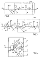
- the measurement of the system can be performed from a phase modulated ellipsometer shown in Figure 1. It comprises a phase modulator (input arm) and a polarizer (output arm) . It is then proposed to control in real time a process for producing thin layers (deposition or etching) from the kinetic measurement of components of the Mueller matrix of the system, or combinations or functions of these elements. It also makes it possible to characterize a non-depolarizing anisotropic medium according to the method described above.
- control is considered on a depolarizing system.
- the representation of the system by a matrix of Jones is then insufficient and it is necessary to resort to the matrix of Mueller.
- the ellipsometer comprises a polarization state generator. at the input and / or a polarimeter at the output.
- the input arm of the ellipsometer is shown diagrammatically in FIG. 2. It comprises a linear polarizer 120 and a coupled modulator 106 comprising two phase modulators 121 and 122 and a coupling system 123 of the partial polarizer and phase shifter type.
- the two phase modulators 121 and 122 have the same orientation and the coupling system 123 is interposed between them and transmits the incident beam 110 of the first phase modulator 121 to the second phase modulator 122.
- the orientations of the various elements are as follows.
- the incident beam 110 having a direction and a direction of propagation and an incident plane being defined from this direction of propagation and the sample 2, a mark is formed comprising a first axis x perpendicular to the direction of propagation and in the plane of incidence, a second axis y perpendicular to the plane of incidence and a third axis parallel to the direction of propagation and oriented in the same direction, this mark being direct.
- the polarizer 120 is then a perfect polarizer oriented along the y axis.
- the two phase modulators 121 and 122 are identical and oriented in the plane xy along directions respectively forming with the axis y, angles ⁇ 1 and ⁇ 2.
- the angles ⁇ 1 and ⁇ 2 are advantageously identical and preferably equal to ⁇ / 4.
- the coupling system 123 is oriented along the x axis.
- the incident beam 110 is polarized linearly by the polarizer 120, then undergoes a double modulation coupled due to the phase modulators 121. 122 and the coupling system 123.
- the coupling system 123 provides two functions: a partial polarization ( imperfect polarizer) and a phase shift, which modulate the four components of the Stokes S.
- a polarizer 120 such as the one sold under the name of "Glan Thomson polarizer” linearly polarizing the incident beam 110 and a coupled modulator 106 comprising a single modulator of phase 121 and a coupling system 161 of the partial polarizer and phase shifter operating in reflection.
- the phase modulator 121 is interposed between the polarizer 120 and the coupling system 161 so that it produces a first modulation of the polarized incident beam 110 and sends it to the coupling system 161, the latter returning the incident beam. 110 to the phase modulator 121 which produces a second modulation.
- the coupled modulator 106 also includes a mirror 162 disposed between the polarizer 120 and the modulator 121 which reflects the beam 111 modulated twice to the sample.
- the polarizer 120 is oriented along an axis y and the modulator 121 is oriented in a plane xy in a direction forming an angle ⁇ 3 with the axis x, ⁇ 3 being equal to 45 °
- the coupling system 161 is meanwhile oriented along the x axis, so as to allow a return of the incident beam 110 parallel to the go.
- the mirror 162 advantageously returns the beam 111 along the y axis perpendicular to x.
- the modulator 121 is advantageously an electro-optical modulator (Pockels cell). Such a modulator 121 allows external phase shift control and allows a bandwidth exceeding 100 MHz.
- the phase modulator 121 can also be a photoelastic modulator, which results in an extended wavelength range and a large optical window.
- the light source emits laser beams 113, 114 at several wavelengths.
- the ellipsometer then comprises a mobile mirror 126 for selecting the desired wavelength.
- the output arm shown in FIG. 4 advantageously comprises a splitter 130 of beams separating the measurement beam into at least four secondary beams 116-119. It also includes polarization analyzers 136-139 giving each of these secondary beams 116-119. a distinct polarization state and photodetectors 131-134 respectively detecting the intensities I1 to I4 of the secondary beams 116-119.
- the secondary beams 116-119 being four in number
- the associated polarization analyzers 136-139 are respectively nothing, a linear polarizer at 90 °, a linear polarizer at -45 ° and the association of a quarter-wave plate at 45 ° and a polarizer at 90 °.
- This Mueller ellipsometer allows the control of the processes according to the invention.
- many methods can be controlled with a simplified ellipsometric assembly, said intermediate. It is thus possible, for example, to use a modulator coupled in the input arm or else a single input phase modulator and an output polarimeter, each of these configurations making it possible to measure more than two coefficients related to the Mueller matrix. .
- the production methods referred to herein are essentially the plasma deposition of thin layers and multilayer structures or composition gradients (optical filters), or the etching (plasma) of microelectronic components. More generally, the proposed control method can be applied to other production processes using gases or metal-organic compounds (CVDs: Chemical Vapor Deposition and MOCVD) or to generalize to processes based on the use of sources or solid targets (cathodic sputtering, vacuum evaporation, molecular beam epitaxy ). In the latter case, the feedback from the ellipsometric measurements is not performed on a gas management, but on other control parameters (currents, temperature ).
- CVDs Chemical Vapor Deposition and MOCVD
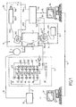
- the manufacturing facility comprises a plasma chamber 1 in which is placed the substrate 2 which is, for example, the original element of the semiconductor wafer to be manufactured. This substrate is fixed on a support 3.
- the pressure in the plasma chamber 1 is obtained by the effect of the pump 4, connected thereto by the pipe 5.
- the gas panel 6 feeds through the pipe 7, the Plasma chamber 1. It is connected to gas supplies respectively N 2 nitrogen, 62 ammonia NH 3 , 63 hydrogen H 2 , 64 methane CH 4 , 65 helium He, 66 silane SiH 4 , 67 with oxygen O 2 or nitrogen oxide N 2 O.
- Inputs 62 to 65 are each connected to line 7 via a flow meter 621, 631, 641, 651 and a valve 622, 632, 642.652.
- the silane feed 66 is connected to two flow meters 661 and 671 and two valves 662 and 672.
- An evacuation 8 to the sewers makes it possible to ensure the proper functioning of this gas panel.
- the elaboration of the layers on the substrate 2 in the plasma chamber 1 is controlled by means of an ellipsometer 9 composed of a transmission head 91 and a reception assembly 92.
- the transmission head 91 comprises a source 911 connected to an optical fiber 912 to an assembly consisting of a polarizer 913 and a phase modulator 914.
- the receiver assembly 92 comprises a polarizer-analyzer 921 connected by an optical fiber 922 to a monochromator 923 followed by a photodetector 924.
- the ellipsometer 9 is controlled by a processing unit 93 controlled by a computer 94.
- the processing unit 93 controls the polarizer 913 and the modulator 914, respectively by the electrical connections 931 and 932, and receives the signal from the detector 924 by the electrical connection 934. Its connection with the computer 94 is provided by the electrical connection 95.
- the gas panel 6 is controlled by a processing unit 10 to which it is connected by the connections 11.
- This processing unit 10 also controls, via the link 12, the pump 4 and / or the power of the generator. plasma. It is controlled by a microcomputer 13 which is itself connected to the microcomputer 94 via a link 14.
- the ellipsometer 9 makes it possible to obtain, through the processing unit 93 and the microcomputer 94, the physical and chemical characteristics of the layer being deposited on the substrate 2. This information is compared with the characteristics of the product to be manufactured (and possibly to their variation as a function of time) which were previously stored in the computer 94.
- the result of this comparison controls via the connection 14, the instructions provided by the computer 13 to the processing unit 10 which determines the nature and the concentration of the gases introduced by the control panel 6 into the chamber. plasma 2.
- the processing unit 93 and the computer 94 are programmed so that the control of the properties of the layer deposited on the sample 2 can be achieved by a small number of previously determined parameters.
Landscapes
- Immunology (AREA)
- Life Sciences & Earth Sciences (AREA)
- Pathology (AREA)
- Analytical Chemistry (AREA)
- Biochemistry (AREA)
- General Health & Medical Sciences (AREA)
- General Physics & Mathematics (AREA)
- Health & Medical Sciences (AREA)
- Physics & Mathematics (AREA)
- Chemical & Material Sciences (AREA)
- Investigating Or Analysing Materials By Optical Means (AREA)
- Length Measuring Devices By Optical Means (AREA)
- Glass Compositions (AREA)
- Preparation Of Compounds By Using Micro-Organisms (AREA)
- Chemical Vapour Deposition (AREA)
- Physical Vapour Deposition (AREA)
- Electroluminescent Light Sources (AREA)
- Physical Deposition Of Substances That Are Components Of Semiconductor Devices (AREA)
- Crystals, And After-Treatments Of Crystals (AREA)
Claims (19)
- Steuerungsverfahren für die Herstellung eines anisotropen und/oder depolarisierenden Objekts (2), bei welchem:- eine Ellipsometriemessung an dem Objekt durchgeführt wird, welche durch ihre Müller-Matrix dargestellt ist,- in Echtzeit die Herstellung in Abhängigkeit von der Ellipsometriemessung gesteuert wird,dadurch gekennzeichnet, dass vor der Herstellung des Objekts gewisse Parameter der Müller-Matrix bestimmt werden, welche zur Charakterisierung der Herstellung geeignet sind, und dass einzelne dieser Parameter während der Herstellung aus der Ellipsometriemessung extrahiert werden, wobei die Parameter zahlenmäßig wenigstens zwei sind und sich in den Ellipsometriewinkeln Ψ und Δ und den trigonometrischen Funktionen derselben unterscheiden.
- Steuerungsverfahren für die Herstellung eines Objekts nach Anspruch 1, dadurch gekennzeichnet, dass das Objekt anisotrop ist.
- Steuerungsverfahren für die Herstellung eines Objekts nach einem der Ansprüche 1 oder 2, dadurch gekennzeichnet, dass das Objekt depolarisierend ist.
- Steuerungsverfahren für die Herstellung eines Objekts nach einem der Ansprüche 1-3, dadurch gekennzeichnet, dass das Objekt Brechungsphänomene induziert.
- Steuerungsverfahren für die Herstellung eines Objekts nach einem der Ansprüche 1-4, dadurch gekennzeichnet, dass die zur Charakterisierung der Herstellung geeigneten Parameter eine Linearkombination von Zeilen der Müller-Matrix sind.
- Steuerungsverfahren für die Herstellung eines Objekts nach einem der Ansprüche 1-4, dadurch gekennzeichnet, dass die zur Charakterisierung der Herstellung geeigneten Parameter eine Linearkombination von Spalten der Müller-Matrix sind.
- Steuerungsverfahren nach einem der Ansprüche 1-6, dadurch gekennzeichnet, dass das hergestellte Objekt eine Halbleiterkomponente ist.
- Steuerungsverfahren für die Herstellung eines Objekts nach Anspruch 7, dadurch gekennzeichnet, dass die Ellipsometriemessung eine Schicht während ihrer Abscheidung charakterisiert.
- Steuerungsverfahren für die Herstellung eines Objekts nach Anspruch 7, dadurch gekennzeichnet, dass die Ellipsometriemessung eine Schicht während ihrer Ätzung charakterisiert.
- Steuerungsverfahren für die Herstellung eines Objekts nach einem der Ansprüche 8 oder 9, dadurch gekennzeichnet, dass die Ellipsometriemessung die Zusammensetzung der Schicht charakterisiert.
- Steuerungsverfahren für die Herstellung eines Objekts nach einem der Ansprüche 8 oder 9, dadurch gekennzeichnet, dass die Ellipsometriemessung die Dicke der Schicht charakterisiert.
- Steuerungsverfahren für die Herstellung eines Objekts nach einem der Ansprüche 1-11, dadurch gekennzeichnet, dass die Herstellung durch Dissoziation von Gas erfolgt und sie durch ein Gaspanel (6) gesteuert wird.
- Steuerungsverfahren für die Herstellung eines Objekts nach Anspruch 12, dadurch gekennzeichnet, dass das Gaspanel einen Plasmareaktor (1) versorgt.
- Steuerungsverfahren für die Herstellung eines Objekts nach einem der Ansprüche 12 oder 13, dadurch gekennzeichnet, dass das Gaspanel die Gasdurchflüsse steuert.
- Anlage zur Herstellung eines anisotropen und/oder depolarisierenden Objekts, umfassend ein Ellipsometer, welches die Durchführung einer Messung an dem Objekt (2) ermöglicht, welche durch ihre Müller-Matrix dargestellt ist, dadurch gekennzeichnet, dass das Ellipsometer Mittel umfasst, um in Echtzeit Parameter zu messen, welche vor der Herstellung des Objekts bestimmt und zur Charakterisierung der Herstellung geeignet sind, wobei die Parameter zahlenmäßig wenigstens zwei sind und sich in den Ellipsometriewinkeln ψ und Δ und den trigonometrischen Funktionen derselben unterscheiden, wobei die Parameter Parameter der Müller-Matrix sind.
- Anlage zur Herstellung eines Objekts nach Anspruch 15, dadurch gekennzeichnet, dass sie durch Dissoziation von Gas erfolgt.
- Anlage zur Herstellung eines Objekts nach einem der Ansprüche 15 und 16, dadurch gekennzeichnet, dass sie am Eingang einen gekoppelten Modulator (106) umfasst.
- Anlage zur Herstellung eines Objekts nach einem der Ansprüche 15-17, dadurch gekennzeichnet, dass sie am Ausgang ein Polarimeter umfasst.
- Anlage zur Herstellung eines Objekts nach einem der Ansprüche 15-18, dadurch gekennzeichnet, dass sie zum Einsatz des Verfahrens nach einem der Ansprüche 1-14 ausgestaltet ist.
Applications Claiming Priority (3)
| Application Number | Priority Date | Filing Date | Title |
|---|---|---|---|
| FR9807594A FR2779825B1 (fr) | 1998-06-16 | 1998-06-16 | Procede et dispositif de commande de la fabrication d'un composant en couche mince a partir d'une dissociation de gaz |
| FR9807594 | 1998-06-16 | ||
| PCT/FR1999/001394 WO1999066286A1 (fr) | 1998-06-16 | 1999-06-11 | Procede ellipsometrique et dispositif de commande de la fabrication d'un composant en couche mince |
Publications (2)
| Publication Number | Publication Date |
|---|---|
| EP1086355A1 EP1086355A1 (de) | 2001-03-28 |
| EP1086355B1 true EP1086355B1 (de) | 2006-06-07 |
Family
ID=9527463
Family Applications (1)
| Application Number | Title | Priority Date | Filing Date |
|---|---|---|---|
| EP99923728A Expired - Lifetime EP1086355B1 (de) | 1998-06-16 | 1999-06-11 | Ellipsometrisches verfahren und kontrollvorrichtung zur herstellung eines dünnschichtbauelements |
Country Status (8)
| Country | Link |
|---|---|
| US (1) | US6914675B1 (de) |
| EP (1) | EP1086355B1 (de) |
| JP (1) | JP2002518665A (de) |
| AT (1) | ATE329224T1 (de) |
| AU (1) | AU4049499A (de) |
| DE (1) | DE69931779T2 (de) |
| FR (1) | FR2779825B1 (de) |
| WO (1) | WO1999066286A1 (de) |
Families Citing this family (5)
| Publication number | Priority date | Publication date | Assignee | Title |
|---|---|---|---|---|
| FR2818376B1 (fr) * | 2000-12-18 | 2003-03-28 | Centre Nat Rech Scient | Dispositif de visualisation bidimensionnelle ellipsometrique d'un echantillon, procede de visualisation et procede de mesure ellipsometrique avec resolution spatiale |
| US7830512B2 (en) * | 2008-03-14 | 2010-11-09 | J.A. Woollam Co., Inc. | System and method for controlling intensity of a beam of electromagnetic radiation in ellipsometers and polarimeters |
| US8139234B2 (en) * | 2005-10-26 | 2012-03-20 | Dube George | Method and apparatus for measuring optical extinction in a thin film during its deposition |
| US9400246B2 (en) * | 2011-10-11 | 2016-07-26 | Kla-Tencor Corporation | Optical metrology tool equipped with modulated illumination sources |
| US11313727B2 (en) * | 2020-08-17 | 2022-04-26 | National Tsing Hua University | EUV spectroscopic polarimeter |
Family Cites Families (13)
| Publication number | Priority date | Publication date | Assignee | Title |
|---|---|---|---|---|
| US4941138A (en) * | 1986-10-21 | 1990-07-10 | Nakamichi Corporation | Method and an apparatus for measuring optical characteristics of an optical disk |
| US5131752A (en) * | 1990-06-28 | 1992-07-21 | Tamarack Scientific Co., Inc. | Method for film thickness endpoint control |
| US5277747A (en) * | 1992-09-15 | 1994-01-11 | Bell Communications Research, Inc. | Extraction of spatially varying dielectric function from ellipsometric data |
| FR2731074B1 (fr) * | 1995-02-27 | 1997-05-16 | Instruments Sa | Procede de mesure ellipsometrique, ellipsometre et dispositif de controle d'elaboration de couches les mettant en oeuvre |
| US6391690B2 (en) * | 1995-12-14 | 2002-05-21 | Seiko Epson Corporation | Thin film semiconductor device and method for producing the same |
| US5822035A (en) * | 1996-08-30 | 1998-10-13 | Heidelberg Engineering Optische Messysteme Gmbh | Ellipsometer |
| FR2755254B1 (fr) * | 1996-10-25 | 1999-01-15 | Centre Nat Rech Scient | Composant optique de modulation, polarimetre et ellipsometre de mueller comprenant un tel composant optique, procede de calibrage de cet ellipsometre et procede de mesure ellipsometrique |
| JPH10160576A (ja) * | 1996-11-27 | 1998-06-19 | Yuureka:Kk | 偏光解析装置の波長変更方法 |
| US6128084A (en) * | 1997-06-11 | 2000-10-03 | Matsushita Electronics Corporation | Evaluation method of semiconductor layer, method for fabricating semiconductor device, and storage medium |
| US6081334A (en) * | 1998-04-17 | 2000-06-27 | Applied Materials, Inc | Endpoint detection for semiconductor processes |
| US6052188A (en) * | 1998-07-08 | 2000-04-18 | Verity Instruments, Inc. | Spectroscopic ellipsometer |
| CA2380492A1 (en) * | 1999-07-27 | 2001-02-01 | Thomas E. Furtak | Parallel detecting, spectroscopic ellipsometers/polarimeters |
| US6485872B1 (en) * | 1999-12-03 | 2002-11-26 | Mks Instruments, Inc. | Method and apparatus for measuring the composition and other properties of thin films utilizing infrared radiation |
-
1998
- 1998-06-16 FR FR9807594A patent/FR2779825B1/fr not_active Expired - Fee Related
-
1999
- 1999-06-11 DE DE69931779T patent/DE69931779T2/de not_active Expired - Fee Related
- 1999-06-11 AT AT99923728T patent/ATE329224T1/de not_active IP Right Cessation
- 1999-06-11 WO PCT/FR1999/001394 patent/WO1999066286A1/fr not_active Ceased
- 1999-06-11 US US09/719,825 patent/US6914675B1/en not_active Expired - Fee Related
- 1999-06-11 EP EP99923728A patent/EP1086355B1/de not_active Expired - Lifetime
- 1999-06-11 JP JP2000555062A patent/JP2002518665A/ja active Pending
- 1999-06-11 AU AU40494/99A patent/AU4049499A/en not_active Abandoned
Also Published As
| Publication number | Publication date |
|---|---|
| FR2779825A1 (fr) | 1999-12-17 |
| FR2779825B1 (fr) | 2000-09-01 |
| AU4049499A (en) | 2000-01-05 |
| DE69931779D1 (de) | 2006-07-20 |
| WO1999066286A1 (fr) | 1999-12-23 |
| DE69931779T2 (de) | 2007-05-16 |
| US6914675B1 (en) | 2005-07-05 |
| ATE329224T1 (de) | 2006-06-15 |
| JP2002518665A (ja) | 2002-06-25 |
| EP1086355A1 (de) | 2001-03-28 |
Similar Documents
| Publication | Publication Date | Title |
|---|---|---|
| EP0870180B1 (de) | Optisches bauelement zur polarisationsmodulation, und dessen verwendung in einem polarimeter oder ellipsometer | |
| EP0663590B1 (de) | Moduliertes Spektralellipsometer | |
| FR2937732A1 (fr) | Dispositif et procede de mesures polarimetriques spectroscopiques dans le domaine visible et proche infrarouge | |
| FR2737572A1 (fr) | Ellipsometre multi-detecteurs et procede de mesure ellipsometrique multi-detecteurs | |
| FR2496344A1 (fr) | Transformateur de polarisation | |
| Johs et al. | Recent developments in spectroscopic ellipsometry for in-situ applications | |
| FR2876184A1 (fr) | Procede de determination des conditions de la formation de film | |
| EP1086355B1 (de) | Ellipsometrisches verfahren und kontrollvorrichtung zur herstellung eines dünnschichtbauelements | |
| FR2731074A1 (fr) | Procede de mesure ellipsometrique, ellipsometre et dispositif de controle d'elaboration de couches les mettant en oeuvre | |
| FR2616269A1 (fr) | Dispositif de test pour la mise en oeuvre d'un procede de realisation de dispositifs semiconducteurs | |
| EP0237415B1 (de) | Vorrichtung zur spektralphotometrischen Ellipsometrie mit Verwendung optischer Fasern | |
| US6731386B2 (en) | Measurement technique for ultra-thin oxides | |
| FR2880129A1 (fr) | Caracterisation metrologique de circuits de microelectronique | |
| FR2555308A1 (fr) | Tete photometrique et applications a des dispositifs de controle de l'epaisseur d'une couche mince | |
| FR2812941A1 (fr) | Procede de controle en temps reel de l'elaboration d'une structure en couches minces par mesure elipsometrique | |
| JP2004101235A (ja) | 半導体の歪量を測定する装置及び方法、半導体の歪量分布を測定する装置及び方法、並びに半導体製造装置及び方法 | |
| US20250137773A1 (en) | Film thickness measurement device | |
| Arsac | Development of optical monitoring strategies for the fabrication of optical thin-film filters with physical vapor deposition technologies | |
| WO2002027361A1 (fr) | Procede optique de diffraction de la lumiere, systeme optique et dispositif correspondants | |
| EP4490991A1 (de) | Verfahren zur dickenkorrektur einer piezoelektrischen schicht | |
| Li et al. | Method of collecting pure vibrational absorption spectra of amorphous thin films | |
| Aspnes | Recent Advances in Optical Characterization of Thin Films by Spectroscopic Ellipsometry | |
| FR2501861A1 (fr) | Ellipsometre comportant un prisme a reflexions totales | |
| FR2891904A1 (fr) | Procede de mesure optique d'une couche en temps reel, en incidence normale | |
| FR2771850A1 (fr) | Procede de fabrication de dispositifs en couches minces utilisant la technique de la reflectance anisotrope |
Legal Events
| Date | Code | Title | Description |
|---|---|---|---|
| PUAI | Public reference made under article 153(3) epc to a published international application that has entered the european phase |
Free format text: ORIGINAL CODE: 0009012 |
|
| 17P | Request for examination filed |
Effective date: 20010116 |
|
| AK | Designated contracting states |
Kind code of ref document: A1 Designated state(s): AT BE CH CY DE DK ES FI FR GB GR IE IT LI LU MC NL PT SE |
|
| 17Q | First examination report despatched |
Effective date: 20050419 |
|
| GRAP | Despatch of communication of intention to grant a patent |
Free format text: ORIGINAL CODE: EPIDOSNIGR1 |
|
| GRAS | Grant fee paid |
Free format text: ORIGINAL CODE: EPIDOSNIGR3 |
|
| GRAA | (expected) grant |
Free format text: ORIGINAL CODE: 0009210 |
|
| PGFP | Annual fee paid to national office [announced via postgrant information from national office to epo] |
Ref country code: CH Payment date: 20060529 Year of fee payment: 8 |
|
| AK | Designated contracting states |
Kind code of ref document: B1 Designated state(s): AT BE CH CY DE DK ES FI FR GB GR IE IT LI LU MC NL PT SE |
|
| PG25 | Lapsed in a contracting state [announced via postgrant information from national office to epo] |
Ref country code: NL Free format text: LAPSE BECAUSE OF FAILURE TO SUBMIT A TRANSLATION OF THE DESCRIPTION OR TO PAY THE FEE WITHIN THE PRESCRIBED TIME-LIMIT Effective date: 20060607 Ref country code: IT Free format text: LAPSE BECAUSE OF FAILURE TO SUBMIT A TRANSLATION OF THE DESCRIPTION OR TO PAY THE FEE WITHIN THE PRESCRIBED TIME-LIMIT;WARNING: LAPSES OF ITALIAN PATENTS WITH EFFECTIVE DATE BEFORE 2007 MAY HAVE OCCURRED AT ANY TIME BEFORE 2007. THE CORRECT EFFECTIVE DATE MAY BE DIFFERENT FROM THE ONE RECORDED. Effective date: 20060607 Ref country code: IE Free format text: LAPSE BECAUSE OF FAILURE TO SUBMIT A TRANSLATION OF THE DESCRIPTION OR TO PAY THE FEE WITHIN THE PRESCRIBED TIME-LIMIT Effective date: 20060607 Ref country code: FI Free format text: LAPSE BECAUSE OF FAILURE TO SUBMIT A TRANSLATION OF THE DESCRIPTION OR TO PAY THE FEE WITHIN THE PRESCRIBED TIME-LIMIT Effective date: 20060607 Ref country code: AT Free format text: LAPSE BECAUSE OF FAILURE TO SUBMIT A TRANSLATION OF THE DESCRIPTION OR TO PAY THE FEE WITHIN THE PRESCRIBED TIME-LIMIT Effective date: 20060607 |
|
| REG | Reference to a national code |
Ref country code: GB Ref legal event code: FG4D Free format text: NOT ENGLISH |
|
| PGFP | Annual fee paid to national office [announced via postgrant information from national office to epo] |
Ref country code: DE Payment date: 20060608 Year of fee payment: 8 |
|
| REG | Reference to a national code |
Ref country code: CH Ref legal event code: EP |
|
| PGFP | Annual fee paid to national office [announced via postgrant information from national office to epo] |
Ref country code: FR Payment date: 20060629 Year of fee payment: 8 |
|
| PG25 | Lapsed in a contracting state [announced via postgrant information from national office to epo] |
Ref country code: MC Free format text: LAPSE BECAUSE OF NON-PAYMENT OF DUE FEES Effective date: 20060630 Ref country code: BE Free format text: LAPSE BECAUSE OF NON-PAYMENT OF DUE FEES Effective date: 20060630 |
|
| REG | Reference to a national code |
Ref country code: IE Ref legal event code: FG4D Free format text: LANGUAGE OF EP DOCUMENT: FRENCH |
|
| REF | Corresponds to: |
Ref document number: 69931779 Country of ref document: DE Date of ref document: 20060720 Kind code of ref document: P |
|
| REG | Reference to a national code |
Ref country code: CH Ref legal event code: NV Representative=s name: KIRKER & CIE SA |
|
| PGFP | Annual fee paid to national office [announced via postgrant information from national office to epo] |
Ref country code: GB Payment date: 20060801 Year of fee payment: 8 |
|
| PG25 | Lapsed in a contracting state [announced via postgrant information from national office to epo] |
Ref country code: SE Free format text: LAPSE BECAUSE OF FAILURE TO SUBMIT A TRANSLATION OF THE DESCRIPTION OR TO PAY THE FEE WITHIN THE PRESCRIBED TIME-LIMIT Effective date: 20060907 Ref country code: DK Free format text: LAPSE BECAUSE OF FAILURE TO SUBMIT A TRANSLATION OF THE DESCRIPTION OR TO PAY THE FEE WITHIN THE PRESCRIBED TIME-LIMIT Effective date: 20060907 |
|
| PG25 | Lapsed in a contracting state [announced via postgrant information from national office to epo] |
Ref country code: ES Free format text: LAPSE BECAUSE OF FAILURE TO SUBMIT A TRANSLATION OF THE DESCRIPTION OR TO PAY THE FEE WITHIN THE PRESCRIBED TIME-LIMIT Effective date: 20060918 |
|
| GBT | Gb: translation of ep patent filed (gb section 77(6)(a)/1977) |
Effective date: 20060920 |
|
| PG25 | Lapsed in a contracting state [announced via postgrant information from national office to epo] |
Ref country code: PT Free format text: LAPSE BECAUSE OF FAILURE TO SUBMIT A TRANSLATION OF THE DESCRIPTION OR TO PAY THE FEE WITHIN THE PRESCRIBED TIME-LIMIT Effective date: 20061107 |
|
| NLV1 | Nl: lapsed or annulled due to failure to fulfill the requirements of art. 29p and 29m of the patents act | ||
| REG | Reference to a national code |
Ref country code: IE Ref legal event code: FD4D |
|
| PLBE | No opposition filed within time limit |
Free format text: ORIGINAL CODE: 0009261 |
|
| STAA | Information on the status of an ep patent application or granted ep patent |
Free format text: STATUS: NO OPPOSITION FILED WITHIN TIME LIMIT |
|
| 26N | No opposition filed |
Effective date: 20070308 |
|
| BERE | Be: lapsed |
Owner name: CENTRE NATIONAL DE LA RECHERCHE SCIENTIFIQUE Effective date: 20060630 |
|
| REG | Reference to a national code |
Ref country code: CH Ref legal event code: PL |
|
| GBPC | Gb: european patent ceased through non-payment of renewal fee |
Effective date: 20070611 |
|
| REG | Reference to a national code |
Ref country code: FR Ref legal event code: ST Effective date: 20080229 |
|
| PG25 | Lapsed in a contracting state [announced via postgrant information from national office to epo] |
Ref country code: LI Free format text: LAPSE BECAUSE OF NON-PAYMENT OF DUE FEES Effective date: 20070630 Ref country code: GR Free format text: LAPSE BECAUSE OF FAILURE TO SUBMIT A TRANSLATION OF THE DESCRIPTION OR TO PAY THE FEE WITHIN THE PRESCRIBED TIME-LIMIT Effective date: 20060908 Ref country code: DE Free format text: LAPSE BECAUSE OF NON-PAYMENT OF DUE FEES Effective date: 20080101 Ref country code: CH Free format text: LAPSE BECAUSE OF NON-PAYMENT OF DUE FEES Effective date: 20070630 |
|
| PG25 | Lapsed in a contracting state [announced via postgrant information from national office to epo] |
Ref country code: GB Free format text: LAPSE BECAUSE OF NON-PAYMENT OF DUE FEES Effective date: 20070611 |
|
| PG25 | Lapsed in a contracting state [announced via postgrant information from national office to epo] |
Ref country code: LU Free format text: LAPSE BECAUSE OF NON-PAYMENT OF DUE FEES Effective date: 20060611 |
|
| PG25 | Lapsed in a contracting state [announced via postgrant information from national office to epo] |
Ref country code: FR Free format text: LAPSE BECAUSE OF NON-PAYMENT OF DUE FEES Effective date: 20070702 |
|
| PG25 | Lapsed in a contracting state [announced via postgrant information from national office to epo] |
Ref country code: CY Free format text: LAPSE BECAUSE OF FAILURE TO SUBMIT A TRANSLATION OF THE DESCRIPTION OR TO PAY THE FEE WITHIN THE PRESCRIBED TIME-LIMIT Effective date: 20060607 |