EP0759836B1 - Rasiersystem - Google Patents
Rasiersystem Download PDFInfo
- Publication number
- EP0759836B1 EP0759836B1 EP95919825A EP95919825A EP0759836B1 EP 0759836 B1 EP0759836 B1 EP 0759836B1 EP 95919825 A EP95919825 A EP 95919825A EP 95919825 A EP95919825 A EP 95919825A EP 0759836 B1 EP0759836 B1 EP 0759836B1
- Authority
- EP
- European Patent Office
- Prior art keywords
- shaving
- annular
- blade unit
- facet
- facets
- Prior art date
- Legal status (The legal status is an assumption and is not a legal conclusion. Google has not performed a legal analysis and makes no representation as to the accuracy of the status listed.)
- Expired - Lifetime
Links
- 230000000153 supplemental effect Effects 0.000 claims abstract description 27
- 239000003082 abrasive agent Substances 0.000 claims description 11
- 238000000034 method Methods 0.000 claims description 9
- 229910052751 metal Inorganic materials 0.000 claims description 4
- 239000002184 metal Substances 0.000 claims description 4
- 238000004519 manufacturing process Methods 0.000 claims description 2
- 238000005520 cutting process Methods 0.000 description 7
- 229910000831 Steel Inorganic materials 0.000 description 2
- TWNQGVIAIRXVLR-UHFFFAOYSA-N oxo(oxoalumanyloxy)alumane Chemical compound O=[Al]O[Al]=O TWNQGVIAIRXVLR-UHFFFAOYSA-N 0.000 description 2
- 238000003825 pressing Methods 0.000 description 2
- 229910052594 sapphire Inorganic materials 0.000 description 2
- 239000010980 sapphire Substances 0.000 description 2
- 238000009987 spinning Methods 0.000 description 2
- 239000010959 steel Substances 0.000 description 2
- 239000004677 Nylon Substances 0.000 description 1
- 239000004743 Polypropylene Substances 0.000 description 1
- 238000000576 coating method Methods 0.000 description 1
- 239000011888 foil Substances 0.000 description 1
- 239000000463 material Substances 0.000 description 1
- 150000004767 nitrides Chemical class 0.000 description 1
- 229920001778 nylon Polymers 0.000 description 1
- 229920000642 polymer Polymers 0.000 description 1
- -1 polypropylene Polymers 0.000 description 1
- 229920001155 polypropylene Polymers 0.000 description 1
Images

Classifications
-
- B—PERFORMING OPERATIONS; TRANSPORTING
- B26—HAND CUTTING TOOLS; CUTTING; SEVERING
- B26B—HAND-HELD CUTTING TOOLS NOT OTHERWISE PROVIDED FOR
- B26B21/00—Razors of the open or knife type; Safety razors or other shaving implements of the planing type; Hair-trimming devices involving a razor-blade; Equipment therefor
- B26B21/08—Razors of the open or knife type; Safety razors or other shaving implements of the planing type; Hair-trimming devices involving a razor-blade; Equipment therefor involving changeable blades
- B26B21/14—Safety razors with one or more blades arranged transversely to the handle
- B26B21/20—Safety razors with one or more blades arranged transversely to the handle involving blades with more than two cutting edges; involving disc blades
-
- B—PERFORMING OPERATIONS; TRANSPORTING
- B26—HAND CUTTING TOOLS; CUTTING; SEVERING
- B26B—HAND-HELD CUTTING TOOLS NOT OTHERWISE PROVIDED FOR
- B26B21/00—Razors of the open or knife type; Safety razors or other shaving implements of the planing type; Hair-trimming devices involving a razor-blade; Equipment therefor
- B26B21/08—Razors of the open or knife type; Safety razors or other shaving implements of the planing type; Hair-trimming devices involving a razor-blade; Equipment therefor involving changeable blades
- B26B21/14—Safety razors with one or more blades arranged transversely to the handle
- B26B21/22—Safety razors with one or more blades arranged transversely to the handle involving several blades to be used simultaneously
- B26B21/222—Safety razors with one or more blades arranged transversely to the handle involving several blades to be used simultaneously with the blades moulded into, or attached to, a changeable unit
Definitions
- This invention relates to shaving systems of the wet shave type, and more particularly to shaving systems that employ blade structures with annular cutting edge structures.
- a number of shaving systems with blade structures that have annular cutting edge structures have been proposed, see for example, Ackerman U.S. Patent No. 2,614,321; Musso U.S. Patent No. 3,465,436; Scholin U.S. Patent No. 3,702,026; Cerier U.S. Patent No. 4,807,360; Trotta U.S. Patent No. 4,875,288; and Welsh U.S. Patent No. 4,964,214; Jacobson U.S. Patent No. 5,031,317; Lazarshik et al. U.S. Patent No. 5,088,195; and PCT Application No. WO-9300204.
- shaving characteristics of such shaving systems have not been entirely satisfactory.
- U.S. Patent No. 5,088,195 discloses a foil sheet with aperatured cutting edges having a single top facet outwardly and upwardly deformed to form the facet surfaces that define an ultimate tip sharply angled with respect to the shaving plane.
- PCT Application WO-9300204 discloses a wedged shaving edge on a straight razor blade.
- U.S. Patent Nos. 4,875,288 and 5,031,317 disclose tubular blade units with apertured cutting edges having a single top facet converging with lower surface of the blade to form tip of the shaving edge.
- a shaving system of the wet shave type including a housing and at least one blade unit secured to said housing, said blade unit having an aperture defining an annular sharpened shaving edge defined by a main facet and supplemental facets extending from said main facet to define an annular ultimate tip, characterized in that said annular sharpened edge is further defined by another main facet that converges with said main facet at an angle of less than 40°, said supplemental facets converging at an included angle greater than that of said main facets portions and less than 60°, said annular ultimate tip being disposed within a boundary region defined by extensions of said main facets and defining a shaving plane and the bisector of an included angle defined by said supplemental facets being disposed at a shaving angle in a range of 15-35° to said shaving plane.
- the blade structure may take a variety of forms and the aperture may be of circular, elongated or other shape.
- the aperture has a width dimension (the distance between opposed sharpened edges of the same aperture) of less than one centimeter; the radial length dimension of the main facet portions is at least about twice the radial length of the contiguous supplemental facet portions; and each supplemental facet portion has a radial length of less than about 0.3 millimeter.
- the structure is a metal blade member that has a generally tubular upstanding body portion of predetermined height that defines a central aperture, and an integral, inwardly facing flange is provided at its upper end on which the annular sharpened shaving edge is formed.
- the shaving angle (the angle between the shaving plane and the bisector of the sharpened edge) is in the range of 20-32°
- the ultimate tip is defined by supplemental facets that have an included angle in the range of 25-40°
- the ultimate tip has a radius of less than 1,000 angstroms.
- the support structure has at least ten apertures in which corresponding blade members are disposed, and the support structure includes biasing structure that permits the individual blade members to move relative to the support structure independently of one another between spaced limiting structure on the support structure which cooperates with stop structure integral with the blade members.
- a method of manufacturing a razor blade including providing a blade unit with an annular body portion and an annular flange at one end of said annular body portion that extends radially inward from said body portion, said method characterized by disposing said blade unit on a cylindrical mandrel of abrasive material that has an inclined facet at its upper end such that the inner surface of said inwardly facing flange is juxtaposed with and supported by said inclined facet, providing another abrasive material adjacent the outer surface of said flange portion, and producing relative motion between said another abrasive material and said blade unit to rotate said blade unit on said mandrel while said inner surface of said flange portion is in engagement with said mandrel facet and the outer surface of said flange is in engagement with said another abrasive material to abrasively shape and form facets on said inner and outer surfaces of said flange portion to provide an annular shaving edge on said blade unit.
- the annular shaving edge has a width dimension of less than one centimeter, and the abrasive structure is driven in rotation at a speed of at least 600 RPM.
- the rotational axis of the abrasive structure is generally perpendicular to the mandrel axis and in another embodiment these axes are generally parallel.
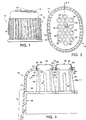
- the shaving system 10 shown in Figs. 1 and 2 is of the type shown in Jacobson U.S. Patent No. 5,031,317, and includes polypropylene housing 12 with side wall 14 and top wall 16. Side wall 14 is provided with elongated ribs 18 on its exterior surface which serve as grasping structure for the shaving system.
- the top wall 14 is provided with an array of apertures 20 which receive tubular blade units 22.
- Each blade unit 22, as indicated in Fig. 3 has a generally tubular wall 24 defining a central aperture therethrough.
- An integrally formed flange 28 extends inwardly from the upper end of tubular wall 24 and has an annular, inwardly directed, cutting edge 30 at a free end thereof.
- a second integrally formed flange 32 extends outwardly from the lower end of the tubular wall and is adapted to be disposed against an undersurface 34 of top wall 16 of housing 12.
- the blade units 22 are preferably of metal, such as treated steel.
- the shaving system includes a nylon base member 36 attached to and contained within housing 12.
- the undersurface 34 of housing 12 and the upper surface 38 of base member 36 are disposed generally parallel to and spaced from each other.
- Resilient spring fingers 40 extend upwardly from the upper surface 38 of base member 36 and extend into the blade units 22 and bias the lower flanges 32 upwardly against the inner surface 34 of housing top wall 16.
- Rigid protrusions 42 extend from the upper surface 38 of base member 36 with the spring fingers 40 and the protrusions 42 are arranged in general alignment with the housing apertures 20.
- Each razor blade unit 22 is disposed in a corresponding aperture 20 in the housing top wall with three spring fingers 40 extending into the lower end of each tubular blade unit 22.
- the rigid protrusions 42 are provided with flat surfaces 44 at their free upper ends that are adapted to limit the downward movement of the blade units 22 and spring fingers 40 have inclined outboard surfaces 48.
- each blade unit 22 is of 0.1 millimeter thickness steel and has a cylindrical body portion 24 of about 6.7 millimeters outer diameter and about 2.5 millimeters height; upper flange 28 that is inclined upwardly at an angle of 30° with cutting edge 30 defining a circle of about five millimeters diameter; and horizontal lower flange 32 that has an outer edge of about 7.5 millimeters diameter.
- FIG. 4 A further enlarged view of the portion of cutting edge 30 is shown in Fig. 4.
- the ultimate tip 46 of each sharpened shaving edge 30 has a radius of about 600 angstroms and defines shaving plane 50 and edge 30 and tip 46 are defined by supplemental facet surfaces 52, 54 that are disposed at an angle of about 28° to each other, surface 52 being disposed at an angle of about 10° to shaving plane 50 and surface 54 being disposed at an angle of about 38° to plane 50.
- Adjacent to and contiguous with upper supplemental facet 52 is upper main facet 56 that is disposed at an angle of about 14° to shaving plane 50 and adjacent to and contiguous with lower supplemental facet 54 is lower main facet 58 disposed at an angle of about 33° to shaving plane 50.
- the shaving angle 60 (the angle between the bisector 62 of the facets 52, 54 that define the ultimate tip 46 and shaving plane 50) is about 24°, and the bisector 64 of the main facets 56, 58 is disposed at an angle 66 of about 23.5° to shaving plane 50.
- Blade unit 22 is sharpened in a two stage sharpening operation.
- an unsharpened blade unit 22 with 30° conical upper portion 68 is placed on a sapphire mandrel 70 that has a cylindrical body 72 of about six millimeters diameter and a 30° facet 74 at its upper end.
- Axis 76 of mandrel 70 is disposed at an angle of 15° to the face 78 of aluminum oxide abrasive wheel 80 of about fifteen centimeters diameter. Wheel 80 is rotated at 1700 RPM about axis 82.
- wheel 80 With its surface 78 in pressing engagement with upper flange 28 abrades conical portion 68 and causes blade unit 22 to spin on sapphire mandrel 70 and the wheel pressure forcing flange 28 down in flexing action against mandrel facet 74 as blade unit 22 is spinning to form lower grind (main) facet 58.
- wheel surface 84 interacts with the upper surface of flange 28 to form upper grind (main) facet 56.
- Facet 56 forms an angle of about 14° to shaving plane 50; facet 58 is disposed at an angle of about 33° to plane 50; the included angle between facets 56 and 58 about being 19° and bisector 64 being disposed at about 23.5° to plane 50 (angle 66 - Fig. 4).
- the ground blade unit 22 is then placed on a 15 micron grit cubic boride nitride (CBN) finish mandrel 86 of the same diameter as mandrel 70 and with facet 88 at a 33° angle.
- CBN cubic boride nitride
- the axis 90 of finish mandrel 86 is offset 83° to the axis 92 of rotation of Corfam strop finish cylinder 94.
- Cylinder 94 is about fifteen centimeters in length and about eighteen centimeters diameter and loose one micron aluminum oxide abrasive is applied to its surface.
- the ground blade unit 22 is passed across the abrasively loaded finish strop 94 as that strop 94 is rotated at 1000 RPM to form supplemental facets 52, 54.
- the rotation of cylinder 94 with its surface 96 in pressing engagement with upper facet 56 causes blade unit 22 to spin on finish mandrel 86 about axis 90 and the cylinder pressure of cylinder 94 forces facet 58 down in flexing action against mandrel facet 88 as blade unit 22 is spinning to form supplemental facet 54.
- cylinder surface 96 interacts with upper facet 56 to form supplemental facet 52.
- Upper supplemental facet 52 has a length of about two micrometers and is disposed at an angle of about 10° to plane 50 and lower supplemental facet 54 has a length of about four micrometers and is disposed at an angle of about 38° to plane 50, the included angle between facets 52, 54 being about 28° and bisector 62 being disposed at about 24° to plane 50.
- the angles of supplemental facets 52, 54 are measured at approximately 1.5 micrometers from tip 30 and the main facet angles are measured at about 0.1 millimeter inch from tip 30.
- the resulting shaving angle 60 is about 24°.
- Coatings of metal and/or polymer may be applied to the sharpened edges as desired, and the processed blade units 22 are assembled in shaving system 10.
- the blade units 22 are mounted on the spring fingers 40 of the base member 36 (or may be inserted into the apertures 20 of the housing member 12); and the housing member 12 and base member 36 are brought together to secure the blade units 22 therebetween.
- the housing and base member sidewalls may simply "snap" together and be locked with a detent arrangement.
- the blade units 22 rest on the inclined outer edges 46 of the spring fingers 40 with the lower flanges 32 of the blade units engaging the undersurface 34 of the housing top wall 16.
- the configuration and dimensions of the spring fingers 40 are tailored to permit safe and efficient dynamic movement of the blade units 22 such that the blade units retract into the housing 12 when a normal force on the blade units exceeds about five grams.
- the blade units 22 move reciprocally into the housing 12 and also tilt to accommodate contours of the surface being shaved.
- the spring fingers 40 provide resilient support for the blade units 22 with their lower flanges 32 retaining the blade units 22 in the apertures 20.
- the downward movement of the blade units 22 into the housing 12 is limited by engagement of the lower flanges 32 with the flat surfaces 44 of the ridge protrusions 42.
- the fingers 40 tend to return to their unstressed state and their inclined edges 46 cause the blade unit 22 to ride upwardly to its more elevated position.
- each blade unit 22 is able to move reciprocally and tiltingly during a shaving operation, responding dynamically to the surface being shaved, the blade units 22 "floating" above the housing top wall 16 so that collectively the blade units conform to the surface being shaved, be it convex or concave.
- the resulting shaving system exhibits quality shaving characteristics and good shaving life. Further details of the shaving system may be had with reference to Jacobson U.S. Patent No. 5,031,317, the disclosure of which is expressly incorporated herein by reference.
- FIG. 7 Another blade unit embodiment is illustrated in Fig. 7.
- the ultimate tip 46' is defined by supplemental facets 52', 54' that have an included angle of 35°; and main facets 56', 58' that have an included angle of about 20°; and the shaving system provides a shaving angle of about 22°.
- the blade unit 22' of Fig. 7 may be sharpened by any appropriate method, including the method shown and described in connection with Figs. 5 and 6.
Landscapes
- Life Sciences & Earth Sciences (AREA)
- Forests & Forestry (AREA)
- Engineering & Computer Science (AREA)
- Mechanical Engineering (AREA)
- Dry Shavers And Clippers (AREA)
- Electrical Discharge Machining, Electrochemical Machining, And Combined Machining (AREA)
- Paper (AREA)
- Organic Low-Molecular-Weight Compounds And Preparation Thereof (AREA)
- Finish Polishing, Edge Sharpening, And Grinding By Specific Grinding Devices (AREA)
Claims (15)
- Rasiersystem für die Naßrasur, mit einem Gehäuse (12) und mindestens einer Klingeneinheit (22), die an dem genannten Gehäuse (12) befestigt ist, wobei die genannte Klingeneinheit (22) eine Öffnung aufweist, die eine ringförmige geschärfte Rasierkante (30) definiert, die durch eine Hauptfacette und ergänzende Facetten (52, 54) definiert ist, die sich von der genannten Hauptfacette erstrecken, so daß eine ringförmige Endspitze (46) definiert wird, dadurch gekennzeichnet, daß die genannte ringförmige geschärfte Rasierkante ferner durch eine weitere Hauptfacette (58) definiert ist, die in einem Winkel von weniger als 40° mit der genannten Hauptfacette (56) konvergiert, wobei die genannten ergänzenden Facetten (52, 54) mit einem Einschlußwinkel konvergieren, der größer ist als der Winkel der genannten Hauptfacetten und kleiner ist als 60°, wobei die genannte ringförmige Endspitze (46) sich in einem Grenzbereich befindet, der durch die Extensionen der genannten Hauptfacetten (56, 58) definiert ist, und wobei eine Rasierebene (50) definiert wird, und wobei die Winkelhalbierende (62) eines durch die genannten ergänzenden Facetten (52, 54) definierten Einschlußwinkels in einem Rasurwinkel (60) im Bereich von 15 bis 35° zu der genannten Rasierebene (50) angeordnet ist.
- Rasiersystem nach Anspruch 1, dadurch gekennzeichnet, daß das Gehäuse (12) eine Hauteingriffsoberfläche (16) aufweist, in der eine Öffnung (20) definiert ist, und wobei sich die Klingeneinheit (22) in der genannten Öffnung (20) befindet, wobei die genannte Klingeneinheit ein allgemein röhrenförmiges, aufrecht stehendes Gehäuseteilstück (24) mit vorbestimmter Höhe aufweist, das eine zentrale Öffnung definiert sowie einen integralen, einwärts gerichteten Flansch (28) an dessen oberen Ende, an dem die genannte ringförmige Rasierkante (30) ausgebildet ist.
- Rasiersystem nach Anspruch 1, wobei die Öffnung (20) eine Breite von weniger als einem Zentimeter aufweist.
- Rasiersystem nach Anspruch 1, wobei die radiale Länge der Hauptfacetten (56, 58) mindestens doppelt so groß ist wie die radiale Länge der ergänzenden Facetten (52, 54).
- Rasiersystem nach Anspruch 1, wobei jede ergänzende Facette (52, 54) eine radiale Länge von weniger als 0,3 Millimetern aufweist.
- Rasiersystem nach Anspruch 1, wobei es sich bei der Klingeneinheit (22) um ein Klingenelement aus Metall handelt, das ein allgemein röhrenförmiges, aufrecht stehendes Körperteilstück (24) mit vorbestimmter Höhe aufweist, das eine zentrale Öffnung definiert, und wobei ein integraler, einwärts gerichteter Flansch (28) an dessen oberen Ende vorgesehen ist, an dem die genannte ringförmige geschärfte Rasierkante (30) ausgebildet ist.
- Rasiersystem nach Anspruch 6, wobei das Gehäuse (12) mindestens zehn Öffnungen aufweist, in denen sich entsprechende Klingeneinheiten (22) befinden, und wobei das Gehäuse (12) Vorbelastungselemente (40) aufweist, die es ermöglichen, daß sich einzelne der genannten Klingeneinheiten (22) unabhängig voneinander im Verhältnis zu der genannten Trägerkonstruktion bewegen.
- Rasiersystem nach Anspruch 7, wobei jede Klingeneinheit (22) integrale Stopper (32) aufweist, und wobei das Gehäuse (12) beabstandete Begrenzer (34) aufweist, die mit den genannten integralen Stoppern (32) der genannten Klingeneinheiten (22) zusammenwirken, um die Bewegung einzelner der genannten Klingeneinheiten (22) im Verhältnis zu dem genannten Gehäuse (12) zu begrenzen.
- Rasiersystem nach Anspruch 8, wobei jede ringförmige, geschärfte Rasierkante (30) eine runde Konfiguration aufweist sowie einen Durchmesser von weniger als einem Zentimeter, wobei die radiale Länge der Hauptfacetten (56, 58) mindestens doppelt so groß ist wie die radiale Länge der ergänzenden Facetten (52, 54), und wobei jede ergänzende Facette (52, 54) eine radiale Länge von weniger als 0,3 Millimetern aufweist.
- Rasiersystem nach Anspruch 6 oder 9, wobei der Rasurwinkel (60) im Bereich von 15 bis 32° liegt, wobei die Endspitze (46) durch ergänzende Facetten (52, 54) definiert ist, die einen Einschlußwinkel im Bereich von 20 bis 40° aufweisen, und wobei die Endspitze (46) einen Radius von weniger als 1,000 Angstrom aufweist.
- Verfahren zur Herstellung einer Rasierklinge, wobei eine Klingeneinheit mit einem ringförmigen Körperteilstück vorgesehen wird, und mit einem runden Flansch an dem anderen Ende des genannten ringförmigen Körperteilstücks, der sich radial von dem genannten Körperteilstück einwärts erstreckt, wobei das genannte Verfahren durch folgendes gekennzeichnet ist:Anordnen der genannten Klingeneinheit an einem zylindrischen Dorn aus Schleifmaterial, der an dessen oberen Ende eine schräge Facette aufweist, so daß die innere Oberfläche des genannten einwärts gerichteten Flanschs sich in Juxtaposition mit der genannten schrägen Facette befindet und von dieser getragen wird;Vorsehen eines weiteren Schleifmaterials angrenzend an die äußere Oberfläche des genannten Flanschteilstücks;und Erzeugen einer relativen Bewegung zwischen dem genannten weiteren Schleifmaterial und der genannten Klingeneinheit, so daß die genannte Klingeneinheit an dem genannten Dorn gedreht wird, während die genannte innere Oberfläche des genannten Flanschteilstücks sich im Eingriff mit der genannten Dornfacette befindet, und wobei sich die äußere Oberfläche des genannten Flanschs im Eingriff mit dem genannten weiteren Schleifmaterial befindet, um die genannten Facetten an den genannten inneren und äußeren Oberflächen des genannten Flanschteilstücks schleifend zu formen und zu gestalten, so daß eine ringförmige Rasierkante an der genannten Klingeneinheit vorgesehen wird.
- Verfahren nach Anspruch 11, wobei die genannte ringförmige Rasierkante eine Breite von weniger als einem Zentimeter aufweist.
- Verfahren nach Anspruch 12, wobei das genannte weitere Schleifmaterial um eine Achse gedreht wird, die allgemein senkrecht zu einer Achse des genannten Dorns ist, um den die genannte Klingeneinheit gedreht wird.
- Verfahren nach Anspruch 12, wobei das genannte weitere Schleifmaterial um eine Achse gedreht wird, die allgemein parallel zu einer Achse des genannten Dorns verläuft.
- Verfahren nach Anspruch 11, wobei das genannte weitere Schleifmaterial drehbar angebracht ist, und wobei es mit einer Drehzahl von mindestens 600 Umdrehungen pro Minute angetrieben wird.
Applications Claiming Priority (3)
| Application Number | Priority Date | Filing Date | Title |
|---|---|---|---|
| US245245 | 1994-05-17 | ||
| US08/245,245 US5490329A (en) | 1994-05-17 | 1994-05-17 | Shaving system |
| PCT/US1995/006030 WO1995031315A1 (en) | 1994-05-17 | 1995-05-12 | Shaving system |
Publications (3)
| Publication Number | Publication Date |
|---|---|
| EP0759836A1 EP0759836A1 (de) | 1997-03-05 |
| EP0759836A4 EP0759836A4 (de) | 1997-11-05 |
| EP0759836B1 true EP0759836B1 (de) | 2000-02-09 |
Family
ID=22925899
Family Applications (1)
| Application Number | Title | Priority Date | Filing Date |
|---|---|---|---|
| EP95919825A Expired - Lifetime EP0759836B1 (de) | 1994-05-17 | 1995-05-12 | Rasiersystem |
Country Status (13)
| Country | Link |
|---|---|
| US (2) | US5490329A (de) |
| EP (1) | EP0759836B1 (de) |
| JP (1) | JP3073527B2 (de) |
| CN (1) | CN1132726C (de) |
| AT (1) | ATE189645T1 (de) |
| AU (1) | AU692261B2 (de) |
| BR (1) | BR9507723A (de) |
| CA (1) | CA2189645C (de) |
| DE (1) | DE69515032T2 (de) |
| ES (1) | ES2141939T3 (de) |
| IL (1) | IL113660A (de) |
| WO (1) | WO1995031315A1 (de) |
| ZA (1) | ZA953892B (de) |
Families Citing this family (29)
| Publication number | Priority date | Publication date | Assignee | Title |
|---|---|---|---|---|
| US5983756A (en) * | 1997-11-19 | 1999-11-16 | Warner-Lambert Company | Aperture razor system and method of manufacture |
| US7370419B2 (en) * | 2000-02-16 | 2008-05-13 | Eveready Battery Company, Inc. | Replacement cartridge for a razor assembly |
| US6996908B2 (en) * | 2000-02-16 | 2006-02-14 | Eveready Battery Company, Inc. | Wet shaving assembly |
| US6584690B2 (en) | 2000-02-16 | 2003-07-01 | Warner-Lambert Company | Wet shaving assembly |
| US7086159B2 (en) | 2000-02-16 | 2006-08-08 | Eveready Battery Company, Inc. | Razor assembly |
| EP1275746A3 (de) * | 2001-06-25 | 2003-01-29 | Warner-Lambert Company | Rasierartikel aus geometrisch gelenkten amorphen Metallegierungen and Verfahren zu deren Herstellung |
| US20030103875A1 (en) * | 2001-09-26 | 2003-06-05 | Siemens Westinghouse Power Corporation | Catalyst element having a thermal barrier coating as the catalyst substrate |
| US7541005B2 (en) * | 2001-09-26 | 2009-06-02 | Siemens Energy Inc. | Catalytic thermal barrier coatings |
| US20040158990A1 (en) * | 2002-03-08 | 2004-08-19 | Heide Heike Van Der | Safety razor |
| US6876553B2 (en) * | 2002-03-21 | 2005-04-05 | Broadcom Corporation | Enhanced die-up ball grid array package with two substrates |
| US7266895B2 (en) * | 2002-04-24 | 2007-09-11 | Eveready Battery Company, Inc. | Razor assembly |
| US20050278954A1 (en) * | 2002-04-24 | 2005-12-22 | Eveready Battery Company, Inc. | Shaving aid body for a safety razor |
| JP2005524506A (ja) * | 2002-05-07 | 2005-08-18 | エバレディ バッテリー カンパニー インコーポレーテッド | 交換カートリッジ用コンテナ |
| EP1634681B1 (de) * | 2002-10-08 | 2010-07-21 | The Gillette Company | Rasiersystem zum Ausführen mehrfacher Rasieraktionen |
| US20070101574A1 (en) * | 2002-10-08 | 2007-05-10 | Royle Terence G | Shaving system for performing multiple shaving actions |
| US20040107578A1 (en) * | 2002-12-04 | 2004-06-10 | Steele James M. | Blade sharpening for electric shavers |
| US7162800B2 (en) * | 2003-05-12 | 2007-01-16 | Eveready Battery Company, Inc. | Wet shaving assembly |
| US7103976B2 (en) * | 2004-02-06 | 2006-09-12 | Eveready Battery Company, Inc. | Razor assembly |
| US20060272460A1 (en) * | 2005-06-02 | 2006-12-07 | Cheng-Jih Li | Shaving razors |
| US8808060B2 (en) | 2011-04-12 | 2014-08-19 | Clipp-Aid Llc | Systems and methods for sharpening cutting blades |
| US9227331B2 (en) | 2012-11-06 | 2016-01-05 | The Gillette Company | Razor blade unit |
| US11007659B2 (en) * | 2014-12-10 | 2021-05-18 | Haggai Goldfarb | Intelligent shaving system having sensors |
| GB2580088C (en) * | 2018-12-21 | 2021-05-26 | Brengor Innovation Ltd | Razor |
| WO2021211813A2 (en) | 2020-04-16 | 2021-10-21 | The Gillette Company Llc | Razor cartridge |
| EP4135953B1 (de) * | 2020-04-16 | 2026-03-25 | The Gillette Company LLC | Rasierklinge |
| EP4079474A1 (de) * | 2021-04-20 | 2022-10-26 | GFD Gesellschaft für Diamantprodukte mbH | Hautbehandlungsblatt und hautbehandlungsvorrichtung |
| US12370708B2 (en) | 2021-04-20 | 2025-07-29 | The Gillette Company Llc | Frame member for use with treatment sheet |
| US20220330984A1 (en) * | 2021-04-20 | 2022-10-20 | The Gillette Company Llc | Frame member for use with treatment sheet |
| US12447693B2 (en) | 2021-04-20 | 2025-10-21 | The Gillette Company Llc | Support structure for a personal care product |
Family Cites Families (20)
| Publication number | Priority date | Publication date | Assignee | Title |
|---|---|---|---|---|
| US1672516A (en) * | 1926-08-21 | 1928-06-05 | Wade And Butcher Corp | Method of making curved razor blades |
| US2359584A (en) * | 1943-08-25 | 1944-10-03 | Roehner Sollfrey | Shaving implement |
| US2598711A (en) * | 1949-07-29 | 1952-06-03 | Musso Ferdinando Pasquale | Shaver |
| US2632242A (en) * | 1950-01-31 | 1953-03-24 | Musso Ferdinando Pasquale | Safety razor |
| US2614321A (en) * | 1950-12-23 | 1952-10-21 | Ackerman Charles | Safety razor |
| AT228605B (de) * | 1961-06-16 | 1963-07-25 | Verfahren und Matrize zur Herstellung von Scherfolien für Trockenrasierapparate und danach hergestellte Scherfolie | |
| US3522678A (en) * | 1967-07-12 | 1970-08-04 | Unirazor Ltd | Grinding methods |
| US3631641A (en) * | 1967-07-12 | 1972-01-04 | Unirazor Ltd | Grinding methods |
| US3465436A (en) * | 1967-08-08 | 1969-09-09 | Ferdinando Pasquale Musso | Circular safety razor |
| US3786563A (en) * | 1971-08-31 | 1974-01-22 | Gillette Co | Shaving system |
| US3702026A (en) * | 1971-10-18 | 1972-11-07 | Unirazor Ltd | Razor |
| GB2075404B (en) * | 1980-04-30 | 1983-10-12 | Wilkinson Sword Ltd | Razors |
| MA21155A1 (fr) * | 1987-01-09 | 1988-10-01 | Gillette Co | Rasoirs mecaniques. |
| US4875288A (en) * | 1987-09-02 | 1989-10-24 | The Gillette Company | Shaving device |
| US4807360A (en) * | 1987-09-02 | 1989-02-28 | The Gillette Company | Shaving device |
| US4979298A (en) * | 1990-04-10 | 1990-12-25 | The Gillette Company | Shaving system |
| US4984365A (en) * | 1990-05-04 | 1991-01-15 | The Gillette Company | Safety razor |
| US5088195A (en) * | 1990-07-30 | 1992-02-18 | Lazarshik Daniel B | Shaving system |
| US5031317A (en) * | 1990-09-19 | 1991-07-16 | The Gillette Co. | Razor |
| EP0591339B1 (de) * | 1991-06-24 | 1998-08-12 | The Gillette Company | Rasierklinge und verfahren zur herstellung einer rasierklinge |
-
1994
- 1994-05-17 US US08/245,245 patent/US5490329A/en not_active Expired - Lifetime
-
1995
- 1995-03-07 US US08/399,624 patent/US5492038A/en not_active Expired - Lifetime
- 1995-05-08 IL IL11366095A patent/IL113660A/en active IP Right Grant
- 1995-05-12 ZA ZA953892A patent/ZA953892B/xx unknown
- 1995-05-12 ES ES95919825T patent/ES2141939T3/es not_active Expired - Lifetime
- 1995-05-12 CN CN95193075A patent/CN1132726C/zh not_active Expired - Fee Related
- 1995-05-12 CA CA002189645A patent/CA2189645C/en not_active Expired - Fee Related
- 1995-05-12 AU AU25498/95A patent/AU692261B2/en not_active Ceased
- 1995-05-12 WO PCT/US1995/006030 patent/WO1995031315A1/en not_active Ceased
- 1995-05-12 DE DE69515032T patent/DE69515032T2/de not_active Expired - Lifetime
- 1995-05-12 EP EP95919825A patent/EP0759836B1/de not_active Expired - Lifetime
- 1995-05-12 AT AT95919825T patent/ATE189645T1/de not_active IP Right Cessation
- 1995-05-12 BR BR9507723A patent/BR9507723A/pt not_active IP Right Cessation
- 1995-05-12 JP JP07529818A patent/JP3073527B2/ja not_active Expired - Fee Related
Also Published As
| Publication number | Publication date |
|---|---|
| EP0759836A1 (de) | 1997-03-05 |
| ZA953892B (en) | 1996-01-18 |
| EP0759836A4 (de) | 1997-11-05 |
| CA2189645C (en) | 2000-04-18 |
| JP3073527B2 (ja) | 2000-08-07 |
| AU692261B2 (en) | 1998-06-04 |
| IL113660A0 (en) | 1995-08-31 |
| JPH10500332A (ja) | 1998-01-13 |
| ATE189645T1 (de) | 2000-02-15 |
| BR9507723A (pt) | 1997-09-23 |
| WO1995031315A1 (en) | 1995-11-23 |
| US5490329A (en) | 1996-02-13 |
| AU2549895A (en) | 1995-12-05 |
| CN1148358A (zh) | 1997-04-23 |
| CA2189645A1 (en) | 1995-11-23 |
| DE69515032D1 (de) | 2000-03-16 |
| ES2141939T3 (es) | 2000-04-01 |
| CN1132726C (zh) | 2003-12-31 |
| IL113660A (en) | 1999-01-26 |
| US5492038A (en) | 1996-02-20 |
| DE69515032T2 (de) | 2000-08-03 |
Similar Documents
| Publication | Publication Date | Title |
|---|---|---|
| EP0759836B1 (de) | Rasiersystem | |
| US4875288A (en) | Shaving device | |
| EP4135954B1 (de) | Rasierklingeneinheit | |
| EP1597028B1 (de) | Mehrklingenrasiereinheit | |
| US6863600B2 (en) | Apparatus for precision edge refinement of metallic cutting blades | |
| US3702026A (en) | Razor | |
| SK56694A3 (en) | Shaving system | |
| CA2228215A1 (en) | Multi-blade razor head with improved performance | |
| US20040226176A1 (en) | Razor blades having a non-linear cutting edge and a method for manufacture thereof | |
| US5692303A (en) | Shaving apparatus | |
| CA1046773A (en) | Sharpener for rotary electric razor | |
| US8245404B2 (en) | Inner cutter with cutter blades at different radii, method for manufacturing such unit, shaver head and rotary shaver provided therewith | |
| US4590674A (en) | Shaving implement having adjustable annular blades | |
| US4815209A (en) | Knives for a grid-type shaver, a support for the shaver knives, and a method for sharpening and mounting said knives | |
| EP1175973A2 (de) | Mit mehreren Mikroklingen versehenen Haarentfernungsgeräte und Verfahren zur dessen Herstellung | |
| WO1992006826A1 (en) | Double-curved razor blade | |
| US3522678A (en) | Grinding methods | |
| AU605374B2 (en) | Shaving device | |
| WO2001008856A1 (en) | Improved shaving system | |
| WO2023084149A1 (en) | Grinding element for a knife sharpener and a knife sharpener |
Legal Events
| Date | Code | Title | Description |
|---|---|---|---|
| PUAI | Public reference made under article 153(3) epc to a published international application that has entered the european phase |
Free format text: ORIGINAL CODE: 0009012 |
|
| 17P | Request for examination filed |
Effective date: 19961212 |
|
| AK | Designated contracting states |
Kind code of ref document: A1 Designated state(s): AT BE CH DE DK ES FR GB GR IE IT LI LU NL PT SE |
|
| A4 | Supplementary search report drawn up and despatched |
Effective date: 19970917 |
|
| AK | Designated contracting states |
Kind code of ref document: A4 Designated state(s): AT BE CH DE DK ES FR GB GR IE IT LI LU NL PT SE |
|
| 17Q | First examination report despatched |
Effective date: 19980723 |
|
| GRAG | Despatch of communication of intention to grant |
Free format text: ORIGINAL CODE: EPIDOS AGRA |
|
| GRAG | Despatch of communication of intention to grant |
Free format text: ORIGINAL CODE: EPIDOS AGRA |
|
| GRAG | Despatch of communication of intention to grant |
Free format text: ORIGINAL CODE: EPIDOS AGRA |
|
| GRAG | Despatch of communication of intention to grant |
Free format text: ORIGINAL CODE: EPIDOS AGRA |
|
| GRAH | Despatch of communication of intention to grant a patent |
Free format text: ORIGINAL CODE: EPIDOS IGRA |
|
| GRAH | Despatch of communication of intention to grant a patent |
Free format text: ORIGINAL CODE: EPIDOS IGRA |
|
| GRAA | (expected) grant |
Free format text: ORIGINAL CODE: 0009210 |
|
| AK | Designated contracting states |
Kind code of ref document: B1 Designated state(s): AT BE CH DE DK ES FR GB GR IE IT LI LU NL PT SE |
|
| PG25 | Lapsed in a contracting state [announced via postgrant information from national office to epo] |
Ref country code: NL Free format text: LAPSE BECAUSE OF FAILURE TO SUBMIT A TRANSLATION OF THE DESCRIPTION OR TO PAY THE FEE WITHIN THE PRESCRIBED TIME-LIMIT Effective date: 20000209 Ref country code: LI Free format text: LAPSE BECAUSE OF FAILURE TO SUBMIT A TRANSLATION OF THE DESCRIPTION OR TO PAY THE FEE WITHIN THE PRESCRIBED TIME-LIMIT Effective date: 20000209 Ref country code: GR Free format text: LAPSE BECAUSE OF NON-PAYMENT OF DUE FEES Effective date: 20000209 Ref country code: CH Free format text: LAPSE BECAUSE OF FAILURE TO SUBMIT A TRANSLATION OF THE DESCRIPTION OR TO PAY THE FEE WITHIN THE PRESCRIBED TIME-LIMIT Effective date: 20000209 Ref country code: BE Free format text: LAPSE BECAUSE OF FAILURE TO SUBMIT A TRANSLATION OF THE DESCRIPTION OR TO PAY THE FEE WITHIN THE PRESCRIBED TIME-LIMIT Effective date: 20000209 Ref country code: AT Free format text: LAPSE BECAUSE OF FAILURE TO SUBMIT A TRANSLATION OF THE DESCRIPTION OR TO PAY THE FEE WITHIN THE PRESCRIBED TIME-LIMIT Effective date: 20000209 |
|
| REF | Corresponds to: |
Ref document number: 189645 Country of ref document: AT Date of ref document: 20000215 Kind code of ref document: T |
|
| REG | Reference to a national code |
Ref country code: CH Ref legal event code: EP |
|
| REF | Corresponds to: |
Ref document number: 69515032 Country of ref document: DE Date of ref document: 20000316 |
|
| REG | Reference to a national code |
Ref country code: ES Ref legal event code: FG2A Ref document number: 2141939 Country of ref document: ES Kind code of ref document: T3 |
|
| ITF | It: translation for a ep patent filed | ||
| REG | Reference to a national code |
Ref country code: IE Ref legal event code: FG4D |
|
| PG25 | Lapsed in a contracting state [announced via postgrant information from national office to epo] |
Ref country code: SE Free format text: LAPSE BECAUSE OF FAILURE TO SUBMIT A TRANSLATION OF THE DESCRIPTION OR TO PAY THE FEE WITHIN THE PRESCRIBED TIME-LIMIT Effective date: 20000509 Ref country code: PT Free format text: LAPSE BECAUSE OF FAILURE TO SUBMIT A TRANSLATION OF THE DESCRIPTION OR TO PAY THE FEE WITHIN THE PRESCRIBED TIME-LIMIT Effective date: 20000509 Ref country code: DK Free format text: LAPSE BECAUSE OF FAILURE TO SUBMIT A TRANSLATION OF THE DESCRIPTION OR TO PAY THE FEE WITHIN THE PRESCRIBED TIME-LIMIT Effective date: 20000509 |
|
| PG25 | Lapsed in a contracting state [announced via postgrant information from national office to epo] |
Ref country code: LU Free format text: LAPSE BECAUSE OF NON-PAYMENT OF DUE FEES Effective date: 20000512 Ref country code: IE Free format text: LAPSE BECAUSE OF NON-PAYMENT OF DUE FEES Effective date: 20000512 |
|
| ET | Fr: translation filed | ||
| NLV1 | Nl: lapsed or annulled due to failure to fulfill the requirements of art. 29p and 29m of the patents act | ||
| REG | Reference to a national code |
Ref country code: CH Ref legal event code: PL |
|
| PLBE | No opposition filed within time limit |
Free format text: ORIGINAL CODE: 0009261 |
|
| STAA | Information on the status of an ep patent application or granted ep patent |
Free format text: STATUS: NO OPPOSITION FILED WITHIN TIME LIMIT |
|
| 26N | No opposition filed | ||
| REG | Reference to a national code |
Ref country code: IE Ref legal event code: MM4A |
|
| REG | Reference to a national code |
Ref country code: GB Ref legal event code: IF02 |
|
| PGFP | Annual fee paid to national office [announced via postgrant information from national office to epo] |
Ref country code: ES Payment date: 20080513 Year of fee payment: 14 |
|
| PGFP | Annual fee paid to national office [announced via postgrant information from national office to epo] |
Ref country code: IT Payment date: 20080517 Year of fee payment: 14 |
|
| PGFP | Annual fee paid to national office [announced via postgrant information from national office to epo] |
Ref country code: GB Payment date: 20080407 Year of fee payment: 14 |
|
| GBPC | Gb: european patent ceased through non-payment of renewal fee |
Effective date: 20090512 |
|
| REG | Reference to a national code |
Ref country code: FR Ref legal event code: ST Effective date: 20100129 |
|
| PG25 | Lapsed in a contracting state [announced via postgrant information from national office to epo] |
Ref country code: FR Free format text: LAPSE BECAUSE OF NON-PAYMENT OF DUE FEES Effective date: 20090602 |
|
| PGFP | Annual fee paid to national office [announced via postgrant information from national office to epo] |
Ref country code: FR Payment date: 20080424 Year of fee payment: 14 |
|
| PG25 | Lapsed in a contracting state [announced via postgrant information from national office to epo] |
Ref country code: GB Free format text: LAPSE BECAUSE OF NON-PAYMENT OF DUE FEES Effective date: 20090512 |
|
| REG | Reference to a national code |
Ref country code: ES Ref legal event code: FD2A Effective date: 20090513 |
|
| PGFP | Annual fee paid to national office [announced via postgrant information from national office to epo] |
Ref country code: DE Payment date: 20100531 Year of fee payment: 16 |
|
| PG25 | Lapsed in a contracting state [announced via postgrant information from national office to epo] |
Ref country code: ES Free format text: LAPSE BECAUSE OF NON-PAYMENT OF DUE FEES Effective date: 20090513 |
|
| PG25 | Lapsed in a contracting state [announced via postgrant information from national office to epo] |
Ref country code: IT Free format text: LAPSE BECAUSE OF NON-PAYMENT OF DUE FEES Effective date: 20090512 |
|
| REG | Reference to a national code |
Ref country code: DE Ref legal event code: R119 Ref document number: 69515032 Country of ref document: DE |
|
| REG | Reference to a national code |
Ref country code: DE Ref legal event code: R119 Ref document number: 69515032 Country of ref document: DE |
|
| PG25 | Lapsed in a contracting state [announced via postgrant information from national office to epo] |
Ref country code: DE Free format text: LAPSE BECAUSE OF NON-PAYMENT OF DUE FEES Effective date: 20111130 |