EP0759408B1 - Winch with two speed ratio drum - Google Patents
Winch with two speed ratio drum Download PDFInfo
- Publication number
- EP0759408B1 EP0759408B1 EP96107172A EP96107172A EP0759408B1 EP 0759408 B1 EP0759408 B1 EP 0759408B1 EP 96107172 A EP96107172 A EP 96107172A EP 96107172 A EP96107172 A EP 96107172A EP 0759408 B1 EP0759408 B1 EP 0759408B1
- Authority
- EP
- European Patent Office
- Prior art keywords
- drum
- winch
- line
- cylindrical portion
- diameter
- Prior art date
- Legal status (The legal status is an assumption and is not a legal conclusion. Google has not performed a legal analysis and makes no representation as to the accuracy of the status listed.)
- Expired - Lifetime
Links
- 238000010276 construction Methods 0.000 claims 1
- 238000004804 winding Methods 0.000 description 3
- 230000001154 acute effect Effects 0.000 description 1
- 239000000853 adhesive Substances 0.000 description 1
- 230000001070 adhesive effect Effects 0.000 description 1
- 238000006243 chemical reaction Methods 0.000 description 1
- 239000002131 composite material Substances 0.000 description 1
- 230000000694 effects Effects 0.000 description 1
- 238000009966 trimming Methods 0.000 description 1
Images
Classifications
-
- B—PERFORMING OPERATIONS; TRANSPORTING
- B66—HOISTING; LIFTING; HAULING
- B66D—CAPSTANS; WINCHES; TACKLES, e.g. PULLEY BLOCKS; HOISTS
- B66D1/00—Rope, cable, or chain winding mechanisms; Capstans
- B66D1/60—Rope, cable, or chain winding mechanisms; Capstans adapted for special purposes
- B66D1/74—Capstans
- B66D1/7421—Capstans having a vertical rotation axis
- B66D1/7431—Capstans having a vertical rotation axis driven manually only
-
- B—PERFORMING OPERATIONS; TRANSPORTING
- B66—HOISTING; LIFTING; HAULING
- B66D—CAPSTANS; WINCHES; TACKLES, e.g. PULLEY BLOCKS; HOISTS
- B66D1/00—Rope, cable, or chain winding mechanisms; Capstans
- B66D1/60—Rope, cable, or chain winding mechanisms; Capstans adapted for special purposes
- B66D1/74—Capstans
- B66D1/7484—Details concerning gearing arrangements, e.g. multi-speed
-
- Y—GENERAL TAGGING OF NEW TECHNOLOGICAL DEVELOPMENTS; GENERAL TAGGING OF CROSS-SECTIONAL TECHNOLOGIES SPANNING OVER SEVERAL SECTIONS OF THE IPC; TECHNICAL SUBJECTS COVERED BY FORMER USPC CROSS-REFERENCE ART COLLECTIONS [XRACs] AND DIGESTS
- Y10—TECHNICAL SUBJECTS COVERED BY FORMER USPC
- Y10S—TECHNICAL SUBJECTS COVERED BY FORMER USPC CROSS-REFERENCE ART COLLECTIONS [XRACs] AND DIGESTS
- Y10S242/00—Winding, tensioning, or guiding
- Y10S242/903—Drum for a winch or hoist
Definitions
- Winches are widely employed on sailing vessels to provide a mechanical advantage while hauling in of a line.
- These devices comprising a rotatable drum and an internal pawl mechanism to allow rotation of the drum in one rotary direction, are typically mounted on the deck or mast of a sailboat.
- Lines connected to the rigging or sails have free ends, which may be wrapped around the drum of the winch for a number of turns.
- Smaller winches are cranked by a crank handle inserted in the top of the winch. Larger winches may be driven from the bottom, either by a separate manual crank or by a motor. Friction between the drum and the line allows the line to he drawn in using the crank, or eased out gradually or suddenly by hand.
- gear selection is automatic upon reversal of direction of the drive input.
- a two speed winch has a unidirectional drive permitting rotation in only the clockwise direction.
- the crank handle connected to the main drive shaft of the winch in driven in the clockwise direction, the drum is driven in a first, high, gear ratio. If the crank handle is driven in the counterclockwise direction, the winch drum is driven in a clockwise direction in a lower, second gear.
- Deck mounted primary winches on sailboats are used to haul in and ease out sheets or lines attached to a foresail such as a jib or genoa when the boat is sailing at an acute angle to the wind.
- the same deck winch is also used to control different lines attached to a spinnaker when the boat is sailing off the wind. Since the jib sheet carries the maximum load, the power ratio of the winch, determined generally by the size and drum diameter of the winch, must accommodate this maximum load. For spinnaker work, the loads are less, and the ability to sheet in and out quickly to maintain sail shape is a primary concern on racing sailboats. For this reason, winches are sometimes equipped with additional internal gears to better accommodate the two different operating conditions, but this results in increased costs, as well as increased complexity and weight of the winch.
- GB-A-524 115 discloses a winch with two gears of different gear ratios which can be operated at two speeds.
- the winch is provided with a winding pulley having a circumferential wedge-shaped groove.
- the winding pulley is integrally connected to a concave drum.
- the drum of an otherwise conventional winch is modified to include an upper substantially cylindrical line engaging portion or drum having a first diameter relating directly to the power ratio of the winch in lowest gear.
- the upper cylindrical portion has a first height or length and has an outwardly projecting top lip and an outwardly flared bottom skirt, as in a conventional winch drum. This portion or drum is employed to trim sheets or lines connected to a foresail when maximum power is required.
- the internal gearing for the winch is not shown, but it is conventional and is shown in a catalog available from Harken, Inc., Pewaukee, Wisconsin, or in available patent literature.
- the winch drum also has a second lower line engaging cylindrical portion or second drum with a diameter substantially greater than the diameter of the upper portion.
- a continuous outwardly projecting lip is provided between the upper and lower cylindrical portions, with the radial dimension of the lip being greater than the maximum diameter of a line to be received by the winch.
- the line may be wrapped around the lower, larger diameter portion for hauling in and easing the line more rapidly.
- a winch having a first and second internal gear mechanism will also have a third and fourth ratio or speed by means of the two diameters of the drum.
- the height or length of the second cylindrical portion may be less than that of the upper portion, since fewer turns of the line are required in this mode, or the line diameter is less than the diameter used in the first mode.
- the winch drum may be manufactured as a unitary member, or a standard or existing winch drum may be converted by securing a fabricated ring-shaped member to the lower portion of the drum.
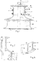
- FIG. 1 shows the exterior of a winch having a conventional internal working mechanism.
- the winch includes a main drive shaft 10 connected by internal gearing (not shown) to the drum of the winch, generally shown at 12.
- a conventional crank handle a portion of which is shown at 13, is manually cranked to rotate the drum, usually in a unidirectional clockwise direction.
- the drum 12 is rotatably mounted on a fixed support base 15 secured to the deck, with the drum being rotatable around a central vertical axis.
- the drum 12 comprises an upper substantially cylindrical portion 16 having a first diameter, the surface of which may be roughened as shown for better friction with the line 14 engaged thereon.
- the upper portion includes a top continuous and radiused lip 18 which extends radially outwardly around the drum with respect to the upper cylindrical portion 16 and a lower outwardly flaring portion or skirt 20.
- the drum 12 additionally comprises a lower line receiving cylindrical portion 22 having a second diameter greater than the diameter of the first portion 16.
- the lower portion of the skirt 20 is radiused inwardly to provide a radiused lip 24 extending around the drum radially outwardly relative to the portion 22.
- the lower portion also includes a bottom lip 26 extending radially outwardly.
- Figures 2 and 3 show another embodiment in which a conventional winch drum 30 is provided with a separate ring shaped part 32 to provide a second line receiving portion 34 of greater diameter than the diameter of the main drum.
- the standard winch drum 30 has a lower skirt 36 having a cylindrical outer surface.
- the ring-shaped part has an inner surface 38 conforming to the shape of the skirt, and an outer portion comprising a pair of spaced annular jaws or lips 40 and 42.
- the ring member 32 is secured to the lower part of the winch by means of belts 44, or by other means, such as pins or permanent adhesive.
- the control line from the spinnaker is usually led from a block attached to an aft part of the boat and back to the winch.
- the line is wrapped in a spiral one or more turns around the lower drum. Since the loads exerted on the line by the spinnaker are generally less than when in the first mode, the larger drum diameter allows for more rapid trimming per turn of the winch handle without exertion of undue effort.
- the length of the lower cylindrical portion 22 may be less than that of the upper portion 16.
- the radial extent of the central lip 24 must be sufficient to prevent the line under moderate tension from slipping upwardly from the lower drum 22 when the winch is being cranked and fresh line is being drawn onto the bottom of the drum and is being moved upwardly in a coil on the lower drum.
- the radial extent or width of the lip 24 is therefore preferably greater than the radius of the line and most preferably greater than the maximum diameter of the line to be employed on the lower drum.
- the two diameter drums of the present invention offers two separate but alternate selections of speed by winding a line on one or the other drum diameters. It is not contemplated that both modes could be used simultaneously or that one line would be wrapped around both drum diameters at the same time.
- the intermediate lip 24 prevents the line from slipping onto the upper drum when the lower drum is engaged.
- the relative diameters of the two drums may he selected to provide the desired gear ratio or speed. As one example, for a winch having a upper drum diameter of about 7.6 cm (three inches), good results are obtained by providing a lower drum diameter of about 15.2 cm (six inches), or from about 1.5 to about 3 times the diameter of the upper drum.
- the winch drum of the present invention offers a considerable advantage in that the modified drum, either in unitary or composite form, may be retrofitted to an existing conventional winch, thus providing additional speeds without the need to replace the entire winch.
Landscapes
- Engineering & Computer Science (AREA)
- Mechanical Engineering (AREA)
- Jib Cranes (AREA)
- Production Of Liquid Hydrocarbon Mixture For Refining Petroleum (AREA)
- Storage Of Web-Like Or Filamentary Materials (AREA)
- Storing, Repeated Paying-Out, And Re-Storing Of Elongated Articles (AREA)
Description
- Winches are widely employed on sailing vessels to provide a mechanical advantage while hauling in of a line. These devices, comprising a rotatable drum and an internal pawl mechanism to allow rotation of the drum in one rotary direction, are typically mounted on the deck or mast of a sailboat. Lines connected to the rigging or sails have free ends, which may be wrapped around the drum of the winch for a number of turns. Smaller winches are cranked by a crank handle inserted in the top of the winch. Larger winches may be driven from the bottom, either by a separate manual crank or by a motor. Friction between the drum and the line allows the line to he drawn in using the crank, or eased out gradually or suddenly by hand.
- Many sailboat winches have internal gearing to provide more than one speed ratio of the drum relative to the rotation of the cranking device. When the line is relatively slack, a high gear ratio may be employed, and when tension increases, a lower gear ratio may be engaged. In modern sailboat winches, gear selection is automatic upon reversal of direction of the drive input. For example, a two speed winch has a unidirectional drive permitting rotation in only the clockwise direction. When the crank handle connected to the main drive shaft of the winch in driven in the clockwise direction, the drum is driven in a first, high, gear ratio. If the crank handle is driven in the counterclockwise direction, the winch drum is driven in a clockwise direction in a lower, second gear.
- Deck mounted primary winches on sailboats are used to haul in and ease out sheets or lines attached to a foresail such as a jib or genoa when the boat is sailing at an acute angle to the wind. The same deck winch is also used to control different lines attached to a spinnaker when the boat is sailing off the wind. Since the jib sheet carries the maximum load, the power ratio of the winch, determined generally by the size and drum diameter of the winch, must accommodate this maximum load. For spinnaker work, the loads are less, and the ability to sheet in and out quickly to maintain sail shape is a primary concern on racing sailboats. For this reason, winches are sometimes equipped with additional internal gears to better accommodate the two different operating conditions, but this results in increased costs, as well as increased complexity and weight of the winch.
- GB-A-524 115 discloses a winch with two gears of different gear ratios which can be operated at two speeds. The winch is provided with a winding pulley having a circumferential wedge-shaped groove. In one embodiment the winding pulley is integrally connected to a concave drum.
- In accordance with the present invention, the drum of an otherwise conventional winch is modified to include an upper substantially cylindrical line engaging portion or drum having a first diameter relating directly to the power ratio of the winch in lowest gear. The upper cylindrical portion has a first height or length and has an outwardly projecting top lip and an outwardly flared bottom skirt, as in a conventional winch drum. This portion or drum is employed to trim sheets or lines connected to a foresail when maximum power is required.
- The internal gearing for the winch is not shown, but it is conventional and is shown in a catalog available from Harken, Inc., Pewaukee, Wisconsin, or in available patent literature.
- The winch drum also has a second lower line engaging cylindrical portion or second drum with a diameter substantially greater than the diameter of the upper portion. A continuous outwardly projecting lip is provided between the upper and lower cylindrical portions, with the radial dimension of the lip being greater than the maximum diameter of a line to be received by the winch. For spinnaker work, the line may be wrapped around the lower, larger diameter portion for hauling in and easing the line more rapidly. In effect, for example, a winch having a first and second internal gear mechanism will also have a third and fourth ratio or speed by means of the two diameters of the drum. The height or length of the second cylindrical portion may be less than that of the upper portion, since fewer turns of the line are required in this mode, or the line diameter is less than the diameter used in the first mode.
- The winch drum may be manufactured as a unitary member, or a standard or existing winch drum may be converted by securing a fabricated ring-shaped member to the lower portion of the drum.
-
- Figure 1 is a side view of a sailboat winch having a unitary drum in accordance with the present invention and showing a line, partly in cross section, engaging the upper portion of the drum.
- Figure 2 is a vertical sectional view through the drum of a conventional winch with a conversion ring-shaped part attached in accordance with the present invention.
- Figure 3 is a perspective view of a section of the ring-shaped part shown in Figure 2.
-
- Figure 1 shows the exterior of a winch having a conventional internal working mechanism. The winch includes a main drive shaft 10 connected by internal gearing (not shown) to the drum of the winch, generally shown at 12. A conventional crank handle, a portion of which is shown at 13, is manually cranked to rotate the drum, usually in a unidirectional clockwise direction. The
drum 12 is rotatably mounted on afixed support base 15 secured to the deck, with the drum being rotatable around a central vertical axis. - The
drum 12 comprises an upper substantiallycylindrical portion 16 having a first diameter, the surface of which may be roughened as shown for better friction with theline 14 engaged thereon. The upper portion includes a top continuous andradiused lip 18 which extends radially outwardly around the drum with respect to the uppercylindrical portion 16 and a lower outwardly flaring portion orskirt 20. When the winch is operated in a first mode, theline 14 is wrapped around the upper cylindrical portion. The lower section of line orjib sheet 14a leads forwardly in the boat to the sail and is the loaded portion, and the upper portion 14b is the relatively unloaded portion of the line and leads to the free end. The relatively untensioned portion 14b is trimmed or pulled by hand as the winch is being cranked. As the winch is cranked, the line is drawn in from the bottom of the drum and exits at the top. - The
drum 12 additionally comprises a lower line receivingcylindrical portion 22 having a second diameter greater than the diameter of thefirst portion 16. In the embodiment shown, the lower portion of theskirt 20 is radiused inwardly to provide aradiused lip 24 extending around the drum radially outwardly relative to theportion 22. The lower portion also includes abottom lip 26 extending radially outwardly. - Figures 2 and 3 show another embodiment in which a
conventional winch drum 30 is provided with a separate ring shapedpart 32 to provide a secondline receiving portion 34 of greater diameter than the diameter of the main drum. In this case, thestandard winch drum 30 has alower skirt 36 having a cylindrical outer surface. The ring-shaped part has aninner surface 38 conforming to the shape of the skirt, and an outer portion comprising a pair of spaced annular jaws orlips ring member 32 is secured to the lower part of the winch by means ofbelts 44, or by other means, such as pins or permanent adhesive. - For operation in the second or spinnaker mode, the control line from the spinnaker is usually led from a block attached to an aft part of the boat and back to the winch. The line is wrapped in a spiral one or more turns around the lower drum. Since the loads exerted on the line by the spinnaker are generally less than when in the first mode, the larger drum diameter allows for more rapid trimming per turn of the winch handle without exertion of undue effort.
- As shown in Figure 1, since fewer wraps of line are required on the drum when operating in the second mode the length of the lower
cylindrical portion 22 may be less than that of theupper portion 16. Also, the radial extent of thecentral lip 24 must be sufficient to prevent the line under moderate tension from slipping upwardly from thelower drum 22 when the winch is being cranked and fresh line is being drawn onto the bottom of the drum and is being moved upwardly in a coil on the lower drum. The radial extent or width of thelip 24 is therefore preferably greater than the radius of the line and most preferably greater than the maximum diameter of the line to be employed on the lower drum. - It will be understood that the two diameter drums of the present invention offers two separate but alternate selections of speed by winding a line on one or the other drum diameters. It is not contemplated that both modes could be used simultaneously or that one line would be wrapped around both drum diameters at the same time. The
intermediate lip 24 prevents the line from slipping onto the upper drum when the lower drum is engaged. - The relative diameters of the two drums may he selected to provide the desired gear ratio or speed. As one example, for a winch having a upper drum diameter of about 7.6 cm (three inches), good results are obtained by providing a lower drum diameter of about 15.2 cm (six inches), or from about 1.5 to about 3 times the diameter of the upper drum.
- The winch drum of the present invention offers a considerable advantage in that the modified drum, either in unitary or composite form, may be retrofitted to an existing conventional winch, thus providing additional speeds without the need to replace the entire winch.
Claims (7)
- A sailboat winch for hauling in a line, in which a drum is rotatably mounted on a support and means are provided for rotating the drum,
characterized in that said drum (12, 30) comprises an upper cylindrical portion (16) and a lower cylindrical portion (22), said lower cylindrical portion having a diameter greater than the upper cylindrical portion, said upper and lower cylindrical portions having a width sufficient to enable more than one turn of line to be wrapped thereon, and a continuous lip (24, 40) projecting outwardly between said upper and lower cylindrical portions to allow alternate and independent use of said portions for hauling in a line at different speed rations. - The winch of claim 1 wherein the drum (12, 30) additionally comprises an outwardly projecting annular lip (18; 26, 42) at the top and at the bottom thereof.
- The winch of claim 1 wherein the lip (24,40) has a radial extend greater than the diameter of the line.
- The winch of claim 1 wherein the upper cylindrical portion (16) is longer than the lower cylindrical portion (22).
- The winch of claim 1 wherein said drum is of unitary construction.
- The winch of claim 1 wherein said drum comprises a conventional winch drum (30) having a lower skirt (36) having a cylindrical outer surface and said lower shirt (36) comprises a separate ring-shaped member (32) secured to said lower skirt (36) the ring-shaped member (32) being provided with an outwardly projecting annular lip (40, 42) at the top and at the bottom thereof.
- The winch of claim 1 wherein said winch has a maximum power ratio corresponding to the diameter of the upper drum portion (16).
Applications Claiming Priority (2)
| Application Number | Priority Date | Filing Date | Title |
|---|---|---|---|
| US08/516,529 US5829736A (en) | 1995-08-18 | 1995-08-18 | Winch having drum of two diameters for alternative engagement by a line at two speeds |
| US516529 | 1995-08-18 |
Publications (2)
| Publication Number | Publication Date |
|---|---|
| EP0759408A1 EP0759408A1 (en) | 1997-02-26 |
| EP0759408B1 true EP0759408B1 (en) | 1999-03-17 |
Family
ID=24055989
Family Applications (1)
| Application Number | Title | Priority Date | Filing Date |
|---|---|---|---|
| EP96107172A Expired - Lifetime EP0759408B1 (en) | 1995-08-18 | 1996-05-07 | Winch with two speed ratio drum |
Country Status (6)
| Country | Link |
|---|---|
| US (1) | US5829736A (en) |
| EP (1) | EP0759408B1 (en) |
| AU (1) | AU705391B2 (en) |
| CA (1) | CA2176106A1 (en) |
| DE (1) | DE69601759T2 (en) |
| DK (1) | DK0759408T3 (en) |
Families Citing this family (13)
| Publication number | Priority date | Publication date | Assignee | Title |
|---|---|---|---|---|
| GB9713669D0 (en) * | 1997-06-27 | 1997-09-03 | Lewmar Marine Ltd | Winch |
| GB9818921D0 (en) * | 1998-08-28 | 1998-10-21 | Lewmar Marine Ltd | Winch drum |
| GB0409253D0 (en) * | 2004-04-26 | 2004-05-26 | Lewmar Ltd | Winch and winch drum |
| US7343958B1 (en) | 2005-04-04 | 2008-03-18 | Amarr Company | Overhead door lift system |
| US7494109B2 (en) * | 2006-01-25 | 2009-02-24 | Ihc Holland Ie B.V. | Winch for a segmented wire and method for operating said winch |
| MX2008013313A (en) * | 2006-04-28 | 2009-03-06 | Electronic Theatre Controls | Lift assembly, system, and method. |
| EP2217342B1 (en) | 2007-11-08 | 2014-11-05 | Electronic Theatre Controls, Inc. | Lift assembly systems and methods |
| EP2910514B1 (en) | 2009-11-18 | 2016-10-19 | Electronic Theatre Controls, Inc. | Lift assembly systems and methods |
| US8820720B2 (en) * | 2011-11-11 | 2014-09-02 | Lewmar Limited | Winch |
| US10183850B2 (en) | 2012-12-21 | 2019-01-22 | Electronic Theatre Controls, Inc. | Compact hoist system |
| CN104340910B (en) * | 2014-10-21 | 2017-04-19 | 太重(天津)滨海重型机械有限公司 | Piling ship and following cable releasing device of cable pipe of piling hammer thereof |
| CN205241011U (en) * | 2015-11-05 | 2016-05-18 | 奥的斯电梯公司 | Driving sheave, loose pulley assembly who has it and elevator |
| US11390500B2 (en) | 2019-04-26 | 2022-07-19 | Engineered Hardware, Llc | Drive drum for overhead doors |
Family Cites Families (20)
| Publication number | Priority date | Publication date | Assignee | Title |
|---|---|---|---|---|
| GB190011048A (en) * | 1900-06-18 | 1901-04-20 | Robert Grisson | Improvements relating to Hoists, Winches and the like. |
| FR387896A (en) * | 1908-03-07 | 1908-07-25 | Hillairet Huguet Soc | Stress Multiplier Deflection Doll |
| US1235504A (en) * | 1916-06-19 | 1917-07-31 | Charles S Ross | Bull or calf wheel for well-rigs. |
| US1424990A (en) * | 1920-03-29 | 1922-08-08 | Albert A Coyle | Capstan |
| US1565720A (en) * | 1924-01-17 | 1925-12-15 | Walker S Estes | Pony bull wheel |
| US1568406A (en) * | 1924-09-30 | 1926-01-05 | Shaw And Rathke | Automatic sheave |
| GB340427A (en) * | 1930-01-25 | 1931-01-01 | John Somerville Highfield | Improvements in or relating to winches and the like |
| US2435580A (en) * | 1932-09-27 | 1948-02-10 | James B Glennon | Differential drum for mine anchors |
| DE719030C (en) * | 1937-05-04 | 1942-03-27 | Otto Reiner Dipl Ing | Spill for towing vehicles of all kinds |
| GB524115A (en) * | 1939-01-23 | 1940-07-30 | Desmond Walter Molins | Improvements in or relating to winches, capstans and the like |
| US2513095A (en) * | 1947-01-20 | 1950-06-27 | Gerald R Hunt | Apparatus for handling a line in a derrick |
| US2793740A (en) * | 1954-02-23 | 1957-05-28 | Charles H Daudt | Winch |
| DE6605544U (en) * | 1967-01-31 | 1970-06-04 | Gewerk Eisenhuette Westfalia | WINCH WITH A STORAGE DRUM AND A WINCH DRUM WITH A WORKING DRUM |
| US3432146A (en) * | 1967-02-28 | 1969-03-11 | Feldmuehle Ag | Wire-drawing capstan |
| US3642253A (en) * | 1969-06-23 | 1972-02-15 | Plasmachem | Sealed silent winch |
| DK143707C (en) * | 1975-01-29 | 1982-03-22 | Lilly Co Eli | PROCEDURE FOR INSULATING GLUCAGON |
| DE2944715A1 (en) * | 1979-11-06 | 1981-05-14 | Aktien-Gesellschaft Weser, 2800 Bremen | Shipboard winch drum assembly - has dividing flange detachable from intermediate mounting for securing to one of end flanges |
| US4662609A (en) * | 1982-04-21 | 1987-05-05 | The United States Of America As Represented By The Secretary Of The Navy | Capstan adaptable "V" puller |
| NO160349C (en) * | 1984-11-23 | 1989-04-12 | Edin Ljoenes | DEVICE AT AN ANCHOR PLAY. |
| GB2215297A (en) * | 1988-03-05 | 1989-09-20 | Trent Polytechnic | Variable diameter winch drive |
-
1995
- 1995-08-18 US US08/516,529 patent/US5829736A/en not_active Expired - Lifetime
-
1996
- 1996-05-07 EP EP96107172A patent/EP0759408B1/en not_active Expired - Lifetime
- 1996-05-07 DK DK96107172T patent/DK0759408T3/en active
- 1996-05-07 DE DE69601759T patent/DE69601759T2/en not_active Expired - Fee Related
- 1996-05-08 CA CA002176106A patent/CA2176106A1/en not_active Abandoned
- 1996-05-10 AU AU52208/96A patent/AU705391B2/en not_active Ceased
Also Published As
| Publication number | Publication date |
|---|---|
| DE69601759T2 (en) | 1999-09-30 |
| US5829736A (en) | 1998-11-03 |
| DE69601759D1 (en) | 1999-04-22 |
| EP0759408A1 (en) | 1997-02-26 |
| CA2176106A1 (en) | 1997-02-19 |
| AU705391B2 (en) | 1999-05-20 |
| AU5220896A (en) | 1997-02-20 |
| DK0759408T3 (en) | 1999-10-11 |
Similar Documents
| Publication | Publication Date | Title |
|---|---|---|
| AU705391B2 (en) | Winch with two speed ratio drum | |
| US5676349A (en) | Winch wheel device with half cleat | |
| US7913979B2 (en) | Sailboat winch with self-storage of working line | |
| US4921219A (en) | Powered sailboat winch | |
| US4367688A (en) | Sailboat rig | |
| US3260230A (en) | Sail controlling means | |
| US4723499A (en) | Furling system for sailboats | |
| US20120080652A1 (en) | Line storing yacht winch with tension-applying level wind mechanism | |
| US4924795A (en) | Winch for roller reefing | |
| US6019353A (en) | Winch having a multiple diameter drum | |
| US5947451A (en) | Marine winch drum | |
| US5619946A (en) | Sail furling device with bearings to permit simultaneous cable and extrusion rotation | |
| US12492106B2 (en) | Winch arrangement for a sailing boat | |
| US5538223A (en) | Single line multiple purchase block and tackle system | |
| EP2089271A2 (en) | Sailboat control apparatus and method | |
| US4057023A (en) | Halyard rig for roll-furling mainsail | |
| EP0073358A2 (en) | Sail support and control system | |
| EP2217521B1 (en) | Ship's winch, ship provided with ship's winch | |
| US6047955A (en) | Clamp ring for a marine winch | |
| US20070137542A1 (en) | Synchronized Roller Furl System for Hoisting, Reefing and Storing of Sails | |
| US5890447A (en) | Furling device for a sailing boat | |
| EP0414707A1 (en) | Powered sailboat winch | |
| US4815709A (en) | Sailing winch and handle therefor | |
| EP1650124B1 (en) | Motion transmission system for manoeuvring the ropes of sails in sailing boats | |
| US4557213A (en) | Apparatus for furling sailboat jib |
Legal Events
| Date | Code | Title | Description |
|---|---|---|---|
| PUAI | Public reference made under article 153(3) epc to a published international application that has entered the european phase |
Free format text: ORIGINAL CODE: 0009012 |
|
| AK | Designated contracting states |
Kind code of ref document: A1 Designated state(s): DE DK FR GB IT SE |
|
| 17P | Request for examination filed |
Effective date: 19970814 |
|
| 17Q | First examination report despatched |
Effective date: 19971208 |
|
| GRAG | Despatch of communication of intention to grant |
Free format text: ORIGINAL CODE: EPIDOS AGRA |
|
| GRAG | Despatch of communication of intention to grant |
Free format text: ORIGINAL CODE: EPIDOS AGRA |
|
| GRAH | Despatch of communication of intention to grant a patent |
Free format text: ORIGINAL CODE: EPIDOS IGRA |
|
| GRAH | Despatch of communication of intention to grant a patent |
Free format text: ORIGINAL CODE: EPIDOS IGRA |
|
| GRAA | (expected) grant |
Free format text: ORIGINAL CODE: 0009210 |
|
| AK | Designated contracting states |
Kind code of ref document: B1 Designated state(s): DE DK FR GB IT SE |
|
| PLBQ | Unpublished change to opponent data |
Free format text: ORIGINAL CODE: EPIDOS OPPO |
|
| PLBI | Opposition filed |
Free format text: ORIGINAL CODE: 0009260 |
|
| REF | Corresponds to: |
Ref document number: 69601759 Country of ref document: DE Date of ref document: 19990422 |
|
| 26 | Opposition filed |
Opponent name: LEWMAR MARINE LIMITED Effective date: 19990318 |
|
| ET | Fr: translation filed | ||
| REG | Reference to a national code |
Ref country code: DK Ref legal event code: T3 |
|
| PLBF | Reply of patent proprietor to notice(s) of opposition |
Free format text: ORIGINAL CODE: EPIDOS OBSO |
|
| PGFP | Annual fee paid to national office [announced via postgrant information from national office to epo] |
Ref country code: FR Payment date: 20000419 Year of fee payment: 5 |
|
| PGFP | Annual fee paid to national office [announced via postgrant information from national office to epo] |
Ref country code: SE Payment date: 20000420 Year of fee payment: 5 Ref country code: DE Payment date: 20000420 Year of fee payment: 5 |
|
| PGFP | Annual fee paid to national office [announced via postgrant information from national office to epo] |
Ref country code: DK Payment date: 20000425 Year of fee payment: 5 |
|
| PLBF | Reply of patent proprietor to notice(s) of opposition |
Free format text: ORIGINAL CODE: EPIDOS OBSO |
|
| PG25 | Lapsed in a contracting state [announced via postgrant information from national office to epo] |
Ref country code: DK Free format text: LAPSE BECAUSE OF NON-PAYMENT OF DUE FEES Effective date: 20010507 |
|
| PG25 | Lapsed in a contracting state [announced via postgrant information from national office to epo] |
Ref country code: SE Free format text: LAPSE BECAUSE OF NON-PAYMENT OF DUE FEES Effective date: 20010508 |
|
| PLBO | Opposition rejected |
Free format text: ORIGINAL CODE: EPIDOS REJO |
|
| REG | Reference to a national code |
Ref country code: GB Ref legal event code: IF02 |
|
| APAC | Appeal dossier modified |
Free format text: ORIGINAL CODE: EPIDOS NOAPO |
|
| APAE | Appeal reference modified |
Free format text: ORIGINAL CODE: EPIDOS REFNO |
|
| PLAB | Opposition data, opponent's data or that of the opponent's representative modified |
Free format text: ORIGINAL CODE: 0009299OPPO |
|
| APAC | Appeal dossier modified |
Free format text: ORIGINAL CODE: EPIDOS NOAPO |
|
| REG | Reference to a national code |
Ref country code: DK Ref legal event code: EBP |
|
| PG25 | Lapsed in a contracting state [announced via postgrant information from national office to epo] |
Ref country code: FR Free format text: LAPSE BECAUSE OF NON-PAYMENT OF DUE FEES Effective date: 20020131 |
|
| R26 | Opposition filed (corrected) |
Opponent name: LEWMAR LIMITED Effective date: 19990318 |
|
| PG25 | Lapsed in a contracting state [announced via postgrant information from national office to epo] |
Ref country code: DE Free format text: LAPSE BECAUSE OF NON-PAYMENT OF DUE FEES Effective date: 20020301 |
|
| PLBQ | Unpublished change to opponent data |
Free format text: ORIGINAL CODE: EPIDOS OPPO |
|
| PLAB | Opposition data, opponent's data or that of the opponent's representative modified |
Free format text: ORIGINAL CODE: 0009299OPPO |
|
| R26 | Opposition filed (corrected) |
Opponent name: LEWMAR LIMITED Effective date: 19990318 |
|
| APBU | Appeal procedure closed |
Free format text: ORIGINAL CODE: EPIDOSNNOA9O |
|
| PLBN | Opposition rejected |
Free format text: ORIGINAL CODE: 0009273 |
|
| STAA | Information on the status of an ep patent application or granted ep patent |
Free format text: STATUS: OPPOSITION REJECTED |
|
| 27O | Opposition rejected |
Effective date: 20031014 |
|
| PG25 | Lapsed in a contracting state [announced via postgrant information from national office to epo] |
Ref country code: IT Free format text: LAPSE BECAUSE OF NON-PAYMENT OF DUE FEES Effective date: 20050507 |
|
| APAH | Appeal reference modified |
Free format text: ORIGINAL CODE: EPIDOSCREFNO |
|
| PGFP | Annual fee paid to national office [announced via postgrant information from national office to epo] |
Ref country code: GB Payment date: 20100528 Year of fee payment: 15 |
|
| GBPC | Gb: european patent ceased through non-payment of renewal fee |
Effective date: 20110507 |
|
| PG25 | Lapsed in a contracting state [announced via postgrant information from national office to epo] |
Ref country code: GB Free format text: LAPSE BECAUSE OF NON-PAYMENT OF DUE FEES Effective date: 20110507 |