EP0759117B2 - Device for driving a tunnel or drain pipe - Google Patents
Device for driving a tunnel or drain pipe Download PDFInfo
- Publication number
- EP0759117B2 EP0759117B2 EP95915162A EP95915162A EP0759117B2 EP 0759117 B2 EP0759117 B2 EP 0759117B2 EP 95915162 A EP95915162 A EP 95915162A EP 95915162 A EP95915162 A EP 95915162A EP 0759117 B2 EP0759117 B2 EP 0759117B2
- Authority
- EP
- European Patent Office
- Prior art keywords
- pipe
- arrangement according
- thick matter
- matter pump
- pressure
- Prior art date
- Legal status (The legal status is an assumption and is not a legal conclusion. Google has not performed a legal analysis and makes no representation as to the accuracy of the status listed.)
- Expired - Lifetime
Links
Images

Classifications
-
- E—FIXED CONSTRUCTIONS
- E21—EARTH DRILLING; MINING
- E21D—SHAFTS; TUNNELS; GALLERIES; LARGE UNDERGROUND CHAMBERS
- E21D9/00—Tunnels or galleries, with or without linings; Methods or apparatus for making thereof; Layout of tunnels or galleries
- E21D9/12—Devices for removing or hauling away excavated material or spoil; Working or loading platforms
- E21D9/124—Helical conveying means therefor
-
- E—FIXED CONSTRUCTIONS
- E21—EARTH DRILLING; MINING
- E21B—EARTH DRILLING, e.g. DEEP DRILLING; OBTAINING OIL, GAS, WATER, SOLUBLE OR MELTABLE MATERIALS OR A SLURRY OF MINERALS FROM WELLS
- E21B7/00—Special methods or apparatus for drilling
- E21B7/20—Driving or forcing casings or pipes into boreholes, e.g. sinking; Simultaneously drilling and casing boreholes
- E21B7/208—Driving or forcing casings or pipes into boreholes, e.g. sinking; Simultaneously drilling and casing boreholes using down-hole drives
-
- E—FIXED CONSTRUCTIONS
- E21—EARTH DRILLING; MINING
- E21D—SHAFTS; TUNNELS; GALLERIES; LARGE UNDERGROUND CHAMBERS
- E21D9/00—Tunnels or galleries, with or without linings; Methods or apparatus for making thereof; Layout of tunnels or galleries
- E21D9/005—Tunnels or galleries, with or without linings; Methods or apparatus for making thereof; Layout of tunnels or galleries by forcing prefabricated elements through the ground, e.g. by pushing lining from an access pit
-
- E—FIXED CONSTRUCTIONS
- E21—EARTH DRILLING; MINING
- E21D—SHAFTS; TUNNELS; GALLERIES; LARGE UNDERGROUND CHAMBERS
- E21D9/00—Tunnels or galleries, with or without linings; Methods or apparatus for making thereof; Layout of tunnels or galleries
- E21D9/12—Devices for removing or hauling away excavated material or spoil; Working or loading platforms
- E21D9/13—Devices for removing or hauling away excavated material or spoil; Working or loading platforms using hydraulic or pneumatic conveying means
Definitions
- the invention relates to an arrangement for propulsion a tunnel or sewage pipe in the preamble of claim 1 specified version.
- the Discharge via wagons and rails is easy, but quite time-consuming, because the head only then can work when the lorry is on site. With gritty-grainy Soil, but also with hard rock, will promote flushing applied.
- the flows Carrier liquid or suspension at high speed through the cutting space of the head and carries about 15% of the circulating volume with overburden.
- the carrier liquid becomes above ground via cyclones and filters etc. separated from the overburden and flows into the cycle back to.
- This method is time-consuming bulky and not suitable for all floors. at very soft, fine-grained, for example loam or clayey soils has the attitude of earth pressure proven problematic.
- the invention has for its object a Arrangement of the type specified above to improve that even on floors with soft plastic and liquid consistency Avoidance of overburden breakthrough and earth pressure the head can be kept constant.
- the solution according to the invention is based on the Thoughts out on the exit side of the with the Cutting area of the transport pipe connected to the head to build up a back pressure that also with soft plastic overburden adapted to the advance First pressure maintenance enabled.
- the outlet-side end of the transport pipe one behind the other a pressure-tight lockable stone trap and the suction side of a slurry pump can be closed in a pressure-tight manner can be connected and that the thick matter pump pressure side with a successively extendable delivery line is connected for the overburden, the thick matter pump as a hydraulically operated piston pump is designed with one or two delivery cylinders, whose delivery cylinder can be closed in a pressure-tight manner
- Material feed container opens or ends in which one connected to the delivery line, alternately connectable to the delivery cylinder or cylinders Pipe slide engages.
- the pressure-tight training the overburden transport route to the suction side of the Thick matter pump enables the given propulsion Adaptation of the counter pressure to earth pressure, and regardless of the consistency of the overburden.
- the Thick matter pump can have an additional overpressure for the removal of the overburden through the conveyor line provide.
- the thick matter pump is expedient in that against the head of the pipe mounted.
- the thick matter pump and its preferably hydraulic drive units on one Interface separable and in two neighboring Pipe pieces can be assembled.
- the transport tube of the jacking head an elastic or articulated bendable compensator to connect with the thick matter pump.
- the stone trap is rigid at the exit end of the transport pipe flanged while the compensator between the stone trap and the suction side of the Thick matter pump is arranged.
- Pressure monitoring can be carried out along the Overburden transport route at least two intervening in this Pressure sensors are arranged. Earth pressure monitoring takes place advantageously by a pressure sensor engaging in the cutting area. Two additional pressure sensors can be used immediately be placed in front of and behind the stone trap. at Exceeding a predetermined pressure drop along the stone trap can indicate the presence of a Stopfers are closed, making an interruption of tunneling for the purpose of cleaning the stone trap makes necessary.
- An advantageous embodiment of the invention stipulates that the stone trap with a pressure-tight a removable cover that can be closed on the entry side to the delivery pipe and on the outlet side to the suction side the pot connected to the thick matter pump arranged screen grid, the solid, such Stones or root pieces of a certain size, which could lead to a blockage of the delivery line, restrains.
- the stone trap can also be used as a cross slide trained, in passage opening tapering and / or containing a screen Have passage channel for the overburden channel. In case of cleaning the cross slide is moved so that the passage channel from the outside for cleaning purposes is accessible.
- a counterweight on the free side of the pipe section arranged for mass balance.
- a lubricant injection to be provided in the delivery line.
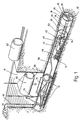
- the tunnel boring machine shown in the drawing is for the production of micro tunnels and small tunnels determines which tunnel or Wastewater pipes using the pipe compression process (pipe Jacking) from a starting shaft 10 with the help of a hydraulically actuated press slide 12 in a tunneling section 14 are introduced.
- pipe compression process pipe Jacking
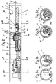
- the head 16 essentially consists from a cylindrical shield jacket 18, one of the Shield jacket delimiting on the face, motorized driven, equipped with cutting teeth 20 Scraper disc 22 and one with a motor driven Conveyor screw 24 equipped on the entry side engaging in the cutting space 26 of the head 16, through the partition 28 of the cutting space rearward reaching transport pipe 30 for the spoil 32 accumulating in the cutting space 26.
- Am exit end of the transport tube 30 is a can be closed in a pressure-tight manner by means of a cover 34 Flanged stone trap 36, the outlet port 38 via a flexible compensator 40 with the in a material feed container 42 located suction space a two-cylinder thick matter pump 44 connected is.
- the material feed container 42 is by means of a Lid 46 can be closed pressure-tight.
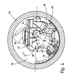
- the conveyor cylinders 48 of the thick matter pump 44 open into the front Material feed container 42. Your pistons are in the Hydraulic push-pull with the help of hydraulic cylinders 50 displaceable. Inside the material feed bin 42 is an S-shaped curved pipe switch 52, the inlet-side opening alternately in front of the Cylinder openings of the feed cylinder 48 pivoted is and its exit end 54 via a Pipe rotary connection to a delivery line leading to the outside 56 is connected.
- the control of the Thick matter pump 44 takes place via a hydraulic unit 58 and an electrical control unit 60.
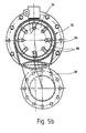
- the stone trap 36 shown in FIGS. 5a and b consists essentially of a cylindrical pot 82 with an inlet-side flange connection 84 for the transport pipe 30 and a laterally outgoing outlet outlet 38, and a screen 86, which is closed on the back by the cover 34 and is rigidly connected to it and at the end funnel-like towards the flange-side inlet opening 88 is open.
- This arrangement ensures that only such overburden that fits through the screen grid 86 to the thick matter pump 44 for removal is forwarded. With the overburden 32 arriving larger pieces collect in the sieve grid 86 and by removing the cover 34 together with the screen grid 86 from the stone trap 36 be removed.
- the starting shaft is opened 10 manufactured in the lowering process and the Press slide 12 in position within the starting shaft brought. Then the head 16 with With the help of the press slide 12 a little way into the tunneling section shifted in and the accruing Overburden removed from the starting shaft. step by step then the pipe pieces 62 in the starting shaft 10 lowered and with the press slide into the tunneling section 14 pressed.
- the thick matter pump 44 is mounted, the connected to the transport pipe 30 via the stone trap 36 becomes.
- the pressure side on the thick matter pump 44 outgoing conveyor line 56 is a two-armed Articulated tube 64 and the vertical line piece 66 led to the outside via the starting shaft 10.
- each pipe section 62 becomes a further line section 68 introduced into the starting shaft 10 and into the delivery line 56 engaged.
- the machine feed then takes place gradually over the press slide 12 one tube length each.
- sensors 70, 72, 74 the pressure in the cutting space 26 of the head 16, at the entrance to the stone trap 36 and inside the suction chamber 42 measured and monitored.
- About constipation within the thick matter pump 44 and the delivery line 56 to avoid oversized stones and roots and other contaminants that are in the ground could be intercepted with the help of the stone trap 36.
- the stone trap can be easily opened on its cover 34 for this purpose and be cleaned. This can be done automatically or done manually.
- an injection ring nozzle 76 is provided, via which a lubricant or water enters the delivery line can be injected.
- the invention relates to an arrangement for Driving along a tunnel or sewage pipe one from a starting shaft 10 to a target shaft leading heading section 14.
- the arrangement is in front especially for the production of micro tunnels or small tunnels determined where step by step pipe pieces 62 in the tunneling section against one arranged at the front Propulsion head 16 are pressed.
- To the Removal of the overburden 32 is one in the cutting area 26 of the feed head engaging screw conveyor provided at the outlet end a stone trap that can be closed in a pressure-tight manner 36 and the pressure side closable suction side 42 a thick matter pump 44 can be connected while the thick matter pump 44 on the pressure side with a successive extensible conveyor line 56 connected for the overburden is.
Description
Die Erfindung betrifft eine Anordnung zum Vortrieb eines Tunnel- oder Abwasserrohrs des im Oberbegriff des Anspruchs 1 angegebenen Fassung.The invention relates to an arrangement for propulsion a tunnel or sewage pipe in the preamble of claim 1 specified version.
Anordnungen der vorstehenden Art, die nach
dem Rohrpressungsverfahren (Pipe Jacking) arbeiten,
Sind bekannt (DE 34 03 890 C1). Sie werden häufig zur Herstellung von Mikrotunneln und
Kleintunneln bis etwa 3 m Durchmesser und Längen bis
ca. 800 m verwendet. Dabei wird ein getriebener Vortriebskopf
durch den Preßschlitten bei ständiger Ergänzung
von zusätzlichen Rohrstücken durch das Erdreich
gedrückt. Der anfallende Abraum wird bisher entweder
über Förderbänder, Loren oder durch Ausspülen (Spülförderung)
nach außen gefördert. Dabei ist der Bandaustrag
relativ aufwendig, wenn man berücksichtigt,
daß die Bänder beim Nachschieben der Rohrstücke
ständig verlängert werden müssen. Hinzu kommt der
relativ große Platzbedarf einer Bandförderanlage. Der
Austrag über Loren und Schienen ist zwar einfach, aber
recht zeitaufwendig, da der Vortriebskopf nur dann
arbeiten kann, wenn die Lore vor Ort ist. Bei kiesig-körnigem
Boden, aber auch bei hartem Gestein, wird Spülförderung
angewendet. Dabei fließt die
Trägerflüssigkeit oder Suspension mit hoher Geschwindigkeit
durch den Schneidraum des Vortriebskopfs und
reißt etwa 15% des Umlaufvolumens an Abraum mit.
Überirdisch wird die Trägerflüssigkeit über Zyklone, Filter
usw. vom Abraum getrennt und fließt dem Kreislauf
wieder zu. Diese Methode ist aufwendig, übertägig
platzraubend und nicht für alle Böden geeignet. Bei
sehr weichen, feinkörnigen, beispielsweise lehm- oder
tonhaltigen Böden hat sich die Haltung des Erddruckes
als problematisch erwiesen. Es werden deshalb sogenannte
Erddruckschilde verwendet, bei denen es darauf
ankommt, daß sich der Vorschub und der Abtransport
des abgeförderten Materials exakt die Waage halten, so
daß weder eine Hebung des Bodens noch eine Bodensetzung
auftreten kann. Diese Bedingung kann jedoch
nur dann eingehalten werden, wenn der Abraum gegenüber
der Austragschnecke noch so viel Reibung aufweist,
daß der Erddruck gehalten werden kann. Dies gilt
zwar für steifplastische und plastische Böden, nicht
jedoch für Böden mit weichplastischer oder flüssiger
Konsistenz, die über die Austragschnecke nicht genügend
Reibung aufbauen können.Arrangements of the above kind, according to
the pipe pressing process (pipe jacking),
Are known (
Bei einem Vortriebskopf einer Tunnelvortriebsmaschine, der ein mit einer Förderschnecke bestücktes Transportrohr für den Abtransport des Abraums aufweist, ist es an sich bekannt (DE-A 3330635), an das austrittseitige Ende des Transportrohrs eine Siebeinrichtung anzuschließen, der eine Materialschleuse nachgeschaltet ist. Aus der Siebeinrichtung fallen Wasser- und Feinmaterial in einen darunter liegenden Sammelbehälter, der über einen Ausgang entleerbar ist.With a tunnel head of a tunnel boring machine, the one equipped with a screw conveyor Has transport tube for the removal of the overburden, it is known per se (DE-A 3330635) to which a screening device at the outlet end of the transport pipe to join the a material lock is connected downstream. Water falls out of the sieve and fine material in an underlying container, which can be emptied via an outlet.
Der Erfindung liegt die Aufgabe zugrunde, eine Anordnung der eingangs angegebenen Art dahingehend zu verbessern, daß auch bei Böden mit weichplastischer und flüssiger Konsistenz ein Abraumdurchbruch vermieden und der Erddruck vor den Vortriebskopf konstant gehalten werden kann.The invention has for its object a Arrangement of the type specified above to improve that even on floors with soft plastic and liquid consistency Avoidance of overburden breakthrough and earth pressure the head can be kept constant.
Zur Lösung dieser Aufgabe wird die im Patentanspruch 1 angegebene Merkmalskombination vorgeschlagen. Vorteilhafte Ausgestaltungen und Weiterbildungen der Erfindung ergeben sich aus den abhängigen Ansprüchen.To solve this problem is the claim 1 specified combination of features proposed. Advantageous configurations and Further developments of the invention result from the dependent claims.
Die erfindungsgemäße Lösung geht von dem Gedanken aus, auf der Austrittsseite des mit dem Schneidraum des Vortriebskopfes verbundenen Transportrohrs einen Gegendruck aufzubauen, der auch bei weichplastischem Abraum eine dem Vortrieb angepaßte Erstdruckhaltung ermöglicht. Um dies zu erreichen, wird gemäß der Erfindung vorgeschlagen, daß an das austrittsseitige Ende des Transportrohrs hintereinander eine druckdicht verschließbare Steinfalle und die druckdicht verschließbare Saugseite einer Dickstoffpumpe anschließbar sind und daß die Dickstoffpumpe druckseitig mit einer sukzessive verlängerbaren Förderleitung für den Abraum verbunden ist, wobei die Dickstoffpumpe als hydraulisch betätigbare Kolbenpumpe mit einem oder zwei Förderzylindern ausgebildet ist, deren Förderzylinder in einen druckdicht verschließbaren Materialaufgabebehälter mündet bzw. münden, in welchen ein an die Förderleitung angeschlossener, abwechselnd an den oder die Förderzylinder anschließbarer Rohrschieber eingreift. Die druckdichte Ausbildung der Abraumtransportstrecke bis zur Saugseite der Dickstoffpumpe ermöglicht bei gegebenem Vortrieb die Anpassung des Gegendrucks an den Erddruck, und zwar unabhängig von der Konsistenz des Abraums. Die Dickstoffpumpe kann einen zusätzlichen Überdruck zum Abtransport des Abraums durch die Förderleitung zur Verfügung stellen. Die erfindungsgemäße Steinfalle vor der Saugseite der Dickstoffpumpe, die gleichfalls hermetisch abgeschlossen ist, sorgt dafür, daß es entlang der Förderleitung zu keinen Stopfern, die nur schwer auffindbar wären, kommen kann.The solution according to the invention is based on the Thoughts out on the exit side of the with the Cutting area of the transport pipe connected to the head to build up a back pressure that also with soft plastic overburden adapted to the advance First pressure maintenance enabled. To achieve this, It is proposed according to the invention that the outlet-side end of the transport pipe one behind the other a pressure-tight lockable stone trap and the suction side of a slurry pump can be closed in a pressure-tight manner can be connected and that the thick matter pump pressure side with a successively extendable delivery line is connected for the overburden, the thick matter pump as a hydraulically operated piston pump is designed with one or two delivery cylinders, whose delivery cylinder can be closed in a pressure-tight manner Material feed container opens or ends in which one connected to the delivery line, alternately connectable to the delivery cylinder or cylinders Pipe slide engages. The pressure-tight training the overburden transport route to the suction side of the Thick matter pump enables the given propulsion Adaptation of the counter pressure to earth pressure, and regardless of the consistency of the overburden. The Thick matter pump can have an additional overpressure for the removal of the overburden through the conveyor line provide. The stone trap according to the invention in front of the suction side of the thick matter pump, which also Hermetically sealed, it ensures that it is along the delivery line to no blockers that only would be difficult to find.
Die Dickstoffpumpe wird zweckmäßig in das gegen den Vortriebskopf anliegenden Rohrstück montiert. Dabei können die Dickstoffpumpe und ihre vorzugsweise hydraulischen Antriebsaggregate an einer Schnittstelle auftrennbar und in zwei benachbarten Rohrstücken montierbar sein. Um mit dem Vortriebskopf auch Kurven durchfahren zu können, ist es zweckmäßig, das Transportrohr des Vortriebskopfes mit einem elastisch oder gelenkig verbiegbaren Kompensator mit der Dickstoffpumpe zu verbinden. Zweckmäßig ist dabei die Steinfalle starr an das austrittsseitige Ende des Transportrohrs angeflanscht, während der Kompensator zwischen der Steinfalle und der Saugseite der Dickstoffpumpe angeordnet ist.The thick matter pump is expedient in that against the head of the pipe mounted. The thick matter pump and its preferably hydraulic drive units on one Interface separable and in two neighboring Pipe pieces can be assembled. To with the jacking head to be able to drive through curves, it is advisable the transport tube of the jacking head an elastic or articulated bendable compensator to connect with the thick matter pump. expedient the stone trap is rigid at the exit end of the transport pipe flanged while the compensator between the stone trap and the suction side of the Thick matter pump is arranged.
Zur Drucküberwachung können entlang der Abraumtransportstrecke mindestens zwei in diese eingreifende Drucksensoren angeordnet werden. Die Erddrucküberwachung erfolgt dabei vorteilhafterweise durch einen in den Schneidraum eingreifenden Drucksensor. Zwei weitere Drucksensoren können unmittelbar vor und hinter der Steinfalle angeordnet werden. Bei Überschreiten eines vorgegebenen Druckabfalls entlang der Steinfalle kann auf das Vorhandensein eines Stopfers geschlossen werden, der eine Unterbrechung des Vortriebs zum Zwecke der Reinigung der Steinfalle erforderlich macht.Pressure monitoring can be carried out along the Overburden transport route at least two intervening in this Pressure sensors are arranged. Earth pressure monitoring takes place advantageously by a pressure sensor engaging in the cutting area. Two additional pressure sensors can be used immediately be placed in front of and behind the stone trap. at Exceeding a predetermined pressure drop along the stone trap can indicate the presence of a Stopfers are closed, making an interruption of tunneling for the purpose of cleaning the stone trap makes necessary.
Eine vorteilhafte Ausgestaltung der Erfindung sieht vor, daß die Steinfalle ein in einem druckdicht mit einem abnehmbaren Deckel verschließbaren, eintrittsseitig an das Förderrohr und austrittsseitig an die Saugseite der Dickstoffpumpe angeschlossenen Topf angeordnetes Siebgitter aufweist, das Festkörper, wie Steine oder Wurzelstücke über einer gewissen Größe, die zu einer Verstopfung der Förderleitung führen könnten, zurückhält. Zur Reinigung des Siebgitters ist bei angehaltenem Vortrieb der Deckel abzunehmen. Alternativ dazu kann die Steinfalle auch einen als Querschieber ausgebildeten, sich in Durchtrittsöffnung verjüngenden und/oder ein Siebgitter enthaltenden Durchlaßkanal für den Abraumkanal aufweisen. Im Reinigungsfall wird der Querschieber so verschoben, daß der Durchlaßkanal von außen her zu Reinigungszwekken zugänglich ist.An advantageous embodiment of the invention stipulates that the stone trap with a pressure-tight a removable cover that can be closed on the entry side to the delivery pipe and on the outlet side to the suction side the pot connected to the thick matter pump arranged screen grid, the solid, such Stones or root pieces of a certain size, which could lead to a blockage of the delivery line, restrains. To clean the sieve grid is at stopped driving the covers. alternative the stone trap can also be used as a cross slide trained, in passage opening tapering and / or containing a screen Have passage channel for the overburden channel. In case of cleaning the cross slide is moved so that the passage channel from the outside for cleaning purposes is accessible.
Um für Wartungszwecke einen Freiraum zwischen Dickstoffpumpe und Rohrwand freizuhalten, wird vor allem bei Tunnelrohren mit kleinem Durchmesser die Dickstoffpumpe und/ oder ihre Antriebsaggregate einseitig zur vertikalen Symmetrieebene der Tunnelrohre versetzt angeordnet. Um ein Verrollen des Vortriebskopfes um die Längsachse zu vermeiden, wird gemäß einer vorteilhaften Ausgestaltung der Erfindung auf der Freiraumseite des Rohrstücks ein Kontergewicht für den Massenausgleich angeordnet.To leave a space between for maintenance purposes Keeping the slurry pump and pipe wall clear especially with small diameter tunnel tubes the thick matter pump and / or its drive units one-sided to the vertical plane of symmetry of the tunnel tubes staggered. To prevent the head from rolling to avoid the longitudinal axis according to an advantageous embodiment of the invention a counterweight on the free side of the pipe section arranged for mass balance.
Da bei schwankender Abraumkonsistenz auch die Reibung in der Förderleitung variiert und teilweise sehr hoch sein kann, ist es vorteilhaft, in der Nähe des Druckausgangs der Dickstoffpumpe eine Gleitmittelinjektion in die Förderleitung vorzusehen. Dort kann ein spezielles Gleitmittel, oder auch nur Wasser, kontinuierlich in die Förderleitung injiziert und ein Gleitfilm zwischen Fördermaterial und Rohrinnenwand aufgebaut werden.Because with fluctuating overburden consistency too the friction in the delivery line varies and partly can be very high, it is advantageous to be close to the Pressure output of the thick matter pump a lubricant injection to be provided in the delivery line. There can be a special lubricant, or just water, continuously injected into the delivery line and a sliding film between Conveyed material and inner pipe wall built become.
Im folgenden wird die Erfindung anhand eines in der Zeichnung in schematischer Weise dargestellten Ausführungsbeispiels näher erläutert. Es zeigen:
- Fig. 1
- eine nach dem Rohrpreßverfahren arbeitende Tunnelvortriebsmaschine in schaubildlicher Darstellung;
- Fig. 2
- eine Seitenansicht der Vortriebsmaschine nach Fig. 1;
- Fig. 3a bis d
- Schnitte entlang den Schnittlinien A-A, B-B, C-C und D-D der Fig. 2;
- Fig. 4
- eine vergrößerte Darstellung der Fig. 3d,
- Fig. 5a und b
- einen Längsschnitt durch die Steinfalle nach Fig. 2 und einen Schnitt entlang der Schnittlinie 5-5 der Fig. 5a.
- Fig. 1
- a tunnel boring machine working according to the pipe pressing method in a diagram;
- Fig. 2
- a side view of the tunneling machine of FIG. 1;
- 3a to d
- Sections along the section lines AA, BB, CC and DD of Fig. 2;
- Fig. 4
- 3 shows an enlarged illustration of FIG. 3d,
- 5a and b
- a longitudinal section through the stone trap of FIG. 2 and a section along the section line 5-5 of FIG. 5a.
Die in der Zeichnung dargestellte Tunnelvortriebsmaschine
ist für die Herstellung von Mikrotunneln
und Kleintunneln bestimmt, bei welchen Tunnel- oder
Abwasserrohre im Rohrpressungsverfahren (Pipe
Jacking) von einem Startschacht 10 aus mit Hilfe eines
hydraulisch betätigbaren Preßschlittens 12 in eine Vortriebsstrecke
14 eingebracht werden.The tunnel boring machine shown in the drawing
is for the production of micro tunnels
and small tunnels determines which tunnel or
Wastewater pipes using the pipe compression process (pipe
Jacking) from a starting
Der Vortriebskopf 16 besteht im wesentlichen
aus einem zylindrischen Schildmantel 18, einer den
Schildmantel stirnseitig begrenzenden, motorisch
angetriebenen, mit Schneidzähnen 20 bestückten
Schürfscheibe 22 und einem mit einer motorisch angetriebenen
Förderschnecke 24 bestückten, eintrittsseitig
in den Schneidraum 26 des Vortriebskopfs 16 eingreifenden,
durch die Trennwand 28 des Schneidraums
nach hinten hindurchgreifenden Transportrohr 30 für
den im Schneidraum 26 anfallenden Abraum 32. Am
austrittsseitigen Ende des Transportrohrs 30 ist eine
mittels eines Deckels 34 druckdicht verschließbare
Steinfalle 36 angeflanscht, deren Auslaßstutzen 38
über einen biegsamen Kompensator 40 mit dem in
einem Materialaufgabebehälter 42 befindlichen Saugraum
einer Zweizylinder-Dickstoffpumpe 44 verbunden
ist. Der Materialaufgabebehälter 42 ist mit Hilfe eines
Deckels 46 druckdicht verschließbar. Die Förderzylinder
48 der Dickstoffpumpe 44 münden stirnseitig in den
Materialaufgabebehälter 42. Ihre Kolben sind im
Gegentakt hydraulisch mit Hilfe der Hydrozylinder 50
verschiebbar. Innerhalb des Materialaufgabebehälters
42 befindet sich eine S-förmig gebogene Rohrweiche
52, deren eintrittsseitige Öffnung abwechselnd vor die
Zylinderöffnungen der Förderzylinder 48 geschwenkt
wird und deren austrittsseitiges Ende 54 über eine
Rohrdrehverbindung an eine nach außen führende Förderleitung
56 angeschlossen ist. Die Ansteuerung der
Dickstoffpumpe 44 erfolgt über ein Hydraulikaggregat
58 und eine elektrische Steuereinheit 60.The
Die in Fig. 5a und b gezeigte Steinfalle 36
besteht im wesentlichen aus einem zylindrischen Topf
82 mit einem eintrittsseitigen Flanschanschluß 84 für
das Transportrohr 30 und einem seitlich abgehenden
ausgangsseitigen Auslaßstutzen 38, sowie einem Siebgitter
86, das rückseitig durch den Deckel 34 verschlossen
und mit diesem starr verbunden ist und stirnseitig
trichterartig zur flanschseitigen Eintrittsöffnung 88 hin
offen ist. Mit dieser Anordnung wird sichergestellt, daß
nur solcher Abraum, der durch das Siebgitter 86 hindurchpaßt,
an die Dickstoffpumpe 44 für den Abtransport
weitergeleitet wird. Mit dem Abraum 32
ankommende größere Stücke sammeln sich im Siebgitter
86 und können durch Abnahme des Deckelsl 34
zusammen mit dem Siebgitter 86 aus der Steinfalle 36
entfernt werden.The
Zu Beginn der Tunnelarbeiten wird der Startschacht
10 im Absenkverfahren hergestellt und der
Preßschlitten 12 innerhalb des Startschachtes in Position
gebracht. Sodann wird der Vortriebskopf 16 mit
Hilfe des Preßschlittens 12 ein Stück weit in die Vortriebsstrecke
hinein verschoben und der anfallende
Abraum aus dem Startschacht entfernt. Zug um Zug
werden dann die Rohrstücke 62 im Startschacht 10
abgesenkt und mit dem Preßschlitten in die Vortriebsstrecke
14 gepreßt. Im ersten Rohrstück 62 hinter dem
Vortriebskopf 16 ist die Dickstoffpumpe 44 montiert, die
über die Steinfalle 36 an das Transportrohr 30 angeschlossen
wird. Die druckseitig an der Dickstoffpumpe
44 abgehende Förderleitung 56 wird über ein zweiarmiges
Gelenkrohr 64 und das vertikale Leitungsstück 66
über den Startschacht 10 nach außen geführt. Mit
jedem Rohrstück 62 wird ein weiterer Leitungsabschnitt
68 in den Startschacht 10 eingeführt und in die Förderleitung
56 eingekuppelt. Der Vorschub der Maschine
erfolgt dann über den Preßschlitten 12 schrittweise um
jeweils eine Rohrstücklänge. Während des Vortriebs
wird durch geeignet positionierte Sensoren 70, 72, 74
der Druck im Schneidraum 26 des Vortriebskopfs 16,
am Eingang der Steinfalle 36 und innerhalb des Saugraums
42 gemessen und überwacht. Um Verstopfungen
innerhalb der Dickstoffpumpe 44 und der Förderleitung
56 zu vermeiden, werden übergroße Steine und Wurzeln
und sonstige Verunreinigungen, die im Boden sein
könnten, mit Hilfe der Steinfalle 36 abgefangen. Durch
kontinuierliche Messung des Erddruckes über die
Drucksensoren 72, 74 vor und hinter der Steinfalle 36 ist
sichergestellt, daß ein Stopfer sofort entdeckt und
anschließend beseitigt werden kann. Die Steinfalle
kann zu diesem Zweck an ihrem Deckel 34 leicht geöffnet
und gereinigt werden. Dies kann entweder automatisch
oder manuell erfolgen.At the start of the tunnel work, the starting shaft is opened
10 manufactured in the lowering process and the
Da bei schwankender Bodenkonsistenz auch
der Reibwiderstand in der Förderleitung 56 schwanken
und teilweise sehr hoch sein kann, ist am Eingang der
Förderleitung 56 eine Injektionsringdüse 76 vorgesehen,
über die ein Gleitmittel oder Wasser in die Förderleitung
injiziert werden kann.Because with fluctuating soil consistency too
the frictional resistance in the
Da sowohl die Dickstoffpumpe 44 als auch das
Hydraulikaggregat 58 für Reparaturzwecke zugänglich
sein müssen, sind sie unter Freilassung eines Freiraums
78 einseitig zur Tunnelhochachse angeordnet.
Durch zusätzlich im betreffenden Rohrstück 62 angebrachte
Kontergewichte 80 wird ein Massenausgleich
bewirkt, um ein Verrollen des Vortriebskopfs 16 zu verhindern.Since both the
Zusammenfassend ist folgendes festzustellen:
Die Erfindung bezieht sich auf eine Anordnung zum
Vortrieb eines Tunnel- oder Abwasserrohrs entlang
einer von einem Startschacht 10 zu einem Zielschacht
führenden Vortriebsstrecke 14. Die Anordnung ist vor
allem für die Herstellung von Mikrotunneln oder Kleintunneln
bestimmt, bei denen Zug um Zug Rohrstücke
62 in die Vortriebsstrecke gegen einen stirnseitig angeordneten
Vortriebskopf 16 gepreßt werden. Zum
Abtransport des Abraums 32 ist eine in den Schneidraum
26 des Vortriebskopfs eingreifende Förderschnecke
vorgesehen, an deren austrittsseitiges Ende
hintereinander eine druckdicht verschließbare Steinfalle
36 und die druckdicht verschließbare Saugseite 42
einer Dickstoffpumpe 44 anschließbar sind, während
die Dickstoffpume 44 druckseitig mit einer sukzessive
verlängerbaren Förderleitung 56 für den Abraum verbunden
ist.In summary, the following can be stated:
The invention relates to an arrangement for
Driving along a tunnel or sewage pipe
one from a starting
Claims (14)
- An arrangement for driving a tunnel or drain pipe along a driving stretch (14) leading from a starting shaft (10) to a target shaft, comprising a driving head (16), which has a cylindrical shell (18) and a drilling disk (22), which can be rotated on the front side about a center axis of the shell and can be driven by a motor, a number of pipe pieces (62), which can be introduced one after the other through the starting shaft (10) into the driving stretch (14), a first pipe piece (62) of the pipe pieces rests axially against the shell (18) of the driving head (16), a pressing carriage (12), which can be supported on an abutment within the starting shaft (10), and presses the pipe pieces (62) axially in the direction of the driving stretch (14), a cutting chamber (26), which can be loaded with ground spoil (32) through openings in the drilling disk, a transporting pipe (30) for the removal of the spoil (32) out of the cutting chamber (26), which transporting pipe is preferably equipped with a conveyor worm (24) or a pair of conveyor-worms, a spoil transporting stretch having means on its outlet side to be connected to the transporting pipe, and a thick matter pump (44) having a vacuum side which can be closed off pressure-tight, wherein the thick matter pump (44) is connected on its pressure side to a successively extendable conveyor line (56, 68, 66) for the spoil (32), the thick matter pump (44) being designed as a hydraulically operable piston pump with one or two conveyor cylinders (48), characterized in that the spoil transporting stretch comprises a stone trap (36), which can be closed off pressure-tight, in that the stone trap (36) and the vacuum side (42) of the thick matter pump (44) can be connected one after the other to the outlet end of the transporting pipe (30), and in that the conveyor cylinder or cylinders (48) end or ends in a material-feed container, which can be closed off pressure-tight, and into which extends a pipe switch (52) connected to the conveyor line (56) and alternately connectable to one conveyor cylinder or the conveyor cylinders (48).
- The arrangement according to Claim 1, characterized in that the thick matter pump (44) is mounted into the first pipe piece (62) resting against the driving head (16)
- The arrangement according to Claims 1 or 2, characterized in that the thick matter pump (44) and its preferably hydraulic driving aggregates (58) are separatable at a cutting point and is mounted into two adjacent pipe pieces (62).
- The arrangement according to one of the Claims 1 to 3, characterized by at least two pressure sensors (72, 74) arranged along the spoil transporting stretch and extending into said stretch.
- The arrangement according to Claim 4, characterized in that one pressure sensor (72, 74) is arranged directly in front of or behind the stone trap (36).
- The arrangement according to one of the Claims 1 to 5, characterized by a pressure sensor (70) extending into the cutting chamber (26).
- The arrangement according to one of the Claims 1 to 6, characterized by at least one pressure sensor extending into the conveyor line (56).
- The arrangement according to one of the Claims 1 to 7, characterized in that the stone trap (36) has a screen grid arranged in a pot, which can be closed off pressure-tight with a removable lid (34), and is connected on the inlet side to the transporting pipe (30) and on the outlet side to the vacuum side (42) of the thick matter pump (44).
- The arrangement according to one of the Claims 1 to 7, characterized in that the stone trap (36) has a passage channel for the spoil (32), which passage channel is designed as a cross slide, tapers in passage direction and/or contains a screen grid.
- The arrangement according to one of the Claims 1 to 9, characterized in that the thick matter pump (44) and/or its driving aggregates (58) are mounted laterally offset, leaving an open space (78) with respect to the vertical axis of the respective pipe piece (62), and that a counterweight (80) is arranged on the open-space side of the pipe piece (62).
- The arrangement according to one of the Claims 1 to 10, characterized in that the transporting pipe (30) of the driving head is connected to the thick matter pump (44) by means of an elastically or hingedly flexible compensator (40).
- The arrangement according to one of the Claims 1 to 11, characterized in that between the stone trap (36) and the vacuum side (42) of the thick matter pump (44) there is arranged an elastically flexible compensator (40).
- The arrangement according to one of the Claims 1 to 12, characterized in that a lubricant injector (76), preferably designed as a slide ring nozzle, is arranged in the conveyor line (56).
- The arrangement according to one of the Claims 1 to 13, characterized in that the pressing carriage (12) carries an articulated pipe (64) connectable to the conveyor line (56).
Applications Claiming Priority (3)
| Application Number | Priority Date | Filing Date | Title |
|---|---|---|---|
| DE4415399 | 1994-05-03 | ||
| DE4415399A DE4415399C2 (en) | 1994-05-03 | 1994-05-03 | Arrangement for driving a tunnel or sewage pipe |
| PCT/EP1995/001137 WO1995030065A1 (en) | 1994-05-03 | 1995-03-25 | Device for driving a tunnel or drain pipe |
Publications (3)
| Publication Number | Publication Date |
|---|---|
| EP0759117A1 EP0759117A1 (en) | 1997-02-26 |
| EP0759117B1 EP0759117B1 (en) | 2000-01-26 |
| EP0759117B2 true EP0759117B2 (en) | 2004-09-08 |
Family
ID=6517058
Family Applications (1)
| Application Number | Title | Priority Date | Filing Date |
|---|---|---|---|
| EP95915162A Expired - Lifetime EP0759117B2 (en) | 1994-05-03 | 1995-03-25 | Device for driving a tunnel or drain pipe |
Country Status (4)
| Country | Link |
|---|---|
| US (1) | US5749678A (en) |
| EP (1) | EP0759117B2 (en) |
| DE (2) | DE4415399C2 (en) |
| WO (1) | WO1995030065A1 (en) |
Families Citing this family (17)
| Publication number | Priority date | Publication date | Assignee | Title |
|---|---|---|---|---|
| WO1997007295A1 (en) * | 1995-08-17 | 1997-02-27 | Roland Beck | Building underpinning process |
| FR2753254B1 (en) * | 1996-09-09 | 1998-10-16 | Gaz De France | CONDUIT CONNECTION METHOD |
| DE102007002399B4 (en) * | 2007-01-10 | 2012-06-21 | Bhg Brechtel Gmbh | Method and device for producing a cased continuous bore |
| DE202008004873U1 (en) | 2008-04-08 | 2008-07-10 | Voith Patent Gmbh | applicator roll |
| US9039330B1 (en) | 2010-06-01 | 2015-05-26 | LLAJ, Inc. | Pipe boring shield |
| IT1404615B1 (en) * | 2011-02-21 | 2013-11-29 | Elas Geotecnica Srl | PROCEDURE AND EQUIPMENT FOR THE CONSTRUCTION OF TUNNELS |
| CN102226400B (en) * | 2011-05-31 | 2012-09-12 | 中铁隧道装备制造有限公司 | Method and system for preventing clamping stagnation of shield body due to too large frictional resistance in earth pressure balance shield machine |
| JP6295454B2 (en) * | 2013-11-20 | 2018-03-20 | 株式会社ココム | Permeable pipes and composite permeated pipes and their construction methods by the propulsion method |
| CN103899320B (en) * | 2014-03-26 | 2016-02-03 | 中铁工程装备集团有限公司 | Direct pipelayer |
| DK3106608T3 (en) | 2015-06-19 | 2021-04-26 | Entreprenoerfirmaet Oestergaard Vejle As | Tunnel excavator and method of excavating a tunnel |
| CN106759593A (en) * | 2017-01-18 | 2017-05-31 | 王燏斌 | A kind of groover and its construction method for hypogee |
| CN107503759A (en) * | 2017-01-18 | 2017-12-22 | 王燏斌 | A kind of mole and its construction method for push bench process |
| CN107420056B (en) * | 2017-09-29 | 2023-06-23 | 兰州理工大学 | Special dust keeper of rock soil property site consolidates rig |
| JP7012600B2 (en) * | 2018-05-11 | 2022-01-28 | 鹿島建設株式会社 | Pumping method |
| CN110005424A (en) * | 2019-04-22 | 2019-07-12 | 中建三局基础设施建设投资有限公司 | It is a kind of for weakening the device and its application method that shield screw machine is gushed |
| CN113931633A (en) * | 2021-09-28 | 2022-01-14 | 陕西能源凉水井矿业有限责任公司 | EBZ-160 heading machine water system |
| CN117108824B (en) * | 2023-10-24 | 2024-03-08 | 中隧方盾(天津)市政工程有限公司 | High-precision distance control device applied to pipe jacking construction |
Citations (6)
| Publication number | Priority date | Publication date | Assignee | Title |
|---|---|---|---|---|
| US3915347A (en) † | 1972-10-13 | 1975-10-28 | Nat Res Dev | Double gate valve for passing material from a pressurized side of a bulkhead |
| US4116011A (en) † | 1976-06-04 | 1978-09-26 | Pablo Girault | Method of excavating tunnels |
| DE3537780A1 (en) † | 1985-07-26 | 1987-01-29 | Schweitzer Karl Friedrich | Apparatus for constructing galleries or tunnels by shield driving |
| DE2927324C2 (en) † | 1979-07-06 | 1988-08-25 | Friedrich Wilh. Schwing Gmbh, 4690 Herne, De | Cleaning device for concrete pump - has chamber containing cleaning ball, moved from external disengaged position into injection position |
| US4886396A (en) † | 1988-05-12 | 1989-12-12 | Kabushiki Kaisha Iseki Kaihatsu Koki | Existing pipeline renewing method and apparatus therefor |
| DE4202060A1 (en) † | 1992-01-25 | 1993-07-29 | Westfalia Becorit Ind Tech | Device for sealing working chamber of shield drive device on delivery unit for heaping spoil - involves tight suspension introduced from outside into delivery pipe conduit which produces sealing plug |
Family Cites Families (12)
| Publication number | Priority date | Publication date | Assignee | Title |
|---|---|---|---|---|
| US4576515A (en) * | 1982-09-20 | 1986-03-18 | Nippon Telegraph & Telephone Public Corp. | Pipe laying apparatus |
| DE3330635A1 (en) * | 1983-08-25 | 1985-03-21 | Wayss & Freytag Ag, 6000 Frankfurt | Driving shield |
| DE3403890C1 (en) * | 1984-02-04 | 1985-03-14 | Hochtief Ag Vorm. Gebr. Helfmann, 4300 Essen | Conveyor device for a tunneling machine for tunnels and lines |
| JPS62107199A (en) * | 1985-11-01 | 1987-05-18 | 株式会社小松製作所 | Soil and sand carry-out device for shield excavator |
| DE3537593C1 (en) * | 1985-10-16 | 1986-09-11 | Wayss & Freytag Ag, 6000 Frankfurt | Driving shield |
| CN1008827B (en) * | 1987-05-01 | 1990-07-18 | 霍蒂夫股份公司霍夫曼兄弟公司 | Earthguard cover |
| US4818026A (en) * | 1987-12-29 | 1989-04-04 | Kabushiki Kaisha Komatsu Seisakusho | Shield type tunneling apparatus |
| US4915543A (en) * | 1988-05-12 | 1990-04-10 | Kabushiki Kaisha Iseki Kaihatsu Koki | Existing pipeline renewing method and apparatus therefor |
| JPH06100075B2 (en) * | 1988-05-16 | 1994-12-12 | 株式会社橋本設備工業所 | Exhaust method for excavated soil in the propulsion method |
| JP2519105B2 (en) * | 1989-07-28 | 1996-07-31 | 株式会社イセキ開発工機 | Shield tunnel excavator |
| US5203614A (en) * | 1991-06-17 | 1993-04-20 | The Robbins Company | Tunneling machine having liquid balance low flow slurry system |
| DE4315196A1 (en) * | 1993-05-07 | 1994-11-10 | Lars Dipl Ing Babendererde | Tunnelling machine |
-
1994
- 1994-05-03 DE DE4415399A patent/DE4415399C2/en not_active Expired - Fee Related
-
1995
- 1995-03-25 US US08/732,395 patent/US5749678A/en not_active Expired - Fee Related
- 1995-03-25 DE DE59507702T patent/DE59507702D1/en not_active Expired - Fee Related
- 1995-03-25 WO PCT/EP1995/001137 patent/WO1995030065A1/en active IP Right Grant
- 1995-03-25 EP EP95915162A patent/EP0759117B2/en not_active Expired - Lifetime
Patent Citations (6)
| Publication number | Priority date | Publication date | Assignee | Title |
|---|---|---|---|---|
| US3915347A (en) † | 1972-10-13 | 1975-10-28 | Nat Res Dev | Double gate valve for passing material from a pressurized side of a bulkhead |
| US4116011A (en) † | 1976-06-04 | 1978-09-26 | Pablo Girault | Method of excavating tunnels |
| DE2927324C2 (en) † | 1979-07-06 | 1988-08-25 | Friedrich Wilh. Schwing Gmbh, 4690 Herne, De | Cleaning device for concrete pump - has chamber containing cleaning ball, moved from external disengaged position into injection position |
| DE3537780A1 (en) † | 1985-07-26 | 1987-01-29 | Schweitzer Karl Friedrich | Apparatus for constructing galleries or tunnels by shield driving |
| US4886396A (en) † | 1988-05-12 | 1989-12-12 | Kabushiki Kaisha Iseki Kaihatsu Koki | Existing pipeline renewing method and apparatus therefor |
| DE4202060A1 (en) † | 1992-01-25 | 1993-07-29 | Westfalia Becorit Ind Tech | Device for sealing working chamber of shield drive device on delivery unit for heaping spoil - involves tight suspension introduced from outside into delivery pipe conduit which produces sealing plug |
Non-Patent Citations (3)
| Title |
|---|
| Prospekt 2-ZYLINDER-DICKSTOFFPUMPEN, Fa. SCHWING, Herne, Nov. 1982 † |
| Prospekt DICKSTOFFPUMPEN-TECHNIK, Fa. SCHWING, Herne, Nov. 1992 † |
| Prospekt GUMMIKOMPENSATOREN, Fa. Kempchen, Oberhausen, Jan. 1989 † |
Also Published As
| Publication number | Publication date |
|---|---|
| EP0759117B1 (en) | 2000-01-26 |
| DE59507702D1 (en) | 2000-03-02 |
| DE4415399C2 (en) | 2003-10-30 |
| EP0759117A1 (en) | 1997-02-26 |
| DE4415399A1 (en) | 1995-11-09 |
| WO1995030065A1 (en) | 1995-11-09 |
| US5749678A (en) | 1998-05-12 |
Similar Documents
| Publication | Publication Date | Title |
|---|---|---|
| EP0759117B2 (en) | Device for driving a tunnel or drain pipe | |
| DE2701849B2 (en) | Process for the removal of coarse debris from the muddy water during tunneling by means of hydroshields | |
| DE19600897C1 (en) | Mobile preparation plant for wet classification of gravel and sand | |
| DE2657677B2 (en) | Method and device for the pneumatic conveying of bulk materials, viscous masses, sludge or the like. in a tubular conveyor trough | |
| DE4017013C2 (en) | Device for cleaning well shafts | |
| DE19932416A1 (en) | Device for dewatering sludge | |
| EP2334874B1 (en) | Device and method for activating or cleaning wells | |
| DE3930918A1 (en) | Combination sludge extractor and flusher | |
| DE3715019A1 (en) | Apparatus for separating solids from liquids | |
| DE3908216A1 (en) | Apparatus for cleaning sewers | |
| DE3627270A1 (en) | Driving shield, in particular for driving with a heading face supported by earth pressure, with a screw conveyor for the earth moving | |
| DE102015110017A1 (en) | Device for conveying the mining soil in a shield tunneling machine (SVM) | |
| EP0305835A1 (en) | Device for the production of underground piercings | |
| DE2510283C3 (en) | Device for separating solids from sludge-like garbage or waste, which can be transported by truck | |
| CH515731A (en) | Device for cleaning pourable filter material in slow water treatment filters filled with water | |
| DE19617972B4 (en) | Apparatus and method for pelleting sludge | |
| EP0240672A1 (en) | Digging and transporting device of a driving apparatus for pipelines being operated subterraneously | |
| DE19801070B4 (en) | Dosing device for buffering and dosing | |
| DE3537780A1 (en) | Apparatus for constructing galleries or tunnels by shield driving | |
| DE2744270C2 (en) | Telescopic pipe for filling concrete behind a shuttering of a route extension in mining and tunneling | |
| DE3419158C2 (en) | ||
| DE19715816C1 (en) | Sludge collector or processor | |
| DE2338670C3 (en) | Sewage treatment facility | |
| DE3800605A1 (en) | Installation for erecting and removing heaps in blending plants | |
| DE2608673C2 (en) | Method and device for preparing a solid, granular material containing water sludge for the hydraulic conveying of the material under pressure |
Legal Events
| Date | Code | Title | Description |
|---|---|---|---|
| PUAI | Public reference made under article 153(3) epc to a published international application that has entered the european phase |
Free format text: ORIGINAL CODE: 0009012 |
|
| 17P | Request for examination filed |
Effective date: 19960809 |
|
| AK | Designated contracting states |
Kind code of ref document: A1 Designated state(s): DE NL |
|
| RAP1 | Party data changed (applicant data changed or rights of an application transferred) |
Owner name: PUTZMEISTER AKTIENGESELLSCHAFT |
|
| 17Q | First examination report despatched |
Effective date: 19970821 |
|
| GRAG | Despatch of communication of intention to grant |
Free format text: ORIGINAL CODE: EPIDOS AGRA |
|
| GRAG | Despatch of communication of intention to grant |
Free format text: ORIGINAL CODE: EPIDOS AGRA |
|
| GRAG | Despatch of communication of intention to grant |
Free format text: ORIGINAL CODE: EPIDOS AGRA |
|
| GRAH | Despatch of communication of intention to grant a patent |
Free format text: ORIGINAL CODE: EPIDOS IGRA |
|
| GRAH | Despatch of communication of intention to grant a patent |
Free format text: ORIGINAL CODE: EPIDOS IGRA |
|
| GRAA | (expected) grant |
Free format text: ORIGINAL CODE: 0009210 |
|
| AK | Designated contracting states |
Kind code of ref document: B1 Designated state(s): DE NL |
|
| REF | Corresponds to: |
Ref document number: 59507702 Country of ref document: DE Date of ref document: 20000302 |
|
| PLBQ | Unpublished change to opponent data |
Free format text: ORIGINAL CODE: EPIDOS OPPO |
|
| PLBI | Opposition filed |
Free format text: ORIGINAL CODE: 0009260 |
|
| PLBF | Reply of patent proprietor to notice(s) of opposition |
Free format text: ORIGINAL CODE: EPIDOS OBSO |
|
| 26 | Opposition filed |
Opponent name: SCHWING GMBH Effective date: 20001016 |
|
| NLR1 | Nl: opposition has been filed with the epo |
Opponent name: SCHWING GMBH |
|
| PLBF | Reply of patent proprietor to notice(s) of opposition |
Free format text: ORIGINAL CODE: EPIDOS OBSO |
|
| PLBF | Reply of patent proprietor to notice(s) of opposition |
Free format text: ORIGINAL CODE: EPIDOS OBSO |
|
| PLBQ | Unpublished change to opponent data |
Free format text: ORIGINAL CODE: EPIDOS OPPO |
|
| PLAB | Opposition data, opponent's data or that of the opponent's representative modified |
Free format text: ORIGINAL CODE: 0009299OPPO |
|
| R26 | Opposition filed (corrected) |
Opponent name: SCHWING GMBH Effective date: 20001016 |
|
| NLR1 | Nl: opposition has been filed with the epo |
Opponent name: SCHWING GMBH |
|
| PUAH | Patent maintained in amended form |
Free format text: ORIGINAL CODE: 0009272 |
|
| STAA | Information on the status of an ep patent application or granted ep patent |
Free format text: STATUS: PATENT MAINTAINED AS AMENDED |
|
| 27A | Patent maintained in amended form |
Effective date: 20040908 |
|
| AK | Designated contracting states |
Kind code of ref document: B2 Designated state(s): DE NL |
|
| NLR2 | Nl: decision of opposition |
Effective date: 20040908 |
|
| NLR3 | Nl: receipt of modified translations in the netherlands language after an opposition procedure | ||
| EN | Fr: translation not filed | ||
| PGFP | Annual fee paid to national office [announced via postgrant information from national office to epo] |
Ref country code: NL Payment date: 20080325 Year of fee payment: 14 |
|
| PLAB | Opposition data, opponent's data or that of the opponent's representative modified |
Free format text: ORIGINAL CODE: 0009299OPPO |
|
| NLT1 | Nl: modifications of names registered in virtue of documents presented to the patent office pursuant to art. 16 a, paragraph 1 |
Owner name: PUTZMEISTER CONCRETE PUMPS GMBH |
|
| PGFP | Annual fee paid to national office [announced via postgrant information from national office to epo] |
Ref country code: DE Payment date: 20090319 Year of fee payment: 15 |
|
| NLV4 | Nl: lapsed or anulled due to non-payment of the annual fee |
Effective date: 20091001 |
|
| PG25 | Lapsed in a contracting state [announced via postgrant information from national office to epo] |
Ref country code: NL Free format text: LAPSE BECAUSE OF NON-PAYMENT OF DUE FEES Effective date: 20091001 |
|
| PG25 | Lapsed in a contracting state [announced via postgrant information from national office to epo] |
Ref country code: DE Free format text: LAPSE BECAUSE OF NON-PAYMENT OF DUE FEES Effective date: 20101001 |