EP0758441B1 - Plasma generator für elektrothermische patronenpfropfe - Google Patents
Plasma generator für elektrothermische patronenpfropfe Download PDFInfo
- Publication number
- EP0758441B1 EP0758441B1 EP95913995A EP95913995A EP0758441B1 EP 0758441 B1 EP0758441 B1 EP 0758441B1 EP 95913995 A EP95913995 A EP 95913995A EP 95913995 A EP95913995 A EP 95913995A EP 0758441 B1 EP0758441 B1 EP 0758441B1
- Authority
- EP
- European Patent Office
- Prior art keywords
- plasma generator
- electrical
- plasma
- tube member
- axial
- Prior art date
- Legal status (The legal status is an assumption and is not a legal conclusion. Google has not performed a legal analysis and makes no representation as to the accuracy of the status listed.)
- Expired - Lifetime
Links
- 239000012212 insulator Substances 0.000 claims description 20
- 229920003002 synthetic resin Polymers 0.000 claims description 6
- 239000000057 synthetic resin Substances 0.000 claims description 6
- 238000010276 construction Methods 0.000 description 26
- 239000003380 propellant Substances 0.000 description 18
- 230000000977 initiatory effect Effects 0.000 description 13
- 239000011248 coating agent Substances 0.000 description 10
- 238000000576 coating method Methods 0.000 description 10
- 229910052751 metal Inorganic materials 0.000 description 7
- 239000002184 metal Substances 0.000 description 7
- 238000010304 firing Methods 0.000 description 6
- OKTJSMMVPCPJKN-UHFFFAOYSA-N Carbon Chemical compound [C] OKTJSMMVPCPJKN-UHFFFAOYSA-N 0.000 description 5
- 229910052799 carbon Inorganic materials 0.000 description 5
- 238000009413 insulation Methods 0.000 description 4
- 238000009826 distribution Methods 0.000 description 3
- 239000000463 material Substances 0.000 description 3
- 239000011295 pitch Substances 0.000 description 3
- 239000004033 plastic Substances 0.000 description 3
- 229920003023 plastic Polymers 0.000 description 3
- RYGMFSIKBFXOCR-UHFFFAOYSA-N Copper Chemical compound [Cu] RYGMFSIKBFXOCR-UHFFFAOYSA-N 0.000 description 2
- 229910045601 alloy Inorganic materials 0.000 description 2
- 239000000956 alloy Substances 0.000 description 2
- 239000004020 conductor Substances 0.000 description 2
- 229910052802 copper Inorganic materials 0.000 description 2
- 239000010949 copper Substances 0.000 description 2
- 239000000945 filler Substances 0.000 description 2
- 238000004519 manufacturing process Methods 0.000 description 2
- 230000035939 shock Effects 0.000 description 2
- 229910000881 Cu alloy Inorganic materials 0.000 description 1
- 229920000443 Xenoy Polymers 0.000 description 1
- 239000000654 additive Substances 0.000 description 1
- 230000000996 additive effect Effects 0.000 description 1
- 239000002390 adhesive tape Substances 0.000 description 1
- XAGFODPZIPBFFR-UHFFFAOYSA-N aluminium Chemical compound [Al] XAGFODPZIPBFFR-UHFFFAOYSA-N 0.000 description 1
- 238000002485 combustion reaction Methods 0.000 description 1
- 238000005553 drilling Methods 0.000 description 1
- 239000012799 electrically-conductive coating Substances 0.000 description 1
- 238000004880 explosion Methods 0.000 description 1
- 239000006260 foam Substances 0.000 description 1
- 239000000446 fuel Substances 0.000 description 1
- 238000011065 in-situ storage Methods 0.000 description 1
- 238000002347 injection Methods 0.000 description 1
- 239000007924 injection Substances 0.000 description 1
- 238000001746 injection moulding Methods 0.000 description 1
- 238000012986 modification Methods 0.000 description 1
- 230000004048 modification Effects 0.000 description 1
- 238000000465 moulding Methods 0.000 description 1
- 239000007800 oxidant agent Substances 0.000 description 1
- TWNQGVIAIRXVLR-UHFFFAOYSA-N oxo(oxoalumanyloxy)alumane Chemical compound O=[Al]O[Al]=O TWNQGVIAIRXVLR-UHFFFAOYSA-N 0.000 description 1
- -1 polybutylene Polymers 0.000 description 1
- 229920001748 polybutylene Polymers 0.000 description 1
- 239000004417 polycarbonate Substances 0.000 description 1
- 229920000515 polycarbonate Polymers 0.000 description 1
- 229920005989 resin Polymers 0.000 description 1
- 239000011347 resin Substances 0.000 description 1
- 238000007788 roughening Methods 0.000 description 1
- 239000002002 slurry Substances 0.000 description 1
- 238000005507 spraying Methods 0.000 description 1
- 229920001169 thermoplastic Polymers 0.000 description 1
- 239000004416 thermosoftening plastic Substances 0.000 description 1
- 238000009827 uniform distribution Methods 0.000 description 1
- XLYOFNOQVPJJNP-UHFFFAOYSA-N water Substances O XLYOFNOQVPJJNP-UHFFFAOYSA-N 0.000 description 1
Images






Classifications
-
- F—MECHANICAL ENGINEERING; LIGHTING; HEATING; WEAPONS; BLASTING
- F42—AMMUNITION; BLASTING
- F42B—EXPLOSIVE CHARGES, e.g. FOR BLASTING, FIREWORKS, AMMUNITION
- F42B5/00—Cartridge ammunition, e.g. separately-loaded propellant charges
- F42B5/02—Cartridges, i.e. cases with charge and missile
- F42B5/08—Cartridges, i.e. cases with charge and missile modified for electric ignition
-
- F—MECHANICAL ENGINEERING; LIGHTING; HEATING; WEAPONS; BLASTING
- F42—AMMUNITION; BLASTING
- F42B—EXPLOSIVE CHARGES, e.g. FOR BLASTING, FIREWORKS, AMMUNITION
- F42B6/00—Projectiles or missiles specially adapted for projection without use of explosive or combustible propellant charge, e.g. for blow guns, bows or crossbows, hand-held spring or air guns
- F42B6/006—Projectiles for electromagnetic or plasma guns
Definitions
- This invention relates to a plasma generator for an electrothermal gun cartridge as described by the preamble of claim 1.
- Conventional plasma generators for electrothermal gun cartridges include a pair of axially spaced electrodes between which a capillary extends to generate an electrical arc upon application of an electrical voltage to the electrodes. This electrical arc generates a plasma that ignites a propellant to produce heated and pressurized gas for launching a projectile of the cartridge.
- An object of the present invention is to provide an improved plasma generator for an electrothermal gun cartridge so as to precisely control the timing and spacial distribution of plasma to ensure that the propellant ignition proceeds as intended.
- the invention is defined by the wording of claim 1.
- a plasma generator for an electrothermal gun cartridge constructed in accordance with the present invention includes an elongated metallic rod member extending along a central axis of the plasma generator and also includes an elongated metallic tube member that extends around the rod member in a spaced relationship thereto and a coaxial relationship with the rod member.
- the elongated metallic tube member has at least one axial gap along its length.
- An elongated annular insulator of synthetic resin is located between and in engagement with both elongated metallic members such that an electrical voltage applied along the elongated metallic tube member generates an electrical arc at the axial gap thereof to provide a plasma while the insulator and the elongated rod member provide support for the elongated metallic tube member.
- This construction of the plasma generator permits the location and timing of the plasma generation to be accurately controlled without any movement of the members with respect to each other due to the large electromagnetic and hydrodynamic forces that are produced.
- the axial gap has a fuse that burns away when the voltage is applied to the elongated metallic tube member to facilitate the generation of the electrical arc and hence the plasma.
- the fuse more accurately controls the arc generation.
- the elongated metallic tube member may have the axial gaps thereof constructed to provide simultaneous generation of the separate electrical arcs at the axial gaps along its length or may have the axial gaps thereof constructed to provide sequential generation of the separate electrical arcs at the axial gaps along its length.
- the sequential generation of the separate electrical arcs can be provided by completely insulating the metallic members from each other at the axial gaps such that there is no electrical arcing therebetween as the electrical arcs are established at the axial gaps.
- the plasma generator can also be constructed so that the electrical arc has a rotational movement that uniformly distributes the plasma and hence uniformly initiates the propellant of the associated gun cartridge.
- the tube member having the axial gap can be provided with generally helically extending portions of opposite pitch at opposite sides of the axial gap to cause the rotational movement of the electrical arc.
- the plasma generator may include a second elongated metallic tube member that receives the first mentioned elongated metallic tube member in a spaced relationship thereto and a coaxial relationship therewith as well as with the rod member.
- a second elongated annular insulator of synthetic resin is located between and in engagement with both elongated metallic tube members.
- Another one of the elongated metallic members has at least one axial gap for generating an electrical arc to provide a plasma when an electrical voltage is applied along its length.
- the first and second elongated metallic tube members have the axial gaps and each includes a plurality of the axial gaps.
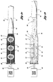
- an electrothermal gun cartridge 30 is illustrated somewhat schematically as being within a gun 32 and as having a casing 34 with a base end 36 and a projectile end 38 the latter of which supports a projectile 40 to be fired through the tube 42 of the gun.
- the cartridge includes a plasma generator 44 that is constructed in accordance with the present invention to generate a plasma for igniting a propellant 46 that is also located within the casing.
- This plasma generation as is hereinafter more fully described is provided by application of a pulse of electrical energy from a source 48 upon closing of a switch 50.
- the voltage involved is relatively large such as on the order of several kilovolts and produces a current flow of tens of kiloamps such as on the order of 100 kiloamps. This large current flow produces relatively large electromagnetic forces as well as substantial forces due to electrical arcing that generates the plasma.
- the construction of the plasma generator as is hereinafter more fully described is capable of withstanding these forces while nevertheless providing the plasma generation at the designed location.
- the propellant 46 includes a fuel and an oxidizer, such as a slurry of aluminum powder and water, and burns in a time on the order of about one to several milliseconds as opposed to the much faster combustion through shock propagation involved with explosion which takes place in microseconds.
- FIG. la there are a plurality of sites 52 along the length of the plasma generator where the plasma is generated to ignite the propellant 46. While the construction of the plasma generator 44 has applicability to even a single site of plasma generation, the ability to generate plasma at multiple sites that are precisely located for igniting the propellant advantageously provides effective cartridge operation. Ignition of the propellant by the plasma as shown in FIG. la generates heated and pressurized gas that is schematically indicated by 54 in FIG. 1b and causes expansion in the direction indicated by arrows 56 to launch the projectile 40.
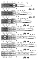
- the plasma generator 44 is constructed to provide sequential generation of the plasma at the sites 52 as illustrated in FIGS. 2a-2g. More specifically, the site 52 immediately adjacent the projectile 40 is first fired as shown in FIG. 2a to ignite the adjacent propellant 46 and generate the gas 54 shown in FIG. 2b so that the expansion shown by arrows 56 begins the projectile movement. After the initial firing, the next site 52 generates a plasma as shown in FIG. 2c to ignite the adjacent propellant 46 and generate additional heated and pressurized gas 56 that continues the expansion shown by arrows 56 and the further movement of the projectile 40. The next site 52 adjacent the base end 36 of the casing is fired as shown in FIG. 2a to ignite the adjacent propellant 46 and generate further gas that continues the expansion as shown in FIG. 2f after which all of the propellant is ignited and generates heated and pressurized gas for completion of the firing as shown in FIG. 2g.
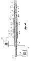
- one embodiment of the plasma generator 44 for the electrothermal gun cartridge previously described includes an elongated metallic rod member 58 extending along the central axis A of the plasma generator.
- An elongated metallic tube member 60 of the plasma generator extends around the rod member 58 in a spaced relationship thereto and a coaxially relationship with the rod member.
- the tube member 60 has an axial gap 62 at each site 52 of electrical arcing that generates the plasma.
- An elongated annular insulator 64 of synthetic resin is located between and in engagement with both elongated metallic members 58 and 60 such that an electrical voltage applied along the one metallic member 60 generates an electrical arc at the axial gap 62 thereof to provide the plasma while the insulator 64 and other metallic member 58 provide support for the elongated metallic member 60.
- the tube member 60 has an insulative covering 66 extending over its surface except at the arc sites 52 and may be provided by a suitable dielectric adhesive tape that covers the plasma generator 44 generally between its opposite ends.
- the rod member 58 and tube member 60 have an electrical connection 68 such as by threading to each other.
- the plasma generator 44 is provided with an electrical rod member connection 70 and an electrical tube member connection 72. Electrical flow through the plasma generator is thus along the rod member 58 as well as along the tube member 60 which has the axial gaps 52 where the electrical arc is generated at the arc sites 52.
- both the rod member 58 and the tube member 60 are preferably constructed from a high strength copper alloy such as of copper and aluminum oxide as available under the trademark GlidCop from SCM Metal Products, Inc. of Research Triangle Park, North Carolina, United States of America.
- the insulator 64 is preferably made by injection molding thereof in situ between the rod and tube members 58 and 60 while also providing the additional insulator material at the arc sites 52 as shown. Such molding is best performed by roughening the outer surface of the rod member 58 and the inner surface of the tube member 60 to enhance the support provided by the insulator 64 between the rod and tube members. This is the preferred construction for manufacturing the insulator 64 even though other possibilities exist such as, for example, the use of tubular plastic sleeves that are inserted between the rod and tube member and then preferably bonded thereto as well as having suitable injection of additional plastic at the arc sites 52 as is hereinafter more fully apparent.
- the preferred material for manufacturing the insulator 64 is a thermoplastic alloy of high strength such as an alloy of polybutylene therephthalate and polycarbonate as available from the General Electric Company of Pittsfield, Massachusetts, United States of America under its trademark Xenoy with its product designation 5220 resin.
- the plasma generator 44 has the axial gap 62 provided with a fuse 74 which, as disclosed are wires having opposite ends secured to the tube member 60 to provide electrical connection thereto as best illustrated in FIGS. 5 and 6.
- These wire type fuses 74 need only be relatively small in diameter, on the order of about one hundredth of an inch or so, to establish the electrical flow that upon burning away of the fuse initiates the arc to generate the plasma as previously described. While the arc generation can be established in some cases by an air gap, it is preferable to utilize a fuse to ensure consistency in timing and in the generation of the arc that produces the plasma. As illustrated, there are fuses 74 spaced circumferentially about the plasma generator 44 as shown in FIG.
- the fuses 74 at each site will have the same size as each other so as to burn away at the same time. Furthermore, when the arc initiation is to be sequential as previously described in connection with FIGS. 2a-2g, the fuses 74 will have a progressively increasing size from the projectile end of the plasma generator toward the base end thereof so that the arc initiation proceeds as previously described. More specific with reference to FIG. 5, the initial arc initiation as previously described in connection with FIG.
- the fuse 74 is also possible for the fuse 74 to be provided by a coating 76 of an electrically conductive material such as carbon that can be sprayed to extend between the portions of the tube member adjacent the axial gap 62.
- a coating 76 of an electrically conductive material such as carbon that can be sprayed to extend between the portions of the tube member adjacent the axial gap 62.
- Such a construction of the fuse by this coating does not as readily lend itself to the sequentially operation previously described in connection with FIGS. 2a-2g as compared to the wire fuse construction since it is not as easy to control the cross-sectional area of the fuse as is the case when the wires of a predetermined diameter are utilized.
- the coating construction does readily lend itself to easy provision of the fuse for use in the simultaneous initiation of the electrical arc and the resultant plasma and through suitable control may, in fact, be utilized to provide the sequential arc initiation.
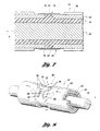
- another modification of the plasma generator has the tube member 58 provided with generally helically extending portions 78 of opposite pitch at opposite sides of the axial gap 62.
- the electrical current flowing along these helically extending portions 78 has an azimuthal component about the central axis A and thereby produces a radial magnetic field with respect to the central axis A, which due to the opposite pitches on opposite sides of the axial gap 62 are additive rather than cancelling each other out.
- the axially flowing current across the axial gap 62 through the radial magnetic field is subjected to an azimuthal force as shown by arrow 80 to provide a rotation to the electrical arc as schematically indicated by 82.
- Such rotation of the electrical arc distributes the plasma as generated to thereby provide uniform distribution of the igniting of the propellant.
- the rod member 58 is the one elongated metallic member having the axial gap 62 at which the electrical arc is generated as opposed to the tube member 60 as with the previously described embodiment.
- current flowing along the rod member 58 generates the electrical arc at each axial gap 62 of the associated site 52 as opposed to the current flowing along the tube member.
- This embodiment like the previously described embodiment preferably has a fuse 74 at each of its sites 52 so as to ensure precisely controlled timing of the arc initiation.
- these fuses 74 may have the same cross-sectional area as each other to provide simultaneous initiation of the electrical arc or may have a progressively increasing cross-sectional area from the right toward the left to provide the sequential initiation of the electrical arc as also previously described.
- One way in which to control the size of the fuses 74 is to provide drilled holes 84 from opposite sides while leaving the central portion of the rod member 58 to provide the fuse 74.
- the holes 84 will thus all terminate at the same depth to leave the same amount of material for each fuse 74; whereas for the sequential operation the holes 84 will be progressively shallower from the right toward the left to leave a greater cross-sectional area.
- Provision of the holes 84 also provides openings through both the elongated metallic tube member 60 and the elongated annular insulator 64 through which the plasma generated by the electrical arc can flow outwardly as depicted in FIG. 11 wherein the holes 84 are somewhat modified and shown as being bored square rather than round which is the case in FIG. 10.
- the plasma generator 44' is illustrated viewed along the direction of holes 84 and has the same construction previously described except that the fuse 74 is also shown as having different sizes 74a, 74c and 74e for providing sequentially fuse burning and arc initiation, and the fuse is also shown as having its web shape extending parallel to the direction of the holes 84 rather than across the direction of the holes.
- the plasma generator 44' is illustrated view along the direction of the hole 84 and having the same construction as generally previously described in connection with FIGS. 9-12 except that its fuse 74 is provided by an electrically conductive coating 76 such as of carbon as previously described in connection with the embodiment of FIG. 7.
- This electrically conductive carbon coating 76 extends between the portions of the rod member 58 at its axial gap 62 to provide the fuse 74 that burns away as the electrical voltage is applied to generate the arc that provides the plasma.
- FIG. 10 Each of the embodiments of FIGS. 9-13 as best illustrated in FIG. 10 has its insulator 64 completely insulating the rod and tube members 58 and 60 from each other which, adjacent the sites 52 is provided by annular insulator portions 86 so that there can be no electrical arcing in a radial direction with respect to the axis A. Also, it is best to fill the holes 84 with a suitable filler 88 (FIG. 9) such as a foam or another plastic that blows away when the electrical arc is established to generate the plasma.
- a suitable filler 88 FIG. 9
- FIGS. 14-17 another embodiment of the plasma generator 44'a has generally the same construction as described in connection with FIGS. 9-13 except as will be noted.
- the current must flow along both the rod member 58 and the tube member 60 but the construction does not completely isolate these members electrically from each other after the filler 88 blows away as the fuse 74 bursts.
- the electrical current flow then as shown in FIG. 16 also flows between the rod member 58 and the tube member 60 to provide a shunting in addition to a small amount of continual axial current flow along the entire length of the plasma generator through both the rod member and the tube member due to the axial arcing.
- the radial arcing is thus transverse to the central axis A of the plasma generator between the elongated metallic rod and tube members 58 and 60 as the electrical arc is established at the axial gap 62 of the rod member.
- the plasma generator 44'a may also have its electrical arc site 52 constructed with the elongated metallic tube member 60 having helically extending portions 90 provided by helically extending slots 92 to provide the electrical current flowing along the helical portions with an azimuthal component that provides an axially extending magnetic field.
- the radial current flowing between the rod and tube members 58 and 60 through the axially extending magnetic field is subjected to an azimuthal force about axis A such that the electrical arc rotates and thereby distributes the plasma generated.
- the slots 92 it is also necessary for the slots 92 to extend through the insulator 64 so that the arc and plasma generated can exit the plasma generator.
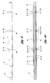
- another embodiment of the plasma generator 44" has the same construction as the embodiment of FIGS. 3-6 but also has a second elongated metallic tube member 94 that receives the first tube member 60 in a spaced relationship thereto and a coaxial relationship therewith.
- a second elongated annular insulator 96 of synthetic resin is located between and engagement with both elongated metallic tube members 60 and 94 in the same manner previously described in connection with the first insulator 64.
- the second elongated metallic tube member 94 has a pair of sites 52 where axial gaps 62 of the second tube member 94 are located with associated fuses 74 for use in arc initiation in the same manner previously described.
- the fuse sites 52 along the first tube member 60 there are two of the fuse sites 52 along the first tube member 60 and there are also two of the fuse sites 52 along the second tube member 94.
- the electrical connection 68 between the rod member 58 and the first tube member 60 there is also an electrical connection 98 between the first tube member 60 intermediate its ends and the right end of the second tube member 94.
- the left end of the second tube member 94 has another electrical connection 100.
- the source of electrical voltage 48 as with the previously described embodiment is connected between the electrical connection 70 and the electrical connection 72 to generate the electrical arcs and the plasma at the two sites 52 associated with the rod member 58 and the first tube member 60, while another source of electrical voltage 102 having an associated switch 104 extends between the electrical connection 72 and the electrical connection 100 at the left end of the second tube member 94.
- This construction of the plasma generator 44" further enhances the capability of timing the initiation of the electrical arc and hence the generation of the plasma for igniting the plasma.
- each of the sites 52 associated with each source of electrical voltage can have their associated fuse 74 sized to burn simultaneous with each other or sequentially in addition to the flexibility in timing and the level of power possible by use of the two sources of electrical voltage 48 and 102.
- the cartridge 30 is illustrated as having a single plasma generator 44 which may be of any of the constructions previously described and is mounted by the base end 36 of the cartridge casing which is made of high strength electrically conductive metal and is electrically connected to one terminal of the associated electrical voltage source through a suitable contact for the firing.
- An electrically conductive metallic base plate 106 is covered with a suitable insulation so as to be electrically isolated from the base end 36 which also has an insulative coating at the interface.
- An insulation plate 108 of high strength metal has an insulative coating that isolates it from all of the other components and prevents electrical contact between the connectors 70 and 72 of the plasma generator 44.
- a mounting plate 110 has an electrical insulative coating but is electrically connected to the base end 36 by three sets of bolts 112 and sleeves 114, only one of which set is shown. More specifically, the sleeve 114 is made of a soft electrically conductive metal such as copper and has an outer electrically insulative coating so as to be isolated from the insulation plate 108 and the base end 36 while extending through associated holes 116 and 118 thereof. The opposite ends of the sleeve 114 are bare metal that is electrically contacted with the mounting plate 110 and the base plate 106 with the associated bolt 112 extending through a hole 120 in the mounting plate 110 and is threaded into a hole 122 in the base plate 106 such that the torquing of the bolt effectively establishes the electrical contact.
- the plasma generator 44 extends through holes 124 and 126 in the insulation and mounting plates 108 and 110 respectively, and has its connector 70 provided with a threaded construction that is received by a threaded hole 124 at the center of the cartridge base end 36 so as to establish electrical contact.
- the electrical connector 72 is electrically connected to the mounting plate 110 at the hole 126 such as by a press fit. Electrical connectors 70 and 72 can establish the electrical connection either by threaded or press fits as well as any other suitable type of electrical connection that has the capability of withstanding the high electrical current and shock that is present during firing of the cartridge.
- the cartridge 30 prefferably has a plurality of the plasma generators 44 such as the three illustrated with each being mounted by the base end of the cartridge in the same manner previously described in connection with FIGS. 20 and 21 except for the location of mounting being at three circumferentially spaced locations rather than the single central location previously described.
Landscapes
- Engineering & Computer Science (AREA)
- General Engineering & Computer Science (AREA)
- Physics & Mathematics (AREA)
- Electromagnetism (AREA)
- Plasma & Fusion (AREA)
- Plasma Technology (AREA)
- Particle Formation And Scattering Control In Inkjet Printers (AREA)
Claims (10)
- Plasmagenerator (44) für eine elektrothermische Gewehrpatrone (30), bestehend ausdadurch gekennzeichnet, daßeinem langgestreckten Stabelement (58) aus Metall, das sich längs einer zentralen Achse (A) des Plasmagenerators (44) erstreckt;einem langgestreckten Rohrelement (60) aus Metall, das sich um das Stabelement (58) beabstandet und koaxial hierzu erstreckt;
das Rohrelement (60) wenigstens einen axialen Spalt (62) über dessen Länge hat; und ein langgestreckter ringförmiger Isolator (64) aus synthetischem Harz zwischen beiden langgestreckten Elementen (58, 60) aus Metall derart angeordnet ist und an diesen angrelft, daß eine längs des Rohrelements (60) angelegte elektrische Spannung einen elektrischen Lichtbogen an dessen axialem Spalt (62) bewirkt, um ein Plasma zu erzeugen, während der Isolator (64) und das Stabelement (58) eine Unterstützung für das Rohrelement (60) bilden. - Plasmagenerator (44) für eine elektrothermische Gewehrpatrone (30) nach Anspruch 1, bei dem der axiale Spalt (62) eine Sicherung (74) hat, die abbrennt, wenn die Spannung an das Rohrelement (60) angelegt wird, um die Erzeugung des elektrischen Lichtbogens und damit des Plasmas zu erleichtern.
- Plasmagenerator (44) für eine elektrothermische Gewehrpatrone (30) nach Anspruch 1 oder 2, der wenigstens mehrere axiale Spalte (62) zur Erzeugung getrennter elektrischer Lichtbogen an von einander axial beabstandeten Stellen aufweist.
- Plasmagenerator (44) für eine elektrothermische Gewehrpatrone (30) nach Anspruch 3, bei dem die axialen Spalte (62) so aufgebaut sind, daß getrennte elektrische Lichtbogen an den axialen Spalten (62) gleichzeitig erzeugt werden.
- Plasmagenerator (44) für eine elektrothermische Gewehrpatrone (30) nach Anspruch 3, bei dem die axialen Spalte (62) so aufgebaut sind, daß die getrennten elektrischen Lichtbögen an den axialen Spalten (62) aufeinanderfolgend erzeugt werden.
- Plasmagenerator (44) für eine elektrothermische Gewehrpatrone (30) nach Anspruch 3, bei dem der Isolator (62) die langgestreckten Elemente (58, 60) aus Metall an den axialen Spalten (62) vollständig voneinander isoliert, so daß keine elektrische Lichtbogenbildung dazwischen erfolgt, wenn die elektrischen Lichtbogen an den axialen Spalten (62) erzeugt werden.
- Plasmagenerator (44) für eine elektrothermische Gewehrpatrone (30) nach Anspruch 1 oder 2, bei dem das Rohrelement (60) etwa spiralförmig verlaufende Abschnitte (78) mit entgegengesetzter Steigung an gegenüberliegenden Seiten des axialen Spalts (62) hat, um eine Drehbewegung des elektrischen Lichtbogens hervorzurufen.
- Plasmagenerator (44) für eine elektrothermische Gewehrpatrone (30) nach Anspruch 7, der mehrere axiale Spalte (62) und zugehörige spiralförmig verlaufende Abschnitte (78) aufweist.
- Plasmagenerator (44') für eine elektrothermische Gewehrpatrone (30) nach Anspruch 1 oder 2, weiterhin aufweisend ein zweites langgestrecktes Rohrelement (94) aus Metall, das das erst erwähnte langgestreckte Rohrelement (60) aus Metall beabstandet und koaxial dazu aufnimmt, einen zweiten langgestreckten ringförmigen Isolator (96) aus synthetischem Harz, der sich zwischen den langgestreckten Rohrelementen (60, 94) aus Metall befindet und an diesem angreift, wobei das zweite langgestreckte Rohrelement (94) aus Metall wenigstens einen axialen Spalt (62) zur Erzeugung eines elektrischen Lichtbogens hat, um ein Plasma zu erzeugen, wenn eine elektrische Spannung über seine Länge angelegt wird.
- Plasmagenerator für eine elektrothermische Gewehrpatrone (30) nach Anspruch 9, bei dem das erste und zweite langgestreckte Rohrelement (60, 94) aus Metall jeweils mehrere axiale Spalte (62) aufweist.
Applications Claiming Priority (3)
| Application Number | Priority Date | Filing Date | Title |
|---|---|---|---|
| US08/238,433 US5549046A (en) | 1994-05-05 | 1994-05-05 | Plasma generator for electrothermal gun cartridge |
| US238433 | 1994-05-05 | ||
| PCT/US1995/002969 WO1995030874A1 (en) | 1994-05-05 | 1995-03-08 | Plasma generator for electrothermal gun cartridge |
Publications (3)
| Publication Number | Publication Date |
|---|---|
| EP0758441A1 EP0758441A1 (de) | 1997-02-19 |
| EP0758441A4 EP0758441A4 (de) | 1997-07-02 |
| EP0758441B1 true EP0758441B1 (de) | 1998-10-28 |
Family
ID=22897871
Family Applications (1)
| Application Number | Title | Priority Date | Filing Date |
|---|---|---|---|
| EP95913995A Expired - Lifetime EP0758441B1 (de) | 1994-05-05 | 1995-03-08 | Plasma generator für elektrothermische patronenpfropfe |
Country Status (7)
| Country | Link |
|---|---|
| US (1) | US5549046A (de) |
| EP (1) | EP0758441B1 (de) |
| KR (1) | KR100290556B1 (de) |
| AU (1) | AU682951B2 (de) |
| DE (1) | DE69505654T2 (de) |
| IL (1) | IL113035A (de) |
| WO (1) | WO1995030874A1 (de) |
Families Citing this family (22)
| Publication number | Priority date | Publication date | Assignee | Title |
|---|---|---|---|---|
| US5503081A (en) * | 1993-11-22 | 1996-04-02 | Fmc Corp | Annular plasma injector |
| DE19617895C2 (de) * | 1996-05-04 | 1998-02-26 | Rheinmetall Ind Ag | Plasmainjektionsvorrichtung |
| FR2764369B1 (fr) * | 1997-06-04 | 1999-12-17 | Lasers Et Tech Avancees Bureau | Systeme de mise a feu par plasma d'une munition d'artillerie |
| FR2768810B1 (fr) * | 1997-09-24 | 1999-12-03 | Giat Ind Sa | Composant d'allumage pour composition pyrotechnique ou charge propulsive |
| US6119599A (en) * | 1998-08-19 | 2000-09-19 | United Defense, L.P. | Sequential arc surface injector |
| SE517704C2 (sv) * | 1999-05-10 | 2002-07-09 | Tzn Forschung & Entwicklung | Patron med elektrotermisk tändanordning |
| SE517737C2 (sv) * | 1999-05-11 | 2002-07-09 | Tzn Forschung & Entwicklung | Patron med elektrotermisk antändningsanordning |
| FR2824898B1 (fr) * | 2001-05-18 | 2003-09-12 | Giat Ind Sa | Culot pour munition destine a recevoir un allumeur electrique |
| DE10140599A1 (de) * | 2001-08-18 | 2003-03-06 | Rheinmetall W & M Gmbh | Patrone |
| FR2844873B1 (fr) * | 2002-09-25 | 2006-11-24 | Giat Ind Sa | Inflammateur a double effet et procede d'allumage mettant en oeuvre un tel inflammateur |
| US6988450B1 (en) * | 2002-09-25 | 2006-01-24 | The United States Of America As Represented By The Secretary Of The Army | Anti-personnel ammunition |
| US6805055B1 (en) | 2003-06-25 | 2004-10-19 | Gamma Recherches & Technologies Patent Sa | Plasma firing mechanism and method for firing ammunition |
| US7305912B2 (en) * | 2004-12-30 | 2007-12-11 | Bae Systems Advanced Technologies, Inc. | Chemically driven hydrogen gun |
| RU2348004C2 (ru) * | 2007-01-17 | 2009-02-27 | Российская Федерация, от имени которой выступает государственный заказчик - Министерство обороны Российской Федерации | Способ воспламенения метательного заряда в каморе ствола артиллерийского орудия с безгильзовым заряжанием и устройство для его осуществления |
| DE202009014949U1 (de) | 2009-01-26 | 2010-10-07 | Oao Znjj "Burevestnik" | Einrichtung zur Zündung der Wurfladung in der Geschosskammer eines Artilleriesystems mit hülsenloser Ladung |
| DE102009043491A1 (de) * | 2009-09-30 | 2011-04-07 | Rheinmetall Waffe Munition Gmbh | Aktivierungseinheit für munitionsfreie Scheinziele |
| US9939235B2 (en) | 2013-10-09 | 2018-04-10 | Battelle Energy Alliance, Llc | Initiation devices, initiation systems including initiation devices and related methods |
| US9360285B1 (en) * | 2014-07-01 | 2016-06-07 | Texas Research International, Inc. | Projectile cartridge for a hybrid capillary variable velocity electric gun |
| RU2571459C1 (ru) * | 2014-11-21 | 2015-12-20 | Михаил Иосифович Фильковский | Устройство для воспламенения метательного заряда |
| CN111929290A (zh) * | 2019-05-13 | 2020-11-13 | 中国科学院上海硅酸盐研究所 | 钨丝电热蒸发-大气压辉光放电原子发射光谱装置 |
| US12312956B2 (en) | 2020-09-03 | 2025-05-27 | Petram Technologies, Inc. | Robust plasma blast probe tip |
| US11536124B2 (en) * | 2020-09-03 | 2022-12-27 | Petram Technologies, Inc. | Sliced and elliptical head probe for plasma blast applications |
Family Cites Families (15)
| Publication number | Priority date | Publication date | Assignee | Title |
|---|---|---|---|---|
| US803131A (en) * | 1905-02-25 | 1905-10-31 | Francis I Du Pont | Method of firing a powder charge simultaneously throughout its length. |
| US3143069A (en) * | 1960-05-18 | 1964-08-04 | Electronic Res And Dev Corp | Exploding tape |
| US3251216A (en) * | 1963-06-21 | 1966-05-17 | Amp Inc | Method and apparatus for applying electrical connectors to conductors |
| US3169482A (en) * | 1963-08-14 | 1965-02-16 | Eitelmccullough Inc | Electro explosive device having a surface spark gap |
| US4715261A (en) * | 1984-10-05 | 1987-12-29 | Gt-Devices | Cartridge containing plasma source for accelerating a projectile |
| US4974487A (en) * | 1984-10-05 | 1990-12-04 | Gt-Devices | Plasma propulsion apparatus and method |
| US4711154A (en) * | 1985-10-31 | 1987-12-08 | Fmc Corporation | Combustion augmented plasma pressure amplifier |
| US4895062A (en) * | 1988-04-18 | 1990-01-23 | Fmc Corporation | Combustion augmented plasma gun |
| DE3816300A1 (de) * | 1988-05-13 | 1989-11-23 | Tzn Forschung & Entwicklung | Kartusche fuer elektrothermische abschussvorrichtungen |
| US5072647A (en) * | 1989-02-10 | 1991-12-17 | Gt-Devices | High-pressure having plasma flow transverse to plasma discharge particularly for projectile acceleration |
| US5235127A (en) * | 1990-08-30 | 1993-08-10 | Findley Stephan D | Weapon discharge simulation system and electrostatically discharged pyrotechnic cartridge for use in said system |
| US5171932A (en) * | 1991-09-30 | 1992-12-15 | Olin Corporation | Electrothermal chemical propulsion apparatus and method for propelling a projectile |
| US5261315A (en) * | 1991-11-04 | 1993-11-16 | Fmc Corporation | Precision capillary discharge switch |
| US5231242A (en) * | 1991-11-18 | 1993-07-27 | Fmc Corporation | Plasma injection and distribution systems |
| US5444208A (en) * | 1993-03-29 | 1995-08-22 | Fmc Corporation | Multiple source plasma generation and injection device |
-
1994
- 1994-05-05 US US08/238,433 patent/US5549046A/en not_active Expired - Fee Related
-
1995
- 1995-03-08 DE DE69505654T patent/DE69505654T2/de not_active Expired - Fee Related
- 1995-03-08 AU AU21174/95A patent/AU682951B2/en not_active Ceased
- 1995-03-08 EP EP95913995A patent/EP0758441B1/de not_active Expired - Lifetime
- 1995-03-08 WO PCT/US1995/002969 patent/WO1995030874A1/en not_active Ceased
- 1995-03-08 KR KR1019960706129A patent/KR100290556B1/ko not_active Expired - Fee Related
- 1995-03-19 IL IL11303595A patent/IL113035A/xx not_active IP Right Cessation
Also Published As
| Publication number | Publication date |
|---|---|
| AU2117495A (en) | 1995-11-29 |
| IL113035A0 (en) | 1995-06-29 |
| DE69505654T2 (de) | 1999-07-15 |
| WO1995030874A1 (en) | 1995-11-16 |
| IL113035A (en) | 2000-10-31 |
| KR100290556B1 (ko) | 2001-06-01 |
| EP0758441A1 (de) | 1997-02-19 |
| DE69505654D1 (de) | 1998-12-03 |
| EP0758441A4 (de) | 1997-07-02 |
| KR970702986A (ko) | 1997-06-10 |
| AU682951B2 (en) | 1997-10-23 |
| US5549046A (en) | 1996-08-27 |
Similar Documents
| Publication | Publication Date | Title |
|---|---|---|
| US5549046A (en) | Plasma generator for electrothermal gun cartridge | |
| JP3649251B2 (ja) | シリアル アーク プラズマ インジェクタ | |
| US4493297A (en) | Plasma jet ignition device | |
| KR100308081B1 (ko) | 플라즈마파암용 전력충격쎌 | |
| GB2349939A (en) | Elecrothermally ignited cartridge | |
| KR20010098795A (ko) | 전열 점화 장치를 구비한 카트리지 | |
| US20020134767A1 (en) | Plasma torch comprising electrodes separated by an air gap and igniter incorporating same | |
| US6119599A (en) | Sequential arc surface injector | |
| US6332402B1 (en) | Ammunition cartridge with electric propellant ignition | |
| US6691621B2 (en) | Ignition device for a propellant charge | |
| MX2007004718A (es) | Bujia doble coaxial. | |
| GB2332736A (en) | Plasma burning device for weapon systems | |
| US6745697B2 (en) | Cartridge | |
| EP1444478B1 (de) | Transversal angeordneter plasmastrahlzünder | |
| KR100292386B1 (ko) | 전열 포와 탄약 용의 전력 공급 어셈블리 | |
| KR20010098796A (ko) | 전열 점화 장치 및 그 제조 방법 | |
| US5003884A (en) | Hollow or projectile charge | |
| RU2150652C1 (ru) | Коаксиальный ускоритель сивкова | |
| EP0408089B1 (de) | Vorrichtung zum Initiieren von Verbrennung in einer Brennkraftmaschine | |
| US11725896B2 (en) | Repeatable plasma generator | |
| DE19936649C2 (de) | Patrone | |
| DE19936650C2 (de) | Patrone | |
| BG62416B1 (bg) | Унитарен боеприпас |
Legal Events
| Date | Code | Title | Description |
|---|---|---|---|
| PUAI | Public reference made under article 153(3) epc to a published international application that has entered the european phase |
Free format text: ORIGINAL CODE: 0009012 |
|
| 17P | Request for examination filed |
Effective date: 19960925 |
|
| AK | Designated contracting states |
Kind code of ref document: A1 Designated state(s): DE FR GB SE |
|
| A4 | Supplementary search report drawn up and despatched |
Effective date: 19970521 |
|
| AK | Designated contracting states |
Kind code of ref document: A4 Designated state(s): DE FR GB SE |
|
| 17Q | First examination report despatched |
Effective date: 19970731 |
|
| GRAG | Despatch of communication of intention to grant |
Free format text: ORIGINAL CODE: EPIDOS AGRA |
|
| GRAG | Despatch of communication of intention to grant |
Free format text: ORIGINAL CODE: EPIDOS AGRA |
|
| GRAH | Despatch of communication of intention to grant a patent |
Free format text: ORIGINAL CODE: EPIDOS IGRA |
|
| GRAH | Despatch of communication of intention to grant a patent |
Free format text: ORIGINAL CODE: EPIDOS IGRA |
|
| GRAA | (expected) grant |
Free format text: ORIGINAL CODE: 0009210 |
|
| AK | Designated contracting states |
Kind code of ref document: B1 Designated state(s): DE FR GB SE |
|
| REF | Corresponds to: |
Ref document number: 69505654 Country of ref document: DE Date of ref document: 19981203 |
|
| ET | Fr: translation filed | ||
| PLBE | No opposition filed within time limit |
Free format text: ORIGINAL CODE: 0009261 |
|
| STAA | Information on the status of an ep patent application or granted ep patent |
Free format text: STATUS: NO OPPOSITION FILED WITHIN TIME LIMIT |
|
| 26N | No opposition filed | ||
| PGFP | Annual fee paid to national office [announced via postgrant information from national office to epo] |
Ref country code: FR Payment date: 20010219 Year of fee payment: 7 |
|
| PGFP | Annual fee paid to national office [announced via postgrant information from national office to epo] |
Ref country code: DE Payment date: 20010220 Year of fee payment: 7 |
|
| PGFP | Annual fee paid to national office [announced via postgrant information from national office to epo] |
Ref country code: GB Payment date: 20010221 Year of fee payment: 7 |
|
| PGFP | Annual fee paid to national office [announced via postgrant information from national office to epo] |
Ref country code: SE Payment date: 20010222 Year of fee payment: 7 |
|
| REG | Reference to a national code |
Ref country code: GB Ref legal event code: IF02 |
|
| PG25 | Lapsed in a contracting state [announced via postgrant information from national office to epo] |
Ref country code: GB Free format text: LAPSE BECAUSE OF NON-PAYMENT OF DUE FEES Effective date: 20020308 |
|
| PG25 | Lapsed in a contracting state [announced via postgrant information from national office to epo] |
Ref country code: SE Free format text: LAPSE BECAUSE OF NON-PAYMENT OF DUE FEES Effective date: 20020309 |
|
| PG25 | Lapsed in a contracting state [announced via postgrant information from national office to epo] |
Ref country code: DE Free format text: LAPSE BECAUSE OF NON-PAYMENT OF DUE FEES Effective date: 20021001 |
|
| EUG | Se: european patent has lapsed |
Ref document number: 95913995.7 |
|
| GBPC | Gb: european patent ceased through non-payment of renewal fee |
Effective date: 20020308 |
|
| PG25 | Lapsed in a contracting state [announced via postgrant information from national office to epo] |
Ref country code: FR Free format text: LAPSE BECAUSE OF NON-PAYMENT OF DUE FEES Effective date: 20021129 |
|
| REG | Reference to a national code |
Ref country code: FR Ref legal event code: ST |