EP0758134A2 - Steuerung für elektrolumineszentes Lampenpaneel mit mehrere Schaltungen - Google Patents
Steuerung für elektrolumineszentes Lampenpaneel mit mehrere Schaltungen Download PDFInfo
- Publication number
- EP0758134A2 EP0758134A2 EP96305760A EP96305760A EP0758134A2 EP 0758134 A2 EP0758134 A2 EP 0758134A2 EP 96305760 A EP96305760 A EP 96305760A EP 96305760 A EP96305760 A EP 96305760A EP 0758134 A2 EP0758134 A2 EP 0758134A2
- Authority
- EP
- European Patent Office
- Prior art keywords
- segments
- indicia
- group
- panel
- functional
- Prior art date
- Legal status (The legal status is an assumption and is not a legal conclusion. Google has not performed a legal analysis and makes no representation as to the accuracy of the status listed.)
- Granted
Links
Images

Classifications
-
- H—ELECTRICITY
- H01—ELECTRIC ELEMENTS
- H01H—ELECTRIC SWITCHES; RELAYS; SELECTORS; EMERGENCY PROTECTIVE DEVICES
- H01H13/00—Switches having rectilinearly-movable operating part or parts adapted for pushing or pulling in one direction only, e.g. push-button switch
- H01H13/70—Switches having rectilinearly-movable operating part or parts adapted for pushing or pulling in one direction only, e.g. push-button switch having a plurality of operating members associated with different sets of contacts, e.g. keyboard
-
- H—ELECTRICITY
- H05—ELECTRIC TECHNIQUES NOT OTHERWISE PROVIDED FOR
- H05B—ELECTRIC HEATING; ELECTRIC LIGHT SOURCES NOT OTHERWISE PROVIDED FOR; CIRCUIT ARRANGEMENTS FOR ELECTRIC LIGHT SOURCES, IN GENERAL
- H05B44/00—Circuit arrangements for operating electroluminescent light sources
-
- H—ELECTRICITY
- H01—ELECTRIC ELEMENTS
- H01H—ELECTRIC SWITCHES; RELAYS; SELECTORS; EMERGENCY PROTECTIVE DEVICES
- H01H2219/00—Legends
- H01H2219/002—Legends replaceable; adaptable
- H01H2219/018—Electroluminescent panel
-
- Y—GENERAL TAGGING OF NEW TECHNOLOGICAL DEVELOPMENTS; GENERAL TAGGING OF CROSS-SECTIONAL TECHNOLOGIES SPANNING OVER SEVERAL SECTIONS OF THE IPC; TECHNICAL SUBJECTS COVERED BY FORMER USPC CROSS-REFERENCE ART COLLECTIONS [XRACs] AND DIGESTS
- Y02—TECHNOLOGIES OR APPLICATIONS FOR MITIGATION OR ADAPTATION AGAINST CLIMATE CHANGE
- Y02B—CLIMATE CHANGE MITIGATION TECHNOLOGIES RELATED TO BUILDINGS, e.g. HOUSING, HOUSE APPLIANCES OR RELATED END-USER APPLICATIONS
- Y02B20/00—Energy efficient lighting technologies, e.g. halogen lamps or gas discharge lamps
- Y02B20/30—Semiconductor lamps, e.g. solid state lamps [SSL] light emitting diodes [LED] or organic LED [OLED]
Definitions
- the present invention relates generally to illumination of indicia on a control panel and, more particularly, to controlled illumination by electroluminescent lamp (EL) panel paths of audio system bezels having optical indicia on the housing or on the controls for a variety of audio system functional modes.
- EL electroluminescent lamp
- Control panels often have background illumination in order to expose graphics or optical indicia that identify the functions related to particular controls on the control panel.
- the traditional choice for illuminating control panel graphics located above, on or below a button or switch actuator, particularly in motor vehicle audio entertainment systems, has been an arrangement of incandescent lamps and light pipes, for example, as shown in U.S. Patent No. 4,449,024.
- a light pipe may be formed as a transparent or translucent panel but must be specially constructed with reflecting baffle surfaces and the like to direct light rays in particular directions at various distances and locations from an incandescent light source.
- the substantial engineering, design and implementation of the light pipe requires a long lead time, particularly with a complex light path arrangement for audio system control bezels. Accordingly, such structures were correspondingly expensive.
- the previous light pipe systems do not offer a balance of light colour and intensity throughout the light pipe and they provide little or no differentiation of function graphics carried on a button actuator.
- the illumination is unable to differentiate or selectively illuminate the operable controls of an audio system bezel or control panel during operation of a radio receiver in a particular functional mode.
- An actuator for selectable functions operable during functional modes such as the forward or reverse function actuator to be used during operation of a cassette tape player or a compact disc player, may have other functions once a different operating mode has been selected on the control panel.
- the light reflective surfaces arranged to reflect light toward a push button face after travelling transversely behind the buttons through the light pipe introduce illumination losses that reduce visibility identification of the indicia, distinction between the indicia, and a user's selection of desired control.
- Other known lighting structures include background illumination for translucent or clear button grids where a light source provides background lighting for indicia in the button.
- U.S. Patent Nos. 5,138,119 and 5,149,923 to Demeo disclose tactile dome switches with an illumination diode positioned beneath each dome.
- the illumination is provided by an electroluminescent panel providing back lighting for the indicia.
- U.S. Patent Nos. 4,060,703, 4,320,268 and 4,532,395 disclose keyboard panels in which an electroluminescent panel provides background illumination for the push button indicia. Nevertheless, the previous luminescent panel does not distinguish one set of push buttons from another, even where the push button may be provided with multiple functions in different operating modes of the apparatus.
- the present invention provides an electroluminescent lamp (EL) panel circuit in which at least one electroluminescent lamp panel includes a plurality of discrete segments and a switching power supply that enables the discrete segments to be illuminated in groups particularly configured to control distribution and illumination intensity.
- the segments are contained in a single electroluminescent lamp panel controlled by a single power supply balanced with each of the loads to provide consistent illumination intensity regardless of the functional mode in which the control panel is employed.
- the discrete segments may be provided on multiple independent, separately configured electric lamp panels that are engageable with a driving compatible circuit of the same type to provide consistent illumination intensity throughout a multiple product line.
- the present invention also provides a method for equalising light intensity from a plurality of electroluminescent panel segments formed in at least one electroluminescent lamp panel for a multi-functional control panel having a plurality of functional modes and a plurality of indicia locations relating to each mode.
- the method defines a group of electroluminescent lamp panel segments to be illuminated for each functional mode, including selecting at least one first set of the EL segments, selecting at least one second set of EL panel segments and combining selected first and second sets related to a functional mode; in addition to sizing portions of each segment, determining the mode group having the largest area, and enhancing the area of other mode groups to match the largest area load group.
- the first set of segments includes indicia locations unique to each functional mode.
- the second set of electroluminescent panel segments includes segments associated with at least one common indicia location for at least two functional modes on the control panel.
- an audio system control panel bezel having indicia locations on the bezel as well as on actuators positioned in the bezel includes selective lighting apparatus according to the present invention.
- Multiple function identifying indicia are aligned with electroluminescent lamp panel segments defined by conductive surfaces on the lamp panel.
- a plurality of segments includes at least one first set of electroluminescent lamp panels segments aligned with indicia locations unique to a functional mode, for example, autoset during radio play that is not used for compact disc or tape media operation.
- the plurality of circuits include at least one second set of electroluminescent lamp panel segments aligned with indicia locations associated with at least one common indicia for at least two functional modes, for example, an indicator active during both tape and compact disc functional modes, for example, fast forward and rewind indicators.
- a coupler including an invertor and a plurality of switches or branches, the combined number of invertor paths of switches and branches corresponding in number to the number of segments, is subject to a controller that controls illumination of various portions of the panel and thus the radio bezel in response to a selected functional mode, for example radio operation. Nevertheless, the light intensity from the group of illuminated segments remain substantially constant regardless of whether radio, tape or compact disc operation is selected.
- a single invertor with a transformer drives the load, and the load is balanced with the coupler by matching the areas of the segments in the electroluminescent lamp panel.
- the total area in each group of segments selected for illumination in the EL panel can remain consistent with the group areas selected for illumination on an alternative lamp panel configuration so that alternative or substitute control panel devices can be operated with the same switching power supply.
- the embodiment of the present invention provides a segmented electroluminescent lamp panel particularly arranged for controlled illumination of control panel indicia locations regardless of the functional mode selected for use.
- the embodiment of the present invention provides better illumination control for radio bezel than previously known radio bezel constructions such as those having light pipes.
- the embodiment of the present invention renders a single switching power supply compatible with alternative radio bezel embodiments for example the standard and optional radio selections of analogue radio, digital radio or digital radio with compact disc functional mode as may be made available to a motor vehicle purchaser.
- the present invention provides a highly efficient illumination technique that permits only the operable portions of the indicia on the bezel to be illuminated at a desired level during operation of a particular functional mode.
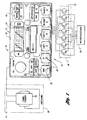
- an audio entertainment system 10 includes a control panel 12 and an illumination circuit 14.
- the illumination circuit 14 includes the electroluminescent lamp panel underlaying a bezel 18.
- the bezel 18 includes a plurality of indicia locations 20, which may be directly carried on actuators as shown at 22 or in locations adjacent actuators as shown at 24. In any event, a plurality of indicia locations 20 both on actuators and on the bezel will be aligned over circuit segments of the electroluminescent lamp panel as will be described in greater detail below.
- the illumination circuit 14 also includes an invertor 26 that converts the motor vehicle supply d.c. voltage, for example, from the headlamp voltage, to an alternating current that drives the lamp panel.
- a bank 28 including a plurality of switches and branches selectively apply the alternating current to a plurality of electroluminescent lamp panel segments at terminal connector 29 with a plurality of terminals (FIG. 2) as will be described in greater detail below in response to the signalling generated in a microprocessor 30.
- the present invention provides a switching power supply that groups EL panel segments for illumination intensity control as described in greater detail below.
- the actuators are buttons carried in openings in the bezel and biased outwardly from the face of the bezel by an elastomeric switch path lying between the light panel 16 and bezel 18.
- the elastomeric switch path includes a wall around the opening that serves to channel light from electroluminescent lamp panel 16 to the optical indicia 20 on the button or the bezel.
- Contacts carried by the elastomeric wall remain spaced apart from the complimentary switch closure.
- the illuminating system for the bezel 18 of the present invention serves to improve identification of controls applicable to each functional mode of the audio system by separately illuminating the applicable controls related to each functional mode of the audio system.
- the electroluminescent lamp panel 16 is preferably made of a microencapsulated phosphor layer intermediate conductive plates, for example, a Durel 3 trim light for a.c. current activation, having surface coated mylar as conductive surfaces. In such a panel, glass beads containing phosphor lie between two conductive layers.
- a plurality of circuit segments may be formed in the electroluminescent panel, for example, by an indium tin oxide layer forming conductive surfaces on opposite sides of the phosphor layer. The segments can be shaped, for example by oblation of portions of the layer, to form a plurality of chargeable areas such as 32,34,36,38,40 and 42 on one side of the microencapsulated phosphor as shown in Figure 2.
- An additional conductive area is formed on another conductive surface on the opposite side of the microencapsulated phosphor as shown at 44 in Figure 3.
- Each of the shaped conductive surfaces connects to a terminal on connector 29 on the electroluminescent lamp panel adapted to be coupled in the illumination circuit.
- the EL panel 16 is divided into enough segments of conductive areas so that selective lighting of the indicia applicable to a functional mode can be achieved without unwanted LIT segments being made visible to the user.
- indicia locations that are unique to one mode of operation are joined in a single segment.
- a plurality of indicia locations unique to the particular functional mode for example, the indicia related to the EJECT, SIDE 1-2, and Dolby noise reduction actuator buttons applicable to the tape functional mode are joined in segment 34.
- Indicia locations such as COMPRESSION and SHUFFLE related strictly to operation of a compact disc player are joined in segment 36.
- functions related uniquely to the radio such as AUTO-SET actuator button indicia and the pre-selected station button indicia numerals 1-6 are aligned with a joined segment 40.
- Additional segments are made by forming conductive paths combining indicia locations to be illuminated for at least two modes of operation.
- indicia used at the TUNE/DISCS actuator enables a single control for use in the radio operation as well as the compact disc player, is illuminated by the conductive surface segment 32.
- segment 38 illuminates indicia when a TAPE functional mode or the CD functional mode is actuated, for example, the actuators operable as rewind and fast forward controls.
- Segment 42 provides illumination for indicia locations used in all functional modes, for example, BASS, TREBLE, BALANCE and FADE controls, PUSH-ON VOLUME control, FM1 and FM2 selector buttons, as well as SEEK, SCAN, TAPE, CD and the forward and reverse arrows.
- Segment 44 which forms the opposite plate of the capacitive segments, may be termed a power feed segment, as will be discussed in detail below.
- the segments are arranged in groups corresponding to the mode of operation. Accordingly, if the radio functional mode is selected, segments 32, 40 and 42 will be supplied to illuminate the appropriate indicia locations. Similarly, circuits must be completed with segments 34, 38 and 42 when the tape functional mode is selected. Similarly, the circuits must be completed with segments 32, 36, 38 and 42 when the compact disc (CD) functional mode has been selected.
- CD compact disc
- the target area can be reduced to limit the power necessary to illuminate the control panel by limiting the area exposed at each indicia location.
- a predetermined level of illumination intensity may limit the amount of reduction that can be achieved to the area. Nevertheless, if possible it may be desirable to limit the area of the target area to the next smallest area covered by an alternative functional mode.
- the area of the other groups of segments is increased to equalise the area offered by each group of combined segments.
- Such equalisation equalises the load to be applied to the driving circuit for the EL panel.
- the segments for unique connections for the modes are expanded initially.
- the additions are made at locations as shown at 46 adjacent to or contiguous with segment areas that are aligned with the indicia locations.
- the use of areas contiguous to the areas aligned to the indicia location enables partitions in the actuators, elastomeric layers or other structures to obscure the additional illumination that may be provided by such areas.
- the additional areas may be located at areas remote from the indicia locations as shown at 48, so that the additional illuminated areas are covered by opaque portions of the bezel.
- the additional conductive surface areas may be phantom areas, that are not aligned with portions of the circuit segment 44 formed as a power feed segment as shown in phantom line at 49, whereby the additional surface area creates a phantom segment that does not illuminate the conductive area 48 when power is applied to the segment. Nevertheless, the phantom segment creates a necessary load in segment 34 to equalise the illumination intensity provided by each group of segments supplied with a drive signal during operation of the selected functional modes.
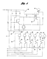
- the invertor 26 that supplies power to the segments includes a switching circuit 60 and a transformer 62.
- the load balance as previously discussed is particularly important to proper illumination intensity as the reactance of the inductive coils in the transformer offsets the reactance of the capacitive load provided by the EL panel segment groups.
- a proper illumination intensity, and a proper colour of generated light which is dependant upon the frequency of the signal flowing through the completed circuit containing the segments, it is generally necessary to design a particular transformer for use in controlling the groups of selected target areas according to conventional design criteria. Accordingly, a coarse adjustment in the transformer may be provided by adjusting the gap in the core typically governed by layers of separation paper in the core.
- a medium degree of adjustment may be provided by changing the gauge of the conductor coil to form the transformer.
- the gauge is limited by the packaging space available on a particular bobbin.
- the transformer may be fine-tuned by controlling the number of turns in each coil provided in the transformer.
- the switching control comprises a plurality of transistors 72-80 and that ground the capacitive segments 32-42 to complete the circuit from the power feed segment. Accordingly, upon receipt of a signal from the microprocessor, each segment 32-40 becomes electrically grounded and powered to generate the illumination intensity desired.
- the equalisation of the areas of the groups of segments equalises the capacitance of the load coupled to the driving circuit, and enables consistent illumination intensity and colour to be provided to the audio system bezel 16 regardless of the functional mode selected.
- a group of segments may be related solely to actuator functions related to a particular functional mode.
- a compact disc player may be offered as an option only and some radios may be provided without segments for illuminating indicia related only to compact disc operation.
- the circuit portion and corresponding lamp segments 40, 38 and 36 as shown at 50 would be provided only with certain units. Accordingly, the lamp panels having segments corresponding to only branch circuits 52 and 54 shown in Figure 4 would be made with enhanced conductive surfaces to reach a target area.
- the impedance offered to the transformer 62 in the invertor 26 would be compatible so that the same transformer 62 could be used even if the radio supplied does not include a compact disc player. Nevertheless, the illumination intensity and colouring would be consistent with the bezel applied to the radio having the compact disc player appearing the same as a bezel applied to the radio not having the compact disc player.
Landscapes
- Physics & Mathematics (AREA)
- Engineering & Computer Science (AREA)
- Microelectronics & Electronic Packaging (AREA)
- Optics & Photonics (AREA)
- Electroluminescent Light Sources (AREA)
- Illuminated Signs And Luminous Advertising (AREA)
- Input From Keyboards Or The Like (AREA)
- Control Of Indicators Other Than Cathode Ray Tubes (AREA)
- Control Of El Displays (AREA)
- Switch Cases, Indication, And Locking (AREA)
Applications Claiming Priority (2)
| Application Number | Priority Date | Filing Date | Title |
|---|---|---|---|
| US512499 | 1995-08-08 | ||
| US08/512,499 US5729093A (en) | 1995-08-08 | 1995-08-08 | Control for multiple circuit electroluminescent lamp panel |
Publications (3)
| Publication Number | Publication Date |
|---|---|
| EP0758134A2 true EP0758134A2 (de) | 1997-02-12 |
| EP0758134A3 EP0758134A3 (de) | 1998-08-19 |
| EP0758134B1 EP0758134B1 (de) | 2002-09-25 |
Family
ID=24039363
Family Applications (1)
| Application Number | Title | Priority Date | Filing Date |
|---|---|---|---|
| EP96305760A Expired - Lifetime EP0758134B1 (de) | 1995-08-08 | 1996-08-05 | Steuerung für elektrolumineszentes Lampenpaneel mit mehrere Schaltungen |
Country Status (4)
| Country | Link |
|---|---|
| US (1) | US5729093A (de) |
| EP (1) | EP0758134B1 (de) |
| JP (1) | JPH0954639A (de) |
| DE (1) | DE69623892T2 (de) |
Cited By (1)
| Publication number | Priority date | Publication date | Assignee | Title |
|---|---|---|---|---|
| GB2602100A (en) * | 2020-12-17 | 2022-06-22 | Thompson Aero Seating Ltd | Passenger control unit system |
Families Citing this family (1)
| Publication number | Priority date | Publication date | Assignee | Title |
|---|---|---|---|---|
| US7883227B1 (en) * | 1998-08-26 | 2011-02-08 | Andrew Katrinecz | Low power, low cost illuminated keyboards and keypads |
Family Cites Families (29)
| Publication number | Priority date | Publication date | Assignee | Title |
|---|---|---|---|---|
| US4725761A (en) * | 1972-09-11 | 1988-02-16 | Schroeder Becky J | Electroluminescent sheet assembly |
| US4060703A (en) * | 1976-11-10 | 1977-11-29 | Everett Jr Seth Leroy | Keyboard switch assembly with tactile feedback having illuminated laminated layers including opaque or transparent conductive layer |
| US4320268A (en) * | 1980-02-19 | 1982-03-16 | General Electric Company | Illuminated keyboard for electronic devices and the like |
| US4449024A (en) * | 1983-05-03 | 1984-05-15 | Kb Denver, Inc. | Backlighted illuminated keyboard |
| US4532395A (en) * | 1983-09-20 | 1985-07-30 | Timex Corporation | Electroluminescent flexible touch switch panel |
| US4642627A (en) * | 1984-03-13 | 1987-02-10 | General Electric Company | Illuminated compact control surface |
| FR2569895B1 (fr) * | 1984-08-30 | 1986-12-05 | Vibrachoc Sa | Panneau electroluminescent et procede de fabrication d'un tel panneau |
| US4740781A (en) * | 1985-02-08 | 1988-04-26 | Itt Gilfillan | Touch panel data entry device for thin film electroluminescent panels |
| US4641963A (en) * | 1985-05-02 | 1987-02-10 | Rca Corporation | Back-illuminated CCD imager adapted for contrast transfer function measurements thereon |
| US4764719A (en) * | 1986-08-29 | 1988-08-16 | Testamatic Corporation | Electro-luminescent automatic testing apparatus and method for ceramic substrates, printed circuit boards and like items with background illumination suppression |
| US4730146A (en) * | 1986-10-21 | 1988-03-08 | W. H. Brady Co. | Folded electroluminescent lamp assembly |
| FR2608817B1 (fr) * | 1986-12-22 | 1989-04-21 | Thioulouse Pascal | Afficheur electroluminescent a memoire a tensions d'entretien multiples dephasees |
| US5059960A (en) * | 1986-12-22 | 1991-10-22 | Eastman Kodak Company | Control panel |
| US4812831A (en) * | 1987-02-10 | 1989-03-14 | Amp Incorporated | Key switch with controllable illumination |
| US5049865A (en) * | 1987-10-29 | 1991-09-17 | Nec Corporation | Display apparatus |
| US5027040A (en) * | 1988-09-14 | 1991-06-25 | Daichi Company, Ltd. | EL operating power supply circuit |
| US4996523A (en) * | 1988-10-20 | 1991-02-26 | Eastman Kodak Company | Electroluminescent storage display with improved intensity driver circuits |
| US4916262A (en) * | 1988-11-03 | 1990-04-10 | Motorola, Inc. | Low-profile, rubber keypad |
| JP2752665B2 (ja) * | 1988-11-09 | 1998-05-18 | 日本電気株式会社 | 表示付携帯無線機 |
| US5093654A (en) * | 1989-05-17 | 1992-03-03 | Eldec Corporation | Thin-film electroluminescent display power supply system for providing regulated write voltages |
| US5087858A (en) * | 1989-08-14 | 1992-02-11 | Cherry Display Products Corporation | Gas discharge switched EL display |
| US5066895A (en) * | 1989-10-20 | 1991-11-19 | Alrit Corporation | Electroluminescent lamp driver |
| FI87707C (fi) * | 1990-06-20 | 1993-02-10 | Planar Int Oy | Foerfarande och anordning foer begraensing av effektfoerbrukningen hos en elektroluminescensdisplay av vaexelstroemstyp |
| US5097396A (en) * | 1990-09-25 | 1992-03-17 | Poly-Optical Products, Inc. | Fiber optic backlighting panel |
| US5138119A (en) * | 1991-03-15 | 1992-08-11 | Lucas Duralith Corporation | Backlit tactile keyboard with improved tactile and electrical characteristics |
| US5149923A (en) * | 1991-03-15 | 1992-09-22 | Lucas Duralith Corporation | Backlit tactile keyboard with improved tactile and electrical characteristics |
| US5336978A (en) * | 1991-11-18 | 1994-08-09 | Alessio David S | Drive circuit for electroluminescent lamps |
| US5359341A (en) * | 1992-04-22 | 1994-10-25 | Tek Electronics Manufacturing Corporation | Power supply for sequentially energizing segments of an electroluminescent panel to produce animated displays |
| DE69407013T2 (de) * | 1993-09-17 | 1998-03-26 | Ford Motor Co | Bedienfeldbeleuchtung |
-
1995
- 1995-08-08 US US08/512,499 patent/US5729093A/en not_active Expired - Lifetime
-
1996
- 1996-07-17 JP JP8187749A patent/JPH0954639A/ja active Pending
- 1996-08-05 DE DE69623892T patent/DE69623892T2/de not_active Expired - Fee Related
- 1996-08-05 EP EP96305760A patent/EP0758134B1/de not_active Expired - Lifetime
Cited By (2)
| Publication number | Priority date | Publication date | Assignee | Title |
|---|---|---|---|---|
| GB2602100A (en) * | 2020-12-17 | 2022-06-22 | Thompson Aero Seating Ltd | Passenger control unit system |
| GB2602100B (en) * | 2020-12-17 | 2024-08-28 | Thompson Aero Seating Ltd | Passenger control unit system |
Also Published As
| Publication number | Publication date |
|---|---|
| JPH0954639A (ja) | 1997-02-25 |
| EP0758134B1 (de) | 2002-09-25 |
| DE69623892D1 (de) | 2002-10-31 |
| EP0758134A3 (de) | 1998-08-19 |
| US5729093A (en) | 1998-03-17 |
| DE69623892T2 (de) | 2003-07-31 |
Similar Documents
| Publication | Publication Date | Title |
|---|---|---|
| US5570114A (en) | Control panel illumination | |
| US6225578B1 (en) | Switch device | |
| US4818048A (en) | Holographic head-up control panel | |
| US5430356A (en) | Programmable lighting control system with normalized dimming for different light sources | |
| EP0692406A1 (de) | Durchscheinender Leuchtstoff-Filter für Anzeigefläche | |
| WO2000034067A9 (en) | Automotive control panel | |
| GB2293692A (en) | Illuminated switch assemblies | |
| EP0727082A1 (de) | Bedienerschnittstelle mit eingebautem anzeigeschirm | |
| US6369800B1 (en) | Method and apparatus for use with a keypad of an electronic device | |
| EP0758134B1 (de) | Steuerung für elektrolumineszentes Lampenpaneel mit mehrere Schaltungen | |
| EP0605949B1 (de) | Funktionelle Anzeigevorrichtung mit mehrfarbigen Knöpfen | |
| EP1414055B1 (de) | Multifunktionsbedieneinrichtung | |
| WO1994024683A1 (en) | Push-button switches | |
| JPH1059190A (ja) | ステアリングホイール装置 | |
| JP3559898B2 (ja) | 車両用スイッチ装置 | |
| JP2000094987A (ja) | 車両用機器操作装置 | |
| JPH11273487A (ja) | スイッチ機能の表示装置 | |
| CN100576150C (zh) | 用于电子设备的操作单元 | |
| JP3203880B2 (ja) | 操作釦表示装置 | |
| JP2002091674A (ja) | 操作装置 | |
| US5515071A (en) | Function display circuit and method thereof in an electronic system | |
| JPH0412478Y2 (de) | ||
| JP2001297645A (ja) | 車両用スイッチ装置 | |
| JP4239614B2 (ja) | 車両用電装機器の表示装置 | |
| JP3691677B2 (ja) | 表示装置 |
Legal Events
| Date | Code | Title | Description |
|---|---|---|---|
| PUAI | Public reference made under article 153(3) epc to a published international application that has entered the european phase |
Free format text: ORIGINAL CODE: 0009012 |
|
| AK | Designated contracting states |
Kind code of ref document: A2 Designated state(s): DE FR GB |
|
| PUAL | Search report despatched |
Free format text: ORIGINAL CODE: 0009013 |
|
| AK | Designated contracting states |
Kind code of ref document: A3 Designated state(s): DE FR GB |
|
| 17P | Request for examination filed |
Effective date: 19981127 |
|
| 17Q | First examination report despatched |
Effective date: 20010205 |
|
| GRAG | Despatch of communication of intention to grant |
Free format text: ORIGINAL CODE: EPIDOS AGRA |
|
| GRAG | Despatch of communication of intention to grant |
Free format text: ORIGINAL CODE: EPIDOS AGRA |
|
| GRAH | Despatch of communication of intention to grant a patent |
Free format text: ORIGINAL CODE: EPIDOS IGRA |
|
| GRAH | Despatch of communication of intention to grant a patent |
Free format text: ORIGINAL CODE: EPIDOS IGRA |
|
| GRAA | (expected) grant |
Free format text: ORIGINAL CODE: 0009210 |
|
| AK | Designated contracting states |
Kind code of ref document: B1 Designated state(s): DE FR GB |
|
| REG | Reference to a national code |
Ref country code: GB Ref legal event code: FG4D |
|
| REF | Corresponds to: |
Ref document number: 69623892 Country of ref document: DE Date of ref document: 20021031 |
|
| ET | Fr: translation filed | ||
| PLBE | No opposition filed within time limit |
Free format text: ORIGINAL CODE: 0009261 |
|
| STAA | Information on the status of an ep patent application or granted ep patent |
Free format text: STATUS: NO OPPOSITION FILED WITHIN TIME LIMIT |
|
| 26N | No opposition filed |
Effective date: 20030626 |
|
| PGFP | Annual fee paid to national office [announced via postgrant information from national office to epo] |
Ref country code: GB Payment date: 20050725 Year of fee payment: 10 |
|
| PGFP | Annual fee paid to national office [announced via postgrant information from national office to epo] |
Ref country code: FR Payment date: 20050812 Year of fee payment: 10 Ref country code: DE Payment date: 20050812 Year of fee payment: 10 |
|
| PG25 | Lapsed in a contracting state [announced via postgrant information from national office to epo] |
Ref country code: DE Free format text: LAPSE BECAUSE OF NON-PAYMENT OF DUE FEES Effective date: 20070301 |
|
| GBPC | Gb: european patent ceased through non-payment of renewal fee |
Effective date: 20060805 |
|
| REG | Reference to a national code |
Ref country code: FR Ref legal event code: ST Effective date: 20070430 |
|
| PG25 | Lapsed in a contracting state [announced via postgrant information from national office to epo] |
Ref country code: GB Free format text: LAPSE BECAUSE OF NON-PAYMENT OF DUE FEES Effective date: 20060805 |
|
| PG25 | Lapsed in a contracting state [announced via postgrant information from national office to epo] |
Ref country code: FR Free format text: LAPSE BECAUSE OF NON-PAYMENT OF DUE FEES Effective date: 20060831 |