EP0757474B2 - Imaging apparatus - Google Patents
Imaging apparatus Download PDFInfo
- Publication number
- EP0757474B2 EP0757474B2 EP96305131A EP96305131A EP0757474B2 EP 0757474 B2 EP0757474 B2 EP 0757474B2 EP 96305131 A EP96305131 A EP 96305131A EP 96305131 A EP96305131 A EP 96305131A EP 0757474 B2 EP0757474 B2 EP 0757474B2
- Authority
- EP
- European Patent Office
- Prior art keywords
- signal
- threshold
- detector elements
- ray
- imager device
- Prior art date
- Legal status (The legal status is an assumption and is not a legal conclusion. Google has not performed a legal analysis and makes no representation as to the accuracy of the status listed.)
- Expired - Lifetime
Links
Images


Classifications
-
- A—HUMAN NECESSITIES
- A61—MEDICAL OR VETERINARY SCIENCE; HYGIENE
- A61B—DIAGNOSIS; SURGERY; IDENTIFICATION
- A61B6/00—Apparatus or devices for radiation diagnosis; Apparatus or devices for radiation diagnosis combined with radiation therapy equipment
- A61B6/50—Apparatus or devices for radiation diagnosis; Apparatus or devices for radiation diagnosis combined with radiation therapy equipment specially adapted for specific body parts; specially adapted for specific clinical applications
- A61B6/51—Apparatus or devices for radiation diagnosis; Apparatus or devices for radiation diagnosis combined with radiation therapy equipment specially adapted for specific body parts; specially adapted for specific clinical applications for dentistry
- A61B6/512—Intraoral means
-
- G—PHYSICS
- G01—MEASURING; TESTING
- G01T—MEASUREMENT OF NUCLEAR OR X-RADIATION
- G01T1/00—Measuring X-radiation, gamma radiation, corpuscular radiation, or cosmic radiation
- G01T1/29—Measurement performed on radiation beams, e.g. position or section of the beam; Measurement of spatial distribution of radiation
- G01T1/2914—Measurement of spatial distribution of radiation
- G01T1/2921—Static instruments for imaging the distribution of radioactivity in one or two dimensions; Radio-isotope cameras
- G01T1/2928—Static instruments for imaging the distribution of radioactivity in one or two dimensions; Radio-isotope cameras using solid state detectors
-
- H—ELECTRICITY
- H04—ELECTRIC COMMUNICATION TECHNIQUE
- H04N—PICTORIAL COMMUNICATION, e.g. TELEVISION
- H04N23/00—Cameras or camera modules comprising electronic image sensors; Control thereof
- H04N23/30—Cameras or camera modules comprising electronic image sensors; Control thereof for generating image signals from X-rays
-
- H—ELECTRICITY
- H04—ELECTRIC COMMUNICATION TECHNIQUE
- H04N—PICTORIAL COMMUNICATION, e.g. TELEVISION
- H04N23/00—Cameras or camera modules comprising electronic image sensors; Control thereof
- H04N23/70—Circuitry for compensating brightness variation in the scene
- H04N23/73—Circuitry for compensating brightness variation in the scene by influencing the exposure time
Definitions
- This invention relates to imaging apparatus and more particularly to solid state imagers which include radiation sensitive detector elements.
- CCDs and other types of solid state detectors for dental and other medical applications using X-ray irradiation to examine structural features of a patient.
- the CCD device replaces the film used in previous systems and enables real-time imaging to be achieved together with a more controlled lower dosage of X-rays for a given exposure.
- a CCD device is used intra-orally and is electrically connected to an X-ray source.
- a start signal is transmitted along the connecting wire to the CCD device and to its control circuitry to begin image acquisition and read-out.
- the X-ray source and CCD device have no physical connection.
- a supplementary sensor is arranged close to the imaging area of the CCD to detect the onset of X-ray energy. On detection of the incident X-ray energy, the sensor sends a signal to the CCD control circuitry to cause imaging to begin.
- the CCD device is continually read-out prior to irradiation by X-rays.
- a signal derived from the CCD is compared with a reference level. If it exceeds the reference level, the image acquisition phase of the CCD operation is initiated.
- WO 93/23952 describes a CCD sensor for dental X-raying in which a dark current offset is varied to optimize imaging sensitivity.
- WO 92/22188 describes a method and device for triggering an X-ray image sensor.
- the present invention seeks to provide an improved imaging apparatus which is particularly advantageously used for dental X-ray diagnosis where the imager device is located intra-orally but it is envisaged that it may also be used in other medical or diagnostic applications and could also be advantageously employed for non-medical applications.
- Solid state devices such as CCDs suffer from the generation of a thermally based signal known as dark current.
- dark current a thermally based signal
- the imager device During a wait period, for example, in an X-ray system before X-ray exposure, the imager device generates dark current which uses signal handling capacity of the device and may even totally fill that capacity leaving no space for signal information. When onset of X-rays begins therefore, the device must be emptied of the charge it holds due to noise to enable image acquisition to be initiated.
- CCDs may be used with an operating temperature of up to 40°C.
- this reference In the previously known arrangement in which the signal output is compared with a reference level, it is therefore necessary to set this reference at a relatively high level to allow for signals arising from 40°C dark current and other noise features. This is significant given the exponential rise in dark current with temperature. If the reference is set too low, a false trigger signal may result causing a failed image and requiring the patient to be subjected to a repeat exposure.
- a threshold test is used which may be continually varied to accommodate changes in ambient conditions.
- the threshold level need not be set initially at a high level unless ambient conditions so require.
- the CCD may subjected to a temperature of only 20°C, say, and not 40° C which may be encountered after some time or not at all although in theory this temperature might be attained.
- the dosage of X-ray radiation to which the patient is subjected is also minimized as image acquisition is started nearer the beginning of the X-ray pulse.
- a rapid change in the signal derived from the detector elements indicates the onset of the radiation to be imaged and causes image acquisition to be begin.
- the signal may be derived directly from the detector elements or may be processed in some way first.
- the invention is particularly advantageously used for X-ray irradiation of patients for dental and other medical uses such as mammography as it allows X-ray dosages to be reduced to the minimum level required. This meets stringent health and safety requirements by avoiding unnecessary exposure to X-ray radiation which is not used in the production of an image without increasing the risk of image failure with the need to repeat the procedure.
- the invention is particularly useful for dental applications because of the temperature constraints, other medical applications may also with advantage employ it. Also, the invention may be employed, for example, in non-X-ray imaging arrangements such as where optical radiation is to be monitored or for other types of high energy radiation.
- the threshold condition in most cases will occur because of variations in the ambient temperature. However, in some applications, ambient background illumination may be monitored and the threshold varied accordingly. A further benefit of the invention is that the threshold will also be varied to take into account the increase in dark current which occurs in solid state imagers when exposed to ionising radiation such as X-rays.
- a signal derived from the detector elements is compared with a previously derived signal to give a difference over a known short time interval and the difference is compared with a set threshold level.
- the threshold level is set at a fixed value, the comparison to determine the difference in previous and current signals is used to compensate for changes in temperature and hence changes the threshold condition.
- an X-ray source 1 is arranged to irradiate a tooth or other object 2 to be imaged behind which is located a CCD sensor device 3.
- the CCD device 3 comprises an array of radiation sensitive detector elements which accumulate charge depending on the intensity of the radiation which is incident thereon.
- control signals from a control unit 4 the accumulated charge can be clocked from the sensor elements at selected times to produce a signal S on an output line 5 which is representative of the radiation pattern falling on the detector 3. In the absence of radiation, the signal S will essentially be due to dark current and other noise.
- the signal S is applied to signal processing circuit 6 and to a comparator 7.
- the comparator 7 performs a comparison test to determine if there is a rapid change in the magnitude of the signal, which indicates that the X-ray source 1 has been switched on.
- a start signal is transmitted along output line 8 to the control unit 4 to begin image acquisition by the device 3.
- the control unit 4 Prior to the irradiation with the X-ray source, the control unit 4 applies potentials to the CCD electrodes to continually clock out the charge accumulating at the sensor elements on line 5.
- the comparator 7 is also connected to apply a signal the signal processor 6 to enable it to accept the signal information for image processing when the test indicates that the X-ray source is irradiating the object 2.
- FIG. 2 illustrates part of the signal processor 6 in more detail.
- the signal S on line 5 is first applied to a low pass filter 9 with a long time constant. This removes any short term fluctuations from the signal, including the effect of the X-ray pulse, and provides a signal which tracks the long term average of signal S as ambient conditions vary.
- a positive offset (Vo) is then applied to the low pass filtered signal by an offset circuit 10 to generate a reference signal which is then passed to the comparator 7.
- the comparator 7 continues receiving a signal on line 5 during image acquisition and also detects when the X-ray source is switched off at the end of the irradiation period.
- Figure 3 is an explanatory diagram which illustrates the operation of the arrangement of Figure 1.
- the time consent of the filter 9 is chosen to be significantly greater than the duration Tx of the transmitted X-ray pulse.
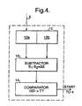
- Figure 4 illustrates an arrangement used for giving a continuously variable threshold level which may be used in place of the comparator 7 of Figure 1.
- the signal S on line 5 derived from the CCD output is applied to a storage means 12 having two sections 12a and 12b.
- the current signal magnitude is stored in part 12a of the store and the previous value is shifted to part 12b.
- the two signal magnitudes are subtracted at 13 to give a difference showing the change in magnitude of the signal over the time between the two samples. This is compared with a fixed threshold value T at comparator 14.
- the level T is set at a value which is greater than would be expected for changes between the two signal values due solely to thermal effects and other changes in ambient conditions but is significantly smaller than a change which would occur on the onset of irradiation with X-rays.
- the output of the comparator 14 is applied to the control unit 4 to begin image acquisition when the onset of X-ray irradiation is detected.
- the threshold value T is fixed, the signal which is compared with it is continually varied in accordance with changes due thermal effects and other noise considerations and thus the conditions of the threshold test are variable with changes in the ambient conditions.
Landscapes
- Health & Medical Sciences (AREA)
- Life Sciences & Earth Sciences (AREA)
- Engineering & Computer Science (AREA)
- Signal Processing (AREA)
- Medical Informatics (AREA)
- High Energy & Nuclear Physics (AREA)
- Molecular Biology (AREA)
- Physics & Mathematics (AREA)
- Multimedia (AREA)
- Biophysics (AREA)
- Biomedical Technology (AREA)
- Oral & Maxillofacial Surgery (AREA)
- Spectroscopy & Molecular Physics (AREA)
- General Physics & Mathematics (AREA)
- Nuclear Medicine, Radiotherapy & Molecular Imaging (AREA)
- Optics & Photonics (AREA)
- Pathology (AREA)
- Radiology & Medical Imaging (AREA)
- Dentistry (AREA)
- Heart & Thoracic Surgery (AREA)
- Surgery (AREA)
- Animal Behavior & Ethology (AREA)
- General Health & Medical Sciences (AREA)
- Public Health (AREA)
- Veterinary Medicine (AREA)
- Apparatus For Radiation Diagnosis (AREA)
- Measurement Of Radiation (AREA)
Description
- This invention relates to imaging apparatus and more particularly to solid state imagers which include radiation sensitive detector elements.
- It has been proposed to use CCDs and other types of solid state detectors for dental and other medical applications using X-ray irradiation to examine structural features of a patient. The CCD device replaces the film used in previous systems and enables real-time imaging to be achieved together with a more controlled lower dosage of X-rays for a given exposure.
- In one known arrangement, a CCD device is used intra-orally and is electrically connected to an X-ray source. When the X-ray source is energised, a start signal is transmitted along the connecting wire to the CCD device and to its control circuitry to begin image acquisition and read-out. In other arrangements, the X-ray source and CCD device have no physical connection. A supplementary sensor is arranged close to the imaging area of the CCD to detect the onset of X-ray energy. On detection of the incident X-ray energy, the sensor sends a signal to the CCD control circuitry to cause imaging to begin.
- In another arrangement, the CCD device is continually read-out prior to irradiation by X-rays. A signal derived from the CCD is compared with a reference level. If it exceeds the reference level, the image acquisition phase of the CCD operation is initiated.
-
WO 93/23952 -
WO 92/22188 - The present invention seeks to provide an improved imaging apparatus which is particularly advantageously used for dental X-ray diagnosis where the imager device is located intra-orally but it is envisaged that it may also be used in other medical or diagnostic applications and could also be advantageously employed for non-medical applications.
- The invention is defined in the claims to which reference is directed.
- Solid state devices such as CCDs suffer from the generation of a thermally based signal known as dark current. During a wait period, for example, in an X-ray system before X-ray exposure, the imager device generates dark current which uses signal handling capacity of the device and may even totally fill that capacity leaving no space for signal information. When onset of X-rays begins therefore, the device must be emptied of the charge it holds due to noise to enable image acquisition to be initiated.
- Dark current approximately doubles every 7° C in silicon devices and in dental use, CCDs may be used with an operating temperature of up to 40°C. In the previously known arrangement in which the signal output is compared with a reference level, it is therefore necessary to set this reference at a relatively high level to allow for signals arising from 40°C dark current and other noise features. This is significant given the exponential rise in dark current with temperature. If the reference is set too low, a false trigger signal may result causing a failed image and requiring the patient to be subjected to a repeat exposure.
- By employing the invention, a threshold test is used which may be continually varied to accommodate changes in ambient conditions. Hence, the threshold level need not be set initially at a high level unless ambient conditions so require. Immediately prior to a particular X-ray exposure, the CCD may subjected to a temperature of only 20°C, say, and not 40° C which may be encountered after some time or not at all although in theory this temperature might be attained. As the level is minimised to that required for the particular conditions encountered the onset of X-ray radiation is more quickly and reliably determined than in the previously known system. Hence the dosage of X-ray radiation to which the patient is subjected is also minimized as image acquisition is started nearer the beginning of the X-ray pulse. A rapid change in the signal derived from the detector elements indicates the onset of the radiation to be imaged and causes image acquisition to be begin. The signal may be derived directly from the detector elements or may be processed in some way first.
- The invention is particularly advantageously used for X-ray irradiation of patients for dental and other medical uses such as mammography as it allows X-ray dosages to be reduced to the minimum level required. This meets stringent health and safety requirements by avoiding unnecessary exposure to X-ray radiation which is not used in the production of an image without increasing the risk of image failure with the need to repeat the procedure.
- Although the invention is particularly useful for dental applications because of the temperature constraints, other medical applications may also with advantage employ it. Also, the invention may be employed, for example, in non-X-ray imaging arrangements such as where optical radiation is to be monitored or for other types of high energy radiation.
- The change in the threshold condition in most cases will occur because of variations in the ambient temperature. However, in some applications, ambient background illumination may be monitored and the threshold varied accordingly. A further benefit of the invention is that the threshold will also be varied to take into account the increase in dark current which occurs in solid state imagers when exposed to ionising radiation such as X-rays.
- In one particularly advantageous embodiment of the invention , a signal derived from the detector elements is compared with a previously derived signal to give a difference over a known short time interval and the difference is compared with a set threshold level. Although in this case, the threshold level is set at a fixed value, the comparison to determine the difference in previous and current signals is used to compensate for changes in temperature and hence changes the threshold condition.
- Some ways in which the invention may be performed are now described with reference to the accompanying drawings in which:
- Figure 1 schematically illustrates an X-ray imaging arrangement for intra-oral dental use;
- Figure 2 schematically shows in greater detail part of the arrangement shown in Figure 1;
- Figure 3 is an explanatory diagram relating to the operation of the arrangement of Figure 1; and
- Figure 4 shows part of an arrangement in accordance with the invention.
- With reference to Figure 1, an
X-ray source 1 is arranged to irradiate a tooth orother object 2 to be imaged behind which is located aCCD sensor device 3. TheCCD device 3 comprises an array of radiation sensitive detector elements which accumulate charge depending on the intensity of the radiation which is incident thereon. By applying control signals from acontrol unit 4 the accumulated charge can be clocked from the sensor elements at selected times to produce a signal S on anoutput line 5 which is representative of the radiation pattern falling on thedetector 3. In the absence of radiation, the signal S will essentially be due to dark current and other noise. - The signal S is applied to
signal processing circuit 6 and to acomparator 7. Thecomparator 7 performs a comparison test to determine if there is a rapid change in the magnitude of the signal, which indicates that theX-ray source 1 has been switched on. When this occurs, a start signal is transmitted alongoutput line 8 to thecontrol unit 4 to begin image acquisition by thedevice 3. Prior to the irradiation with the X-ray source, thecontrol unit 4 applies potentials to the CCD electrodes to continually clock out the charge accumulating at the sensor elements online 5. Thecomparator 7 is also connected to apply a signal thesignal processor 6 to enable it to accept the signal information for image processing when the test indicates that the X-ray source is irradiating theobject 2. - Figure 2 illustrates part of the
signal processor 6 in more detail. The signal S online 5 is first applied to a low pass filter 9 with a long time constant. This removes any short term fluctuations from the signal, including the effect of the X-ray pulse, and provides a signal which tracks the long term average of signal S as ambient conditions vary. - A positive offset (Vo) is then applied to the low pass filtered signal by an offset circuit 10 to generate a reference signal which is then passed to the
comparator 7. - Under normal conditions the output of the
comparator 7 will be low due to the offset voltage Vo. However, when an X-ray pulse is applied, signal S will rise rapidly. The action of the low pass filter 9 prevents the reference signal from rising quickly and hence the output of the comparator will switch high indicating that image acquisition should begin. - The
comparator 7 continues receiving a signal online 5 during image acquisition and also detects when the X-ray source is switched off at the end of the irradiation period. - Figure 3 is an explanatory diagram which illustrates the operation of the arrangement of Figure 1. The time consent of the filter 9 is chosen to be significantly greater than the duration Tx of the transmitted X-ray pulse.
- Figure 4 illustrates an arrangement used for giving a continuously variable threshold level which may be used in place of the
comparator 7 of Figure 1. In this arrangement, the signal S online 5 derived from the CCD output is applied to a storage means 12 having twosections part 12a of the store and the previous value is shifted topart 12b. The two signal magnitudes are subtracted at 13 to give a difference showing the change in magnitude of the signal over the time between the two samples. This is compared with a fixed threshold value T atcomparator 14. The level T is set at a value which is greater than would be expected for changes between the two signal values due solely to thermal effects and other changes in ambient conditions but is significantly smaller than a change which would occur on the onset of irradiation with X-rays. The output of thecomparator 14 is applied to thecontrol unit 4 to begin image acquisition when the onset of X-ray irradiation is detected. In this case, therefore, although the threshold value T is fixed, the signal which is compared with it is continually varied in accordance with changes due thermal effects and other noise considerations and thus the conditions of the threshold test are variable with changes in the ambient conditions.
Claims (7)
- Imaging apparatus comprising: a solid state imager device (3) including radiation sensitive detector elements; means (14) for comparing a signal derived from the detector elements with a threshold level to carry out the threshold test; means for varying a threshold condition of the threshold test in accordance with changes in ambient conditions; and means (6) for initiating image acquisition by said imager device when said threshold test is satisfied; wherein the means for varying a threshold condition includes comparison means (13, 14) for comparing a signal (S) derived from the detector elements with a previously obtained signal from the detector elements to give a difference which is compared with a threshold level.
- Apparatus as claimed in any preceding claim wherein the solid state device is a CCD device (3).
- Apparatus as claimed in any preceding claim wherein the apparatus is adapted for use in an intraoral arrangement.
- Apparatus as claimed in any preceding claim wherein the imager device is used to detect X-ray radiation.
- Apparatus as claimed in any preceding claim and including an X-ray source (1) for irradiating a subject behind which the solid state imager device (3) is located during use.
- Apparatus as claimed in any preceding claim and including means (4) for substantially continually clocking out charge from the detector elements prior to initiating image acquisition.
- A dental X-ray imaging apparatus comprising; an X-ray source (1); a solid state imager device (3) for receiving X-ray radiation from the source after it has passed through a subject (2); means (4) for initiating image acquisition when a threshold test is satisfied which includes means for comparing (6,7,14) a signal derived from the imager device (3) with a threshold condition; and means (9, 13) for varying the threshold condition in accordance with changes in ambient conditions; wherein the means for varying a threshold condition includes comparison means (13, 14) for comparing a signal (S) derived from the detector elements with a previously obtained signal from the detector elements to give a difference which is compared with a threshold level.
Applications Claiming Priority (2)
| Application Number | Priority Date | Filing Date | Title |
|---|---|---|---|
| GB9515762 | 1995-08-01 | ||
| GBGB9515762.4A GB9515762D0 (en) | 1995-08-01 | 1995-08-01 | Imaging apparatus |
Publications (3)
| Publication Number | Publication Date |
|---|---|
| EP0757474A1 EP0757474A1 (en) | 1997-02-05 |
| EP0757474B1 EP0757474B1 (en) | 2001-12-12 |
| EP0757474B2 true EP0757474B2 (en) | 2007-07-18 |
Family
ID=10778593
Family Applications (1)
| Application Number | Title | Priority Date | Filing Date |
|---|---|---|---|
| EP96305131A Expired - Lifetime EP0757474B2 (en) | 1995-08-01 | 1996-07-12 | Imaging apparatus |
Country Status (6)
| Country | Link |
|---|---|
| US (1) | US5694448A (en) |
| EP (1) | EP0757474B2 (en) |
| JP (1) | JP4111559B2 (en) |
| DE (1) | DE69617828T3 (en) |
| GB (1) | GB9515762D0 (en) |
| RU (1) | RU2153233C2 (en) |
Families Citing this family (34)
| Publication number | Priority date | Publication date | Assignee | Title |
|---|---|---|---|---|
| US5912942A (en) * | 1997-06-06 | 1999-06-15 | Schick Technologies, Inc. | X-ray detection system using active pixel sensors |
| US6149300A (en) * | 1997-10-17 | 2000-11-21 | Welch Allyn, Inc. | Intraoral imaging system |
| DE60031787T2 (en) | 1999-10-08 | 2007-02-22 | Gendex Corp. | AUTOMATIC EXPOSURE CONTROL FOR A DENTAL PANORAMIC AND CERPHALOGRAPHIC X-RAY EQUIPMENT |
| AU782164B2 (en) | 2000-02-02 | 2005-07-07 | Gendex Corporation | Automatic x-ray detection for intra-oral dental x-ray imaging apparatus |
| US6404854B1 (en) | 2000-06-26 | 2002-06-11 | Afp Imaging Corporation | Dental x-ray imaging system |
| US6307915B1 (en) | 2000-06-26 | 2001-10-23 | Afp Imaging Corporation | Triggering of solid state X-ray imagers with non-destructive readout capability |
| US6891926B1 (en) | 2000-08-09 | 2005-05-10 | Dalsa, Inc. | Fiber bundles for x-ray imaging |
| US7016461B2 (en) | 2001-07-25 | 2006-03-21 | Gendex Corporation | Real-time digital x-ray imaging apparatus |
| FI117818B (en) * | 2001-08-03 | 2007-03-15 | Palodex Group Oy | Radiation regulation in an X-ray imaging device used for an intraoral application |
| US6677569B2 (en) | 2001-10-12 | 2004-01-13 | Massachusetts Institute Of Technology | Methods and apparatus for performing signal processing functions in an electronic imager |
| US6794630B2 (en) * | 2001-12-17 | 2004-09-21 | Intel Corporation | Method and apparatus for adjusting the threshold of a CMOS radiation-measuring circuit |
| WO2004014232A1 (en) | 2002-07-25 | 2004-02-19 | Gendex Corporation | Real-time digital x-ray imaging apparatus and method |
| US7006600B1 (en) | 2004-01-15 | 2006-02-28 | Progeny, Inc. | Integrated digital dental x-ray system |
| US7848595B2 (en) | 2004-06-28 | 2010-12-07 | Inphase Technologies, Inc. | Processing data pixels in a holographic data storage system |
| ATE346546T1 (en) * | 2004-08-06 | 2006-12-15 | Gendex Corp | IMAGE SENSOR FOR DENTAL INTRAORAL X-RAY RADIOGRAPHY |
| ITBO20040638A1 (en) | 2004-10-15 | 2005-01-15 | Elca Technologies S R L | EQUIPMENT FOR THE ACQUISITION AND VISUALIZATION OF DENTAL RADIOGRAPHIC IMAGES AND ITS FUNCTIONING METHOD |
| FR2881640B1 (en) * | 2005-02-09 | 2007-05-11 | Sopro Sa | OPTIMIZATION OF THE X-RAY QUANTITY RECEIVED BY A PATIENT IN A DENTAL RADIOLOGICAL IMAGE ACQUISITION SYSTEM |
| JP2006246961A (en) * | 2005-03-08 | 2006-09-21 | Hamamatsu Photonics Kk | X-ray imaging device |
| GB0514998D0 (en) * | 2005-07-21 | 2005-08-31 | E2V Tech Uk Ltd | Sensor with trigger pixels for imaging of pulsed radiation |
| JP5105940B2 (en) * | 2007-04-06 | 2012-12-26 | キヤノン株式会社 | Imaging apparatus, imaging system, control method thereof, and program |
| IL201765A (en) * | 2008-10-27 | 2013-06-27 | Imaging Sciences Int Llc | System and method of x-ray detection with a sensor |
| US8366318B2 (en) | 2009-07-17 | 2013-02-05 | Dental Imaging Technologies Corporation | Intraoral X-ray sensor with embedded standard computer interface |
| US9492129B2 (en) * | 2008-10-27 | 2016-11-15 | Dental Imaging Technologies Corporation | Triggering of intraoral X-ray sensor using pixel array sub-sampling |
| JP2012083307A (en) * | 2010-10-14 | 2012-04-26 | Fujifilm Corp | Radiation detection device, radiation image photographing system, radiation detection program and radiation detection method |
| JP2012118312A (en) * | 2010-12-01 | 2012-06-21 | Fujifilm Corp | Radiation image detector and drive control method thereof |
| FR2977977B1 (en) * | 2011-07-13 | 2013-08-30 | Trixell | METHOD FOR CONTROLLING A PHOTOSENSITIVE DETECTOR BY AUTOMATIC DETECTION OF INCIDENT RADIATION |
| CA2853109C (en) | 2011-10-24 | 2019-02-26 | Helmholtz Zentrum Munchen Deutsches Forschungszentrum Fur Gesundheit Und Umwelt (Gmbh) | Method for measuring radiation by means of an electronic terminal having a digital camera |
| JP5988735B2 (en) * | 2012-07-06 | 2016-09-07 | キヤノン株式会社 | Radiation imaging apparatus control method, radiation imaging apparatus, and radiation imaging system |
| JP5986443B2 (en) * | 2012-07-13 | 2016-09-06 | 富士フイルム株式会社 | Radiographic imaging apparatus, control method and program for detecting sensitivity at start of radiation irradiation |
| JP6577700B2 (en) | 2014-06-30 | 2019-09-18 | キヤノン株式会社 | Radiation detection apparatus, control method therefor, radiation imaging apparatus, and program |
| FR3032105B1 (en) * | 2015-01-30 | 2017-01-27 | E2V Semiconductors | RADIOLOGICAL SENSOR WITH DETECTION OF X-RAYS |
| JP6366542B2 (en) * | 2015-06-17 | 2018-08-01 | キヤノン株式会社 | Radiation imaging apparatus, radiation imaging system, and irradiation start detection method |
| KR101930402B1 (en) | 2017-04-17 | 2018-12-18 | 서울대학교산학협력단 | Apparatus and method for signal sampling based on time using sawtooth shaped threshold |
| CN108322680B (en) * | 2018-01-18 | 2020-06-09 | 昆山晔芯电子科技有限公司 | Temperature self-adaptive black level calibration method and system of image sensor |
Citations (3)
| Publication number | Priority date | Publication date | Assignee | Title |
|---|---|---|---|---|
| WO1992022188A1 (en) † | 1991-06-03 | 1992-12-10 | Regam Medical Systems Ab | Method and device for triggering of x-ray image sensor |
| WO1993025059A1 (en) † | 1992-06-01 | 1993-12-09 | Siemens Aktiengesellschaft | Dental x-ray diagnostic device |
| DE3925589C2 (en) † | 1989-08-02 | 1994-03-17 | Blaupunkt Werke Gmbh | Method and arrangement for the elimination of interference from speech signals |
Family Cites Families (6)
| Publication number | Priority date | Publication date | Assignee | Title |
|---|---|---|---|---|
| SU907868A1 (en) * | 1980-04-21 | 1982-02-23 | Научно-Исследовательский Институт Электронной Интроскопии При Томском Ордена Октябрьской Революции И Ордена Трудового Красного Знамени Политехническом Институте Им.С.М.Кирова | Device for compensating for differencies in sensitivity of photodetector matrix elements |
| JPS5772113A (en) * | 1980-10-23 | 1982-05-06 | Canon Inc | Signal processing system |
| JPH02101878A (en) * | 1988-10-11 | 1990-04-13 | Nec Corp | Solid-state image pickup device |
| DE8909398U1 (en) * | 1989-08-03 | 1989-10-05 | Siemens AG, 1000 Berlin und 8000 München | Dental X-ray diagnostic facility |
| SE9201482L (en) * | 1992-05-11 | 1993-11-12 | Regam Medical Systems Ab | Method for compensating dark current at CCd sensor for dental x-ray |
| RU2040862C1 (en) * | 1993-02-02 | 1995-07-25 | Научно-исследовательский институт промышленного телевидения "Растр" | Television analyzer having matrix of charge-coupling units |
-
1995
- 1995-08-01 GB GBGB9515762.4A patent/GB9515762D0/en active Pending
-
1996
- 1996-07-12 EP EP96305131A patent/EP0757474B2/en not_active Expired - Lifetime
- 1996-07-12 US US08/679,517 patent/US5694448A/en not_active Expired - Lifetime
- 1996-07-12 DE DE69617828T patent/DE69617828T3/en not_active Expired - Lifetime
- 1996-07-31 JP JP20225696A patent/JP4111559B2/en not_active Expired - Lifetime
- 1996-07-31 RU RU96115384/09A patent/RU2153233C2/en not_active IP Right Cessation
Patent Citations (3)
| Publication number | Priority date | Publication date | Assignee | Title |
|---|---|---|---|---|
| DE3925589C2 (en) † | 1989-08-02 | 1994-03-17 | Blaupunkt Werke Gmbh | Method and arrangement for the elimination of interference from speech signals |
| WO1992022188A1 (en) † | 1991-06-03 | 1992-12-10 | Regam Medical Systems Ab | Method and device for triggering of x-ray image sensor |
| WO1993025059A1 (en) † | 1992-06-01 | 1993-12-09 | Siemens Aktiengesellschaft | Dental x-ray diagnostic device |
Non-Patent Citations (5)
| Title |
|---|
| Digitale Regelsysteme - Bd. II, Rolf Isermann, 1987, 2. Ed. Pages 145,146 and 341,342 † |
| Elektronische Messtechnik, Jürgen Winfried Klein, 1992, Pages 100-107, Chapter 3.6 Triggerschaltungen für Amplituden- und Zeitsignifikanz † |
| Grundkurs der Regelungstechnik, Ludwig Merz, 1964,2. Ed. Pages A/12-A/15 † |
| Halbleiter-Schaltungstechnik, Tietze Schenk, 1980, 5. Ed., Pages 200-205 and 288 till 291 † |
| Usermanual - TDS 544A Digitizing Oscilloscopes from Tektronix, March 1993, particularly Triggermodes and-types, Pages 2-13 till 2-18, 3-22 till 3-36, 3-59 till 3-64, 3-100 till 3-106 and 3-122 till 3-126 † |
Also Published As
| Publication number | Publication date |
|---|---|
| JP4111559B2 (en) | 2008-07-02 |
| GB9515762D0 (en) | 1995-10-04 |
| US5694448A (en) | 1997-12-02 |
| EP0757474B1 (en) | 2001-12-12 |
| EP0757474A1 (en) | 1997-02-05 |
| DE69617828D1 (en) | 2002-01-24 |
| DE69617828T2 (en) | 2002-04-04 |
| JPH09133772A (en) | 1997-05-20 |
| DE69617828T3 (en) | 2008-01-24 |
| RU2153233C2 (en) | 2000-07-20 |
Similar Documents
| Publication | Publication Date | Title |
|---|---|---|
| EP0757474B2 (en) | Imaging apparatus | |
| EP0756416B1 (en) | Imaging apparatus | |
| JP3068191B2 (en) | Dental X-ray diagnostic equipment | |
| EP2180343B1 (en) | System and method of x-ray detection with a sensor | |
| US20170049410A1 (en) | Triggering of intraoral x-ray sensor using pixel array sub-sampling | |
| US6307915B1 (en) | Triggering of solid state X-ray imagers with non-destructive readout capability | |
| US8953742B2 (en) | Radiation image detecting device and method for controlling the same | |
| EP1252762B1 (en) | Automatic x-ray detection for intra-oral dental x-ray imaging apparatus | |
| US8431905B2 (en) | Radiation image detector | |
| JP2005205221A (en) | Image shooting device | |
| CN102525506A (en) | Radiographic image detection equipment and its control method | |
| RU96115384A (en) | IMAGE FORMING DEVICE | |
| GB2304017A (en) | Imaging apparatus | |
| WO2002052504A2 (en) | Method and system for dual energy radiographic imaging employing a digital detector | |
| CN1156376A (en) | Image forming apparatus | |
| JP2005114667A (en) | Signal detection method and device | |
| JPH09508480A (en) | Image pickup device | |
| JP4574336B2 (en) | X-ray equipment | |
| US20040131155A1 (en) | X-ray diagnostic system with a CCD camera |
Legal Events
| Date | Code | Title | Description |
|---|---|---|---|
| PUAI | Public reference made under article 153(3) epc to a published international application that has entered the european phase |
Free format text: ORIGINAL CODE: 0009012 |
|
| AK | Designated contracting states |
Kind code of ref document: A1 Designated state(s): DE FI FR IT SE |
|
| 17P | Request for examination filed |
Effective date: 19970730 |
|
| 17Q | First examination report despatched |
Effective date: 19991021 |
|
| GRAG | Despatch of communication of intention to grant |
Free format text: ORIGINAL CODE: EPIDOS AGRA |
|
| GRAG | Despatch of communication of intention to grant |
Free format text: ORIGINAL CODE: EPIDOS AGRA |
|
| GRAG | Despatch of communication of intention to grant |
Free format text: ORIGINAL CODE: EPIDOS AGRA |
|
| GRAH | Despatch of communication of intention to grant a patent |
Free format text: ORIGINAL CODE: EPIDOS IGRA |
|
| RAP1 | Party data changed (applicant data changed or rights of an application transferred) |
Owner name: MARCONI APPLIED TECHNOLOGIES LIMITED |
|
| GRAH | Despatch of communication of intention to grant a patent |
Free format text: ORIGINAL CODE: EPIDOS IGRA |
|
| GRAA | (expected) grant |
Free format text: ORIGINAL CODE: 0009210 |
|
| AK | Designated contracting states |
Kind code of ref document: B1 Designated state(s): DE FI FR IT SE |
|
| REF | Corresponds to: |
Ref document number: 69617828 Country of ref document: DE Date of ref document: 20020124 |
|
| ET | Fr: translation filed | ||
| PLBQ | Unpublished change to opponent data |
Free format text: ORIGINAL CODE: EPIDOS OPPO |
|
| PLBQ | Unpublished change to opponent data |
Free format text: ORIGINAL CODE: EPIDOS OPPO |
|
| PLBI | Opposition filed |
Free format text: ORIGINAL CODE: 0009260 |
|
| PLBF | Reply of patent proprietor to notice(s) of opposition |
Free format text: ORIGINAL CODE: EPIDOS OBSO |
|
| 26 | Opposition filed |
Opponent name: SIRONA DENTAL SYSTEMS GMBH Effective date: 20020911 |
|
| PLBF | Reply of patent proprietor to notice(s) of opposition |
Free format text: ORIGINAL CODE: EPIDOS OBSO |
|
| PLBQ | Unpublished change to opponent data |
Free format text: ORIGINAL CODE: EPIDOS OPPO |
|
| PLAB | Opposition data, opponent's data or that of the opponent's representative modified |
Free format text: ORIGINAL CODE: 0009299OPPO |
|
| PLBF | Reply of patent proprietor to notice(s) of opposition |
Free format text: ORIGINAL CODE: EPIDOS OBSO |
|
| R26 | Opposition filed (corrected) |
Opponent name: SIRONA DENTAL SYSTEMS GMBH Effective date: 20020911 |
|
| RAP2 | Party data changed (patent owner data changed or rights of a patent transferred) |
Owner name: E2V TECHNOLOGIES (UK) LIMITED |
|
| REG | Reference to a national code |
Ref country code: FR Ref legal event code: CD |
|
| PUAH | Patent maintained in amended form |
Free format text: ORIGINAL CODE: 0009272 |
|
| STAA | Information on the status of an ep patent application or granted ep patent |
Free format text: STATUS: PATENT MAINTAINED AS AMENDED |
|
| 27A | Patent maintained in amended form |
Effective date: 20070718 |
|
| AK | Designated contracting states |
Kind code of ref document: B2 Designated state(s): DE FI FR IT SE |
|
| REG | Reference to a national code |
Ref country code: SE Ref legal event code: RPEO |
|
| ET3 | Fr: translation filed ** decision concerning opposition | ||
| PGFP | Annual fee paid to national office [announced via postgrant information from national office to epo] |
Ref country code: SE Payment date: 20100708 Year of fee payment: 15 Ref country code: IT Payment date: 20100724 Year of fee payment: 15 Ref country code: FI Payment date: 20100712 Year of fee payment: 15 |
|
| REG | Reference to a national code |
Ref country code: SE Ref legal event code: EUG |
|
| PG25 | Lapsed in a contracting state [announced via postgrant information from national office to epo] |
Ref country code: IT Free format text: LAPSE BECAUSE OF NON-PAYMENT OF DUE FEES Effective date: 20110712 Ref country code: FI Free format text: LAPSE BECAUSE OF NON-PAYMENT OF DUE FEES Effective date: 20110712 |
|
| PG25 | Lapsed in a contracting state [announced via postgrant information from national office to epo] |
Ref country code: SE Free format text: LAPSE BECAUSE OF NON-PAYMENT OF DUE FEES Effective date: 20110713 |
|
| REG | Reference to a national code |
Ref country code: FR Ref legal event code: PLFP Year of fee payment: 20 |
|
| PGFP | Annual fee paid to national office [announced via postgrant information from national office to epo] |
Ref country code: DE Payment date: 20150707 Year of fee payment: 20 |
|
| PGFP | Annual fee paid to national office [announced via postgrant information from national office to epo] |
Ref country code: FR Payment date: 20150629 Year of fee payment: 20 |
|
| REG | Reference to a national code |
Ref country code: DE Ref legal event code: R071 Ref document number: 69617828 Country of ref document: DE |