EP0756977B1 - Schalldämpfer für Luftabsperrhähne - Google Patents
Schalldämpfer für Luftabsperrhähne Download PDFInfo
- Publication number
- EP0756977B1 EP0756977B1 EP96109689A EP96109689A EP0756977B1 EP 0756977 B1 EP0756977 B1 EP 0756977B1 EP 96109689 A EP96109689 A EP 96109689A EP 96109689 A EP96109689 A EP 96109689A EP 0756977 B1 EP0756977 B1 EP 0756977B1
- Authority
- EP
- European Patent Office
- Prior art keywords
- ring
- silencer
- valve
- air
- flow channels
- Prior art date
- Legal status (The legal status is an assumption and is not a legal conclusion. Google has not performed a legal analysis and makes no representation as to the accuracy of the status listed.)
- Expired - Lifetime
Links
Images
Classifications
-
- F—MECHANICAL ENGINEERING; LIGHTING; HEATING; WEAPONS; BLASTING
- F01—MACHINES OR ENGINES IN GENERAL; ENGINE PLANTS IN GENERAL; STEAM ENGINES
- F01N—GAS-FLOW SILENCERS OR EXHAUST APPARATUS FOR MACHINES OR ENGINES IN GENERAL; GAS-FLOW SILENCERS OR EXHAUST APPARATUS FOR INTERNAL-COMBUSTION ENGINES
- F01N1/00—Silencing apparatus characterised by method of silencing
- F01N1/08—Silencing apparatus characterised by method of silencing by reducing exhaust energy by throttling or whirling
- F01N1/082—Silencing apparatus characterised by method of silencing by reducing exhaust energy by throttling or whirling by passing the exhaust gases through porous members
-
- B—PERFORMING OPERATIONS; TRANSPORTING
- B60—VEHICLES IN GENERAL
- B60T—VEHICLE BRAKE CONTROL SYSTEMS OR PARTS THEREOF; BRAKE CONTROL SYSTEMS OR PARTS THEREOF, IN GENERAL; ARRANGEMENT OF BRAKING ELEMENTS ON VEHICLES IN GENERAL; PORTABLE DEVICES FOR PREVENTING UNWANTED MOVEMENT OF VEHICLES; VEHICLE MODIFICATIONS TO FACILITATE COOLING OF BRAKES
- B60T17/00—Component parts, details, or accessories of power brake systems not covered by groups B60T8/00, B60T13/00 or B60T15/00, or presenting other characteristic features
- B60T17/002—Air treatment devices
- B60T17/008—Silencer devices
-
- F—MECHANICAL ENGINEERING; LIGHTING; HEATING; WEAPONS; BLASTING
- F01—MACHINES OR ENGINES IN GENERAL; ENGINE PLANTS IN GENERAL; STEAM ENGINES
- F01N—GAS-FLOW SILENCERS OR EXHAUST APPARATUS FOR MACHINES OR ENGINES IN GENERAL; GAS-FLOW SILENCERS OR EXHAUST APPARATUS FOR INTERNAL-COMBUSTION ENGINES
- F01N2330/00—Structure of catalyst support or particle filter
- F01N2330/14—Sintered material
Definitions
- the invention relates to a silencer for Air shut-off valves in the air lines of rail vehicles.
- the air brakes of individual rail vehicles in the Train sets are via flexible, couplable brake couplings connected with each other. Before each brake clutch is one Air shut-off valve arranged.
- the UIC code stipulates a cross-section of at least 80 mm 2 for ventilation. At the same time, the boundary lines for the air shut-off valves specify a very small installation space.
- the vent screws the air shut-off valves in compliance with the above Boundary lines trained accordingly.
- Vent screws are known, which separate the airflow into two Divide the parts and divert them by 180 °. Are further Vent screws known to the vent hole arrange several smaller holes and thus the air flow partly split several times into several smaller air flows.
- a silencer is suitable for air shut-off valves, especially of vehicles, and suitable to be arranged on the air shut-off valve to be known, being in a housing, transverse to a vent hole, the opens into a deflection space, several flow channels are arranged, which be enclosed by a damping ring.
- the invention has for its object to develop a solution that ensures the greatest possible sound attenuation while maintaining a minimum cross-section of 80 mm 2 and compliance with the boundary lines according to UIC 542.
- the object is achieved by the arrangement of a silencer on the air shut-off valve with the in claim described features solved.
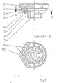
- FIG 1 shows the configuration of the invention Silencer.
- Deflection space 2 is provided around which, transverse to the bore 1, a plurality of preferably four, flow channels 3 arranged in a star shape are. These are enclosed by a damping ring 4 which made of sound-absorbing material, preferably sintered Plastic is made and in its position to the Flow channels 3 through, arranged in the housing 10 Guide ribs 6 is secured.
- Annular gaps 5 are provided between the guide ribs 6, which open into an annular space 7, the one with the free atmosphere communicates.
- a perforated ring 9, preferably made of sound absorbing material, with holes 8 can be arranged on the annular space 7.
- the noise generated in the flow channels 3 impacts the Damping ring 4 and is largely absorbed by this.
- the air flows around the damping ring 4 and passes through the Annular gap 5 between the guide ribs 6 of the housing 10 in the annulus 7. Part of the air passes through the porous Damping ring 4 directly into the annular space 7.
Landscapes
- Engineering & Computer Science (AREA)
- Mechanical Engineering (AREA)
- Combustion & Propulsion (AREA)
- General Engineering & Computer Science (AREA)
- Transportation (AREA)
- Chemical & Material Sciences (AREA)
- Details Of Valves (AREA)
- Self-Closing Valves And Venting Or Aerating Valves (AREA)
- Exhaust Silencers (AREA)
- Fluid-Damping Devices (AREA)
- Cooling, Air Intake And Gas Exhaust, And Fuel Tank Arrangements In Propulsion Units (AREA)
- Compressor (AREA)
- Control Of Throttle Valves Provided In The Intake System Or In The Exhaust System (AREA)
- Check Valves (AREA)
Description
- 1
- Bohrung
- 2
- Umlenkraum
- 3
- Strömungskanäle
- 4
- Dämpfring
- 5
- Ringspalt
- 6
- Führungsrippen
- 7
- Ringraum
- 8
- Bohrung
- 9
- Lochring
- 10
- Gehäuse
Claims (3)
- Schalldämpfer für Luftabsperrhähne, insbesondere von Fahrzeugen, und geeignet, um an einem Luftabsperrhahn angeordnet zu werden, wobei in einem Gehäuse (10), quer zu einer Entlüftungsbohrung (1), die in einem Umlenkraum (2) mündet, mehrere Strömungskanäle (3) angeordnet sind, die durch einen Dämpfring (4) umschlossen werden, dadurch gekennzeichnet, daß im Gehäuse (10) vorzugsweise vier Strömungskanäle (3) angeordnet sind, und der Dämpfring (4) in seiner Lage zu den Strömungskanälen (3) durch Führungsrippen (6) gesichert ist, wobei zwischen den Führungsrippen (6) Ringspalten (5) vorgesehen sind, die in einen Ringraum (7) münden, der mit der Atmosphäre Verbindung hat.
- Schalldämpfer nach Anspruch 1, gekennzeichnet dadurch, daß die Verbindung zur Atmosphäre durch einen Lochring (9) mit Bohrungen (8) gebildet wird.
- Schalldämpfer nach den Ansprüchen 1 und 2, gekennzeichnet dadurch, daß der Dämpfring (4) und/oder der Lochring (9) aus schallabsorbierendem Material besteht.
Applications Claiming Priority (2)
| Application Number | Priority Date | Filing Date | Title |
|---|---|---|---|
| DE19528006 | 1995-07-31 | ||
| DE19528006A DE19528006C2 (de) | 1995-07-31 | 1995-07-31 | Schalldämpfer für Luftabsperrhähne |
Publications (3)
| Publication Number | Publication Date |
|---|---|
| EP0756977A2 EP0756977A2 (de) | 1997-02-05 |
| EP0756977A3 EP0756977A3 (de) | 1998-07-22 |
| EP0756977B1 true EP0756977B1 (de) | 2001-09-05 |
Family
ID=7768262
Family Applications (1)
| Application Number | Title | Priority Date | Filing Date |
|---|---|---|---|
| EP96109689A Expired - Lifetime EP0756977B1 (de) | 1995-07-31 | 1996-06-17 | Schalldämpfer für Luftabsperrhähne |
Country Status (3)
| Country | Link |
|---|---|
| EP (1) | EP0756977B1 (de) |
| AT (1) | ATE205144T1 (de) |
| DE (2) | DE19528006C2 (de) |
Family Cites Families (5)
| Publication number | Priority date | Publication date | Assignee | Title |
|---|---|---|---|---|
| DE511919C (de) * | 1930-11-04 | Aeg | Schalldaempfer fuer Brennkraftmaschinen | |
| US2065343A (en) * | 1930-11-13 | 1936-12-22 | M & M Engineering Corp | Exhaust muffler |
| US3208551A (en) * | 1963-11-18 | 1965-09-28 | Carls William | Combined air muffler and metering valve with replaceable cartridge |
| DE3327902A1 (de) * | 1983-08-02 | 1985-02-14 | Knorr-Bremse GmbH, 8000 München | Geraeuschdaempfer fuer ventilanordnungen in druckluftanlagen, insbesondere in druckluftbremsanlagen von fahrzeugen |
| JPS6185520A (ja) * | 1984-10-03 | 1986-05-01 | Fumihiro Nakagawa | 消音器 |
-
1995
- 1995-07-31 DE DE19528006A patent/DE19528006C2/de not_active Expired - Fee Related
-
1996
- 1996-06-17 AT AT96109689T patent/ATE205144T1/de not_active IP Right Cessation
- 1996-06-17 DE DE59607617T patent/DE59607617D1/de not_active Expired - Fee Related
- 1996-06-17 EP EP96109689A patent/EP0756977B1/de not_active Expired - Lifetime
Also Published As
| Publication number | Publication date |
|---|---|
| EP0756977A3 (de) | 1998-07-22 |
| EP0756977A2 (de) | 1997-02-05 |
| DE59607617D1 (de) | 2001-10-11 |
| DE19528006A1 (de) | 1997-02-06 |
| ATE205144T1 (de) | 2001-09-15 |
| DE19528006C2 (de) | 1997-08-14 |
Similar Documents
| Publication | Publication Date | Title |
|---|---|---|
| EP3687872B1 (de) | Geräuschdämpfer für druckluftsysteme und ein verfahren zu dessen herstellung | |
| DE2922677C2 (de) | Geräuschdämpfer für Ventileinrichtungen in Druckluftbremsanlagen | |
| DE102019204907A1 (de) | Getriebe für ein Nutzfahrzeug mit einem Getriebegehäuse mit Entlüftungsanordnung | |
| EP0123843B1 (de) | Lufttrockner | |
| EP0596220B1 (de) | Druckluft-Entlüftungseinrichtung | |
| DE3001486A1 (de) | Kombinierte schalldaempfer-oelabscheidevorrichtung | |
| DE4212228C2 (de) | Hydraulischer Schwingungsdämpfer für Kraftfahrzeuge | |
| DE102014215563A1 (de) | Dämpfventil | |
| WO2019170364A1 (de) | Fahrzeug mit einer klimaanordnung | |
| DE3332677A1 (de) | Reifendruckregelanlage | |
| DE102011014273A1 (de) | Bremseinrichtung eines Schienenfahrzeugs mit in Neutralposition federbelasteter Bremszangeneinheit | |
| DE102021117390A1 (de) | Arbeitsmediumtank für einen hydrodynamischen Retarder | |
| EP0756977B1 (de) | Schalldämpfer für Luftabsperrhähne | |
| DE3327902A1 (de) | Geraeuschdaempfer fuer ventilanordnungen in druckluftanlagen, insbesondere in druckluftbremsanlagen von fahrzeugen | |
| EP0359945B1 (de) | Druckluft-Entlüftungseinrichtung | |
| DE4331966A1 (de) | Steuereinrichtung | |
| DE3240710C2 (de) | Entlüftungsschalldämpfer | |
| DE19845196B4 (de) | Zwangsentlüftungsvorrichtung | |
| DE2929610C2 (de) | Rückschlagventil | |
| EP0379160B1 (de) | Schalldämpfer | |
| AT892U1 (de) | Scheibenbremse, insbesondere für schienenfahrzeuge | |
| DE102008015763B4 (de) | Vorrichtung zur Be-/Entlüftung einer Mehrzahl von pneumatischen Aktuatoren, Sitz und Fahrzeug mit einer derartigen Vorrichtung | |
| DE10157284A1 (de) | Bremsscheibe aus Faserverbundwerkstoff | |
| EP0084598A1 (de) | Schalldämpfer, insbesondere für Druckluftgeräte | |
| DE102020200730B3 (de) | Dämpfventil für einen Schwingungsdämpfer |
Legal Events
| Date | Code | Title | Description |
|---|---|---|---|
| PUAI | Public reference made under article 153(3) epc to a published international application that has entered the european phase |
Free format text: ORIGINAL CODE: 0009012 |
|
| AK | Designated contracting states |
Kind code of ref document: A2 Designated state(s): AT BE CH DE FR GB LI NL SE |
|
| PUAL | Search report despatched |
Free format text: ORIGINAL CODE: 0009013 |
|
| AK | Designated contracting states |
Kind code of ref document: A3 Designated state(s): AT BE CH DE FR GB LI NL SE |
|
| 17P | Request for examination filed |
Effective date: 19980929 |
|
| 17Q | First examination report despatched |
Effective date: 20000210 |
|
| GRAG | Despatch of communication of intention to grant |
Free format text: ORIGINAL CODE: EPIDOS AGRA |
|
| GRAG | Despatch of communication of intention to grant |
Free format text: ORIGINAL CODE: EPIDOS AGRA |
|
| GRAH | Despatch of communication of intention to grant a patent |
Free format text: ORIGINAL CODE: EPIDOS IGRA |
|
| GRAH | Despatch of communication of intention to grant a patent |
Free format text: ORIGINAL CODE: EPIDOS IGRA |
|
| GRAA | (expected) grant |
Free format text: ORIGINAL CODE: 0009210 |
|
| AK | Designated contracting states |
Kind code of ref document: B1 Designated state(s): AT BE CH DE FR GB LI NL SE |
|
| REF | Corresponds to: |
Ref document number: 205144 Country of ref document: AT Date of ref document: 20010915 Kind code of ref document: T |
|
| REG | Reference to a national code |
Ref country code: CH Ref legal event code: NV Representative=s name: ISLER & PEDRAZZINI AG Ref country code: CH Ref legal event code: EP |
|
| GBT | Gb: translation of ep patent filed (gb section 77(6)(a)/1977) |
Effective date: 20010905 |
|
| REF | Corresponds to: |
Ref document number: 59607617 Country of ref document: DE Date of ref document: 20011011 |
|
| REG | Reference to a national code |
Ref country code: GB Ref legal event code: IF02 |
|
| ET | Fr: translation filed | ||
| PLBE | No opposition filed within time limit |
Free format text: ORIGINAL CODE: 0009261 |
|
| STAA | Information on the status of an ep patent application or granted ep patent |
Free format text: STATUS: NO OPPOSITION FILED WITHIN TIME LIMIT |
|
| 26N | No opposition filed | ||
| REG | Reference to a national code |
Ref country code: CH Ref legal event code: PCAR Free format text: ISLER & PEDRAZZINI AG;POSTFACH 1772;8027 ZUERICH (CH) |
|
| PGFP | Annual fee paid to national office [announced via postgrant information from national office to epo] |
Ref country code: CH Payment date: 20080624 Year of fee payment: 13 |
|
| PGFP | Annual fee paid to national office [announced via postgrant information from national office to epo] |
Ref country code: AT Payment date: 20080620 Year of fee payment: 13 |
|
| PGFP | Annual fee paid to national office [announced via postgrant information from national office to epo] |
Ref country code: BE Payment date: 20080623 Year of fee payment: 13 |
|
| PGFP | Annual fee paid to national office [announced via postgrant information from national office to epo] |
Ref country code: NL Payment date: 20080618 Year of fee payment: 13 Ref country code: DE Payment date: 20080827 Year of fee payment: 13 Ref country code: SE Payment date: 20080624 Year of fee payment: 13 |
|
| PGFP | Annual fee paid to national office [announced via postgrant information from national office to epo] |
Ref country code: FR Payment date: 20080618 Year of fee payment: 13 |
|
| PGFP | Annual fee paid to national office [announced via postgrant information from national office to epo] |
Ref country code: GB Payment date: 20080624 Year of fee payment: 13 |
|
| BERE | Be: lapsed |
Owner name: *KNORR-BREMSE SYSTEME FUR SCHIENENFAHRZEUGE G.M.B. Effective date: 20090630 |
|
| REG | Reference to a national code |
Ref country code: CH Ref legal event code: PL |
|
| GBPC | Gb: european patent ceased through non-payment of renewal fee |
Effective date: 20090617 |
|
| NLV4 | Nl: lapsed or anulled due to non-payment of the annual fee |
Effective date: 20100101 |
|
| REG | Reference to a national code |
Ref country code: FR Ref legal event code: ST Effective date: 20100226 |
|
| PG25 | Lapsed in a contracting state [announced via postgrant information from national office to epo] |
Ref country code: LI Free format text: LAPSE BECAUSE OF NON-PAYMENT OF DUE FEES Effective date: 20090630 Ref country code: FR Free format text: LAPSE BECAUSE OF NON-PAYMENT OF DUE FEES Effective date: 20090630 Ref country code: CH Free format text: LAPSE BECAUSE OF NON-PAYMENT OF DUE FEES Effective date: 20090630 |
|
| PG25 | Lapsed in a contracting state [announced via postgrant information from national office to epo] |
Ref country code: GB Free format text: LAPSE BECAUSE OF NON-PAYMENT OF DUE FEES Effective date: 20090617 |
|
| PG25 | Lapsed in a contracting state [announced via postgrant information from national office to epo] |
Ref country code: DE Free format text: LAPSE BECAUSE OF NON-PAYMENT OF DUE FEES Effective date: 20100101 Ref country code: BE Free format text: LAPSE BECAUSE OF NON-PAYMENT OF DUE FEES Effective date: 20090630 Ref country code: AT Free format text: LAPSE BECAUSE OF NON-PAYMENT OF DUE FEES Effective date: 20090617 |
|
| PG25 | Lapsed in a contracting state [announced via postgrant information from national office to epo] |
Ref country code: NL Free format text: LAPSE BECAUSE OF NON-PAYMENT OF DUE FEES Effective date: 20100101 |
|
| PG25 | Lapsed in a contracting state [announced via postgrant information from national office to epo] |
Ref country code: SE Free format text: LAPSE BECAUSE OF NON-PAYMENT OF DUE FEES Effective date: 20090618 |