EP0756937B1 - Verbindungsstruktur für Druckkopfbefestigung und Farbstoffpatronen - Google Patents
Verbindungsstruktur für Druckkopfbefestigung und Farbstoffpatronen Download PDFInfo
- Publication number
- EP0756937B1 EP0756937B1 EP96305641A EP96305641A EP0756937B1 EP 0756937 B1 EP0756937 B1 EP 0756937B1 EP 96305641 A EP96305641 A EP 96305641A EP 96305641 A EP96305641 A EP 96305641A EP 0756937 B1 EP0756937 B1 EP 0756937B1
- Authority
- EP
- European Patent Office
- Prior art keywords
- ink
- cartridge
- ink cartridge
- section
- connecting structure
- Prior art date
- Legal status (The legal status is an assumption and is not a legal conclusion. Google has not performed a legal analysis and makes no representation as to the accuracy of the status listed.)
- Expired - Lifetime
Links
- 238000005192 partition Methods 0.000 claims description 22
- 238000003780 insertion Methods 0.000 claims description 12
- 230000037431 insertion Effects 0.000 claims description 12
- 239000012535 impurity Substances 0.000 claims description 2
- 238000003466 welding Methods 0.000 description 8
- 230000002093 peripheral effect Effects 0.000 description 4
- 239000003086 colorant Substances 0.000 description 2
- 238000012986 modification Methods 0.000 description 2
- 230000004048 modification Effects 0.000 description 2
- 230000002745 absorbent Effects 0.000 description 1
- 239000002250 absorbent Substances 0.000 description 1
- 238000010276 construction Methods 0.000 description 1
- 239000000428 dust Substances 0.000 description 1
- 238000004519 manufacturing process Methods 0.000 description 1
- 239000000463 material Substances 0.000 description 1
- 230000002265 prevention Effects 0.000 description 1
- 238000000638 solvent extraction Methods 0.000 description 1
Images


Classifications
-
- B—PERFORMING OPERATIONS; TRANSPORTING
- B41—PRINTING; LINING MACHINES; TYPEWRITERS; STAMPS
- B41J—TYPEWRITERS; SELECTIVE PRINTING MECHANISMS, i.e. MECHANISMS PRINTING OTHERWISE THAN FROM A FORME; CORRECTION OF TYPOGRAPHICAL ERRORS
- B41J2/00—Typewriters or selective printing mechanisms characterised by the printing or marking process for which they are designed
- B41J2/005—Typewriters or selective printing mechanisms characterised by the printing or marking process for which they are designed characterised by bringing liquid or particles selectively into contact with a printing material
- B41J2/01—Ink jet
- B41J2/17—Ink jet characterised by ink handling
- B41J2/175—Ink supply systems ; Circuit parts therefor
- B41J2/17503—Ink cartridges
- B41J2/1752—Mounting within the printer
Definitions
- the invention achieves other objects by providing a connecting structure of a head holder and an ink cartridge, which is able to prevent damage to the filter of the ink supply member that supplies the ink to the ink jet head from the ink cartridge mounted in the head holder with the ink jet head connected to the ink cartridge, even when the ink cartridge is mounted in a wrong direction. Further, damage is prevented when the ink cartridge is mounted upside down in the head holder.
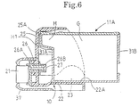
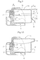
- Fig. 6 is a schematic explanatory view illustrating a cartridge mounted in a wrong direction in a mounting sections 22A-22D
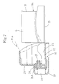
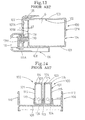
- Fig. 7 is a schematic explanatory view of a cartridge 11A, being mounted upside down from the front side to the cartridge mounting sections
- Fig. 8 is a schematic explanatory view of a cartridge 11A being mounted upside down from the rear side to the cartridge mounting sections 22A-22D.
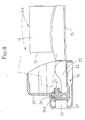
- the ink supply member 26 attached on the head holder 10 is inserted in the insertion hole 33 of the cartridge 11A and presses the ink-impregnated body G to force the ink out.
- the ink is supplied to the ink jet head 21 through the ink hole 26A.
- the ink supply member 26 will be positioned in a space defined by the grip section H and the rear surface 31A of the ink container 31, shown in Fig. 6. Accordingly, the mesh filter 27 does not abut the wall surface, for example the rear surface 31A of the ink container 31.
Landscapes
- Ink Jet (AREA)
Claims (14)
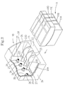
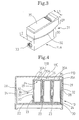
- Verbindungsaufbau mit:einem Kopfhalter (10) mit:einer Vorderwand (25) ;einer Bodenwand (22); undeinem Tintenlieferteil (26) zum Liefern von Tinte zu einem Tintenstrahlkopf, das nach innen von einer inneren Oberfläche der Vorderwand (25) um einen Vorsprungsabstand eines Tintenlieferteiles vorsteht; undeinem Patronenanbringungsabschnitt (22A, B, C, D), der in der Bodenwand (22) gebildet ist;einer in dem Patronenanbringungsabschnitt anzubringenden Tintenpatrone (11) mit einer im wesentlichen rechteckigen Form, wobei die Tintenpatrone (11) aufweist:ein in einer vorderen Oberfläche der Tintenpatronen (11) gebildetes Einführungsloch (33), das der inneren Oberfläche der Vorderwand (25) des Kopfhalters (10) zugewandt ist, wobei das Einführungsloch (33) dem Tintenlieferteil ermöglicht, mit dem Inneren der Patrone in Verbindung zu stehen; undeinen Vorsprungsabschnitt (29), der von einer hinteren Oberfläche der Tintenpatrone (11) gegenüber der vorderen Oberfläche um einen Vorsprungsabstand eines Vorsprungsabschnittes an einer Höhe unterschiedlich von einer Höhe des Tintenlieferteiles nach außen vorsteht;wobei der Vorsprungsabstand des Vorsprungsabschnittes größer als der Vorsprungsabstand des Tintenlieferteiles ist.
- Verbindungsaufbau nach Anspruch 1, bei dem der Kopfhalter mindestens eine Trennwand (23) zum Positionieren einer Tintenpatrone (11), wobei die Trennwand (23) in Kontakt mit einem Abschnitt der Tintenpatrone steht, und eine Tintenpatrone mit einer Breite kleiner an dem Abschnitt in Kontakt mit der Trennwand als an anderen Abschnitten der Tintenpatrone aufweist.
- Verbindungsaufbau nach Anspruch 1 oder 2, weiter mit:
einem an einem Ende des Tintenlieferteiles (26) angebrachten Filter (27). - Verbindungsaufbau nach Anspruch 3, bei dem das Filter ein Siebfilter (27) zum Entfernen von Verunreinigungen aus der Tinte innerhalb der Tintenpatrone ist.
- Verbindungsaufbau nach einem der Ansprüche 1 bis 4, bei dem der Vorsprungsabschnitt (29) einen Griffabschnitt (H) aufweist, der nach außen von einem Innenteil der hinteren Oberfläche der Tintenpatrone (11) vorsteht, worin der Griffabschnitt eine Bodenkante aufweist, eine erste Höhe, die von einer oberen Oberfläche der Bodenwand des Kopfhalters (10) zu der Bodenkante des Griffabschnittes definiert ist, größer als eine zweite Höhe ist, die von der oberen Oberfläche der Bodenwand zu der oberen Kante des Tintenlieferteiles definiert ist.
- Verbindungsaufbau nach einem der vorhergehenden Ansprüche, bei dem die Tintenpatrone (11) einen oberen Abschnitt (29) mit einer ersten Breite (L1) und einen unteren Abschnitt (30) mit einer zweiten Breite (L2) unterschiedlich zu der ersten Breite aufweist.
- Verbindungsaufbau nach Anspruch 6, bei dem die Tintenpatrone weiter einen gestuften Abschnitt aufweist, der den oberen von dem unteren Abschnitt trennt.
- Verbindungsaufbau nach Anspruch 6 oder 7, bei dem die erste Breite (L1) größer als die zweite Breite (L2) ist.
- Verbindungsaufbau nach Anspruch 6, 7 oder 8, bei dem der Kopfhalter eine Mehrzahl von Trennwänden (23) zum Positionieren dazwischen mindestens einer Tintenpatrone aufweist, wobei jeweils eine benachbarte Trennwand um eine Breite getrennt ist, die im wesentlichen gleich der zweiten Breite des unteren Abschnittes (29) der Tintenpatrone (11) ist.
- Verbindungsaufbau nach einem der vorhergehenden Ansprüche, bei dem die Tintenpatrone (11) zum Kontakt mit Trennwänden (23) des Kopfhalters (10) und zum Positionieren dazwischen dient und eine Breite kleiner an dem Abschnitt in Kontakt mit den Trennwänden als an anderen Abschnitten aufweist.
- Verbindungsaufbau nach einem der vorhergehenden Ansprüche, bei dem die Tintenpatrone weiter eine getrennte Abdeckung aufweist, die mit der Tintenpatrone verbunden ist.
- Verbindungsaufbau nach einem der vorhergehenden Ansprüche, bei dem der vorstehende Abschnitt nach außen von einem oberen Abschnitt der hinteren Oberfläche der Tintenpatrone vorsteht.
- Verbindungsaufbau nach einem der Ansprüche 1 bis 12, bei dem der vorstehende Abschnitt (40) nach außen von einem unteren Abschnitt der hinteren Oberfläche der Tintenpatrone vorsteht.
- Verbindungsaufbau nach einem der vorhergehenden Ansprüche, bei dem die Tintenpatrone einen tintenimprägnierten Körper enthält.
Applications Claiming Priority (3)
| Application Number | Priority Date | Filing Date | Title |
|---|---|---|---|
| JP21667095 | 1995-08-01 | ||
| JP216670/95 | 1995-08-01 | ||
| JP21667095A JP3479392B2 (ja) | 1995-08-01 | 1995-08-01 | インクカートリッジの連結構造 |
Publications (3)
| Publication Number | Publication Date |
|---|---|
| EP0756937A2 EP0756937A2 (de) | 1997-02-05 |
| EP0756937A3 EP0756937A3 (de) | 1998-06-10 |
| EP0756937B1 true EP0756937B1 (de) | 2001-10-24 |
Family
ID=16692091
Family Applications (1)
| Application Number | Title | Priority Date | Filing Date |
|---|---|---|---|
| EP96305641A Expired - Lifetime EP0756937B1 (de) | 1995-08-01 | 1996-07-31 | Verbindungsstruktur für Druckkopfbefestigung und Farbstoffpatronen |
Country Status (6)
| Country | Link |
|---|---|
| US (1) | US5949457A (de) |
| EP (1) | EP0756937B1 (de) |
| JP (1) | JP3479392B2 (de) |
| CN (1) | CN1143017A (de) |
| AU (1) | AU713690B2 (de) |
| DE (1) | DE69616202T2 (de) |
Families Citing this family (4)
| Publication number | Priority date | Publication date | Assignee | Title |
|---|---|---|---|---|
| US6188417B1 (en) | 1994-10-31 | 2001-02-13 | Hewlett-Packard Company | Fluidic adapter for use with an inkjet print cartridge having an internal pressure regulator |
| US6273560B1 (en) * | 1994-10-31 | 2001-08-14 | Hewlett-Packard Company | Print cartridge coupling and reservoir assembly for use in an inkjet printing system with an off-axis ink supply |
| US6779874B2 (en) * | 2001-07-31 | 2004-08-24 | Hewlett-Packard Development Company, Lp. | Device for ensuring proper toe-heel installation of a detachable printer component |
| CN109318596B (zh) * | 2017-07-31 | 2021-04-30 | 兄弟工业株式会社 | 液体消耗装置及液体消耗系统 |
Family Cites Families (13)
| Publication number | Priority date | Publication date | Assignee | Title |
|---|---|---|---|---|
| DE299360C (de) * | ||||
| DE2543991C3 (de) * | 1975-10-02 | 1980-04-10 | Olympia Werke Ag, 2940 Wilhelmshaven | Tintenvorratsbehälter für Tintenschreiber |
| US4593294A (en) * | 1985-04-22 | 1986-06-03 | Exxon Printing Systems, Inc. | Ink jet method and apparatus |
| JPS6357243A (ja) * | 1986-08-28 | 1988-03-11 | Toshiba Corp | 記録装置 |
| IT1232551B (it) * | 1989-07-13 | 1992-02-19 | Olivetti & Co Spa | Testina di stampa per una stampante termica a getto d'inchiostro |
| US5488401A (en) * | 1991-01-18 | 1996-01-30 | Seiko Epson Corporation | Ink-jet recording apparatus and ink tank cartridge thereof |
| CA2084708C (en) * | 1991-12-11 | 1997-11-25 | Hiromitsu Hirabayashi | Ink jet recording apparatus and carriage mechanism therefor |
| JP2962044B2 (ja) * | 1992-05-29 | 1999-10-12 | 富士ゼロックス株式会社 | インクタンク、インクジェットカートリッジ、及びインクジェット記録装置 |
| US5509140A (en) * | 1992-07-24 | 1996-04-16 | Canon Kabushiki Kaisha | Replaceable ink cartridge |
| CA2101017C (en) * | 1992-07-24 | 1999-10-26 | Masahiko Higuma | Ink jet cartridge, ink jet head and printer |
| JP3133906B2 (ja) * | 1993-08-19 | 2001-02-13 | キヤノン株式会社 | インクタンクカートリッジ |
| US5619239A (en) * | 1993-11-29 | 1997-04-08 | Canon Kabushiki Kaisha | Replaceable ink tank |
| JP3280202B2 (ja) * | 1995-08-01 | 2002-04-30 | ブラザー工業株式会社 | インクジェットプリンタ |
-
1995
- 1995-08-01 JP JP21667095A patent/JP3479392B2/ja not_active Expired - Lifetime
-
1996
- 1996-04-26 US US08/638,564 patent/US5949457A/en not_active Expired - Lifetime
- 1996-07-31 DE DE69616202T patent/DE69616202T2/de not_active Expired - Lifetime
- 1996-07-31 AU AU60846/96A patent/AU713690B2/en not_active Ceased
- 1996-07-31 EP EP96305641A patent/EP0756937B1/de not_active Expired - Lifetime
- 1996-08-01 CN CN96111788.5A patent/CN1143017A/zh active Pending
Also Published As
| Publication number | Publication date |
|---|---|
| AU713690B2 (en) | 1999-12-09 |
| JPH0939267A (ja) | 1997-02-10 |
| DE69616202T2 (de) | 2002-04-18 |
| US5949457A (en) | 1999-09-07 |
| AU6084696A (en) | 1997-02-06 |
| EP0756937A2 (de) | 1997-02-05 |
| EP0756937A3 (de) | 1998-06-10 |
| DE69616202D1 (de) | 2001-11-29 |
| JP3479392B2 (ja) | 2003-12-15 |
| CN1143017A (zh) | 1997-02-19 |
Similar Documents
| Publication | Publication Date | Title |
|---|---|---|
| US5534899A (en) | Replaceable ink tank | |
| US6070975A (en) | Ink jet recording apparatus and a method for installing ink jet recording head | |
| US5604523A (en) | Ink container, an ink jet cartridge and ink jet recording apparatus | |
| JP3745161B2 (ja) | 液体収納容器 | |
| EP1219445B1 (de) | Tintenpatrone | |
| KR20020068465A (ko) | 잉크젯 헤드 및 잉크젯 프린터 | |
| US12521993B2 (en) | Liquid container | |
| EP1832428B1 (de) | Flüssigkeitsausstossvorrichtung mit Flüssigkeitsverteilervorrichtung | |
| EP0756937B1 (de) | Verbindungsstruktur für Druckkopfbefestigung und Farbstoffpatronen | |
| US6120128A (en) | Container for safekeeping ink cartridge | |
| JP3873502B2 (ja) | インクジェット記録装置 | |
| US5872578A (en) | Capping device for ink jet head in ink jet printer | |
| US9561663B2 (en) | Ink cartridge and printer | |
| JPH07179004A (ja) | インクジェットヘッドカートリッジおよびインクジェット記録装置 | |
| JP7135602B2 (ja) | タンク及び液体消費装置 | |
| US20240217240A1 (en) | Inkjet printer | |
| US11179954B2 (en) | Printer | |
| JPH07304190A (ja) | 液体噴射記録装置 | |
| WO2025100299A1 (ja) | 液体容器 | |
| AU2002301858B2 (en) | Ink Tank, Ink Jet Head Cartridge, and Ink Jet Recording Apparatus | |
| JP2007111864A (ja) | 記録液カートリッジ及び画像形成装置 | |
| JP2004122460A (ja) | インクタンクホルダ |
Legal Events
| Date | Code | Title | Description |
|---|---|---|---|
| PUAI | Public reference made under article 153(3) epc to a published international application that has entered the european phase |
Free format text: ORIGINAL CODE: 0009012 |
|
| AK | Designated contracting states |
Kind code of ref document: A2 Designated state(s): CH DE FR GB LI |
|
| PUAL | Search report despatched |
Free format text: ORIGINAL CODE: 0009013 |
|
| AK | Designated contracting states |
Kind code of ref document: A3 Designated state(s): CH DE FR GB LI |
|
| 17P | Request for examination filed |
Effective date: 19980806 |
|
| 17Q | First examination report despatched |
Effective date: 19990624 |
|
| GRAG | Despatch of communication of intention to grant |
Free format text: ORIGINAL CODE: EPIDOS AGRA |
|
| GRAG | Despatch of communication of intention to grant |
Free format text: ORIGINAL CODE: EPIDOS AGRA |
|
| GRAH | Despatch of communication of intention to grant a patent |
Free format text: ORIGINAL CODE: EPIDOS IGRA |
|
| GRAH | Despatch of communication of intention to grant a patent |
Free format text: ORIGINAL CODE: EPIDOS IGRA |
|
| GRAA | (expected) grant |
Free format text: ORIGINAL CODE: 0009210 |
|
| AK | Designated contracting states |
Kind code of ref document: B1 Designated state(s): CH DE FR GB LI |
|
| PG25 | Lapsed in a contracting state [announced via postgrant information from national office to epo] |
Ref country code: LI Free format text: LAPSE BECAUSE OF FAILURE TO SUBMIT A TRANSLATION OF THE DESCRIPTION OR TO PAY THE FEE WITHIN THE PRESCRIBED TIME-LIMIT Effective date: 20011024 Ref country code: CH Free format text: LAPSE BECAUSE OF FAILURE TO SUBMIT A TRANSLATION OF THE DESCRIPTION OR TO PAY THE FEE WITHIN THE PRESCRIBED TIME-LIMIT Effective date: 20011024 |
|
| REG | Reference to a national code |
Ref country code: CH Ref legal event code: EP |
|
| REF | Corresponds to: |
Ref document number: 69616202 Country of ref document: DE Date of ref document: 20011129 |
|
| ET | Fr: translation filed | ||
| REG | Reference to a national code |
Ref country code: GB Ref legal event code: IF02 |
|
| REG | Reference to a national code |
Ref country code: CH Ref legal event code: PL |
|
| PLBE | No opposition filed within time limit |
Free format text: ORIGINAL CODE: 0009261 |
|
| STAA | Information on the status of an ep patent application or granted ep patent |
Free format text: STATUS: NO OPPOSITION FILED WITHIN TIME LIMIT |
|
| 26N | No opposition filed | ||
| REG | Reference to a national code |
Ref country code: FR Ref legal event code: PLFP Year of fee payment: 20 |
|
| PGFP | Annual fee paid to national office [announced via postgrant information from national office to epo] |
Ref country code: GB Payment date: 20150624 Year of fee payment: 20 |
|
| PGFP | Annual fee paid to national office [announced via postgrant information from national office to epo] |
Ref country code: FR Payment date: 20150624 Year of fee payment: 20 |
|
| PGFP | Annual fee paid to national office [announced via postgrant information from national office to epo] |
Ref country code: DE Payment date: 20150731 Year of fee payment: 20 |
|
| REG | Reference to a national code |
Ref country code: DE Ref legal event code: R071 Ref document number: 69616202 Country of ref document: DE |
|
| REG | Reference to a national code |
Ref country code: GB Ref legal event code: PE20 Expiry date: 20160730 |
|
| PG25 | Lapsed in a contracting state [announced via postgrant information from national office to epo] |
Ref country code: GB Free format text: LAPSE BECAUSE OF EXPIRATION OF PROTECTION Effective date: 20160730 |