EP0756937B1 - Connecting structure for printing head and ink cartridge - Google Patents
Connecting structure for printing head and ink cartridge Download PDFInfo
- Publication number
- EP0756937B1 EP0756937B1 EP96305641A EP96305641A EP0756937B1 EP 0756937 B1 EP0756937 B1 EP 0756937B1 EP 96305641 A EP96305641 A EP 96305641A EP 96305641 A EP96305641 A EP 96305641A EP 0756937 B1 EP0756937 B1 EP 0756937B1
- Authority
- EP
- European Patent Office
- Prior art keywords
- ink
- cartridge
- ink cartridge
- section
- connecting structure
- Prior art date
- Legal status (The legal status is an assumption and is not a legal conclusion. Google has not performed a legal analysis and makes no representation as to the accuracy of the status listed.)
- Expired - Lifetime
Links
- 238000005192 partition Methods 0.000 claims description 22
- 238000003780 insertion Methods 0.000 claims description 12
- 230000037431 insertion Effects 0.000 claims description 12
- 239000012535 impurity Substances 0.000 claims description 2
- 238000003466 welding Methods 0.000 description 8
- 230000002093 peripheral effect Effects 0.000 description 4
- 239000003086 colorant Substances 0.000 description 2
- 238000012986 modification Methods 0.000 description 2
- 230000004048 modification Effects 0.000 description 2
- 230000002745 absorbent Effects 0.000 description 1
- 239000002250 absorbent Substances 0.000 description 1
- 238000010276 construction Methods 0.000 description 1
- 239000000428 dust Substances 0.000 description 1
- 238000004519 manufacturing process Methods 0.000 description 1
- 239000000463 material Substances 0.000 description 1
- 230000002265 prevention Effects 0.000 description 1
- 238000000638 solvent extraction Methods 0.000 description 1
Images


Classifications
-
- B—PERFORMING OPERATIONS; TRANSPORTING
- B41—PRINTING; LINING MACHINES; TYPEWRITERS; STAMPS
- B41J—TYPEWRITERS; SELECTIVE PRINTING MECHANISMS, i.e. MECHANISMS PRINTING OTHERWISE THAN FROM A FORME; CORRECTION OF TYPOGRAPHICAL ERRORS
- B41J2/00—Typewriters or selective printing mechanisms characterised by the printing or marking process for which they are designed
- B41J2/005—Typewriters or selective printing mechanisms characterised by the printing or marking process for which they are designed characterised by bringing liquid or particles selectively into contact with a printing material
- B41J2/01—Ink jet
- B41J2/17—Ink jet characterised by ink handling
- B41J2/175—Ink supply systems ; Circuit parts therefor
- B41J2/17503—Ink cartridges
- B41J2/1752—Mounting within the printer
Definitions
- the invention achieves other objects by providing a connecting structure of a head holder and an ink cartridge, which is able to prevent damage to the filter of the ink supply member that supplies the ink to the ink jet head from the ink cartridge mounted in the head holder with the ink jet head connected to the ink cartridge, even when the ink cartridge is mounted in a wrong direction. Further, damage is prevented when the ink cartridge is mounted upside down in the head holder.
- Fig. 6 is a schematic explanatory view illustrating a cartridge mounted in a wrong direction in a mounting sections 22A-22D
- Fig. 7 is a schematic explanatory view of a cartridge 11A, being mounted upside down from the front side to the cartridge mounting sections
- Fig. 8 is a schematic explanatory view of a cartridge 11A being mounted upside down from the rear side to the cartridge mounting sections 22A-22D.
- the ink supply member 26 attached on the head holder 10 is inserted in the insertion hole 33 of the cartridge 11A and presses the ink-impregnated body G to force the ink out.
- the ink is supplied to the ink jet head 21 through the ink hole 26A.
- the ink supply member 26 will be positioned in a space defined by the grip section H and the rear surface 31A of the ink container 31, shown in Fig. 6. Accordingly, the mesh filter 27 does not abut the wall surface, for example the rear surface 31A of the ink container 31.
Landscapes
- Ink Jet (AREA)
Description
- The present invention relates to a cooperating connecting structure of a head holder and an ink cartridge for connecting the head holder attached on an ink jet printer for mounting an ink jet head to an ink cartridge. The ink cartridge is removably mounted on the head holder and supplies ink to the ink jet head. In particular, the invention relates to a connecting structure of a head holder and an ink cartridge that reliably prevents damage to an ink filter of an ink supply member mounted on the head holder, if the ink cartridge is mounted in a wrong direction or upside down. The ink supply member connects the ink jet head to the ink cartridge and supplies the ink from the ink cartridge to the ink jet head.
- There have been various kinds of known ink cartridges for use in ink jet printers. In an ink jet printer capable of printing in colors, for example, black, magneta, yellow and cyan, four separate ink cartridges are generally mounted in the head holder.
- EP-A-0655336 describes an ink container comprising a plurality of ink storing portion for storing one of a plurality of types of ink to be supplied to a color recording head; wherein the interal space of the ink container is divided with a substantially T-shaped partitioning wall so that at least three types of ink can be stored.
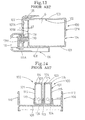
- An ink cartridge used in another type of ink jet printer will be explained below, with reference to Fig. 12. Fig. 12 is a longitudinal sectional view of the
ink cartridge 100. In Fig. 12, theink cartridge 100 is formed in an approximately rectangular parallel piped configuration. Theink cartridge 100 comprises anink container 101 in which an ink-impregnated body G is incorporated. Acartridge cover 103 is joined, for example by welding, to the peripheral edge of theupper opening 102 in theink container 101. Beneath thefront surface 101A (left side in Fig. 12) of theink container 101, aninsertion hole 104 is formed. An ink supply member 109 (described later) is inserted into thisinsertion hole 104 and is attached to ahead holder 106 when theink cartridge 100 is mounted on thehead holder 106. At the rear part of the cartridge cover 103 (right side in Fig. 12), agrip section 105 is formed. Thisgrip section 105 permits gripping of theink cartridge 100 when theink cartridge 100 is mounted to, and removed from, thehead holder 106. - The
grip section 105 is disposed above therear surface 101B (right side surface in Fig. 12) of theink container 101. The distance of outward protrusion of the grip section from therear surface 101B is a1 as shown in Fig. 12. - The
ink cartridge 100 of the above-described structure will not pose mounting problems, so long as it is mounted to thehead holder 106 in a proper position and relation to thehead holder 106. - The
ink cartridge 100, however, is generally small in size, and therefore it is conceivable that theink cartridge 100 can be improperly mounted. For example, theink cartridge 100 can be mounted from a wrong direction or upside down onto thehead holder 106. Such improper mounting will be explained with reference to Figs. 13 and 14. Fig. 13 is a longitudinal sectional view showing theink cartridge 100 mounted in a wrong direction on thehead holder 106. Fig. 14 is a cross sectional view of theink cartridge 100 mounted on thehead holder 106. - First, the structure of the
head holder 106 will be explained. In Fig. 13, thehead holder 106 has afront wall 107 and an integrally formedbottom wall 108. In thefront wall 107, anink supply member 109 comprises anink hole 109A, which corresponds to theinsertion hole 104 when theink cartridge 100 is properly mounted on thebottom wall 108. At the front end of the ink supply member 109 (right end in Fig. 13), amesh filter 110 is installed. Themesh filter 110 serves to remove impurities, such as dust in the ink, when the ink is supplied from the ink-impregnated body G in theink cartridge 100 to theink jet head 111. - The inward protrusion distance of the
ink supply member 109 from theinner surface 107A of thefront wall 107 is a2. The protrusion distance a2 is greater than the protrusion distance a1 of thegrip section 105, which is formed on theink cartridge 100. Theink jet head 111 is mounted to thehead holder 106 on the front side of thefront wall 107, and ahead cover 111A is disposed around it. - The
head holder 106, as shown in Fig. 14, has a pair ofside walls 112, and a plurality of partition walls, or example three partition walls as shown in Fig. 14, formed on thebottom wall 108 between theside walls 112. Anink cartridge 100 is mounted between each pair ofpartition walls 113. - The peripheral edge of the
ink cartridge 100, an opening 101 of theink container 100 and thecartridge cover 103 are generally joined to each other, for example, by ultrasonic welding. In particular, the surfaces of theink container 101 and thecartridge cover 104 are welded by shear welding for a substantial amount of weld strength. Also, an outside portion ofprotrusion 114, which is formed on the underside of thecartridge cover 103, and an inside step section of the peripheral edge of the opening, which is formed in theink container 101, are joined, for example by welding, as shown in Fig. 14. Therefore, with shear welding, the peripheral edge of the opening of theink container 101 should be at least 1.5 mm thick. To meet this requirement, a pair ofopposite side walls 115 in theink container 101 of aconventional ink cartridge 100, are 1.5 mm thick throughout. The whole body of theink cartridge 100, has the substantially same vertical width. - If the
above ink cartridge 100 is mounted in an incorrect direction between theside wall 112 and thepartition wall 113 in thebottom wall 108 of thehead holder 106, therear surface 101B of theink container 101 faces themesh filter 110 of theink supply member 109, as shown in Fig. 13. At this time, the protrusion distance a2 of theink supply member 109 extending inward from theinner surface 107A of theside wall 107 is greater than the protrusion distance a1 of thegrip section 105 formed on theink cartridge 100. Therefore, themesh filter 110 of theink supply member 109 contacts therear surface 101B of theink container 101, consequently damaging themesh filter 110. - The
ink cartridge 100, which is formed with the same width in the vertical direction, can be mounted between theside wall 112 and thepartition wall 113, even if mounted upside down in thehead holder 106. However, if theink cartridge 100 is mounted upside down, themesh filter 110 of theink supply member 109 contacts therear surface 101B of theink container 101, and for the same reasons stated above, results in a damagedmesh filter 110. Furthermore, if theink cartridge 100 is mounted upside down on thehead holder 106, themesh filter 110 of theink supply member 109 will immediately contact thefront surface 101A of theink container 101, because thegrip section 105 is not present on thefront surface 101A. In this case, themesh filter 110 is also likely to be damaged. - Therefore, if the
ink cartridge 100 is mounted in a wrong direction or upside down on thehead holder 106, themesh filter 110 mounted on the forward end of theink supply member 109 will be damaged. - According to the present invention, there is provided a connecting structure comprising a head holder having:
- a front wall;
- a bottom wall; and
- an ink supply member for supplying ink to an ink jet head and protruding inwardly from an inner surface of said front wall by an ink supply member protrusion distance; and
- a cartridge mounting section formed in said bottom wall;
- an ink cartridge to be mounted in said cartridge mounting section and having a
substantially rectangular shape, the ink cartridge having:
- an insertion hole formed in a front surface of said ink cartridge and for facing the inner surface of said front wall of said head holder, the insertion hole allowing said ink supply member to communicate with interior of the cartridge; and
- a protruding section protruding outwardly from a rear surface of said ink cartridge opposite to said front surface by a protruding section protrusion distance at a height different from a height of said ink supply member; wherein the protruding section protrusion distance is greater than the ink supply member protrusion distance.
-
- Thus, there may be provided a connecting structure, which can reliably prevent damage to the filter of the ink supply member that supplies the ink to the ink jet head from an ink cartridge mounted on the head holder and connected with the ink jet head.
- According to the above connecting structure, the ink cartridge is provided with a protrusive section, which protrudes outward from the rear surface of the ink cartridge at a height different from the front end of the ink supply member. The first protrusion distance of the protrusive section, which protrudes rearward from the rear surface of the ink cartridge, is greater than the second protrusion distance of the ink supply member, which protrudes from the inner surface of the front wall of the head holder. Therefore, if the ink cartridge is mounted in the cartridge mounting section of the bottom wall in a wrong direction, the ink supply member can be mounted in a space defined by the rear surface of the rear part of the ink cartridge and the protrusive section, without its front end contacting the rear surface of the ink cartridge. Accordingly, if the ink cartridge is mounted in the wrong direction, it is possible to prevent damage to the ink supply member.
- Furthermore, the protrusion section may comprise a grip section protruding outwardly from the upper rear surface of the ink cartridge. A first height from an upper surface of the bottom wall of the head holder to a bottom edge of the grip section is greater than a second height from the upper surface of the bottom wall to a top edge of the ink supply member. The grip section of the cartridge is, therefore, usable as the protrusive section. Consequently, it is unnecessary to provide a new protrusive section, separate from the grip section, for handling the cartridge. This facilitates manufacture and handling of the ink cartridge.
- Furthermore, another object of the invention is achieved by providing the head holder with at least one partition wall, which positions the ink cartridge by contacting the upper or lower outer surface of the ink cartridge. Since the ink portion of the cartridge that contacts the partition wall has a smaller width than other portions of the ink cartridge, if it is mounted upside down, it can not be mounted between the partition walls. Therefore, mounting of the ink cartridge upside down is prevented.
- The invention achieves other objects by providing a connecting structure of a head holder and an ink cartridge, which is able to prevent damage to the filter of the ink supply member that supplies the ink to the ink jet head from the ink cartridge mounted in the head holder with the ink jet head connected to the ink cartridge, even when the ink cartridge is mounted in a wrong direction. Further, damage is prevented when the ink cartridge is mounted upside down in the head holder.
- The present invention will be more clearly understood from the following description, given by way of example only, with reference to the accompanying drawings in which:
- Fig. 1 is a perspective view of an ink jet printer.
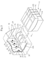
- Fig.2 is a schematic perspective view of an ink cartridge mounted on a head holder according to a first preferred embodiment of the invention.
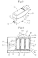
- Fig. 3 is a perspective view illustrating one cartridge from the front side.
- Fig. 4 is a cross sectional view of each cartridge mounted on the head holder.
- Fig. 5 is a longitudinal sectional view of the head holder illustrating each cartridge mounted on the head holder.
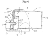
- Fig. 6 is a schematic view of a cartridge mounted in a wrong direction in the cartridge mounting section.
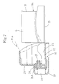
- Fig. 7 is a schematic view of a cartridge being mounted upside down from the front side in the cartridge mounting section.
- Fig. 8 is a schematic view of a cartridge being mounted upside down from the rear side in the cartridge mounting section.
- Fig. 9 is a schematic view of a cartridge mounted on the head holder according to a second preferred embodiment of the invention.
- Fig. 10 is a schematic view of a cartridge mounted on the head holder according to a third preferred embodiment of the invention.
- Fig. 11 is a schematic view of a cartridge mounted in a wrong direction in the cartridge mounting section.
- Fig. 12 is a longitudinal sectional view of a prior art ink cartridge.
- Fig. 13 is a longitudinal sectional view of the prior art ink cartridge mounted in a wrong direction on the head holder.
- Fig. 14 is a cross sectional view of the ink cartridge mounted on a conventional head holder.
- Hereinafter the preferred embodiments of the connecting structure of a head holder and an ink cartridge according to the invention will be explained with reference to the drawings. First, the general structure of an ink jet printer to which the connecting structure of the invention is incorporated will be explained, with reference to Fig. 1.
- Fig. 1 is a schematic perspective view of an ink jet printer. In Fig. 1, a platen 3 is mounted so as to rotate in the direction of arrow A in the housing 2 of a
printer 1. A guide shaft 4 is mounted generally parallel to the platen 3. Acarriage 5 is slidably mounted on the guide shaft 4. Abelt 6 is installed on thecarriage 5. Thebelt 6 is wrapped around an idle pulley 7 and adrive pulley 8. Thedrive pulley 8 is rotated by a drive, such as a driving motor 9. With the rotation of thedrive pulley 8, thecarriage 5 traverses along the guide shaft 4 via thebelt 6 in the direction of the arrow B in Fig. 1. - A
head holder 10 is mounted opposite the platen 3 on thecarriage 5. Further, anink cartridge 11 is mounted on thehead holder 10. Anink jet head 21 is installed on a front surface of thehead holder 10, as shown in Fig. 5. - A plurality of ink passages are formed in the
ink jet head 21. A nozzle (not illustrated) is provided, corresponding to each ink passage. As described hereinafter, the ink is supplied from theink cartridge 11 to theink jet head 21. - A
printing paper 12 is inserted at the rear part of the printer in the direction of arrow C in Fig. 1. Thepaper 12 is fed in along the platen 3, and is discharged out of the housing 2 in the direction of arrow D. As theprinting paper 12 is fed to the platen 3, ink is emitted from thejet head 21 as thecarriage 5 moves. Thus, data can be printed on thepaper 12. - A
cap 13 is provided in a nonprinting position of theink jet head 21 on the left side of the platen 3 in Fig. 1. Thecap 13 is fit with arubber cap 14 closely mounted to thehead 21. Thecap 13 is movably mounted to the head 2 in the direction of arrow E in Fig. 1. Thecap 13 is moved by a moving device or means (not illustrated), thus closely mounting therubber cap 14 to thehead 21. - The
cap 13 is connected to a connectingtube 15, which is connected with apump 16. Thepump 16 is connected with adischarge tube 17. Thedischarge tube 17 is connected with a usedink tank 19 in which an absorbent 18 is inserted. - A
flexible wiper blade 20 is provided between the platen 3 in the nonprinting position and thecap 13. Thewiper blade 20 is movably installed and moves in the direction of arrow F in Fig. 1. Thewiper blade 20 is normally maintained in the retreat position, where it_ is out of contact with thehead 21. During wiping, thewiper blade 20 is moved by a motor (not illustrated) to an advanced position, where it is in sliding contact with thehead 21. - Next, the connecting structure for connecting the
head holder 10 to theink cartridge 11 will be explained with reference to Fig. 2. Fig. 2 is a schematic perspective view of theink cartridge 11 mounted on thehead holder 10. - In Fig. 2, three
partition walls 23 are provided on abottom wall 22 of thehead holder 10. Between a pair ofside walls 24, thebottom wall 22 is divided by thepartition walls 23 into fourcartridge mounting sections - The
cartridge mounting section 22A is larger than the three othercartridge mounting sections 22B-22D. Acartridge 11A charged with black ink is mounted in thiscartridge mounting section 22A. Each of thecartridge mounting sections cartridges black ink cartridge 11A has a larger volume than the othercolor ink cartridges - Furthermore, on the inner surface side of a
front wall 25 of thehead holder 10, fourink supply members 26 are formed, corresponding to each of thecartridges 11A-11D. Eachink supply member 26 functions to supply the ink from eachcartridge 11A-11D to the ink jet head 21 (see Fig. 5) disposed on the outer surface of thefront wall 25. Amesh filter 27 is mounted on the front end ofink supply member 26. Eachmesh filter 27 functions removes foreign materials from the ink supplied from each of thecartridges 11A-11D, and to supply clean ink to theink jet head 21. A steppedsection 28 is formed adjacent to a stepped section 32 (described hereinafter) of thecartridges 11A-11D on the inner surface side of each side wall 24 (only the inner surface of oneside wall 24 is shown in Fig. 2). - Next, the structure of each of the
cartridges 11A-11D will be explained, with reference to Figs. 3 and 4. Fig. 3 is a perspectiveview showing cartridge 11A from the front side, and Fig. 4 is a cross section of each of thecartridges 11B-11D mounted on thehead holder 10. Thecartridge 11A has basically the same construction as the other threecartridges 11B-11D, except for a different size. Therefore, only thecartridge 11A will be explained as an example. - In Fig. 3, the
cartridge 11A has anink container 31 comprising two sections: anupper section 29 and alower section 30. The width L1 of theupper section 29 is greater than the width L2 of thelower section 30. Accordingly, a steppedsection 32 is formed at a boundary between theupper section 29 andlower section 30. The width L1 of theupper section 29 being greater than the width L2 of thelower section 30 will be described hereinafter with reference to specific structure. - An
insertion hole 33 for theink supply member 26 is provided on the front side (left surface side in Fig. 3) of theink container 31 of thecartridge 11A. Theinsertion hole 33 serves as an ink supply hole, through which the is supplied to the ink-impregnated body G (Fig. 5) in each of thecartridges 11A-11D, to the ink is supplied through themesh filter 27 and theink supply member 26 to theink jet head 21. - Furthermore, a cartridge cover or cover
body 35 is joined, for example by welding or shear welding, to the opening 34 (Fig. 4) of theupper section 29. On the rear surface side of the ink container 31 (right surface side in Fig. 3), a grip or protruding section H is formed protruding outwardly from an upper part. The grip section H facilitates holding theink cartridge 11A during replacement. - In each of the
cartridges 11B-11D, shown in Fig. 4, a pair of mutuallyopposite side walls 36 contact eachpartition wall 23. Theside walls 36 are integrally formed with theupper section 29 and thelower section 30. Theside walls 36 extend to theopening 34 and have a planar inner wall surface. Accordingly, the inner wall surfaces of theupper section 29 and thelower section 30 are substantially co-planar. - The
upper section 29 of theside wall 36 is formed of a suitable thickness, for example 1.5 mm thick. The inner side of the stepped section of theopening 34 of theink container 31 and the protrudingsection 35A on the underside of thecartridge cover 35 will be formed, for example by shear welding. On the other hand, thelower section 30 of theside wall 36 has a large wall thickness preventing deformation if thecartridge 11B is mounted between thepartition walls 23. Therefore, it is possible to decrease the wall thickness of thelower section 30 to be less than theupper section 29, for example 1.0 mm. Therefore, a difference of 0.5 mm between the wall thickness of theupper section 29 and that of thelower section 30 in theside wall 36 exists. Moreover, a difference of 1.0 mm between the width L1 of theupper section 29 and the width L2 of thelower section 30 in the twoside walls 36 also exists. - In each
cartridge 11A-11D, the width L1 of theupper section 29 is larger than the width L2 of thelower section 30. Furthermore, the inner wall surface of the pair of mutuallyopposite side walls 36, which integrally continue to theopening 34 of theink container 31, is substantially planar. The wall thickness, for example 1.0 mm, of thelower section 30 of theside wall 36 is less than the wall thickness, for example 1.5 mm of theupper section 29. - In conventional devices, the upper and lower sections have an equal width, and the side wall of the ink container has a constant thickness from the upper part to the lower part. On the other hand, each of the
cartridges 11A-11D of the invention is mounted to thecartridge mounting sections 22A-22D between thepartition walls 23, via thelower section 30 of theink container 31. Therefore, the cartridges have an increased volume with respect to conventional cartridges, and it is possible to increase the ink amount in theink container 31. In other words, it is possible to decrease the relative size of each of thecartridges 11A-11D, and accordingly decrease the size of thehead holder 10 and thecarriage 5, when compared with a conventional ink cartridge. - Next, the structure for connecting each of the
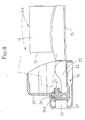
cartridges 11A-11D to theink jet head 21 in thehead holder 10 will be explained, with reference to Fig. 5. Fig. 5 is a longitudinal section view of thehead holder 10 showing each of thecartridges 11A-11D mounted on thehead holder 10. Each of thecartridges 11A-11D have the same general structure, and will be explained with reference to Fig. 5. - In Fig. 5,
cartridge 11A is mounted between thepartition walls 23 of thecartridge mounting section 22A on thebottom wall 22 in thehead holder 10. Thecartridge 11A has a semicircular lug protruding from the rear lower end thereof, so that an elastic locking member of the carriage engages it and prevents the rear end of the cartridge from raising up. When each of thecartridges 11A-11D is in its mounted position, the forward end (left end in Fig. 5) of theink supply member 26 is attached to the front surface of thehead holder 10, and is inserted into each of thecartridges 11A-11D through theinsertion hole 33. Thereby, themesh filter 27, attached to theink supply member 26, is pressed against the ink-impregnated body G in each of thecartridges 11A-11D. As a result, ink impregnated in the ink-impregnated body G is fed to theink jet head 21 through anink hole 26A of theink supply member 26, after removal of foreign matters by themesh filter 27. Theink jet head 21 is attached on thefront wall 25 of thehead holder 10, and ahead cover 37 is disposed around it. - Also, in each of the
cartridges 11A-11D, the protrusion distance or first protrusion distance of the grip section H from therear surface 31A of theink container 31 is X. In thehead holder 10, the protrusion distance or second protrusion distance of theink supply member 26 from theinner surface 25A of thefront wall 25 is W. The protrusion distance X of the grip section H is greater than the protrusion distance W of theink supply member 26. - A first height from the
upper surface 22A of thebottom wall 22 to the bottom edge H1 of the grip section H is Z. A second height from theupper surface 22A, which contacts the lower surface of theink container 31, of thebottom wall 22 in thehead holder 10 to thetop edge 26B of theink supply member 26 is Y. The grip section H is formed to extend rearwardly from each of thecartridges 11A-11D at a different height than the forward end of theink supply member 26. For example, the height can be at a level higher than the forward end of theink supply member 26, whereby the height Z to the bottom edge H1 of the grip section H is greater than the height Y to thetop edge 26B of theink supply member 26. - When the ink in each of the
cartridges 11A-11D is exhausted, each of thecartridges 11A-11D will be replaced. Acartridge 11A can be held by the grip section H, and mounted to thecartridge mounting section 22A. The width L1 of theupper section 29 in each of thecartridges 11A-11D is greater than the width L2 of thelower section 30. The mounting width of thecartridge mounting section 22A for mounting each of thecartridges 11A-11D is approximately the same as the width L2 of thelower section 29. Therefore, the mounting direction of each of thecartridges 11A-11D with respect to each of thecartridge mounting sections 22A-22D is predetermined preventing mis-mounting. - However, an operator may inadvertently attempt to mount a cartridge in a wrong direction or upside down in each of the
cartridge mounting sections 22A-22D during cartridge replacement. Since each of thecartridges 11A-11D is provided with theinsertion hole 33 only near the lower part of thefront surface 31B, the front upper wall section or rear wall section of thecartridges 11A-11D could contact themesh filter 27 mounted to theink supply member 26, damaging themesh filter 27. It is therefore necessary to prevent this contact to avoid damage. - The protrusion distance X of the grip section H is larger than the protrusion distance W of the
ink supply member 26. Also, the height Z to the bottom edge H1 of the grip section H is larger than the height Y to thetop edge 26B of theink supply member 26. Additionally, in each of thecartridges 11A-11D, the width L1 of theupper section 29 is larger than the width L2 of thelower section 30. Therefore, if any of thecartridges 11A-11D is mounted in a incorrect direction or orientation to each of thecartridge mounting sections 22A-22D, the wall surface of theink container 31 will be prevented from abutting themesh filter 27 of theink supply member 26. Also, the mounting each of thecartridges 11A-11D upside down in each of thecartridge mounting sections 22A-22D is prevented. - Here, improperly mounted cartridge, for
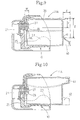
example cartridge 11A, will be explained with reference to Figs. 6-8. As thecartridges 11A-11D have substantially the same structure,cartridge 11A is shown as an example in Figs. 6-8. Fig. 6 is a schematic explanatory view illustrating a cartridge mounted in a wrong direction in a mountingsections 22A-22D; Fig. 7 is a schematic explanatory view of acartridge 11A, being mounted upside down from the front side to the cartridge mounting sections; and Fig. 8 is a schematic explanatory view of acartridge 11A being mounted upside down from the rear side to thecartridge mounting sections 22A-22D. - As shown in Fig. 5, when the
cartridge 11A is properly mounted to thecartridge mounting section 22A, theink supply member 26 attached on thehead holder 10, is inserted in theinsertion hole 33 of thecartridge 11A and presses the ink-impregnated body G to force the ink out. Thus, the ink is supplied to theink jet head 21 through theink hole 26A. Meanwhile, if thecartridge 11A is mounted in a wrong direction with respect to thecartridge mounting section 22A, theink supply member 26 will be positioned in a space defined by the grip section H and therear surface 31A of theink container 31, shown in Fig. 6. Accordingly, themesh filter 27 does not abut the wall surface, for example therear surface 31A of theink container 31. - The protrusion distance X of the grip section H is greater than the protrusion distance W of the
ink supply member 26, and the height Z to the bottom edge H1 of the grip section H is greater than the height Y to thetop edge 26B of theink supply member 26. Thereby, this structure reliably prevents themesh filter 27 from abutting the side surface of theink container 31. Accordingly, damage to themesh filter 27 is prevented. - Furthermore, if the
cartridge 11A is mounted upside down from the front side to thecartridge mounting section 22A, as shown in Fig. 7,thecartridge 11A can not be fit in and mounted in the mountingsection 22A. This is because the width L1 of theupper section 29 of thecartridge 11A is greater than the width of thecartridge mounting section 22A. Therefore, prevention of improper mounting of thecartridge 11A to the mountingsection 22A is achieved. This protects themesh filter 27 from damage. - As described above, if each of the
cartridges 11A-11D is mounted in a wrong or improper orientation or direction to thecartridge mounting section 22A-22D, theink supply member 26 will be within a space defined by the grip section H and therear surface 31A of theink container 31. Moreover, if each of thecartridges 11A-11D is mounted upside down from the front side to thecartridge mounting section 22A-22D, or similarly from the rear side to thecartridge mounting section 22A-22D, thecartridge 11A-11D can not be mounted in each of thecartridge mounting sections 22A-22D. Therefore, damage to themesh filter 27 is prevented. - As explained, the protrusion distance X of the grip section H protruding outward from the
rear surface 31A of theink container 31 is greater than the protrusion distance W of theink supply member 26 in thehead holder 10 from theinner surface 25A of thefront wall 25. Also, the height Z from the bottom edge H1 of the grip section H to theupper surface 22A of thebottom wall 22 in thehead holder 10 is greater than the height Y from theupper surface 22A of thebottom wall 22 to thetop edge 26B of theink supply member 26. Therefore, if each of thecartridges 11A-11D is mounted in a wrong direction to each of thecartridge mounting sections 22A-22D, a space defined by the grip section H and therear surface 31A of theink container 31 will prevent themesh filter 27 from abutting and contacting the wall surface of theink container 31. Thereby, damage to themesh filter 27 is prevented. - Also, the width L1 of the
upper section 29 of theink cartridge 11A is larger than the width L2 of thelower section 30. Furthermore, the inner wall surfaces of the pair of mutuallyopposite side walls 36 are substantially flat, and integrally continuing to theopening 34 of theink container 31 in thecartridge 11A. In eachcartridge side wall 36, the wall thickness of thelower section 30 is smaller than that of theupper section 29. Thus, eachcartridge 11A can only be mounted in thecartridge mounting section 22A between thepartition walls 23 formed on thebottom plate 22 of thehead holder 10 through thelower section 30 of theink container 31 in the proper orientation. Moreover, the amount of ink to be charged in the cartridge can be increased. - Furthermore, if each of the
cartridges 11A-11D is mounted upside down from the front side in thecartridge mounting section 22A-22D, or similarly from the rear side in thecartridge mounting section 22A-22D, it is impossible to mount each of thecartridges 11A-11D. Accordingly, each of thecartridges 11A-11D can be prevented from being mounted upside down, and thereby reliably prevent damaging themesh filter 27. - Furthermore, as compared with a conventional ink cartridge in which the upper and lower sections are formed with the same width and each side wall of the ink container has a constant thickness from the upper and the lower sections, the
instant ink cartridge 11 of the connecting structure allows for an increased amount of ink in the ink container. In other words, each of thecartridges 11A-11D can have a smaller relative size than conventional ink cartridges, without changing the amount of ink in each of the cartridges. Consequently, thehead holder 10 and thecarriage 5 can be made smaller. - The invention is not limited to the embodiment explained herein. Various improvements and modifications are possible within the scope and spirit of the invention.
- For example, the grip section H protruding at the upper rear part of the
cartridge 11A-11D is formed as to function as a protrusion. However, aprotrusion 40 may be provided protruding rearwardly from a lower rear surface of thecartridge 11A-11D at different levels from the forward end of theink supply member 26. As shown in a second preferred embodiment of Fig. 9, theink supply member 26 is mounted in an upper part of thefront wall 25 of thehead holder 10. In this second preferred embodiment, the height Z from thecartridge cover 35 to the top edge H1 of the grip section is larger than the height Y from thecartridge cover 35 to thebottom edge 26C. Thus, thecartridge 11A-11D when mounted in a wrong direction in thehead holder 10 will not have its rear surface contact the forward end of theink supply member 26. This reliably prevents damage to themesh filter 27. - A third preferred embodiment is illustrated in Figs. 10 and 11. Similar characters are represented by similar reference numbers for the other preferred embodiments. The
ink supply member 26 is attached at a vertical mid-point in the direction of thehead holder 10. Aprotrusive section 41 is provided and protrudes rearwardly at a level different from the forward end of theink supply member 26. Theprotrusive section 41 protrudes from the rear uppermost section of thecartridge 11A-11D. Also, a furtherprotrusive section 42 protrudes rearwardly from the rear lowermost section of thecartridge 11A-11D. Bothprotrusive sections - As is clear from Fig. 11, the rear surface of the
cartridge 11A-11D when mounted in a wrong direction in thehead holder 10, will not contact the forward end of theink supply member 26. This reliably prevents damage to themesh filter 27. When bothprotrusion sections side walls 36 of theink container 31 may extended further rearwardly between theseprotrusion sections ink supply member 26 will be loosely fit within the space due to the contact of one or both of theprotrusive sections front wall 25. - While this invention has been described in conjunction with specific embodiments thereof, it is evident that many alternatives, modifications and variations will be apparent to those skilled in the art. Accordingly, the preferred embodiments of the invention as set forth herein are intended to be illustrative, not limiting. Various changes may be made without departing from the scope of the invention as defined in the following claims.
Claims (14)
- A connecting structure comprising:
a head holder (10) having:a front wall (25);a bottom wall (22); andan ink supply member (26) for supplying ink to an ink jet head and protruding inwardly from an inner surface of said front wall (25) by an ink supply member protrusion distance; anda cartridge mounting section (22A,B,C,D) formed in said bottom wall (22);an ink cartridge (11) to be mounted in said cartridge mounting section and having a substantially rectangular shape, the ink cartridge (11) having:an insertion hole (33) formed in a front surface of said ink cartridge (11) and for facing the inner surface of said front wall (25) of said head holder (10), the insertion hole (33) allowing said ink supply member to communicate with interior of the cartridge; anda protruding section (29) protruding outwardly from a rear surface of said ink cartridge (11) opposite to said front surface by a protruding section protrusion distance at a height different from a height of said ink supply member;wherein the protruding section protrusion distance is greater than the ink supply member protrusion distance. - A connecting structure according to claim 1, wherein said head holder comprises at least one partition wall (23) for positioning an ink cartridge (11), the partition wall (23) is in contact with a portion of said ink cartridge, and an ink cartridge having a width smaller at the portion in contact with said partition wall than at other portions of the ink cartridge.
- A connecting structure according to claim 1 or 2 further comprising:
a filter (27) mounted at an end of said ink supply member (26). - A connecting structure according to claim 3, wherein the filter is a mesh filter (27) for removing impurities from the ink within the ink cartridge.
- A connecting structure according to any one of claims 1 to 4, where said protruding section (29) comprises a grip section (H) protruding outwardly from an inner part of the rear surface of said ink cartridge (11), wherein the grip section comprising a bottom edge, a first height defined from an upper surface of said bottom wall of said head holder (10) to the bottom edge of said grip section is greater than a second height defined from the upper surface of said bottom wall to the top edge of said ink supply member.
- A connecting structure according to any preceding claim wherein the ink cartridge (11) comprises an upper section (29) having a first width (L1) and a lower section (30) having a second width (L2) different than the first width.
- A connecting structure according to claim 6, wherein the ink cartridge further comprises a stepped portion separating the upper and lower portions.
- A connecting structure according to claim 6 or 7, wherein the first width (L1) is greater than the second width (L2).
- A connecting structure according to claim 6, 7 or 8, wherein said head holder comprises a plurality of partition walls (23) for positioning therebetween at least one ink cartridge, each adjacent partition wall is separated by a width substantially equal to the second width of the lower portion (29) of the ink cartridge (11).
- A connecting structure according to any preceding claim, wherein the ink cartridge (11) is for contact with and for positioning between partition walls (23) of the head holder (10) and has a width smaller at the portion in contact with said partition wall than at other portions.
- A connecting structure according to any preceding claim wherein the ink cartridge further comprises a separate cover joined to the ink cartridge.
- A connecting structure according to any preceding claim, wherein the protruding section protrudes outwardly from an upper portion of the rear surface of the ink cartridge.
- A connecting structure according to any one of claims 1 to 12 wherein the protruding section (40) protrudes outwardly from a lower portion of the rear surface of the ink cartridge.
- A connecting structure according to any preceding claim wherein the ink cartridge includes an ink-impregnated body.
Applications Claiming Priority (3)
| Application Number | Priority Date | Filing Date | Title |
|---|---|---|---|
| JP21667095 | 1995-08-01 | ||
| JP216670/95 | 1995-08-01 | ||
| JP21667095A JP3479392B2 (en) | 1995-08-01 | 1995-08-01 | Connection structure of ink cartridge |
Publications (3)
| Publication Number | Publication Date |
|---|---|
| EP0756937A2 EP0756937A2 (en) | 1997-02-05 |
| EP0756937A3 EP0756937A3 (en) | 1998-06-10 |
| EP0756937B1 true EP0756937B1 (en) | 2001-10-24 |
Family
ID=16692091
Family Applications (1)
| Application Number | Title | Priority Date | Filing Date |
|---|---|---|---|
| EP96305641A Expired - Lifetime EP0756937B1 (en) | 1995-08-01 | 1996-07-31 | Connecting structure for printing head and ink cartridge |
Country Status (6)
| Country | Link |
|---|---|
| US (1) | US5949457A (en) |
| EP (1) | EP0756937B1 (en) |
| JP (1) | JP3479392B2 (en) |
| CN (1) | CN1143017A (en) |
| AU (1) | AU713690B2 (en) |
| DE (1) | DE69616202T2 (en) |
Families Citing this family (4)
| Publication number | Priority date | Publication date | Assignee | Title |
|---|---|---|---|---|
| US6188417B1 (en) | 1994-10-31 | 2001-02-13 | Hewlett-Packard Company | Fluidic adapter for use with an inkjet print cartridge having an internal pressure regulator |
| US6273560B1 (en) * | 1994-10-31 | 2001-08-14 | Hewlett-Packard Company | Print cartridge coupling and reservoir assembly for use in an inkjet printing system with an off-axis ink supply |
| US6779874B2 (en) * | 2001-07-31 | 2004-08-24 | Hewlett-Packard Development Company, Lp. | Device for ensuring proper toe-heel installation of a detachable printer component |
| CN109318596B (en) * | 2017-07-31 | 2021-04-30 | 兄弟工业株式会社 | Liquid consumption device and liquid consumption system |
Family Cites Families (13)
| Publication number | Priority date | Publication date | Assignee | Title |
|---|---|---|---|---|
| DE299360C (en) * | ||||
| DE2543991C3 (en) * | 1975-10-02 | 1980-04-10 | Olympia Werke Ag, 2940 Wilhelmshaven | Ink reservoir for ink pens |
| US4593294A (en) * | 1985-04-22 | 1986-06-03 | Exxon Printing Systems, Inc. | Ink jet method and apparatus |
| JPS6357243A (en) * | 1986-08-28 | 1988-03-11 | Toshiba Corp | Recorder |
| IT1232551B (en) * | 1989-07-13 | 1992-02-19 | Olivetti & Co Spa | PRINT HEAD FOR A INK-JET THERMAL PRINTER |
| US5488401A (en) * | 1991-01-18 | 1996-01-30 | Seiko Epson Corporation | Ink-jet recording apparatus and ink tank cartridge thereof |
| CA2084708C (en) * | 1991-12-11 | 1997-11-25 | Hiromitsu Hirabayashi | Ink jet recording apparatus and carriage mechanism therefor |
| JP2962044B2 (en) * | 1992-05-29 | 1999-10-12 | 富士ゼロックス株式会社 | Ink tank, inkjet cartridge, and inkjet recording device |
| US5509140A (en) * | 1992-07-24 | 1996-04-16 | Canon Kabushiki Kaisha | Replaceable ink cartridge |
| CA2101017C (en) * | 1992-07-24 | 1999-10-26 | Masahiko Higuma | Ink jet cartridge, ink jet head and printer |
| JP3133906B2 (en) * | 1993-08-19 | 2001-02-13 | キヤノン株式会社 | Ink tank cartridge |
| US5619239A (en) * | 1993-11-29 | 1997-04-08 | Canon Kabushiki Kaisha | Replaceable ink tank |
| JP3280202B2 (en) * | 1995-08-01 | 2002-04-30 | ブラザー工業株式会社 | Inkjet printer |
-
1995
- 1995-08-01 JP JP21667095A patent/JP3479392B2/en not_active Expired - Lifetime
-
1996
- 1996-04-26 US US08/638,564 patent/US5949457A/en not_active Expired - Lifetime
- 1996-07-31 DE DE69616202T patent/DE69616202T2/en not_active Expired - Lifetime
- 1996-07-31 AU AU60846/96A patent/AU713690B2/en not_active Ceased
- 1996-07-31 EP EP96305641A patent/EP0756937B1/en not_active Expired - Lifetime
- 1996-08-01 CN CN96111788.5A patent/CN1143017A/en active Pending
Also Published As
| Publication number | Publication date |
|---|---|
| AU713690B2 (en) | 1999-12-09 |
| JPH0939267A (en) | 1997-02-10 |
| DE69616202T2 (en) | 2002-04-18 |
| US5949457A (en) | 1999-09-07 |
| AU6084696A (en) | 1997-02-06 |
| EP0756937A2 (en) | 1997-02-05 |
| EP0756937A3 (en) | 1998-06-10 |
| DE69616202D1 (en) | 2001-11-29 |
| JP3479392B2 (en) | 2003-12-15 |
| CN1143017A (en) | 1997-02-19 |
Similar Documents
| Publication | Publication Date | Title |
|---|---|---|
| US5534899A (en) | Replaceable ink tank | |
| US6070975A (en) | Ink jet recording apparatus and a method for installing ink jet recording head | |
| US5604523A (en) | Ink container, an ink jet cartridge and ink jet recording apparatus | |
| JP3745161B2 (en) | Liquid storage container | |
| EP1219445B1 (en) | Ink cartridge | |
| KR20020068465A (en) | Inkjet head and inkjet printer | |
| US12521993B2 (en) | Liquid container | |
| EP1832428B1 (en) | Liquid ejection apparatus having liquid transfer device | |
| EP0756937B1 (en) | Connecting structure for printing head and ink cartridge | |
| US6120128A (en) | Container for safekeeping ink cartridge | |
| JP3873502B2 (en) | Inkjet recording device | |
| US5872578A (en) | Capping device for ink jet head in ink jet printer | |
| US9561663B2 (en) | Ink cartridge and printer | |
| JPH07179004A (en) | Inkjet head cartridge and inkjet recording apparatus | |
| JP7135602B2 (en) | tanks and liquid consumers | |
| US20240217240A1 (en) | Inkjet printer | |
| US11179954B2 (en) | Printer | |
| JPH07304190A (en) | Liquid jet recording device | |
| WO2025100299A1 (en) | Liquid container | |
| AU2002301858B2 (en) | Ink Tank, Ink Jet Head Cartridge, and Ink Jet Recording Apparatus | |
| JP2007111864A (en) | Recording liquid cartridge and image forming apparatus | |
| JP2004122460A (en) | Ink tank holder |
Legal Events
| Date | Code | Title | Description |
|---|---|---|---|
| PUAI | Public reference made under article 153(3) epc to a published international application that has entered the european phase |
Free format text: ORIGINAL CODE: 0009012 |
|
| AK | Designated contracting states |
Kind code of ref document: A2 Designated state(s): CH DE FR GB LI |
|
| PUAL | Search report despatched |
Free format text: ORIGINAL CODE: 0009013 |
|
| AK | Designated contracting states |
Kind code of ref document: A3 Designated state(s): CH DE FR GB LI |
|
| 17P | Request for examination filed |
Effective date: 19980806 |
|
| 17Q | First examination report despatched |
Effective date: 19990624 |
|
| GRAG | Despatch of communication of intention to grant |
Free format text: ORIGINAL CODE: EPIDOS AGRA |
|
| GRAG | Despatch of communication of intention to grant |
Free format text: ORIGINAL CODE: EPIDOS AGRA |
|
| GRAH | Despatch of communication of intention to grant a patent |
Free format text: ORIGINAL CODE: EPIDOS IGRA |
|
| GRAH | Despatch of communication of intention to grant a patent |
Free format text: ORIGINAL CODE: EPIDOS IGRA |
|
| GRAA | (expected) grant |
Free format text: ORIGINAL CODE: 0009210 |
|
| AK | Designated contracting states |
Kind code of ref document: B1 Designated state(s): CH DE FR GB LI |
|
| PG25 | Lapsed in a contracting state [announced via postgrant information from national office to epo] |
Ref country code: LI Free format text: LAPSE BECAUSE OF FAILURE TO SUBMIT A TRANSLATION OF THE DESCRIPTION OR TO PAY THE FEE WITHIN THE PRESCRIBED TIME-LIMIT Effective date: 20011024 Ref country code: CH Free format text: LAPSE BECAUSE OF FAILURE TO SUBMIT A TRANSLATION OF THE DESCRIPTION OR TO PAY THE FEE WITHIN THE PRESCRIBED TIME-LIMIT Effective date: 20011024 |
|
| REG | Reference to a national code |
Ref country code: CH Ref legal event code: EP |
|
| REF | Corresponds to: |
Ref document number: 69616202 Country of ref document: DE Date of ref document: 20011129 |
|
| ET | Fr: translation filed | ||
| REG | Reference to a national code |
Ref country code: GB Ref legal event code: IF02 |
|
| REG | Reference to a national code |
Ref country code: CH Ref legal event code: PL |
|
| PLBE | No opposition filed within time limit |
Free format text: ORIGINAL CODE: 0009261 |
|
| STAA | Information on the status of an ep patent application or granted ep patent |
Free format text: STATUS: NO OPPOSITION FILED WITHIN TIME LIMIT |
|
| 26N | No opposition filed | ||
| REG | Reference to a national code |
Ref country code: FR Ref legal event code: PLFP Year of fee payment: 20 |
|
| PGFP | Annual fee paid to national office [announced via postgrant information from national office to epo] |
Ref country code: GB Payment date: 20150624 Year of fee payment: 20 |
|
| PGFP | Annual fee paid to national office [announced via postgrant information from national office to epo] |
Ref country code: FR Payment date: 20150624 Year of fee payment: 20 |
|
| PGFP | Annual fee paid to national office [announced via postgrant information from national office to epo] |
Ref country code: DE Payment date: 20150731 Year of fee payment: 20 |
|
| REG | Reference to a national code |
Ref country code: DE Ref legal event code: R071 Ref document number: 69616202 Country of ref document: DE |
|
| REG | Reference to a national code |
Ref country code: GB Ref legal event code: PE20 Expiry date: 20160730 |
|
| PG25 | Lapsed in a contracting state [announced via postgrant information from national office to epo] |
Ref country code: GB Free format text: LAPSE BECAUSE OF EXPIRATION OF PROTECTION Effective date: 20160730 |