EP1219445B1 - Ink cartridge - Google Patents
Ink cartridge Download PDFInfo
- Publication number
- EP1219445B1 EP1219445B1 EP02006452A EP02006452A EP1219445B1 EP 1219445 B1 EP1219445 B1 EP 1219445B1 EP 02006452 A EP02006452 A EP 02006452A EP 02006452 A EP02006452 A EP 02006452A EP 1219445 B1 EP1219445 B1 EP 1219445B1
- Authority
- EP
- European Patent Office
- Prior art keywords
- ink
- cartridge
- wall
- walls
- ink cartridge
- Prior art date
- Legal status (The legal status is an assumption and is not a legal conclusion. Google has not performed a legal analysis and makes no representation as to the accuracy of the status listed.)
- Expired - Lifetime
Links
Images


Classifications
-
- B—PERFORMING OPERATIONS; TRANSPORTING
- B41—PRINTING; LINING MACHINES; TYPEWRITERS; STAMPS
- B41J—TYPEWRITERS; SELECTIVE PRINTING MECHANISMS, i.e. MECHANISMS PRINTING OTHERWISE THAN FROM A FORME; CORRECTION OF TYPOGRAPHICAL ERRORS
- B41J2/00—Typewriters or selective printing mechanisms characterised by the printing or marking process for which they are designed
- B41J2/005—Typewriters or selective printing mechanisms characterised by the printing or marking process for which they are designed characterised by bringing liquid or particles selectively into contact with a printing material
- B41J2/01—Ink jet
- B41J2/17—Ink jet characterised by ink handling
- B41J2/175—Ink supply systems ; Circuit parts therefor
- B41J2/17503—Ink cartridges
- B41J2/1752—Mounting within the printer
Definitions
- the invention relates to an ink cartridge which is detachably mounted on a head holder which is provided to an ink jet printer.
- it relates to an ink cartridge in which the ink volume can be increased while miniaturizing the head holder and the ink cartridge can be prevented from being erroneously mounted on the head holder.
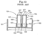
- Fig. 13 is a cross-sectional view showing an ink cartridge mounted on a head holder.
- the head holder 100 has a pair of side walls 101, and a plurality of partition walls 103 (three partition walls are shown in Fig. 13) are formed on a bottom wall 102 which is formed between the side walls 101.
- An ink cartridge 104 filled with ink (not shown) is mounted between the respective partition walls 103.
- Each ink cartridge 104 comprises an ink tank 106 which is designed in a substantially rectangular parallelepiped shape having an opening at the upper portion thereof.
- a cartridge lid 106 is welded to the peripheral edge of the opening of the ink tank 105 to close the ink tank 105.
- the peripheral edge of the ink tank 105 and the carriage lid 106 are generally welded to each other by an ultrasonic welding method and, particularly, the welding surfaces of the ink tank 105 and the cartridge lid 106 are welded to each other by a shear welding method which provides a strong welding force.
- a shear welding method which provides a strong welding force.
- the outer side portion of each projection 107 formed on the lower surface of the cartridge lid 106 is welded to the inner side portion of a step portion at the peripheral edge of the opening which is formed in the ink tank 105. Therefore, in consideration of the requirements of shear welding, the thickness of the peripheral edge of the opening in the ink tank 105 must be set to 1.5mm at a minimum.
- the ink tank 105 is designed so that the thickness of each side wall 108 of the pair of confronting side walls 108 is set to 1.5mm over the whole body.
- each side wall 108 of the ink tank 105 is designed to have an uniform thickness over the whole body thereof (1.5mm).
- the thickness of each side wall 108 is excessively large for a disposable ink cartridge and, thus, it must be further thinned.
- each partition wall 103 formed on the bottom wall 102 of the head holder 100 it is required to keep the thickness of the partition wall 103 to the minimum thickness at which it can be formed, and also it is required to reduce the width of the head holder 100 as much as possible in order to miniaturize a carriage on which the head holder is mounted. Therefore, the width between the respective partition walls 103 is set to substantially a fixed value. Accordingly, when the thickness of each side wall 108 of the ink tank 105 is set to a large value as described above, the volume which can be secured in the ink tank 105 is reduced by the amount corresponding to the thickness, so that the amount of ink stocked in the ink cartridge 104 is reduced. In other words, in order to stock a constant amount of ink into the ink cartridge 104, the ink cartridge 104 must be designed to have large size. This causes the head holder 100 to be large in size, and thus the carriage is also large in size.
- an ink supply port 109 is formed at the lower position and an ink supply member, provided with an ink filter at the end face thereof, which serves to supply ink to an ink jet head (not shown in Fig. 13) and is provided to the head holder 100, is inserted into the ink supply port 109.
- the ink cartridge 104 has the same shape at the upper and lower portion thereof, so that there may be a case where the ink supply member which should be inserted into the ink supply port 109 will oppose a portion of the ink cartridge 104 other than the ink supply port 109, i.e., a wall of the ink tank 105, and the ink supply portion is damaged.
- EP 0639462A discloses an ink cartridge and ink jets apparatus in which the ink cartridge has a wider upper portion than lower portion. The upper portion extends across the adjacent cartridge mounting portion.
- EP 0663295A and GB 2017006 disclose an ink filling apparatus and ink supply arrangement respectively. Both documents disclose ink cartridges with wider upper portions than lower portions.
- an ink printing device comprising:
- the upper and lower portions are designed to be different in width. Therefore, by designing the ink cartridge so that the one of the upper and lower portions of the ink cartridge which is smaller in width can be mounted between partition walls of the head holder, the width of the other portion of the ink cartridge which is not contacted with the partition walls can be designed to be larger by at least the amount corresponding to the thickness of the partition wall. Accordingly, as compared with the case where the ink cartridge is designed to have the same width over the whole body extending from the upper portion to the lower portion, a larger amount of ink can be stocked in the ink cartridge. In addition, only one of the upper and lower portions of the ink cartridge which is smaller in width can be mounted between the partition walls of the head holder. It is impossible to mount the ink cartridge between the partition walls while the cartridge is turned upside down. Therefore, the ink cartridge can be surely prevented from being erroneously mounted on the head holder.
- an ink cartridge of the invention has an ink tank which has an opening at either one of the upper and the lower portions and is designed in a substantially rectangular shape, and a lid member, which is-adhesively attached to the peripheral edge of the opening, serves to close the ink tank, wherein the width of the ink tank at the portion having the opening is set to be larger than that of the other portion, and a pair of side walls which confront each other in the width direction of the ink tank are designed so as to have a smaller thickness at the portion having the smaller width.
- the pair of side walls which confront each other in the width direction of the ink tank are designed so as to have a smaller thickness at the portion having the smaller width. Therefore, as compared with the case where the ink cartridge is designed to have the same width over the whole body extending from the upper portion to the lower portion, the ink amount to be stocked can be further increased by the amount corresponding to the reduction in thickness of the walls.
- the side wall portion in the neighborhood of the peripheral edge of the opening keeps such a sufficient thickness as is adhesively attached to the lid member, so that the lid member and the ink tank can be surely adhesively attached to each other.
- the inner wall surfaces of a pair of side walls confronting each other in the width direction of the ink tank can be designed to be flat.
- the inner wall surfaces of the pair of side walls are designed in a flat shape, so that the ink tank can be easily manufactured at low cost by resin molding or the like and the ink amount to be stocked can be increased without complicating manufacture. Still further, the lid member can be adhesively attached to the ink tank by shear welding.
- the lid member can be surely adhesively attached to the ink tank by shear welding which can provide the highest adhesive strength in an ultrasonic welding.
- the side wall whose thickness is sufficient for shear -welding is secured at the peripheral edge of the opening of the ink tank to which the lid member adheres. Therefore, the lid member and the ink tank can be firmly bonded into one body and the ink cartridge having large ink volume can be manufactured.
- an ink cartridge which can increase the ink volume with concurrent miniaturizing of the head holder and one that can be surely prevented from being erroneously mounted on the head holder.
- a platen 3 is provided in a housing 2 so as to be rotatable in the' directions indicated by the arrow A.
- a guide shaft 4 is provided along the platen 3.
- a carriage 5 is slidably secured to the guide shaft 4 and a belt 6 is secured to the carriage 5.
- the belt 6 is suspended over an idle pulley 7 and a driving pulley 8.
- the driving pulley 8 is rotated by a driving motor 9 and upon rotation of the driving pulley 8, the carriage 5 is moved in the directions indicated by arrow B along the guide shaft 4.
- a head holder 10 is secured on the carriage 5 so as to confront the platen 3 and an ink cartridge 11 is mounted on the head holder 10.
- An ink jet head 21 (Fig. 5) is secured to the front surface of the head holder 10.
- ink channels are formed in the ink jet head 21, and a nozzle (not shown) is provided for each ink channel. As described later, ink is supplied from the ink cartridge 11 to the ink jet head 21.
- a print sheet 12 is inserted from the rear side of the printer 1 into the housing 2, in the directions indicated by arrow C, and is fed around the platen 3 to exit in the directions indicated by arrow D, and is discharged from the housing 2.
- the ink jet head 21 (Fig. 5) which is fixed to the head holder 10 jets ink coordinated with the movement of the carriage 5 to print the desired data.
- a cap 13 is provided at a non-print position of the ink jet head 21 at the left side of the platen 3 and a cap rubber 14 is secured to the cap 13 to bring the cap 13 into close contact with the ink jet head 21.
- the cap 13 is mounted so as to be slidable relatively to the ink jet head 21 in the directions indicated by arrow E.
- the cap 13 is moved by a moving means (not shown) so that the cap rubber 14 suitably comes into close contact with the ink jet head 21.
- a link tube 15 is attached between the cap 13 and a pump 16.
- the pump 16 has a discharge tube 17 exiting therefrom to a waste ink tank 19 in which an adsorbent member 18 is held.
- a flexible wiper blade 20 is provided between the platen 3 and the cap 13 at the non-print position.
- the wiper blade 20 is mounted to be slidable in the directions indicated by arrow F.
- the wiper blade 20 is retracted to a backward position to break contact with the ink jet head 21.
- the wiper blade 20 is moved to an advanced position so as to come into slidable contact with the ink jet head 21 by the motor (not shown).
- Fig. 2 is a perspective view which schematically shows a state where the ink cartridge 11 is to be mounted on the head holder 10.
- the cartridge mount portion 22A is designed to be larger in size than the other three cartridge portions 22B,22C,22D.
- a cartridge 11A filled with black ink in ink cartridges 11 is mounted to the cartridge mount portion 22A.
- the respective cartridge mount portions 22B,22C,22D are designed to have the same size, and the ink cartridges 11B,11C,11D, which are filled with cyan ink, magenta ink and yellow ink respectively, are respectively mounted on the cartridge mount portions 22B,22C,22D.
- the cartridge 11A with the black ink, is designed to have a larger volume than the other cartridges 11B,11C,11D filled with the other three colors of ink in consideration of the fact that the frequency of use of black ink is higher than the other colors of ink.
- Each ink supply member 26 serves to feed the ink supplied from the associated ink cartridge 11 to the ink jet head 21 (Fig. 5) which is provided on the outer surface of the front wall 25 .
- a mesh filter 27 is secured to the tip portion of each ink supply member 26. The mesh filter 27 serves to remove dust found in the ink supplied from the ink cartridge 11 and to supply clean ink to the ink jet head 21.
- a step portion 28 is formed on the inner surface side of each side wall 24 (only the inner surface of one side wall 24 is shown in Fig. 2) so as to be proximately confronted to, and complementary of, the step portion 32 (described later) of the ink cartridges 11A and 11D adjacent thereto.
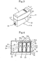
- Fig. 3 is a perspective view showing the cartridge 11A which is taken from the front side
- Fig. 4 is a cross-sectional view showing ink cartridges 11B-11D which are mounted on the head holder 10.
- the respective ink cartridges 11A-11D have the same basic structure except that the ink cartridge 11A has a different size from the other three ink cartridges 11B-11D. Therefore, the description with reference to Fig. 3 is made referring to the ink cartridge 11A. Further, in Fig. 4, only the cartridges 11B to 11D are shown.
- the ink cartridge 11A has two portions of an ink tank 31 comprising an upper portion 29 and a lower portion 30.
- the width L1 of the upper portion 29 is set to be larger than the width L2 of the lower portion.
- the step portion 32 is formed at the boundary between the upper portion 29 and the lower portion 30.
- a pair of side walls 36 which are continuously extended from the opening 34 in the ink tank 31 and confront each other (the lower portion 30 of the side walls 36 are contacted with the respective partition walls 23, and the upper portion 29 and the lower portion 30 thereof are formed integrally) are designed to have flat inner wall surfaces.
- the inner wall surfaces of the upper portion 29 and the lower portion 30 exist on the same plane.
- the thickness of the upper portion 29 of the side wall 36 is set to 1.5mm, for example, in consideration of the fact that the inside of the step portion of the opening 34 of the ink tank 31 is welded to the projection 35A formed on the lower surface of the cartridge lid 35 by shear welding.
- the thickness of the lower portion 30 of the side wall 36 is set to be smaller than that of the upper portion 29 because the lower portion 30 is not directly related to the shear welding.
- it is sufficient to be rigid to the extent that it is prevented from being deformed when it is mounted between the partition walls 23 and, for example, the thickness of the lower portion 30 is set to 1.0mm.
- each side wall 36 there is a thickness difference of 0.5mm between the thickness of the upper portion 29 and the thickness of the lower portion 30.
- the width L1 of the upper portion 29 is set to be larger than the width L2 of the lower portion 30, and further the inner wall surfaces of the pair of side walls 36 which are continuously and integrally extended from the opening 34 of the ink tank 31 and confront each other are designed in a flat shape. Further, in each side wall 36, the thickness of the lower portion 30 (1.0mm) is set to be smaller than the thickness of the upper portion 29 (1.5mm).
- Each ink cartridge 11A-11D is mounted at the lower portion 30 of the ink tank 31 on the respective cartridge mount portion 22A-22D between the respective partition walls 23 formed on the bottom plate 22 of the head holder 10.
- the amount of the ink which can be stocked in the ink tank 31 can be increased as compared with the conventional ink cartridge in which the upper and lower portions are designed to have the same width and each side wall of the ink tank is designed to have the same thickness over the whole body from the upper portion to the lower portion.
- the ink cartridge 11A-11D can be more miniaturized which enables miniaturization of the head holder 10 and the carriage 5.
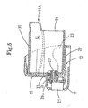
- FIG. 5 is a longitudinally sectional view of the head holder 10, which shows the head holder 10 is mounted with the ink cartridges 11A-11D.
- the ink cartridge 11A is -representatively described because the respective ink cartridges 11A-11D have substantially the same structure.
- the ink cartridge 11A is mounted at the cartridge mount portion 22A between the partition walls 23 on the bottom wall 22 of the head holder 10.
- An elastic holding member on the carriage (not shown) is suitably engaged with a semi-circular projection which projects from the lower end portion of the rear surface of the ink cartridge 11A to prevent the rear portion of the ink cartridge 11A from rising up.
- the tip portion (right end portion in Fig. 5) of the ink supply member 26 provided on the front surface of the head holder 10 is inserted through the ink supply port 33 of the ink cartridge 11A into the ink cartridge 11A and the mesh filter 27, secured to the ink supply member 26, is pressed against the ink absorber G mounted in the ink cartridge 11A.
- the ink absorbed in the ink absorber G is supplied from an ink hole 26A of the ink supply member 26 after dust and other contaminants are removed from the ink by the mesh filter 27.
- the ink jet head 21 is secured to the front wall 25 of the head holder 10, and a head cover 37 is disposed on the periphery thereof.
- the ink cartridge 11A When the ink of an ink cartridge 11A thus structured is exhausted, the ink cartridge 11A is exchanged.
- the width L1 of the upper portion 29 is set to be larger than the width L2 of the lower portion 30, and the mount width of the cartridge mount portion 22A-22D on which the respective ink cartridge 11A-11D is mounted is set to be substantially equal to the width L2 of the lower portion 29 of the ink cartridge 11.
- the mounting direction for each ink cartridge 11 on the corresponding cartridge mount portion 22 is predetermined. However, there may be a case where an operator attempts to mount the ink cartridge 11 on the cartridge mount portion 22 with the top of the cartridge turned down.
- the ink supply port 33 is formed only at a lower side of the front surface of each ink cartridge 11, the upper wall portion on the front surface or the wall portion of the rear surface of the ink cartridge 11 may be brought into contact with the mesh filter 27 secured to the ink supply member 26, so that the mesh filter is damaged. Therefore, it is necessary to effectively prevent this damage.
- the width L1 of the upper portion-29 is set to be larger than the-width L2 of the lower portion 30 as described above, whereby the ink cartridges 11 can be prevented from being mounted on the corresponding cartridge mount portions 22 when turned upside down.
- the structure to prevent the erroneous mounting of the respective ink cartridges 11A-11D will be described with reference to Figs. 6 and 7.
- Fig. 6 is a schematic diagram showing an attempt to mount the ink cartridge 11A on the cartridge mount portion 22A from the front surface side while the ink cartridge 11A is turned upside down.
- Fig. 7 is a schematic diagram showing an attempt to mount the ink cartridge 11A on the cartridge mount portion 22A from the rear side and turned upside down.
- the ink cartridge 11A is representatively illustrated because the respective cartridges 11A-11D have the same basic structure.
- the ink supply member 26 of the head holder 10 When the ink cartridge 11 is properly mounted on the cartridge mount portion 22, the ink supply member 26 of the head holder 10 is engagedly inserted into the ink supply port 33 of the cartridge 11, as shown in Fig. 5, and presses the ink absorber G, whereby the ink absorbed in the ink absorber G can be supplied from the ink hole 26 to the ink jet head 21.
- the ink cartridge 11 cannot be mounted on the mount portion 22 as shown in Figs. 6 and 7. Therefore, it can be surely prevented that the ink cartridge 11 is not erroneously mounted on the mount portion 22A and the mesh-filter 27 damaged.
- the width L1 of the upper portion 29 is set to be larger than the width L2 of the lower portion 30.
- the inner wall surfaces of the pair of side walls 36 which are continuously and integrally extended from the opening 34 of the ink tank 31 in each ink cartridge 11 and confront each other are designed to be flat, the thickness of the lower portion 30 in each side wall 36 is set to be smaller than that of the upper portion 29, and each ink cartridge 11 is mounted through the lower portion 30 of the ink tank 31 thereof on the appropriate cartridge mount portion 22 between the partition walls 23 which are formed on the bottom plate 22 of the head holder 10.
- the amount of the ink which can be stocked in the ink tank 31 is increased as compared with the conventional ink cartridge which has the same thickness over the whole body of each side wall from the upper portion to the lower portion on each side wall of the ink tank.
- the ink cartridge 11 is miniaturized in order to fill a fixed amount of ink into each ink cartridge 11. This enables the miniaturization of the head holder 10 and the carriage 5.
- the ink cartridges 11A-11D of the ink cartridge 11 of this embodiment are designed so that the width L1 of the upper portion 29 is larger than the width L2 of the lower portion 30. Therefore, each of the ink cartridges 11A cannot be improperly mounted on the corresponding cartridge mount portions 22.
- the width L1 of the upper portion may be set to be larger than the width L2 of the lower portion 30 while each side wall 36 of the ink tank 31 is designed so as to have the same thickness over the whole body from the upper portion to the lower portion thereof.
- the ink volume is slightly reduced as compared with the first embodiment, however, substantially the same effect can be obtained and the ink cartridge holds more ink than the conventional ink cartridge.
- one side wall of the side walls 36 of the ink tank 11 is kept flat while a step portion is formed only in the other side wall whereby the width L1 of the upper portion 29 is set to be larger than the width L2 of the lower portion 30.
- the partition walls 23 may be formed on the upper wall portion of the head holder 10.
- the width of the lower portion of each ink cartridge 11 is set to be larger than the width of the upper portion, whereby the same effect as the above embodiment can be obtained.
- a pair of side walls of a portion at the rear side of the lower portion of each ink cartridge 11, that is, a portion 30A located at the rear side of the partition walls 23, may be formed to be wider outwardly so that the width of the portion 30A is substantially equal to (is not necessary to be equal to) the width L1 of the upper portion 29.
- the rear surface wall of the cartridge 11 which is being mounted with its front and rear portion being inverted may abut against the mesh filter 27 secured to the tip of the ink supply member 26 and damage the mesh filter 27.
- the above can be effectively prevented by the structure of the fifth embodiment.
- an ink cartridge which is detachably mounted on a head and designed in a substantially rectangular parallelepiped shape, comprising an upper portion having a first width and a lower portion having a second width different from the first width of said upper portion.
- the ink cartridge may further comprise an ink tank which is designed in a substantially rectangular parallelepiped shape so as to have an opening at one of the upper and lower portions thereof, a lid member which is adhesively attached to the peripheral edge of the opening and serves to close said ink tank and wherein the width of said ink tank at the portion having the opening is set to be larger than that of the other portion, and a pair of side walls which confront each other in the width direction of said ink tank are designed so as to have a smaller thickness at the portion having the smaller width.
- the inner wall surfaces of the pair of the side walls confronting each other in the width direction of said ink tank may be designed to be flat.
- the lid may adhere to said ink tank through a shear weld.
- a pair of opposing side walls may have an equal thickness which is uniform through the upper portion and the lower portion.
- an ink cartridge that is removably mounted to a print head, comprising a body having five contiguous sides including a base side, a print end side, an opposite end side, a first lateral side and a second lateral side; and a cover side mounted to upper ends of the print end side, the opposite end side and the first and the second lateral sides to complete the body and define an ink chamber within the completed body, wherein each of the first and second lateral sides have a first portion and a second portion, a first distance from an outer surface of the first portion of the first lateral side to an outer surface of the first portion of the second lateral side is greater than a second distance from an outer surface of the second portion of the first lateral side to the outer surface of the second portion of the second lateral side.
- the first distance may be adjacent to the cover side.
- the first lateral side may have a uniform thickness and the first portion of the second lateral side may have a greater thickness than the second portion of the second lateral side.
- the ink cartridge may further comprise a print opening in the print end side.
- An inner surface of at least one of the first lateral side and the second lateral side may define a plane.
- An inner surface of the first lateral side may be parallel to an outer surface of the first lateral side and an inner surface of the second lateral side may be parallel to an outer surface of the second lateral side.
- a thickness of the first and second lateral sides may be substantially uniform throughout.
- An inner surface of the first lateral side may be parallel to the outer surface of the first lateral side, and an inner surface at the second portion of the second lateral side may be parallel to the outer surface at the second portion of the second lateral side and an inner surface of the first portion of the second lateral side may be parallel to the outer surface at the first portion of the second lateral side, the surfaces at the first and second portions not lying in the same plane.
- a thickness of the second lateral side at the second portion may be greater than a thickness of the second lateral side at the first portion.
- An open end of the print end side, the opposite end side, the first lateral side and the second lateral side may have a stepped wall and the cover side may have a stepped surface to correspond complimentary to the stepped wall for joining the cover side to the print end side, the opposite end side, and the first and second lateral sides.
- the body may further comprise a semi-circular projection which projects from the opposite end side of the body to engage the print head.
Description
- The invention relates to an ink cartridge which is detachably mounted on a head holder which is provided to an ink jet printer. In particular, it relates to an ink cartridge in which the ink volume can be increased while miniaturizing the head holder and the ink cartridge can be prevented from being erroneously mounted on the head holder.
- There have been hitherto proposed various cartridges which are applicable to ink jet printers. Generally in a color printing ink jet printer, four ink cartridges which are independently filled with, for example, four colors of colored ink (black, magenta, yellow, cyan) are mounted on a head holder.
- An ink cartridge which is used for this type of ink jet printer will be described with reference to Fig. 13. Fig. 13 is a cross-sectional view showing an ink cartridge mounted on a head holder.
- In Fig. 13, the
head holder 100 has a pair ofside walls 101, and a plurality of partition walls 103 (three partition walls are shown in Fig. 13) are formed on abottom wall 102 which is formed between theside walls 101. Anink cartridge 104 filled with ink (not shown) is mounted between therespective partition walls 103. Eachink cartridge 104 comprises anink tank 106 which is designed in a substantially rectangular parallelepiped shape having an opening at the upper portion thereof. Acartridge lid 106 is welded to the peripheral edge of the opening of theink tank 105 to close theink tank 105. - The peripheral edge of the
ink tank 105 and thecarriage lid 106 are generally welded to each other by an ultrasonic welding method and, particularly, the welding surfaces of theink tank 105 and thecartridge lid 106 are welded to each other by a shear welding method which provides a strong welding force. When the shear welding is performed as described above, the outer side portion of eachprojection 107 formed on the lower surface of thecartridge lid 106 is welded to the inner side portion of a step portion at the peripheral edge of the opening which is formed in theink tank 105. Therefore, in consideration of the requirements of shear welding, the thickness of the peripheral edge of the opening in theink tank 105 must be set to 1.5mm at a minimum. In view of the above requirement, as is apparent from Fig. 13, theink tank 105 is designed so that the thickness of eachside wall 108 of the pair of confrontingside walls 108 is set to 1.5mm over the whole body. - The ink jet recording apparatus as described above is disclosed in Canadian Patent Application No. 2,100,977 (Japanese Laid-open Patent Publication No. Hei-6-40043).
- In the
ink cartridge 104 as described above, eachside wall 108 of theink tank 105 is designed to have an uniform thickness over the whole body thereof (1.5mm). However, the thickness of eachside wall 108 is excessively large for a disposable ink cartridge and, thus, it must be further thinned. - Further, with respect to each
partition wall 103 formed on thebottom wall 102 of thehead holder 100, it is required to keep the thickness of thepartition wall 103 to the minimum thickness at which it can be formed, and also it is required to reduce the width of thehead holder 100 as much as possible in order to miniaturize a carriage on which the head holder is mounted. Therefore, the width between therespective partition walls 103 is set to substantially a fixed value. Accordingly, when the thickness of eachside wall 108 of theink tank 105 is set to a large value as described above, the volume which can be secured in theink tank 105 is reduced by the amount corresponding to the thickness, so that the amount of ink stocked in theink cartridge 104 is reduced. In other words, in order to stock a constant amount of ink into theink cartridge 104, theink cartridge 104 must be designed to have large size. This causes thehead holder 100 to be large in size, and thus the carriage is also large in size. - Further, in the
ink cartridge 104, anink supply port 109 is formed at the lower position and an ink supply member, provided with an ink filter at the end face thereof, which serves to supply ink to an ink jet head (not shown in Fig. 13) and is provided to thehead holder 100, is inserted into theink supply port 109. Theink cartridge 104 has the same shape at the upper and lower portion thereof, so that there may be a case where the ink supply member which should be inserted into theink supply port 109 will oppose a portion of theink cartridge 104 other than theink supply port 109, i.e., a wall of theink tank 105, and the ink supply portion is damaged. - EP 0639462A discloses an ink cartridge and ink jets apparatus in which the ink cartridge has a wider upper portion than lower portion. The upper portion extends across the adjacent cartridge mounting portion.
- EP 0663295A and GB 2017006 disclose an ink filling apparatus and ink supply arrangement respectively. Both documents disclose ink cartridges with wider upper portions than lower portions.
- According to the present invention, there is provided an ink printing device comprising:
- a carriage;
- a head holder mounted to the carriage;
- an ink jet head mounted to the head holder; and
- ink cartridges removably mounted to the ink jet holder to engage with the ink jet head; wherein the head holder includes an ink-supply-member wall that has ink supply members for supplying ink from the ink cartridges to the ink jet head and other walls that are contiguous with and extend angularly away from a peripheral edge of the ink-supply-member wall, the ink-supply-member wall and the other walls forming a substantial open box shape defining an inner space and having an open side located opposite from the ink-supply-member wall, the other walls including a pair of side walls, a part of the inner space being sectioned by partition walls parallel with the side walls and provided on one of the other wall, the part of the inner space defining cartridge mounting portions between partition walls and between each side wall and the partition wall adjacent to the side wall respectively, each partition wall extending into the inner space in a direction between the ink-supply-member wall and the open side, the cartridge mounting portions being open on the open side, each ink cartridge being independently formed for each ink and individually mounted in each cartridge mounting portions; and
- an ink supply port for connecting to the ink supply member when the ink cartridge is mounted in one of the cartridge mounting portions;
- a pair of lateral walls parallel to partition walls;
- a sandwiched portion partly formed by one portion of the pair of lateral walls inserted between the partition walls and between each side wall and the partition wall adjacent to the side wall when the ink cartridge is mounted in the cartridge mounting portion; and
- a wall-outside portion partly formed by the other portion of the pair of lateral walls located outside the partition walls when the ink cartridge is mounted in the cartridge mounting portion, the wall-outside portion having a larger width than a distance between inner surfaces of the partition walls confronting each other and between inner surfaces of each side wall and the partition wall adjacent to the side wall confronting each other, wherein when the ink cartridges are mounted in the cartridge mounting portions respectively, the wall-outside portions of the adjacent ink cartridges protrude toward each other outside the partition walls.
-
- In the ink cartridge thus structured, the upper and lower portions are designed to be different in width. Therefore, by designing the ink cartridge so that the one of the upper and lower portions of the ink cartridge which is smaller in width can be mounted between partition walls of the head holder, the width of the other portion of the ink cartridge which is not contacted with the partition walls can be designed to be larger by at least the amount corresponding to the thickness of the partition wall. Accordingly, as compared with the case where the ink cartridge is designed to have the same width over the whole body extending from the upper portion to the lower portion, a larger amount of ink can be stocked in the ink cartridge. In addition, only one of the upper and lower portions of the ink cartridge which is smaller in width can be mounted between the partition walls of the head holder. It is impossible to mount the ink cartridge between the partition walls while the cartridge is turned upside down. Therefore, the ink cartridge can be surely prevented from being erroneously mounted on the head holder.
- Further an ink cartridge of the invention has an ink tank which has an opening at either one of the upper and the lower portions and is designed in a substantially rectangular shape, and a lid member, which is-adhesively attached to the peripheral edge of the opening, serves to close the ink tank, wherein the width of the ink tank at the portion having the opening is set to be larger than that of the other portion, and a pair of side walls which confront each other in the width direction of the ink tank are designed so as to have a smaller thickness at the portion having the smaller width.
- In the ink cartridge thus structured, the pair of side walls which confront each other in the width direction of the ink tank are designed so as to have a smaller thickness at the portion having the smaller width. Therefore, as compared with the case where the ink cartridge is designed to have the same width over the whole body extending from the upper portion to the lower portion, the ink amount to be stocked can be further increased by the amount corresponding to the reduction in thickness of the walls. In addition, the side wall portion in the neighborhood of the peripheral edge of the opening keeps such a sufficient thickness as is adhesively attached to the lid member, so that the lid member and the ink tank can be surely adhesively attached to each other.
- Further, the inner wall surfaces of a pair of side walls confronting each other in the width direction of the ink tank can be designed to be flat.
- In the ink cartridge thus structured, the inner wall surfaces of the pair of side walls are designed in a flat shape, so that the ink tank can be easily manufactured at low cost by resin molding or the like and the ink amount to be stocked can be increased without complicating manufacture. Still further, the lid member can be adhesively attached to the ink tank by shear welding.
- In the ink cartridge thus structured, the lid member can be surely adhesively attached to the ink tank by shear welding which can provide the highest adhesive strength in an ultrasonic welding. In addition the side wall whose thickness is sufficient for shear -welding is secured at the peripheral edge of the opening of the ink tank to which the lid member adheres. Therefore, the lid member and the ink tank can be firmly bonded into one body and the ink cartridge having large ink volume can be manufactured.
- As described above, according to the invention, there can be provided an ink cartridge which can increase the ink volume with concurrent miniaturizing of the head holder and one that can be surely prevented from being erroneously mounted on the head holder.
- The present invention will be more clearly understood from the following description, given by way of example only, with reference to the accompanying drawings in which:
- Fig. 1 is a perspective view emphasizing the pertinent features of an ink jet printer;
- Fig. 2 is a perspective view showing how an ink cartridge is mounted on a head holder;
- Fig. 3 is a perspective view showing an ink cartridge viewed from the front surface side;
- Fig. 4 is a cross-sectional view showing the ink cartridge mounted on the head holder;
- Fig. 5 is a longitudinal sectional view showing the head holder with an ink cartridge mounted on the head holder;
- Fig. 6 is a schematic diagram showing an attempted mounting of an ink cartridge on the head holder when upside down;
- Fig. 7 is a schematic diagram showing an attempted mounting of the ink cartridge on the head holder when upside down and reversed;
- Fig. 8 is a sectional view of the ink cartridge of a second embodiment;
- Fig. 9 is a sectional view of the ink cartridge of a third embodiment;
- Fig.10 is a sectional view of the ink cartridge of a fourth embodiment;
- Fig. 11 is a perspective view of the cartridge of a fifth embodiment of the ink cartridge taken from its front surface side;
- Fig. 12 is a schematic diagram showing an attempted mounting of the ink cartridge shown in Fig. 11 on the head holder when reversed; and
- Fig. 13 is a cross-sectional view of a conventional ink cartridge which is mounted on a head holder.
-
- An ink cartridge according to the invention will be hereunder described in detail with reference to the accompanying drawings. First, the pertinent structure of an ink jet printer to which the ink cartridge of the invention is applied will be described with reference to Fig. 1. As shown in Fig. 1, a platen 3 is provided in a housing 2 so as to be rotatable in the' directions indicated by the arrow A. A guide shaft 4 is provided along the platen 3. A
carriage 5 is slidably secured to the guide shaft 4 and a belt 6 is secured to thecarriage 5. The belt 6 is suspended over an idle pulley 7 and a driving pulley 8. The driving pulley 8 is rotated by a driving motor 9 and upon rotation of the driving pulley 8, thecarriage 5 is moved in the directions indicated by arrow B along the guide shaft 4. Ahead holder 10 is secured on thecarriage 5 so as to confront the platen 3 and anink cartridge 11 is mounted on thehead holder 10. An ink jet head 21 (Fig. 5) is secured to the front surface of thehead holder 10. - Plural ink channels (not shown) are formed in the
ink jet head 21, and a nozzle (not shown) is provided for each ink channel. As described later, ink is supplied from theink cartridge 11 to theink jet head 21. - A
print sheet 12 is inserted from the rear side of theprinter 1 into the housing 2, in the directions indicated by arrow C, and is fed around the platen 3 to exit in the directions indicated by arrow D, and is discharged from the housing 2. When theprint sheet 12 is fed to the platen 3, the ink jet head 21 (Fig. 5) which is fixed to thehead holder 10 jets ink coordinated with the movement of thecarriage 5 to print the desired data. - A
cap 13 is provided at a non-print position of theink jet head 21 at the left side of the platen 3 and acap rubber 14 is secured to thecap 13 to bring thecap 13 into close contact with theink jet head 21. Thecap 13 is mounted so as to be slidable relatively to theink jet head 21 in the directions indicated by arrow E. Thecap 13 is moved by a moving means (not shown) so that thecap rubber 14 suitably comes into close contact with theink jet head 21. Further, alink tube 15 is attached between thecap 13 and apump 16. Thepump 16 has adischarge tube 17 exiting therefrom to awaste ink tank 19 in which anadsorbent member 18 is held. Aflexible wiper blade 20 is provided between the platen 3 and thecap 13 at the non-print position. Thewiper blade 20 is mounted to be slidable in the directions indicated by arrow F. At a normal time thewiper blade 20 is retracted to a backward position to break contact with theink jet head 21. At a wiping time, thewiper blade 20 is moved to an advanced position so as to come into slidable contact with theink jet head 21 by the motor (not shown). - Next, the link structure between the
head holder 10 and theink cartridge 11 will be described with reference to Fig. 2. Fig. 2 is a perspective view which schematically shows a state where theink cartridge 11 is to be mounted on thehead holder 10. - In Fig. 2, three
partition walls 23 are provided on abottom wall 22 of thehead holder 10. Thebottom wall 22 is sectioned into fourcartridge mount portions respective partition walls 23 and between a pair ofside walls 24, which are formed at both sides of thebottom wall 22. - Here, the
cartridge mount portion 22A is designed to be larger in size than the other threecartridge portions cartridge 11A filled with black ink inink cartridges 11 is mounted to thecartridge mount portion 22A. The respectivecartridge mount portions ink cartridges cartridge mount portions cartridge 11A, with the black ink, is designed to have a larger volume than theother cartridges - Four
ink supply members 26 are secured in correspondence with therespective cartridges 11A-11D on the inner surface side of thefront wall 25 of thehead holder 10. Eachink supply member 26 serves to feed the ink supplied from the associatedink cartridge 11 to the ink jet head 21 (Fig. 5) which is provided on the outer surface of thefront wall 25 . Amesh filter 27 is secured to the tip portion of eachink supply member 26. Themesh filter 27 serves to remove dust found in the ink supplied from theink cartridge 11 and to supply clean ink to theink jet head 21. Astep portion 28 is formed on the inner surface side of each side wall 24 (only the inner surface of oneside wall 24 is shown in Fig. 2) so as to be proximately confronted to, and complementary of, the step portion 32 (described later) of theink cartridges 11A and 11D adjacent thereto. - Next, the structure of the
ink cartridges 11A-11D will be described with reference to Figs. 3 and 4. Fig. 3 is a perspective view showing thecartridge 11A which is taken from the front side, and Fig. 4 is a cross-sectional view showingink cartridges 11B-11D which are mounted on thehead holder 10. Therespective ink cartridges 11A-11D have the same basic structure except that theink cartridge 11A has a different size from the other threeink cartridges 11B-11D. Therefore, the description with reference to Fig. 3 is made referring to theink cartridge 11A. Further, in Fig. 4, only thecartridges 11B to 11D are shown. - In Fig. 3, the
ink cartridge 11A has two portions of anink tank 31 comprising anupper portion 29 and alower portion 30. The width L1 of theupper portion 29 is set to be larger than the width L2 of the lower portion. With this structure, thestep portion 32 is formed at the boundary between theupper portion 29 and thelower portion 30. - An
ink supply port 33, into which theink supply member 26 is engagedly inserted, is provided at the front surface side (left surface side in Fig. 3) of thecartridge 11 A-. The ink which is impregnated into an ink absorber G (see Fig. 5) housed in theink cartridge 11A is supplied through theink supply port 33, themesh filter 27 and theink supply member 26 to theink jet head 21. Further, a cartridge lid (lid member) 35 is welded to theopening 34 in the upper portion 29 (see Fig. 4) by shear welding. - In each
ink cartridge 11B-11D, shown in Fig. 4, a pair ofside walls 36 which are continuously extended from theopening 34 in theink tank 31 and confront each other (thelower portion 30 of theside walls 36 are contacted with therespective partition walls 23, and theupper portion 29 and thelower portion 30 thereof are formed integrally) are designed to have flat inner wall surfaces. With this structure, the inner wall surfaces of theupper portion 29 and thelower portion 30 exist on the same plane. Further, the thickness of theupper portion 29 of theside wall 36 is set to 1.5mm, for example, in consideration of the fact that the inside of the step portion of theopening 34 of theink tank 31 is welded to theprojection 35A formed on the lower surface of thecartridge lid 35 by shear welding. On the other hand, the thickness of thelower portion 30 of theside wall 36 is set to be smaller than that of theupper portion 29 because thelower portion 30 is not directly related to the shear welding. Thus, it is sufficient to be rigid to the extent that it is prevented from being deformed when it is mounted between thepartition walls 23 and, for example, the thickness of thelower portion 30 is set to 1.0mm. - As described above, in each
side wall 36, there is a thickness difference of 0.5mm between the thickness of theupper portion 29 and the thickness of thelower portion 30. Thus, there is a thickness difference of 1.0m between the width L1 of theupper portion 29 and the width L2 of thelower portion 30 for the twoside walls 36. - In the
respective ink cartridges 11A-11D of the embodiment- thus structured, the width L1 of theupper portion 29 is set to be larger than the width L2 of thelower portion 30, and further the inner wall surfaces of the pair ofside walls 36 which are continuously and integrally extended from theopening 34 of theink tank 31 and confront each other are designed in a flat shape. Further, in eachside wall 36, the thickness of the lower portion 30 (1.0mm) is set to be smaller than the thickness of the upper portion 29 (1.5mm). Eachink cartridge 11A-11D is mounted at thelower portion 30 of theink tank 31 on the respectivecartridge mount portion 22A-22D between therespective partition walls 23 formed on thebottom plate 22 of thehead holder 10. Therefore, the amount of the ink which can be stocked in theink tank 31 can be increased as compared with the conventional ink cartridge in which the upper and lower portions are designed to have the same width and each side wall of the ink tank is designed to have the same thickness over the whole body from the upper portion to the lower portion. In other words, when a constant amount of ink is filled in eachink cartridge 11A-11D, as compared with the conventional ink cartridge, theink cartridge 11A-11D can be more miniaturized which enables miniaturization of thehead holder 10 and thecarriage 5. - Next, the link structure between each
ink cartridge 11A-11D and theink jet head 21 provided to thehead holder 10 will be described with reference to Fig. 5. Fig. 5 is a longitudinally sectional view of thehead holder 10, which shows thehead holder 10 is mounted with theink cartridges 11A-11D. In Fig. 5, theink cartridge 11A is -representatively described because therespective ink cartridges 11A-11D have substantially the same structure. - In Fig. 5, the
ink cartridge 11A is mounted at thecartridge mount portion 22A between thepartition walls 23 on thebottom wall 22 of thehead holder 10. An elastic holding member on the carriage (not shown) is suitably engaged with a semi-circular projection which projects from the lower end portion of the rear surface of theink cartridge 11A to prevent the rear portion of theink cartridge 11A from rising up. In this mounted state of thecartridge 11A, the tip portion (right end portion in Fig. 5) of theink supply member 26 provided on the front surface of thehead holder 10 is inserted through theink supply port 33 of theink cartridge 11A into theink cartridge 11A and themesh filter 27, secured to theink supply member 26, is pressed against the ink absorber G mounted in theink cartridge 11A. As a result, the ink absorbed in the ink absorber G is supplied from an ink hole 26A of theink supply member 26 after dust and other contaminants are removed from the ink by themesh filter 27. Theink jet head 21 is secured to thefront wall 25 of thehead holder 10, and ahead cover 37 is disposed on the periphery thereof. - When the ink of an
ink cartridge 11A thus structured is exhausted, theink cartridge 11A is exchanged. In this case, in eachink cartridge 11A-11D, the width L1 of theupper portion 29 is set to be larger than the width L2 of thelower portion 30, and the mount width of thecartridge mount portion 22A-22D on which therespective ink cartridge 11A-11D is mounted is set to be substantially equal to the width L2 of thelower portion 29 of theink cartridge 11. Thus, the mounting direction for eachink cartridge 11 on the correspondingcartridge mount portion 22 is predetermined. However, there may be a case where an operator attempts to mount theink cartridge 11 on thecartridge mount portion 22 with the top of the cartridge turned down. In this case, since theink supply port 33 is formed only at a lower side of the front surface of eachink cartridge 11, the upper wall portion on the front surface or the wall portion of the rear surface of theink cartridge 11 may be brought into contact with themesh filter 27 secured to theink supply member 26, so that the mesh filter is damaged. Therefore, it is necessary to effectively prevent this damage. - In the
respective ink cartridges 11A-11D of theink cartridge 11 of this embodiment, the width L1 of the upper portion-29 is set to be larger than the-width L2 of thelower portion 30 as described above, whereby theink cartridges 11 can be prevented from being mounted on the correspondingcartridge mount portions 22 when turned upside down. Here, the structure to prevent the erroneous mounting of therespective ink cartridges 11A-11D will be described with reference to Figs. 6 and 7. - Fig. 6 is a schematic diagram showing an attempt to mount the
ink cartridge 11A on thecartridge mount portion 22A from the front surface side while theink cartridge 11A is turned upside down. Fig. 7 is a schematic diagram showing an attempt to mount theink cartridge 11A on thecartridge mount portion 22A from the rear side and turned upside down. In Figs. 6 and 7, theink cartridge 11A is representatively illustrated because therespective cartridges 11A-11D have the same basic structure. - When the
ink cartridge 11 is properly mounted on thecartridge mount portion 22, theink supply member 26 of thehead holder 10 is engagedly inserted into theink supply port 33 of thecartridge 11, as shown in Fig. 5, and presses the ink absorber G, whereby the ink absorbed in the ink absorber G can be supplied from theink hole 26 to theink jet head 21. However, for example, when an attempt is made to mount theink cartridge 11 that is turned upside down, whether forwards or backwards, theink cartridge 11 cannot be mounted on themount portion 22 as shown in Figs. 6 and 7. Therefore, it can be surely prevented that theink cartridge 11 is not erroneously mounted on themount portion 22A and the mesh-filter 27 damaged. - In the
ink cartridge 11 which is described above in detail, the width L1 of theupper portion 29 is set to be larger than the width L2 of thelower portion 30. In addition, the inner wall surfaces of the pair ofside walls 36 which are continuously and integrally extended from theopening 34 of theink tank 31 in eachink cartridge 11 and confront each other are designed to be flat, the thickness of thelower portion 30 in eachside wall 36 is set to be smaller than that of theupper portion 29, and eachink cartridge 11 is mounted through thelower portion 30 of theink tank 31 thereof on the appropriatecartridge mount portion 22 between thepartition walls 23 which are formed on thebottom plate 22 of thehead holder 10. Therefore, the amount of the ink which can be stocked in theink tank 31 is increased as compared with the conventional ink cartridge which has the same thickness over the whole body of each side wall from the upper portion to the lower portion on each side wall of the ink tank. In other words, as compared with the conventional ink cartridge, theink cartridge 11 is miniaturized in order to fill a fixed amount of ink into eachink cartridge 11. This enables the miniaturization of thehead holder 10 and thecarriage 5. - The
ink cartridges 11A-11D of theink cartridge 11 of this embodiment are designed so that the width L1 of theupper portion 29 is larger than the width L2 of thelower portion 30. Therefore, each of theink cartridges 11A cannot be improperly mounted on the correspondingcartridge mount portions 22. - The invention is not limited to the above embodiment, and various improvements and modifications may be made without departing from the subject matter of the invention.
- For example, according to a second embodiment shown in Fig. 8, the width L1 of the upper portion may be set to be larger than the width L2 of the
lower portion 30 while eachside wall 36 of theink tank 31 is designed so as to have the same thickness over the whole body from the upper portion to the lower portion thereof. In this case, the ink volume is slightly reduced as compared with the first embodiment, however, substantially the same effect can be obtained and the ink cartridge holds more ink than the conventional ink cartridge. - According to a third embodiment, shown in Fig. 9, one side wall of the
side walls 36 of theink tank 11 is kept flat while a step portion is formed only in the other side wall whereby the width L1 of theupper portion 29 is set to be larger than the width L2 of thelower portion 30. - Further, according to a fourth embodiment, shown in Fig. 10, the
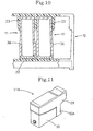
partition walls 23 may be formed on the upper wall portion of thehead holder 10. In this case, the width of the lower portion of eachink cartridge 11 is set to be larger than the width of the upper portion, whereby the same effect as the above embodiment can be obtained. - Still further, according to a fifth embodiment, shown in Figs. 11 and 12, a pair of side walls of a portion at the rear side of the lower portion of each
ink cartridge 11, that is, aportion 30A located at the rear side of thepartition walls 23, may be formed to be wider outwardly so that the width of theportion 30A is substantially equal to (is not necessary to be equal to) the width L1 of theupper portion 29. With this structure, as is apparent from Fig. 12, theink cartridge 11 can be prevented from being mounted on thehead holder 10 even when theink cartridge 11 is mounted with its front and rear portions being inverted to each other. In this case, no projection portion functioning as a grasp member is provided at the upper portion of the rear surface of thecartridge 11. In the case where no projection portion functioning as a grasp member is provided, or a short projection portion is provided, the rear surface wall of thecartridge 11 which is being mounted with its front and rear portion being inverted may abut against themesh filter 27 secured to the tip of theink supply member 26 and damage themesh filter 27. However, the above can be effectively prevented by the structure of the fifth embodiment. - There may be provided an ink cartridge which is detachably mounted on a head and designed in a substantially rectangular parallelepiped shape, comprising an upper portion having a first width and a lower portion having a second width different from the first width of said upper portion.
- The ink cartridge may further comprise an ink tank which is designed in a substantially rectangular parallelepiped shape so as to have an opening at one of the upper and lower portions thereof, a lid member which is adhesively attached to the peripheral edge of the opening and serves to close said ink tank and wherein the width of said ink tank at the portion having the opening is set to be larger than that of the other portion, and a pair of side walls which confront each other in the width direction of said ink tank are designed so as to have a smaller thickness at the portion having the smaller width.
- The inner wall surfaces of the pair of the side walls confronting each other in the width direction of said ink tank may be designed to be flat.
- The lid may adhere to said ink tank through a shear weld.
- A pair of opposing side walls may have an equal thickness which is uniform through the upper portion and the lower portion.
- There may be provided an ink cartridge that is removably mounted to a print head, comprising a body having five contiguous sides including a base side, a print end side, an opposite end side, a first lateral side and a second lateral side; and a cover side mounted to upper ends of the print end side, the opposite end side and the first and the second lateral sides to complete the body and define an ink chamber within the completed body, wherein each of the first and second lateral sides have a first portion and a second portion, a first distance from an outer surface of the first portion of the first lateral side to an outer surface of the first portion of the second lateral side is greater than a second distance from an outer surface of the second portion of the first lateral side to the outer surface of the second portion of the second lateral side.
- The first distance may be adjacent to the cover side.
- The first lateral side may have a uniform thickness and the first portion of the second lateral side may have a greater thickness than the second portion of the second lateral side.
- The ink cartridge may further comprise a print opening in the print end side.
- An inner surface of at least one of the first lateral side and the second lateral side may define a plane.
- An inner surface of the first lateral side may be parallel to an outer surface of the first lateral side and an inner surface of the second lateral side may be parallel to an outer surface of the second lateral side.
- A thickness of the first and second lateral sides may be substantially uniform throughout.
- An inner surface of the first lateral side may be parallel to the outer surface of the first lateral side, and an inner surface at the second portion of the second lateral side may be parallel to the outer surface at the second portion of the second lateral side and an inner surface of the first portion of the second lateral side may be parallel to the outer surface at the first portion of the second lateral side, the surfaces at the first and second portions not lying in the same plane.
- A thickness of the second lateral side at the second portion may be greater than a thickness of the second lateral side at the first portion.
- An open end of the print end side, the opposite end side, the first lateral side and the second lateral side may have a stepped wall and the cover side may have a stepped surface to correspond complimentary to the stepped wall for joining the cover side to the print end side, the opposite end side, and the first and second lateral sides.
- The body may further comprise a semi-circular projection which projects from the opposite end side of the body to engage the print head.
each ink cartridge including:
Claims (2)
- An ink printing device comprising:wherein the head holder (10) includes an ink-supply-member wall (25) that has ink supply members (26) for supplying ink from the ink cartridges (11A, 11B, 11C, 11D) to the inkjet head (21) and other walls that are contiguous with and extend angularly away from a peripheral edge of the ink-supply-member wall (25), the ink-supply-member wall (25) and the other walls forming a substantial open box shape defining an inner space and having an open side located opposite from the ink-supply-member wall (25), the other walls including a pair of side walls (24), a part of the inner space being sectioned by partition walls (23) parallel with the side walls (24) and provided on one of the other walls, the part of the inner space defining cartridge mounting portions (22A, 22B, . 22C, 22D) between partition walls (23) and between each side wall (24) and the partition wall (23) adjacent to the side wall (24) respectively, each partition wall (23) extending into the inner space in a direction between the ink-supply-member wall (25) and the open side, the cartridge mounting portions (22A, 22B, 22C, 22D) being open on the open side, each ink cartridge (11A, 11B, 11C, 11D) being independently formed for each ink and individually mounted in each cartridge mounting portions (22A, 22B, 22C, 22D); anda carriage (5);a head holder (10) mounted to the carriage (5);an ink jet head (21) mounted to the head holder (10); andink cartridges (11A, 11B, 11C, 11D) removably mounted to the ink jet holder (10) to engage with the ink jet head (21);
each ink cartridge (11A, 11B, 11C, 11D) including:an ink supply port (33) for connecting to the ink supply member (26) when the ink cartridge (11A, 11B, 11C, 11D) is mounted in one of the cartridge mounting portions (22A, 22B, 22C, 22D);a pair of lateral walls parallel to partition walls;a sandwiched portion (30) partly formed by one portion of the pair of lateral walls inserted between the partition walls (23) and between each side wall (24) and the partition wall (23) adjacent to the side wall (24) when the ink cartridge (11A, 11B, 11C, 11D) is mounted in the cartridge mounting portion (22A, 22B, 22C, 22D); anda wall-outside portion (29) partly formed by the other portion of the pair of lateral walls located outside the partition walls (23) when the ink cartridge (11 A, 11B, 11C, 11D) is mounted in the cartridge mounting portion (22A, 22B, 22C, 22D), the wall-outside portion (29) having a larger width (L1) than a distance between inner surfaces of the partition walls (23) confronting each other and between inner surfaces of each side wall (24) and the partition wall (23) adjacent to the side wall (24) confronting each other, wherein when the ink cartridges (11A, 11B, 11C, 11D) are mounted in the cartridge mounting portions (22A, 22B, 22C, 22D) respectively, the wall-outside portions (29) of the adjacent ink cartridges (11A, 11B, 11C, 11D) protrude toward each other outside the partition walls (23). - An ink printing device as claimed in claim 1, wherein each ink cartridge (11A, 11B, 11C, 11D) includes;
an ink tank having an opening at a portion thereof that corresponds to the wall-outside portion; and
a lid (35) mounted at a terminal edge of the opening to cover the opening in the ink tank;
wherein walls of the ink cartridge are thinner at the sandwiched portion (29) than at the wall-outside portion (29).
Applications Claiming Priority (3)
| Application Number | Priority Date | Filing Date | Title |
|---|---|---|---|
| JP21666995 | 1995-08-01 | ||
| JP21666995A JP3280202B2 (en) | 1995-08-01 | 1995-08-01 | Inkjet printer |
| EP96305635A EP0756936B1 (en) | 1995-08-01 | 1996-07-31 | Ink cartridge |
Related Parent Applications (1)
| Application Number | Title | Priority Date | Filing Date |
|---|---|---|---|
| EP96305635A Division EP0756936B1 (en) | 1995-08-01 | 1996-07-31 | Ink cartridge |
Publications (2)
| Publication Number | Publication Date |
|---|---|
| EP1219445A1 EP1219445A1 (en) | 2002-07-03 |
| EP1219445B1 true EP1219445B1 (en) | 2005-11-30 |
Family
ID=16692074
Family Applications (2)
| Application Number | Title | Priority Date | Filing Date |
|---|---|---|---|
| EP02006452A Expired - Lifetime EP1219445B1 (en) | 1995-08-01 | 1996-07-31 | Ink cartridge |
| EP96305635A Expired - Lifetime EP0756936B1 (en) | 1995-08-01 | 1996-07-31 | Ink cartridge |
Family Applications After (1)
| Application Number | Title | Priority Date | Filing Date |
|---|---|---|---|
| EP96305635A Expired - Lifetime EP0756936B1 (en) | 1995-08-01 | 1996-07-31 | Ink cartridge |
Country Status (6)
| Country | Link |
|---|---|
| US (1) | US5886720A (en) |
| EP (2) | EP1219445B1 (en) |
| JP (1) | JP3280202B2 (en) |
| CN (1) | CN1141849A (en) |
| AU (1) | AU713867B2 (en) |
| DE (2) | DE69635532T2 (en) |
Families Citing this family (16)
| Publication number | Priority date | Publication date | Assignee | Title |
|---|---|---|---|---|
| JP3479392B2 (en) * | 1995-08-01 | 2003-12-15 | ブラザー工業株式会社 | Connection structure of ink cartridge |
| DE69839102T2 (en) * | 1997-03-03 | 2009-02-05 | Seiko Epson Corp. | inkjet |
| USD424103S (en) * | 1999-02-18 | 2000-05-02 | Hewlett-Packard Company | Inkjet printhead |
| USD419593S (en) * | 1997-12-25 | 2000-01-25 | Canon Kabushiki Kaisha | Ink tank for printer |
| JP3706776B2 (en) * | 1998-09-03 | 2005-10-19 | キヤノン株式会社 | Ink tank, tank holder, inkjet head cartridge, and inkjet recording apparatus |
| JP2000127424A (en) * | 1998-10-27 | 2000-05-09 | Canon Inc | Liquid container and cap therefor |
| JP2001010078A (en) * | 1999-04-27 | 2001-01-16 | Canon Inc | Ink tank, holder with the ink tank mounted, ink-jet recording apparatus provided with the holder, and method for mounting ink tank to holder |
| JP2001010081A (en) * | 1999-06-30 | 2001-01-16 | Canon Inc | Ink jet cartridge, ink jet device and manufacture of ink jet cartridge |
| US6264313B1 (en) * | 1999-09-10 | 2001-07-24 | Nypro, Inc. | Fluid delivery manifold and method of manufacturing the same |
| US6290346B1 (en) | 2000-01-05 | 2001-09-18 | Hewlett-Packard Company | Multiple bit matrix configuration for key-latched printheads |
| US6499826B1 (en) | 2000-01-05 | 2002-12-31 | Hewlett-Packard Company | Horizontally loadable carriage for an ink-jet printer |
| JP3770315B2 (en) * | 2000-12-25 | 2006-04-26 | セイコーエプソン株式会社 | ink cartridge |
| US6779874B2 (en) * | 2001-07-31 | 2004-08-24 | Hewlett-Packard Development Company, Lp. | Device for ensuring proper toe-heel installation of a detachable printer component |
| JP4479638B2 (en) * | 2005-09-29 | 2010-06-09 | ブラザー工業株式会社 | ink cartridge |
| US7284848B2 (en) | 2005-11-28 | 2007-10-23 | Brother Kogyo Kabushiki Kaisha | Ink cartridges |
| JP6028425B2 (en) * | 2012-07-06 | 2016-11-16 | セイコーエプソン株式会社 | Cartridge and printing device |
Family Cites Families (14)
| Publication number | Priority date | Publication date | Assignee | Title |
|---|---|---|---|---|
| DE2812562C2 (en) * | 1978-03-22 | 1983-09-08 | Siemens AG, 1000 Berlin und 8000 München | Device for optionally shutting off the flow of ink in ink typing devices of office, data or teletyping machines |
| DE7833494U1 (en) * | 1978-11-10 | 1980-04-17 | Siemens Ag, 1000 Berlin Und 8000 Muenchen | BOTTLE FOR WRITING LIQUID |
| IT1179973B (en) * | 1984-02-15 | 1987-09-23 | Olivetti & Co Spa | SELECTIVE JET INK PRINT HEAD AND INK CARTRIDGE FOR SUCH HEAD |
| JPS6357243A (en) * | 1986-08-28 | 1988-03-11 | Toshiba Corp | Recorder |
| JP3066867B2 (en) * | 1988-10-31 | 2000-07-17 | キヤノン株式会社 | Inkjet printer, recording head, ink cassette and sales set for inkjet recording |
| US5488401A (en) * | 1991-01-18 | 1996-01-30 | Seiko Epson Corporation | Ink-jet recording apparatus and ink tank cartridge thereof |
| US5199470B1 (en) * | 1991-05-17 | 1996-05-14 | Graphic Utilities Inc | Method and apparatus for refilling ink cartridges |
| JP2962044B2 (en) * | 1992-05-29 | 1999-10-12 | 富士ゼロックス株式会社 | Ink tank, inkjet cartridge, and inkjet recording device |
| US5509140A (en) * | 1992-07-24 | 1996-04-16 | Canon Kabushiki Kaisha | Replaceable ink cartridge |
| CA2272160C (en) * | 1992-07-31 | 2003-10-14 | Canon Kabushiki Kaisha | Liquid storing container for recording apparatus |
| US5408746A (en) * | 1993-04-30 | 1995-04-25 | Hewlett-Packard Company | Datum formation for improved alignment of multiple nozzle members in a printer |
| JP3133906B2 (en) * | 1993-08-19 | 2001-02-13 | キヤノン株式会社 | Ink tank cartridge |
| US5619239A (en) * | 1993-11-29 | 1997-04-08 | Canon Kabushiki Kaisha | Replaceable ink tank |
| JP3253206B2 (en) * | 1994-01-14 | 2002-02-04 | キヤノン株式会社 | Ink filling method |
-
1995
- 1995-08-01 JP JP21666995A patent/JP3280202B2/en not_active Expired - Lifetime
-
1996
- 1996-04-23 US US08/636,690 patent/US5886720A/en not_active Expired - Lifetime
- 1996-07-31 EP EP02006452A patent/EP1219445B1/en not_active Expired - Lifetime
- 1996-07-31 AU AU60845/96A patent/AU713867B2/en not_active Ceased
- 1996-07-31 DE DE69635532T patent/DE69635532T2/en not_active Expired - Lifetime
- 1996-07-31 DE DE69624298T patent/DE69624298T2/en not_active Expired - Lifetime
- 1996-07-31 EP EP96305635A patent/EP0756936B1/en not_active Expired - Lifetime
- 1996-08-01 CN CN96112242A patent/CN1141849A/en active Pending
Also Published As
| Publication number | Publication date |
|---|---|
| AU6084596A (en) | 1997-02-06 |
| EP0756936A2 (en) | 1997-02-05 |
| EP0756936A3 (en) | 1997-08-13 |
| AU713867B2 (en) | 1999-12-09 |
| EP1219445A1 (en) | 2002-07-03 |
| CN1141849A (en) | 1997-02-05 |
| US5886720A (en) | 1999-03-23 |
| DE69635532T2 (en) | 2006-08-10 |
| DE69624298T2 (en) | 2003-02-27 |
| EP0756936B1 (en) | 2002-10-16 |
| DE69624298D1 (en) | 2002-11-21 |
| JPH0939266A (en) | 1997-02-10 |
| DE69635532D1 (en) | 2006-01-05 |
| JP3280202B2 (en) | 2002-04-30 |
Similar Documents
| Publication | Publication Date | Title |
|---|---|---|
| EP1219445B1 (en) | Ink cartridge | |
| EP2292431B1 (en) | Liquid container, methods of assembling or disassembling liquid container, and image forming apparatus | |
| EP1403064B1 (en) | Ink container, recording head and recording device using same | |
| US5534899A (en) | Replaceable ink tank | |
| EP1567354B1 (en) | Ink cartridge, housing therefor, ink bag, ink-jet recording apparatus, ink container, and image-forming apparatus | |
| EP0604128B1 (en) | Ink jet cartridge | |
| EP1095777B1 (en) | Ink cartridge for use in an ink jet recording apparatus | |
| US6070975A (en) | Ink jet recording apparatus and a method for installing ink jet recording head | |
| EP0908317B1 (en) | Ink jet cartridge having replaceable ink supply tanks with an internal filter | |
| JP3188056B2 (en) | Ink jet recording device and ink jet head | |
| JP2011088450A (en) | Ink cartridge holder | |
| JP3155081B2 (en) | Ink jet recording device | |
| JP3479392B2 (en) | Connection structure of ink cartridge | |
| JPH07179004A (en) | Ink jet head cartridge and ink jet recording device | |
| JPH07304190A (en) | Liquid jet recording device | |
| JP3692609B2 (en) | Inkjet recording device | |
| US7500738B2 (en) | Ink cartridge | |
| JP3241941B2 (en) | Inkjet cartridge storage container | |
| JP2002225314A (en) | Ink jet recorder | |
| JPH09156126A (en) | Ink jet printer | |
| JPH06312515A (en) | Ink jet recording device | |
| JP2004249710A (en) | Ink tank, and recording head using the same and recording apparatus | |
| JPH09286119A (en) | Ink jet recorder | |
| JPH03183553A (en) | Ink jet recording head assembly and recorder mounting it | |
| JPH08300676A (en) | Ink cartridge and recording apparatus |
Legal Events
| Date | Code | Title | Description |
|---|---|---|---|
| PUAI | Public reference made under article 153(3) epc to a published international application that has entered the european phase |
Free format text: ORIGINAL CODE: 0009012 |
|
| AC | Divisional application: reference to earlier application |
Ref document number: 756936 Country of ref document: EP |
|
| AK | Designated contracting states |
Kind code of ref document: A1 Designated state(s): CH DE FR GB LI |
|
| 17P | Request for examination filed |
Effective date: 20021218 |
|
| AKX | Designation fees paid |
Designated state(s): CH DE FR GB LI |
|
| 17Q | First examination report despatched |
Effective date: 20040121 |
|
| GRAP | Despatch of communication of intention to grant a patent |
Free format text: ORIGINAL CODE: EPIDOSNIGR1 |
|
| GRAS | Grant fee paid |
Free format text: ORIGINAL CODE: EPIDOSNIGR3 |
|
| GRAA | (expected) grant |
Free format text: ORIGINAL CODE: 0009210 |
|
| AC | Divisional application: reference to earlier application |
Ref document number: 0756936 Country of ref document: EP Kind code of ref document: P |
|
| AK | Designated contracting states |
Kind code of ref document: B1 Designated state(s): CH DE FR GB LI |
|
| PG25 | Lapsed in a contracting state [announced via postgrant information from national office to epo] |
Ref country code: LI Free format text: LAPSE BECAUSE OF FAILURE TO SUBMIT A TRANSLATION OF THE DESCRIPTION OR TO PAY THE FEE WITHIN THE PRESCRIBED TIME-LIMIT Effective date: 20051130 Ref country code: CH Free format text: LAPSE BECAUSE OF FAILURE TO SUBMIT A TRANSLATION OF THE DESCRIPTION OR TO PAY THE FEE WITHIN THE PRESCRIBED TIME-LIMIT Effective date: 20051130 |
|
| REG | Reference to a national code |
Ref country code: GB Ref legal event code: FG4D Ref country code: CH Ref legal event code: EP |
|
| REF | Corresponds to: |
Ref document number: 69635532 Country of ref document: DE Date of ref document: 20060105 Kind code of ref document: P |
|
| REG | Reference to a national code |
Ref country code: CH Ref legal event code: PL |
|
| ET | Fr: translation filed | ||
| PLBE | No opposition filed within time limit |
Free format text: ORIGINAL CODE: 0009261 |
|
| STAA | Information on the status of an ep patent application or granted ep patent |
Free format text: STATUS: NO OPPOSITION FILED WITHIN TIME LIMIT |
|
| 26N | No opposition filed |
Effective date: 20060831 |
|
| REG | Reference to a national code |
Ref country code: FR Ref legal event code: PLFP Year of fee payment: 20 |
|
| PGFP | Annual fee paid to national office [announced via postgrant information from national office to epo] |
Ref country code: GB Payment date: 20150624 Year of fee payment: 20 |
|
| PGFP | Annual fee paid to national office [announced via postgrant information from national office to epo] |
Ref country code: FR Payment date: 20150624 Year of fee payment: 20 |
|
| PGFP | Annual fee paid to national office [announced via postgrant information from national office to epo] |
Ref country code: DE Payment date: 20150731 Year of fee payment: 20 |
|
| REG | Reference to a national code |
Ref country code: DE Ref legal event code: R071 Ref document number: 69635532 Country of ref document: DE |
|
| REG | Reference to a national code |
Ref country code: GB Ref legal event code: PE20 Expiry date: 20160730 |
|
| PG25 | Lapsed in a contracting state [announced via postgrant information from national office to epo] |
Ref country code: GB Free format text: LAPSE BECAUSE OF EXPIRATION OF PROTECTION Effective date: 20160730 |