EP0756856B1 - Wheelchair - Google Patents
Wheelchair Download PDFInfo
- Publication number
- EP0756856B1 EP0756856B1 EP96112283A EP96112283A EP0756856B1 EP 0756856 B1 EP0756856 B1 EP 0756856B1 EP 96112283 A EP96112283 A EP 96112283A EP 96112283 A EP96112283 A EP 96112283A EP 0756856 B1 EP0756856 B1 EP 0756856B1
- Authority
- EP
- European Patent Office
- Prior art keywords
- driving
- driving force
- motor
- force
- handle
- Prior art date
- Legal status (The legal status is an assumption and is not a legal conclusion. Google has not performed a legal analysis and makes no representation as to the accuracy of the status listed.)
- Expired - Lifetime
Links
Images





Classifications
-
- A—HUMAN NECESSITIES
- A61—MEDICAL OR VETERINARY SCIENCE; HYGIENE
- A61G—TRANSPORT, PERSONAL CONVEYANCES, OR ACCOMMODATION SPECIALLY ADAPTED FOR PATIENTS OR DISABLED PERSONS; OPERATING TABLES OR CHAIRS; CHAIRS FOR DENTISTRY; FUNERAL DEVICES
- A61G5/00—Chairs or personal conveyances specially adapted for patients or disabled persons, e.g. wheelchairs
- A61G5/04—Chairs or personal conveyances specially adapted for patients or disabled persons, e.g. wheelchairs motor-driven
- A61G5/041—Chairs or personal conveyances specially adapted for patients or disabled persons, e.g. wheelchairs motor-driven having a specific drive-type
- A61G5/045—Rear wheel drive
-
- A—HUMAN NECESSITIES
- A61—MEDICAL OR VETERINARY SCIENCE; HYGIENE
- A61G—TRANSPORT, PERSONAL CONVEYANCES, OR ACCOMMODATION SPECIALLY ADAPTED FOR PATIENTS OR DISABLED PERSONS; OPERATING TABLES OR CHAIRS; CHAIRS FOR DENTISTRY; FUNERAL DEVICES
- A61G5/00—Chairs or personal conveyances specially adapted for patients or disabled persons, e.g. wheelchairs
- A61G5/04—Chairs or personal conveyances specially adapted for patients or disabled persons, e.g. wheelchairs motor-driven
- A61G5/048—Power-assistance activated by pushing on hand rim or on handlebar
-
- A—HUMAN NECESSITIES
- A61—MEDICAL OR VETERINARY SCIENCE; HYGIENE
- A61G—TRANSPORT, PERSONAL CONVEYANCES, OR ACCOMMODATION SPECIALLY ADAPTED FOR PATIENTS OR DISABLED PERSONS; OPERATING TABLES OR CHAIRS; CHAIRS FOR DENTISTRY; FUNERAL DEVICES
- A61G5/00—Chairs or personal conveyances specially adapted for patients or disabled persons, e.g. wheelchairs
- A61G5/10—Parts, details or accessories
- A61G5/1005—Wheelchairs having brakes
- A61G5/1032—Wheelchairs having brakes engaging an element of the drive or transmission, e.g. drive belt, electrodynamic brake
-
- A—HUMAN NECESSITIES
- A61—MEDICAL OR VETERINARY SCIENCE; HYGIENE
- A61G—TRANSPORT, PERSONAL CONVEYANCES, OR ACCOMMODATION SPECIALLY ADAPTED FOR PATIENTS OR DISABLED PERSONS; OPERATING TABLES OR CHAIRS; CHAIRS FOR DENTISTRY; FUNERAL DEVICES
- A61G5/00—Chairs or personal conveyances specially adapted for patients or disabled persons, e.g. wheelchairs
- A61G5/10—Parts, details or accessories
- A61G5/1054—Large wheels, e.g. higher than the seat portion
-
- B—PERFORMING OPERATIONS; TRANSPORTING
- B60—VEHICLES IN GENERAL
- B60K—ARRANGEMENT OR MOUNTING OF PROPULSION UNITS OR OF TRANSMISSIONS IN VEHICLES; ARRANGEMENT OR MOUNTING OF PLURAL DIVERSE PRIME-MOVERS IN VEHICLES; AUXILIARY DRIVES FOR VEHICLES; INSTRUMENTATION OR DASHBOARDS FOR VEHICLES; ARRANGEMENTS IN CONNECTION WITH COOLING, AIR INTAKE, GAS EXHAUST OR FUEL SUPPLY OF PROPULSION UNITS IN VEHICLES
- B60K26/00—Arrangement or mounting of propulsion-unit control devices in vehicles
- B60K26/02—Arrangement or mounting of propulsion-unit control devices in vehicles of initiating means or elements
-
- B—PERFORMING OPERATIONS; TRANSPORTING
- B60—VEHICLES IN GENERAL
- B60K—ARRANGEMENT OR MOUNTING OF PROPULSION UNITS OR OF TRANSMISSIONS IN VEHICLES; ARRANGEMENT OR MOUNTING OF PLURAL DIVERSE PRIME-MOVERS IN VEHICLES; AUXILIARY DRIVES FOR VEHICLES; INSTRUMENTATION OR DASHBOARDS FOR VEHICLES; ARRANGEMENTS IN CONNECTION WITH COOLING, AIR INTAKE, GAS EXHAUST OR FUEL SUPPLY OF PROPULSION UNITS IN VEHICLES
- B60K7/00—Disposition of motor in, or adjacent to, traction wheel
- B60K7/0007—Disposition of motor in, or adjacent to, traction wheel the motor being electric
-
- A—HUMAN NECESSITIES
- A61—MEDICAL OR VETERINARY SCIENCE; HYGIENE
- A61G—TRANSPORT, PERSONAL CONVEYANCES, OR ACCOMMODATION SPECIALLY ADAPTED FOR PATIENTS OR DISABLED PERSONS; OPERATING TABLES OR CHAIRS; CHAIRS FOR DENTISTRY; FUNERAL DEVICES
- A61G2203/00—General characteristics of devices
- A61G2203/10—General characteristics of devices characterised by specific control means, e.g. for adjustment or steering
- A61G2203/14—Joysticks
-
- A—HUMAN NECESSITIES
- A61—MEDICAL OR VETERINARY SCIENCE; HYGIENE
- A61G—TRANSPORT, PERSONAL CONVEYANCES, OR ACCOMMODATION SPECIALLY ADAPTED FOR PATIENTS OR DISABLED PERSONS; OPERATING TABLES OR CHAIRS; CHAIRS FOR DENTISTRY; FUNERAL DEVICES
- A61G5/00—Chairs or personal conveyances specially adapted for patients or disabled persons, e.g. wheelchairs
- A61G5/10—Parts, details or accessories
- A61G5/1005—Wheelchairs having brakes
- A61G5/1008—Wheelchairs having brakes for gradually slowing down the wheelchair
-
- A—HUMAN NECESSITIES
- A61—MEDICAL OR VETERINARY SCIENCE; HYGIENE
- A61G—TRANSPORT, PERSONAL CONVEYANCES, OR ACCOMMODATION SPECIALLY ADAPTED FOR PATIENTS OR DISABLED PERSONS; OPERATING TABLES OR CHAIRS; CHAIRS FOR DENTISTRY; FUNERAL DEVICES
- A61G5/00—Chairs or personal conveyances specially adapted for patients or disabled persons, e.g. wheelchairs
- A61G5/10—Parts, details or accessories
- A61G5/1005—Wheelchairs having brakes
- A61G5/1037—Wheelchairs having brakes manipulated by assisting person
-
- B—PERFORMING OPERATIONS; TRANSPORTING
- B60—VEHICLES IN GENERAL
- B60K—ARRANGEMENT OR MOUNTING OF PROPULSION UNITS OR OF TRANSMISSIONS IN VEHICLES; ARRANGEMENT OR MOUNTING OF PLURAL DIVERSE PRIME-MOVERS IN VEHICLES; AUXILIARY DRIVES FOR VEHICLES; INSTRUMENTATION OR DASHBOARDS FOR VEHICLES; ARRANGEMENTS IN CONNECTION WITH COOLING, AIR INTAKE, GAS EXHAUST OR FUEL SUPPLY OF PROPULSION UNITS IN VEHICLES
- B60K17/00—Arrangement or mounting of transmissions in vehicles
- B60K17/04—Arrangement or mounting of transmissions in vehicles characterised by arrangement, location or kind of gearing
- B60K17/043—Transmission unit disposed in on near the vehicle wheel, or between the differential gear unit and the wheel
-
- B—PERFORMING OPERATIONS; TRANSPORTING
- B60—VEHICLES IN GENERAL
- B60K—ARRANGEMENT OR MOUNTING OF PROPULSION UNITS OR OF TRANSMISSIONS IN VEHICLES; ARRANGEMENT OR MOUNTING OF PLURAL DIVERSE PRIME-MOVERS IN VEHICLES; AUXILIARY DRIVES FOR VEHICLES; INSTRUMENTATION OR DASHBOARDS FOR VEHICLES; ARRANGEMENTS IN CONNECTION WITH COOLING, AIR INTAKE, GAS EXHAUST OR FUEL SUPPLY OF PROPULSION UNITS IN VEHICLES
- B60K7/00—Disposition of motor in, or adjacent to, traction wheel
- B60K2007/0046—Disposition of motor in, or adjacent to, traction wheel the motor moving together with the vehicle body, i.e. moving independently from the wheel axle
-
- B—PERFORMING OPERATIONS; TRANSPORTING
- B60—VEHICLES IN GENERAL
- B60K—ARRANGEMENT OR MOUNTING OF PROPULSION UNITS OR OF TRANSMISSIONS IN VEHICLES; ARRANGEMENT OR MOUNTING OF PLURAL DIVERSE PRIME-MOVERS IN VEHICLES; AUXILIARY DRIVES FOR VEHICLES; INSTRUMENTATION OR DASHBOARDS FOR VEHICLES; ARRANGEMENTS IN CONNECTION WITH COOLING, AIR INTAKE, GAS EXHAUST OR FUEL SUPPLY OF PROPULSION UNITS IN VEHICLES
- B60K7/00—Disposition of motor in, or adjacent to, traction wheel
- B60K2007/0061—Disposition of motor in, or adjacent to, traction wheel the motor axle being parallel to the wheel axle
-
- B—PERFORMING OPERATIONS; TRANSPORTING
- B60—VEHICLES IN GENERAL
- B60L—PROPULSION OF ELECTRICALLY-PROPELLED VEHICLES; SUPPLYING ELECTRIC POWER FOR AUXILIARY EQUIPMENT OF ELECTRICALLY-PROPELLED VEHICLES; ELECTRODYNAMIC BRAKE SYSTEMS FOR VEHICLES IN GENERAL; MAGNETIC SUSPENSION OR LEVITATION FOR VEHICLES; MONITORING OPERATING VARIABLES OF ELECTRICALLY-PROPELLED VEHICLES; ELECTRIC SAFETY DEVICES FOR ELECTRICALLY-PROPELLED VEHICLES
- B60L2220/00—Electrical machine types; Structures or applications thereof
- B60L2220/40—Electrical machine applications
- B60L2220/46—Wheel motors, i.e. motor connected to only one wheel
-
- B—PERFORMING OPERATIONS; TRANSPORTING
- B60—VEHICLES IN GENERAL
- B60Y—INDEXING SCHEME RELATING TO ASPECTS CROSS-CUTTING VEHICLE TECHNOLOGY
- B60Y2200/00—Type of vehicle
- B60Y2200/80—Other vehicles not covered by groups B60Y2200/10 - B60Y2200/60
- B60Y2200/84—Wheelchairs
-
- Y—GENERAL TAGGING OF NEW TECHNOLOGICAL DEVELOPMENTS; GENERAL TAGGING OF CROSS-SECTIONAL TECHNOLOGIES SPANNING OVER SEVERAL SECTIONS OF THE IPC; TECHNICAL SUBJECTS COVERED BY FORMER USPC CROSS-REFERENCE ART COLLECTIONS [XRACs] AND DIGESTS
- Y10—TECHNICAL SUBJECTS COVERED BY FORMER USPC
- Y10S—TECHNICAL SUBJECTS COVERED BY FORMER USPC CROSS-REFERENCE ART COLLECTIONS [XRACs] AND DIGESTS
- Y10S180/00—Motor vehicles
- Y10S180/907—Motorized wheelchairs
Definitions
- the present invention relates to a wheelchair. More particularly, the present invention relates to an assisted wheelchair having a driving wheel.
- assisted wheelchairs having a driving wheel.
- One type thereof is a manually-operated assisted wheelchair having a handle for transmitting the human driving force generated by pushing or pulling operation of an assistant to a driving wheel to propel the main body, the wheelchair being intended to be run by the human power of the assistant.
- the other type is an electrically-operated assisted wheelchair having a driving motor, a decelerator, and a battery for power supply, the wheelchair being intended to be run electrically by the motor.
- the manually-operated assisted wheelchair is a wheelchair run by rotation of a driving wheel generated by the assistant's operation of a handle with a hand. Therefore, it is necessary to employ a labor of operating the handle, so that the assistant is liable to get tired when one wants to go for a long distance or when the wheelchair is used on an upward slope, thus rendering the use thereof difficult.
- the electrically-operated wheelchair is considerably heavy and large-sized because of a large capacity battery which the wheelchair carries, so that it has been extremely difficult to load the wheelchair on an automobile or a truck. Also, since the turning radius is large contrary to the manually-operated assisted wheelchair, the electrically-operated assisted wheelchair cannot turn in a small circle, so that the use in a small space such as in a room has been restricted.
- the present invention has been made in view of the above circumstances and the main purpose thereof is to provide a comparatively less heavy and small-sized assisted wheelchair that does not need so much manual labor of the assistant's handle operation.
- WO 95/05141 discloses a wheelchair as claimed in the preamble of claim 1.
- the present invention provides a wheelchair comprising a main body having a seat for a user and a driving wheel, a handle provided in the main body for propelling the main body by a human driving force of an assistant, a motor for auxiliarily driving the driving wheel by an electric driving force, and a battery for supplying a power to the motor, a handle driving-force detector for detecting the human driving force applied to the handle, and a controller for controlling the motor reflecting a result of the detection by the handle driving-force detector, whereby the electric driving force can be added to the driving wheel in accordance with the human driving force applied to the handle.
- a changeover switch is also provided for changing the operaton/non-operation of the motor and the flat land or downward slope travelling/upward slope travelling, based on a judgement of the user or the assistant.
- Fig. 1 is a side view showing an overall outlook of a wheelchair according to an embodiment of the present invention.
- Fig. 2 is a plan view showing the wheelchair of Fig. 1.
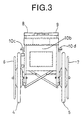
- Fig. 3 is a rear view showing the wheelchair of Fig. 1.
- Fig. 4 is a perspective view showing a battery portion which is a constituting member of the wheelchair of Fig. 1.
- Fig. 5 is a plan view showing a changeover switch which is a constituting member of the wheelchair of Fig. 1.
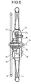
- Fig. 6 is a rear sectional view showing a casing which is a constituting member of the wheelchair of Fig. 1.
- Fig. 7 is a side view showing the inside of the casing of Fig. 6.
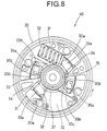
- Fig. 8 is a side view showing a handrim driving-force detector disposed inside the casing of Fig. 6.
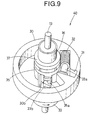
- Fig. 9 is a perspective view showing the handrim driving-force detector of Fig. 8.
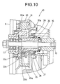
- Fig. 10 is a rear sectional view showing the handrim driving-force detector of Fig. 8.
- Fig. 11 is a plan view showing a handle driving-force detector disposed on the upper rear portion of the frame assembly in the wheelchair of Fig. 1.
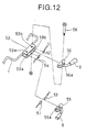
- Fig. 12 is an exploded perspective view showing the handle driving-force detector of Fig. 11.
- the main body of the wheelchair generally comprises a frame assembly.
- the frame assembly comprises a right frame, a left frame, and a cross rod.
- the user seat may be formed integrally or non-integrally with the frame assembly.
- the driving wheel may be either a front wheel or a rear wheel as long as the human driving force of the assistant constituting the main driving force of the wheelchair can be transmitted to the driving wheel.
- a pair of front wheels are provided as casters
- a pair of rear wheels are provided as driving wheels.
- the handle is mounted, for example, in a pair on right and left sides of the upper rear portion of the main body, i.e. the frame assembly, so as to transmit to the main driving wheel the human driving force based on the pushing or pulling operation of the assistant's hand (a forward pushing operation or a backward pulling operation) to propel the main body.
- the motor is provided so as to auxiliarily drive the driving wheel. Namely, when a certain amount of human driving force is applied to the driving wheel from the handle by the assistant, the motor operates to apply an electric driving force to the driving wheel at a predetermined ratio.
- the motor usually comprises a decelerator.
- a combination of a pulley and a belt, a combination of decelerating gears, or both may be used as the decelerator.
- an element mainly consisting of a combination of a pulley and a belt In order to suppress the noise, it is preferable to use an element mainly consisting of a combination of a pulley and a belt.
- the battery for power supply may be an element comprising a battery such as a rechargeable dry battery, a rechargeable storage battery, or a non-rechargeable dry battery and a case for housing a predetermined number of these batteries.
- the handle driving-force detector detects an amount of the human driving force applied to the handle.
- the handle driving-force detector may be, for example, an element comprising a pressure sensor detecting the amount of power for pushing the handle forward, an element comprising a pressure sensor detecting the amount of power for pulling the handle backward, or an element comprising a pressure sensor detecting the amount of power for pushing the handle forward and detecting the amount of power for pulling the handle backward.
- the controller mainly reflects an amount of the human driving force detected by the handle driving-force detector to control the motor.
- the controller may control the motor also in response to a rotation speed of the driving wheel or a travelling speed of the wheelchair which is detected by an appropriate means.
- the controller may be constructed to operate, for example, (a) so that the motor is controlled for applying a large or small electric driving force to the driving wheel depending on whether the detected human driving force is large or small, respectively; (b) so that the motor is controlled for applying the same amount of electric driving force to the driving wheel as the detected human driving force when a travelling speed of the wheelchair is within a certain range and for applying a smaller amount of electric driving force to the driving wheel than the detected human driving force when the travelling speed exceeds the above range; or (c) so that the motor is controlled for applying the electric driving force to the driving wheel depending on whether the wheelchair is travelling on a flat land or on a slope (an upward slope or a downward slope).
- the controller preferably has a function of directing the dynamoelectric braking to the motor depending on the result of the detection by the pressure sensor, namely, the amount of power for pulling the handle backward. If the controller has such a function, it is possible to direct a dynamoelectric braking to the motor to suppress the speed when the wheelchair is travelling on a downward slope or the like with the speed being increased and dangerous.
- the wheelchair according to the present invention further comprises a handrim provided integrally with the driving wheel for driving the driving wheel with the human driving force of a user and a handrim driving-force detector for detecting the human driving force applied to the handrim, the controller further having a function of controlling the motor reflecting the result of the detection by the handrim driving-force detector, whereby the electric driving force can be added to the driving wheel in accordance with the human driving force applied either to the handle or to the handrim.
- the handrim driving-force detector detects the amount of human driving force applied to the handrim.
- the handrim driving-force detector comprises an elastic body that contracts when a human driving force exceeding a predetermined amount is applied to the handrim and expands otherwise, a converting member for converting the amount of contraction or expansion of the elastic body into a shift amount along the longitudinal direction of a hub shaft of the driving wheel, and a detecting member for generating an electric output change in accordance with the shift amount of the converting member and for detecting the output.
- the controller has a function of controlling the motor reflecting the result of the detection by the handrim driving-force detector, whereby the electric driving force can be added to the driving wheel in accordance with the human driving force applied either to the handle or to the handrim.
- the controlling method may be (a), (b), or (c) in the above.
- Figs. 1 to 3 are views showing an outlook construction of the wheelchair D according to an embodiment of the present invention.
- the wheelchair D is mainly constructed with a frame assembly 1 which forms a main body, a pair of right and left casters (front wheels) 2 and 3 supported by the front portion of the frame assembly 1, a pair of right and left driving wheels (rear wheels) 4 and 5 supported by the rear portion of the frame assembly 1, a pair of right and left handrims 6 and 7 mounted to the driving wheels 4 and 5, respectively, for driving the driving wheels 4 and 5 by the human driving force of the user, a pair of right and left handles 8 and 9 provided on the upper rear portion of the frame assembly 1 for propelling the main body by transmitting a human driving force of an assistant which is a main driving force of the wheelchair D to the driving wheels 4 and 5, respectively, a seat unit 10 disposed in the central portion of the frame assembly 1 for the user, and a battery portion 11 disposed on the left side of the frame assembly 1 for power supply.
- a frame assembly 1 which forms a main body
- the seat unit 10 comprises a seat 10a, a backrest 10b, a pair of right and left armrests 10c and 10d, a pair of right and left footrests 10e and 10f, and others.
- the changeover switch 12 includes a first switch 12a for turning the power on and off to select whether the electric driving force is to be added to the driving wheels 4 and 5, and a second switch 12b for changing the ratio of the electric driving force to be added depending on whether the wheelchair D is travelling on a flat (level) land or downward slope, or travelling on an upward slope when the power is on, as shown also in Fig. 5.
- the hub shaft 13 of the driving wheel 4 is protected by a disk-like casing 14, as shown in Fig. 6.
- the casing 14 is divided into right and left portions.
- the right hand member of the divided casing 14 is fixed to the hub shaft 13 and serves as a fixed-side casing member 15.
- the left hand member of the divided casing 14 is mounted to the hub shell 16 covering the hub shaft 13, the left hand member being integral with the handrim 6 to serve as a rotative-side casing member 17 rotatable with the handrim 6 and the driving wheel 4.
- Fig. 7 shows an inner structure of the casing 14.
- a controller 20 including an electric circuit board 18, a radiator board 19, and others and a motor 21 for auxiliarily driving the driving wheel 4 are mounted on the fixed-side casing member 15.
- the rotation of the motor 21 is reducingly transmitted to a motor pulley 22 mounted on the motor shaft, a first belt 23, a first pulley 24 mounted on the fixed-side casing member 15 in the vicinity of the motor 21, a second pulley 25 disposed coaxially with the first pulley 24, a second belt 26, a third pulley 27 mounted on the fixed-side casing member 15 in the vicinity of the second pulley 25, a fourth pulley 28 disposed coaxially with the third pulley 27, a third belt 29, and a fifth pulley 30 (a final decelerating member) disposed integrally with the hub shell 16.
- the fifth pulley 30 rotates, the rotative-side casing member 17, the driving wheel 4, and the handrim 6 rotate together with the fifth pulley 30
- the structure and the function of the handrim driving-force detector 40 for detecting the human driving force applied to the handrim 6 will be explained referring to Figs. 8 to 10.
- the fifth pulley 30 at pointwise symmetrical positions with respect to the hub shaft 13, there are provided two recessed portions 31, 31 having a depth approximately the same as the thickness of the fifth pulley 30.
- the coil spring 32 is disposed with its expanding and contracting directions approximately parallel to the tangential direction of the hub shaft 13. One end of the coil spring 32 is allowed to abut against one end wall of the recessed portion 31, and the other end thereof serves as a free end.
- the reference numeral 33 represents a disk-like pressing operation board which serves as one element of the converting member constituting a portion of the driving force detector 40, the disk-like pressing operation board being integral with the handrim 6 and combined with the fifth pulley 30.
- the pressing operation board 33 has a pair of pressing portions 33a, 33a and a pair of operation portions 33b, 33b projecting to the fifth pulley 30 side at pointwise symmetrical positions with respect to the hub shaft 13.
- the pressing portion 33a and the operation portion 33b of the pressing operation board 33 are loosely fitted respectively into two approximately sectorial through-bores 30a and 30b formed in the fifth pulley 30 so that the pressing portion 33a and the operation portion 33b may be rotatable by a length of the circumference of the through-bores 30a and 30b.
- the pressing portion 33a is prismatic and, when the driving wheel 4 is at rest, a rounded side of the pressing portion 33a abuts against the free end of the coil spring 32 by an urging power of the coil spring 32, and the other square side of the pressing portion 33a abuts against a rubber board 34 mounted on the other end of the recessed portion 31 and serving as a cushioning member.
- the operation portion 33b is prismatic having a height lower than that of the pressing portion 33a.
- the upper surface of the operation portion 33b is formed so as to be downwardly inclined in the rotation direction shown by an arrow in Figs. 8 and 9 (the direction of the positive rotation of the handrim 6 and the pressing operation board 33).
- the pressing portion 33a presses the coil spring 32 to allow the pressing operation board 33 to rotate in the positive direction within a predetermined range (the range of the length of the circumference of the through-bores 30a and 30b) when the human driving force applied to the pressing operation board 33 from the handrim 6 in the positive direction (the forward direction) surpasses the urging force of the coil spring 32.
- the pressing operation board 33 may also rotate in accordance with the rotation of the fifth pulley 30.
- the reference numeral 35 represents a ring-like slide assembly which serves as the other element of the converting member constituting a portion of the driving force detector 40, the ring-like slide assembly being loosely fitted into the hub shell 16.
- a part of the slide assembly 35 is fitted to two guides 30c, 30c provided on the fifth pulley 30. These guides 30c, 30c allow the slide assembly 35 to slide along the direction of the hub shaft 13 only.
- On one end of the slide assembly 35 there is coveringly fixed a ring 37 made of ferrite which is a magnetic material serving as one element of the detecting member constituting a portion of the driving force detector 40.
- the slide assembly 35 and the ring 37 are all the time urged in the direction of the pressing operation board 33 by one end of a compression-type coil spring 36 having the other end fixed to the hub shell 16.
- the slide assembly 35 includes, on the other end thereof, a pair of conical projections 35a, 35a projecting toward the operation portion 33b of the pressing operation board 33 at pointwise symmetrical positions with respect to the central axis.
- the projection 35a always abuts against the inclined surface at the operation portion 33b of the pressing operation board 33 by an urging power of the coil spring 36.
- the reference numeral 38 represents a coil which serves as the other element of the detecting member constituting a portion of the driving force detector 40, the coil being disposed in the outside vicinity of the ring 37.
- the ring 37 is adapted to move through the inside of a coil bobbin 39 on which the winding of the coil 38 is wound.
- the user grips the handrims 6, 7 and tries to rotate them forward (in the positive direction).
- the driving wheels 4, 5 are in contact with the ground or the floor, so that a great force is exerted to the driving wheels 4, 5 due to the friction with the ground or the floor.
- a human driving force of the user in the positive direction is applied to the pressing operation board 33 which is integral with the handrims 6, 7 before the driving wheels 4, 5 start to rotate.
- the human driving force exceeds a predetermined amount, i.e. surpasses the urging force of the coil spring 32, then the pressing portion 33a presses the coil spring 32 and the pressing operation board 33 rotates in the positive direction by a predetermined amount.
- the operation portions 33b, 33b also rotate in the positive direction by a predetermined amount, so that the inclined surface portion at the operation portions 33b, 33b pushes the projections 35a, 35a of the slide assembly 35, whereby the slide assembly 35 together with the ring 37 slidingly moves away from the pressing operation board 33 against the urging force of the coil spring 36.
- the ring 37 moves through the inside of the coil bobbin 39 away from the pressing operation board 33, whereby the inductance of the coil 38 changes to vary the voltage applied to the coil 38.
- the inductance increases, the voltage decreases.
- the inductance decreases, the voltage increases. Accordingly, by detecting the change in the voltage, it is possible to detect the amount of the human driving force.
- the motor 21 is controlled by a microcomputer comprising a memory stored previously in the electric circuit board 19 of the controller 20.
- the controlling method used herein is as follows.
- the controller 20 adds an electric driving force from the motor 21 so that the amount of the electric driving force will be identical to the amount of the detected human driving force.
- the ratio of the electric driving force to the human driving force is controlled to be equal to 1.0.
- the travelling speed is within the range of 2 to 4 km/h (2 ⁇ v ⁇ 4 km/h: the second speed range)
- the ratio of the electric driving force to be added is decreased linearly in the range of 1.0 to 0 in accordance with the increase of the speed.
- the travelling speed exceeds 4 km/h (i.e. exceeds the second speed range: v > 4 km/h)
- the electric driving force is not added.
- the controller 20 adds an electric driving force from the motor 21 at a value of 20% (a predetermined ratio) more than the detected human driving force.
- the ratio of the electric driving force to the human driving force is controlled to be equal to 1.2.
- the ratio of the electric driving force to be added is decreased linearly in the range of 1.2 to 0 in accordance with the increase of the speed.
- the electric driving force is not added.
- the first speed range and the second speed range are not limited to the above ones, and may be suitably adjusted to be, for example, 0 to 3 km/h and 3 to 6 km/h, respectively, depending on the needs.
- the user judges whether the wheelchair D is travelling forward on a flat land or downward slope or travelling forward on an upward slope. Namely, when the user turns the first switch 12a to "on (for assist)" and the second switch 12b to "flat land downward slope", it is assumed that the wheelchair D is travelling forward on a flat land or a downward slope and the corresponding control shown above is carried out. When the user turns the first switch 12a to “on (for assist)” and the second switch 12b to "upward slope”, it is assumed that the wheelchair D is travelling forward on an upward slope and the corresponding control shown above is carried out.
- the pressing portion 33a presses the coil spring 32 to contract when the human driving force exceeds a predetermined value as in the previously-mentioned case of starting the travel. Consequently, the pressing operation board 33 rotates in accordance with the amount of human driving force applied to the handrims 6, 7, whereby the slide assembly 35 and the ring 37 move to change the voltage applied to the coil 38, so that the electric driving force is added to the driving wheels 4, 5 by the motor 21.
- the driving force detector 50 comprises a pair of right and left pushing-pressure sensors 51, 52 for detecting the amount of pushing pressure applied to the handles 8, 9 and a pair of right and left pulling-pressure sensors 53, 54 for detecting the amount of pulling pressure applied to the handles 8, 9.
- These pressure sensors 51, 52, 53, 54 are electrically connected to the motor 21 via the controller 20.
- the planar shape of the handles 8, 9 is generally J-shaped.
- the reference numerals 55 and 56 represent a pair of right and left handle attachments.
- the handle attachments 55, 56 include shaft-bores 55a, 56a provided therein, respectively.
- the reference numeral 59 represents a detector attachment having a side view of an open-square (open-box) shape and being mounted on the middle of an upper rear portion of the frame assembly 1.
- the detector attachment 59 includes shaft-bores 59a, 59a, 59b, 59b provided therein.
- the handles 8, 9 are mounted to the pivot shafts 57, 58, respectively, which penetrate through the shaft-bores 59a, 59a, 59b, 59b of the detector attachment 59 and through the shaft-bores 55a, 56a of the handle attachments 55, 56, in such a manner that the handles 8, 9 are approximately horizontal and pivotable in forward and backward directions.
- the pressure sensors 51, 52, 53, 54 are disposed between the front surface of the handle attachments 55, 56 and the rear surface of the detector attachment 59.
- the handles 8, 9 pivot forward around the pivot shafts 57, 58, whereby the pushing pressure sensors 51, 52 detect the movement thereof. This enables detection of the forward-pushing human driving force applied to the handles 8, 9 by the assistant.
- the handles 8, 9 pivot backward around the pivot shafts 57, 58, whereby the pulling pressure sensors 53, 54 detect the movement thereof. This enables detection of the backward-pulling human driving force applied to the handles 8, 9 by the assistant.
- the controller 20 adds an electric driving force from the motor 21 so that the amount of the electric driving force will be identical to the amount of the detected human driving force.
- the ratio of the electric driving force to the human driving force is controlled to be equal to 1.0.
- the speed at which the assistant walks while pushing the wheelchair D is about 2 to 4 km/h. Therefore, when the travelling speed of the wheelchair D is within the second speed range (2 ⁇ v ⁇ 4 km/h), the ratio of the electric driving force to be added is decreased linearly in the range of 1.0 to 0 in accordance with the increase of the speed.
- the travelling speed exceeds the second speed range (v > 4 km/h)
- the electric driving force is not added.
- the controller 20 adds an electric driving force from the motor 21 at a value of 20% more than the detected human driving force.
- the ratio of the electric driving force to the human driving force is controlled to be equal to 1.2.
- the ratio of the electric driving force to be added is decreased linearly in the range of 1.2 to 0 in accordance with the increase of the speed.
- the electric driving force is not added.
- the user judges whether the wheelchair D is travelling forward on a flat land or downward slope or travelling forward on an upward slope, in the same manner as in the case of the above handrims 6, 7.
- the output of the motors 21, 21 housed in the right and left casings 14, 14 is controlled in accordance with the amount of pushing pressure by the right and left handles 8, 9, whereby the right and left driving wheels 4, 5 are auxiliarily driven.
- the wheelchair D gains a dangerous speed (for example, 6 km/h) in travelling on a downward slope with the assistant pushing the wheelchair D.
- a dangerous speed for example, 6 km/h
- the assistant pulls the handles 8, 9 to decrease the speed. If the force pulling the handles 8, 9 exceeds a predetermined value, the pulling-pressure sensors 53, 54 detect the force.
- the controller 20 directs a dynamoelectric braking to the motors 21, 21 in accordance with the amount of pressure pulling backward (pulling pressure) applied to the handles 8, 9.
- the dynamoelectric braking is applied at the ratio of 0.2 relative to the pulling pressure.
- the speed is within the range of 4 to 6 km/h (4 ⁇ v ⁇ 6 km/h)
- the dynamoelectric braking is gradually applied, in direct proportion to the speed, at the ratio of 0.2 to 1.0 relative to the pulling pressure.
- the maximum dynamoelectric braking is applied with the ratio of the dynamoelectric braking to the pulling pressure being equal to 1.0.
- the dynamoelectric braking is applied to both of the right and left motors 21, 21. This is because, if only one of the right and left pulling-pressure sensors 53, 54 detects the pressure and the dynamoelectric braking is applied to only the corresponding one of the right and left motors 21, 21, the wheelchair D will spin to the right side or the left side, hence dangerous.
- the wheelchair D of the present invention has the following advantages.
- the wheelchair D comprises a driving-force detector 40 for detecting a human driving force applied to the handrims 6, 7 when it exceeds a predetermined amount (coil springs 32, 32 serving as elastic bodies, a pressure operation board 33 serving as one element of the converting member, a ring-like slide assembly 35 serving as the other element of the converting member, a ring 37 serving as one element of the detecting member, and a coil 38 serving as the other element of the detecting member) and a controller 20 for controlling the motor 21 based on the result of the detection by the driving-force detector 40 so as to add or not to add a predetermined amount of electric driving force to the driving wheels 4, 5.
- a driving-force detector 40 for detecting a human driving force applied to the handrims 6, 7 when it exceeds a predetermined amount
- coil springs 32, 32 serving as elastic bodies
- a pressure operation board 33 serving as one element of the converting member
- a ring-like slide assembly 35 serving as the other element of the converting member
- the controller 20 controls the motor 21 in accordance with the amount of the detected human driving force to add or not to add an electric driving force to the driving wheels 4, 5. Accordingly, the wheelchair D does not require so much manual labor of the user operating the handrims 6, 7. Also, since the wheelchair D does not require such a large capacity battery as those used in the electric wheelchairs, the weight and the size of the entire wheelchair are not as large as those of the electric wheelchairs, so that it is comparatively easy to load the wheelchairs onto an automobile or a truck.
- the driving force detector 40 comprises coil springs 32, 32 that contract when a human driving force exceeding a predetermined amount is applied to the handrims 6, 7 and expand otherwise, a converting member (a pressure operation board 33 and a slide assembly 35) for converting the amount of contraction or expansion of the coil springs 32, 32 into a shift amount along the longitudinal direction of the hub shaft 13 of the driving wheels 4, 5, and a detecting member (a ring 37 and a coil 38) for generating a voltage change in accordance with the shift amount of the converting member and detecting the amount of the voltage change. Accordingly, by converting the change of the human driving force into the shift amount along the longitudinal direction of the hub shaft 13, it is possible to enlarge the degree of change, thus enabling an accurate and fine detection.
- the handles 8, 9 pivot forward around the pivot shafts 57, 58, whereby the pushing pressure sensors 51, 52 detect the forward-pushing human driving force applied to the handles 8, 9 by the assistant.
- the assistant pulls the handles 8, 9 with a human power that exceeds a predetermined amount, the handles 8, 9 pivot backward around the pivot shafts 57, 58, whereby the pulling pressure sensors 53, 54 detect the backward-pulling human driving force applied to the handles 8, 9 by the assistant.
Landscapes
- Engineering & Computer Science (AREA)
- Life Sciences & Earth Sciences (AREA)
- Animal Behavior & Ethology (AREA)
- General Health & Medical Sciences (AREA)
- Public Health (AREA)
- Veterinary Medicine (AREA)
- Health & Medical Sciences (AREA)
- Combustion & Propulsion (AREA)
- Chemical & Material Sciences (AREA)
- Transportation (AREA)
- Mechanical Engineering (AREA)
- Handcart (AREA)
- Developing Agents For Electrophotography (AREA)
- Prostheses (AREA)
- Electric Propulsion And Braking For Vehicles (AREA)
- Carriages For Children, Sleds, And Other Hand-Operated Vehicles (AREA)
Abstract
Description
- The present invention relates to a wheelchair. More particularly, the present invention relates to an assisted wheelchair having a driving wheel.
- Conventionally, there are two types of assisted wheelchairs having a driving wheel. One type thereof is a manually-operated assisted wheelchair having a handle for transmitting the human driving force generated by pushing or pulling operation of an assistant to a driving wheel to propel the main body, the wheelchair being intended to be run by the human power of the assistant. The other type is an electrically-operated assisted wheelchair having a driving motor, a decelerator, and a battery for power supply, the wheelchair being intended to be run electrically by the motor.
- The manually-operated assisted wheelchair is a wheelchair run by rotation of a driving wheel generated by the assistant's operation of a handle with a hand. Therefore, it is necessary to employ a labor of operating the handle, so that the assistant is liable to get tired when one wants to go for a long distance or when the wheelchair is used on an upward slope, thus rendering the use thereof difficult.
- On the other hand, the electrically-operated wheelchair is considerably heavy and large-sized because of a large capacity battery which the wheelchair carries, so that it has been extremely difficult to load the wheelchair on an automobile or a truck. Also, since the turning radius is large contrary to the manually-operated assisted wheelchair, the electrically-operated assisted wheelchair cannot turn in a small circle, so that the use in a small space such as in a room has been restricted.
- The present invention has been made in view of the above circumstances and the main purpose thereof is to provide a comparatively less heavy and small-sized assisted wheelchair that does not need so much manual labor of the assistant's handle operation.
- WO 95/05141 discloses a wheelchair as claimed in the preamble of
claim 1. - The present invention provides a wheelchair comprising a main body having a seat for a user and a driving wheel, a handle provided in the main body for propelling the main body by a human driving force of an assistant, a motor for auxiliarily driving the driving wheel by an electric driving force, and a battery for supplying a power to the motor, a handle driving-force detector for detecting the human driving force applied to the handle, and a controller for controlling the motor reflecting a result of the detection by the handle driving-force detector, whereby the electric driving force can be added to the driving wheel in accordance with the human driving force applied to the handle.
- A changeover switch is also provided for changing the operaton/non-operation of the motor and the flat land or downward slope travelling/upward slope travelling, based on a judgement of the user or the assistant.
- Fig. 1 is a side view showing an overall outlook of a wheelchair according to an embodiment of the present invention.
- Fig. 2 is a plan view showing the wheelchair of Fig. 1.
- Fig. 3 is a rear view showing the wheelchair of Fig. 1.
- Fig. 4 is a perspective view showing a battery portion which is a constituting member of the wheelchair of Fig. 1.
- Fig. 5 is a plan view showing a changeover switch which is a constituting member of the wheelchair of Fig. 1.
- Fig. 6 is a rear sectional view showing a casing which is a constituting member of the wheelchair of Fig. 1.
- Fig. 7 is a side view showing the inside of the casing of Fig. 6.
- Fig. 8 is a side view showing a handrim driving-force detector disposed inside the casing of Fig. 6.
- Fig. 9 is a perspective view showing the handrim driving-force detector of Fig. 8.
- Fig. 10 is a rear sectional view showing the handrim driving-force detector of Fig. 8.
- Fig. 11 is a plan view showing a handle driving-force detector disposed on the upper rear portion of the frame assembly in the wheelchair of Fig. 1.
- Fig. 12 is an exploded perspective view showing the handle driving-force detector of Fig. 11.
- The main body of the wheelchair generally comprises a frame assembly. The frame assembly comprises a right frame, a left frame, and a cross rod. The user seat may be formed integrally or non-integrally with the frame assembly.
- The driving wheel may be either a front wheel or a rear wheel as long as the human driving force of the assistant constituting the main driving force of the wheelchair can be transmitted to the driving wheel. Generally, a pair of front wheels are provided as casters, and a pair of rear wheels are provided as driving wheels. The handle is mounted, for example, in a pair on right and left sides of the upper rear portion of the main body, i.e. the frame assembly, so as to transmit to the main driving wheel the human driving force based on the pushing or pulling operation of the assistant's hand (a forward pushing operation or a backward pulling operation) to propel the main body.
- The motor is provided so as to auxiliarily drive the driving wheel. Namely, when a certain amount of human driving force is applied to the driving wheel from the handle by the assistant, the motor operates to apply an electric driving force to the driving wheel at a predetermined ratio.
- The motor usually comprises a decelerator. A combination of a pulley and a belt, a combination of decelerating gears, or both may be used as the decelerator. In order to suppress the noise, it is preferable to use an element mainly consisting of a combination of a pulley and a belt.
- The battery for power supply may be an element comprising a battery such as a rechargeable dry battery, a rechargeable storage battery, or a non-rechargeable dry battery and a case for housing a predetermined number of these batteries.
- The handle driving-force detector detects an amount of the human driving force applied to the handle. The handle driving-force detector may be, for example, an element comprising a pressure sensor detecting the amount of power for pushing the handle forward, an element comprising a pressure sensor detecting the amount of power for pulling the handle backward, or an element comprising a pressure sensor detecting the amount of power for pushing the handle forward and detecting the amount of power for pulling the handle backward.
- The controller mainly reflects an amount of the human driving force detected by the handle driving-force detector to control the motor. However, the controller may control the motor also in response to a rotation speed of the driving wheel or a travelling speed of the wheelchair which is detected by an appropriate means. Thus, the controller may be constructed to operate, for example, (a) so that the motor is controlled for applying a large or small electric driving force to the driving wheel depending on whether the detected human driving force is large or small, respectively; (b) so that the motor is controlled for applying the same amount of electric driving force to the driving wheel as the detected human driving force when a travelling speed of the wheelchair is within a certain range and for applying a smaller amount of electric driving force to the driving wheel than the detected human driving force when the travelling speed exceeds the above range; or (c) so that the motor is controlled for applying the electric driving force to the driving wheel depending on whether the wheelchair is travelling on a flat land or on a slope (an upward slope or a downward slope).
- If the handle driving-force detector comprises a pressure sensor detecting the amount of power for pulling the handle backward, the controller preferably has a function of directing the dynamoelectric braking to the motor depending on the result of the detection by the pressure sensor, namely, the amount of power for pulling the handle backward. If the controller has such a function, it is possible to direct a dynamoelectric braking to the motor to suppress the speed when the wheelchair is travelling on a downward slope or the like with the speed being increased and dangerous.
- Preferably, the wheelchair according to the present invention further comprises a handrim provided integrally with the driving wheel for driving the driving wheel with the human driving force of a user and a handrim driving-force detector for detecting the human driving force applied to the handrim, the controller further having a function of controlling the motor reflecting the result of the detection by the handrim driving-force detector, whereby the electric driving force can be added to the driving wheel in accordance with the human driving force applied either to the handle or to the handrim.
- If the wheelchair is constructed as above, the handrim driving-force detector detects the amount of human driving force applied to the handrim. The handrim driving-force detector comprises an elastic body that contracts when a human driving force exceeding a predetermined amount is applied to the handrim and expands otherwise, a converting member for converting the amount of contraction or expansion of the elastic body into a shift amount along the longitudinal direction of a hub shaft of the driving wheel, and a detecting member for generating an electric output change in accordance with the shift amount of the converting member and for detecting the output.
- Here, in addition to the function of controlling the motor reflecting the amount of human driving force detected by the handle driving-force detector, the controller has a function of controlling the motor reflecting the result of the detection by the handrim driving-force detector, whereby the electric driving force can be added to the driving wheel in accordance with the human driving force applied either to the handle or to the handrim. The controlling method may be (a), (b), or (c) in the above.
- The present invention will be hereinafter explained in detail by way of preferred embodiments in conjunction with the attached drawings, which are not intended to limit the scope of the present invention. Here, the term "left" represents the left side of the wheelchair when a user sits thereon, and the term "right" represents the right side thereof.
- Figs. 1 to 3 are views showing an outlook construction of the wheelchair D according to an embodiment of the present invention.
- In Figs. 1 to 3, the wheelchair D is mainly constructed with a
frame assembly 1 which forms a main body, a pair of right and left casters (front wheels) 2 and 3 supported by the front portion of theframe assembly 1, a pair of right and left driving wheels (rear wheels) 4 and 5 supported by the rear portion of theframe assembly 1, a pair of right andleft handrims driving wheels driving wheels left handles frame assembly 1 for propelling the main body by transmitting a human driving force of an assistant which is a main driving force of the wheelchair D to thedriving wheels seat unit 10 disposed in the central portion of theframe assembly 1 for the user, and abattery portion 11 disposed on the left side of theframe assembly 1 for power supply. - The
seat unit 10 comprises aseat 10a, abackrest 10b, a pair of right andleft armrests 10c and 10d, a pair of right andleft footrests - The
battery portion 11 comprises abattery case 11a having a grip having a generally rectangular front shape and twenty rechargeable dry batteries of size D type (1.2V X 20 = 24V) housed inside thebattery case 11a, as shown in Fig. 4. - On the right front side of the
seat 10a is disposed achangeover switch 12 operated by the user or the assistant. Thechangeover switch 12 includes afirst switch 12a for turning the power on and off to select whether the electric driving force is to be added to thedriving wheels second switch 12b for changing the ratio of the electric driving force to be added depending on whether the wheelchair D is travelling on a flat (level) land or downward slope, or travelling on an upward slope when the power is on, as shown also in Fig. 5. - Next, the inner structures and the functions of the right and left
driving wheels - The
hub shaft 13 of thedriving wheel 4 is protected by a disk-like casing 14, as shown in Fig. 6. Thecasing 14 is divided into right and left portions. The right hand member of the dividedcasing 14 is fixed to thehub shaft 13 and serves as a fixed-side casing member 15. The left hand member of the dividedcasing 14 is mounted to thehub shell 16 covering thehub shaft 13, the left hand member being integral with thehandrim 6 to serve as a rotative-side casing member 17 rotatable with thehandrim 6 and thedriving wheel 4. - Fig. 7 shows an inner structure of the
casing 14. In Fig. 7, acontroller 20 including anelectric circuit board 18, aradiator board 19, and others and amotor 21 for auxiliarily driving thedriving wheel 4 are mounted on the fixed-side casing member 15. The rotation of themotor 21 is reducingly transmitted to amotor pulley 22 mounted on the motor shaft, afirst belt 23, afirst pulley 24 mounted on the fixed-side casing member 15 in the vicinity of themotor 21, asecond pulley 25 disposed coaxially with thefirst pulley 24, asecond belt 26, athird pulley 27 mounted on the fixed-side casing member 15 in the vicinity of thesecond pulley 25, afourth pulley 28 disposed coaxially with thethird pulley 27, athird belt 29, and a fifth pulley 30 (a final decelerating member) disposed integrally with thehub shell 16. When thefifth pulley 30 rotates, the rotative-side casing member 17, thedriving wheel 4, and thehandrim 6 rotate together with thefifth pulley 30. - Next, the structure and the function of the handrim driving-
force detector 40 for detecting the human driving force applied to thehandrim 6 will be explained referring to Figs. 8 to 10. In thefifth pulley 30, at pointwise symmetrical positions with respect to thehub shaft 13, there are provided two recessedportions fifth pulley 30. Into the recessedportions force detector 40. - The
coil spring 32 is disposed with its expanding and contracting directions approximately parallel to the tangential direction of thehub shaft 13. One end of thecoil spring 32 is allowed to abut against one end wall of the recessedportion 31, and the other end thereof serves as a free end. - The
reference numeral 33 represents a disk-like pressing operation board which serves as one element of the converting member constituting a portion of the drivingforce detector 40, the disk-like pressing operation board being integral with thehandrim 6 and combined with thefifth pulley 30. Thepressing operation board 33 has a pair ofpressing portions operation portions fifth pulley 30 side at pointwise symmetrical positions with respect to thehub shaft 13. Thepressing portion 33a and theoperation portion 33b of thepressing operation board 33 are loosely fitted respectively into two approximately sectorial through-bores fifth pulley 30 so that thepressing portion 33a and theoperation portion 33b may be rotatable by a length of the circumference of the through-bores - The
pressing portion 33a is prismatic and, when thedriving wheel 4 is at rest, a rounded side of thepressing portion 33a abuts against the free end of thecoil spring 32 by an urging power of thecoil spring 32, and the other square side of thepressing portion 33a abuts against arubber board 34 mounted on the other end of the recessedportion 31 and serving as a cushioning member. Theoperation portion 33b is prismatic having a height lower than that of thepressing portion 33a. The upper surface of theoperation portion 33b is formed so as to be downwardly inclined in the rotation direction shown by an arrow in Figs. 8 and 9 (the direction of the positive rotation of thehandrim 6 and the pressing operation board 33). - Since the
fifth pulley 30 and thepressing operation board 33 are constructed and disposed as above, thepressing portion 33a presses thecoil spring 32 to allow thepressing operation board 33 to rotate in the positive direction within a predetermined range (the range of the length of the circumference of the through-bores pressing operation board 33 from thehandrim 6 in the positive direction (the forward direction) surpasses the urging force of thecoil spring 32. Thepressing operation board 33 may also rotate in accordance with the rotation of thefifth pulley 30. - The
reference numeral 35 represents a ring-like slide assembly which serves as the other element of the converting member constituting a portion of the drivingforce detector 40, the ring-like slide assembly being loosely fitted into thehub shell 16. A part of theslide assembly 35 is fitted to twoguides fifth pulley 30. Theseguides slide assembly 35 to slide along the direction of thehub shaft 13 only. On one end of theslide assembly 35, there is coveringly fixed aring 37 made of ferrite which is a magnetic material serving as one element of the detecting member constituting a portion of the drivingforce detector 40. Theslide assembly 35 and thering 37 are all the time urged in the direction of thepressing operation board 33 by one end of a compression-type coil spring 36 having the other end fixed to thehub shell 16. - The
slide assembly 35 includes, on the other end thereof, a pair ofconical projections operation portion 33b of thepressing operation board 33 at pointwise symmetrical positions with respect to the central axis. Theprojection 35a always abuts against the inclined surface at theoperation portion 33b of thepressing operation board 33 by an urging power of thecoil spring 36. - The
reference numeral 38 represents a coil which serves as the other element of the detecting member constituting a portion of the drivingforce detector 40, the coil being disposed in the outside vicinity of thering 37. Thering 37 is adapted to move through the inside of acoil bobbin 39 on which the winding of thecoil 38 is wound. - Next, referring to Figs. 8 to 10 again, explanations will be given on the detection of the human driving force by the
handrim 6 and the control for adding a predetermined electric driving force to thedriving wheel 4 based on the result of the detection. - When the wheelchair D at its stationary state is to be started, the user grips the
handrims driving wheels driving wheels pressing operation board 33 which is integral with thehandrims driving wheels coil spring 32, then thepressing portion 33a presses thecoil spring 32 and thepressing operation board 33 rotates in the positive direction by a predetermined amount. - Thus, when the
pressing operation board 33 rotates in the positive direction with thepressing portion 33a pressing thecoil spring 32 to contract, theoperation portions operation portions projections slide assembly 35, whereby theslide assembly 35 together with thering 37 slidingly moves away from thepressing operation board 33 against the urging force of thecoil spring 36. - Then, the
ring 37 moves through the inside of thecoil bobbin 39 away from thepressing operation board 33, whereby the inductance of thecoil 38 changes to vary the voltage applied to thecoil 38. In other words, as the human driving force applied to thehandrims ring 37 inserted into thecoil bobbin 39 increases, thereby providing a larger inductance. When the inductance increases, the voltage decreases. When the inductance decreases, the voltage increases. Accordingly, by detecting the change in the voltage, it is possible to detect the amount of the human driving force. In accordance with the human driving force thus detected, themotor 21 is controlled by a microcomputer comprising a memory stored previously in theelectric circuit board 19 of thecontroller 20. - The controlling method used herein is as follows. When the forward-travelling speed of the wheelchair D on a flat land or a downward slope is within the range of 0 to 2 km/h (0 < v ≤ 2 km/h: the first speed range), the
controller 20 adds an electric driving force from themotor 21 so that the amount of the electric driving force will be identical to the amount of the detected human driving force. In other words, the ratio of the electric driving force to the human driving force is controlled to be equal to 1.0. When the travelling speed is within the range of 2 to 4 km/h (2 < v ≤ 4 km/h: the second speed range), the ratio of the electric driving force to be added is decreased linearly in the range of 1.0 to 0 in accordance with the increase of the speed. When the travelling speed exceeds 4 km/h (i.e. exceeds the second speed range: v > 4 km/h), the electric driving force is not added. - When the forward-travelling speed of the wheelchair D on an upward slope is within the first speed range, the
controller 20 adds an electric driving force from themotor 21 at a value of 20% (a predetermined ratio) more than the detected human driving force. In other words, the ratio of the electric driving force to the human driving force is controlled to be equal to 1.2. When the travelling speed is within the second speed range, the ratio of the electric driving force to be added is decreased linearly in the range of 1.2 to 0 in accordance with the increase of the speed. When the travelling speed exceeds the second speed range, the electric driving force is not added. - Here, the first speed range and the second speed range are not limited to the above ones, and may be suitably adjusted to be, for example, 0 to 3 km/h and 3 to 6 km/h, respectively, depending on the needs.
- Usually, the user judges whether the wheelchair D is travelling forward on a flat land or downward slope or travelling forward on an upward slope. Namely, when the user turns the
first switch 12a to "on (for assist)" and thesecond switch 12b to "flat land downward slope", it is assumed that the wheelchair D is travelling forward on a flat land or a downward slope and the corresponding control shown above is carried out. When the user turns thefirst switch 12a to "on (for assist)" and thesecond switch 12b to "upward slope", it is assumed that the wheelchair D is travelling forward on an upward slope and the corresponding control shown above is carried out. - Now, the state in which the wheelchair D is travelling forward and the user is not operating the
handrims pressing portion 33a of thepressing operation board 33 does not press thecoil spring 32 to contract. Therefore, the above-mentioned rotation of thepressing operation board 33 does not occur, so that theslide assembly 35 and thering 37 do not move. Consequently, the inductance of thecoil 38 does not change, and the voltage applied to thecoil 38 does not change, either. As a result of this, the electric driving force from themotor 21 is not added to thedriving wheels - Next, the state in which the user accelerates the wheelchair D on a flat land or on an upward slope by operating the
handrims pressing portion 33a presses thecoil spring 32 to contract when the human driving force exceeds a predetermined value as in the previously-mentioned case of starting the travel. Consequently, thepressing operation board 33 rotates in accordance with the amount of human driving force applied to thehandrims slide assembly 35 and thering 37 move to change the voltage applied to thecoil 38, so that the electric driving force is added to thedriving wheels motor 21. - When the user turns the
first switch 12a to "off", the electric driving force from themotor 21 is not added to thedriving wheels handrims - Next, based on Figs. 11 and 12, an explanation will be given on the structure and the function of a handle driving-
force detector 50 for detecting the human driving force applied to thehandles force detector 50 comprises a pair of right and left pushing-pressure sensors handles pressure sensors handles pressure sensors motor 21 via thecontroller 20. - The planar shape of the
handles handle attachments bores reference numeral 59 represents a detector attachment having a side view of an open-square (open-box) shape and being mounted on the middle of an upper rear portion of theframe assembly 1. Thedetector attachment 59 includes shaft-bores handles pivot shafts bores detector attachment 59 and through the shaft-bores handle attachments handles pressure sensors handle attachments detector attachment 59. - When the assistant pushes the
handles handles pivot shafts pressure sensors handles handles handles pivot shafts pressure sensors handles - When the forward-travelling speed of the wheelchair D on a flat land or a downward slope is within the first speed range (0 < v ≤ 2 km/h), the
controller 20 adds an electric driving force from themotor 21 so that the amount of the electric driving force will be identical to the amount of the detected human driving force. In other words, the ratio of the electric driving force to the human driving force is controlled to be equal to 1.0. The speed at which the assistant walks while pushing the wheelchair D is about 2 to 4 km/h. Therefore, when the travelling speed of the wheelchair D is within the second speed range (2 < v ≤ 4 km/h), the ratio of the electric driving force to be added is decreased linearly in the range of 1.0 to 0 in accordance with the increase of the speed. When the travelling speed exceeds the second speed range (v > 4 km/h), the electric driving force is not added. - When the forward-travelling speed of the wheelchair D on an upward slope is within the first speed range, the
controller 20 adds an electric driving force from themotor 21 at a value of 20% more than the detected human driving force. In other words, the ratio of the electric driving force to the human driving force is controlled to be equal to 1.2. When the travelling speed is within the second speed range, the ratio of the electric driving force to be added is decreased linearly in the range of 1.2 to 0 in accordance with the increase of the speed. When the travelling speed exceeds the second speed range, the electric driving force is not added. - Usually, the user judges whether the wheelchair D is travelling forward on a flat land or downward slope or travelling forward on an upward slope, in the same manner as in the case of the
above handrims - In these cases of forward travelling, the output of the
motors casings handles driving wheels - Next, an explanation will be given on the control when the wheelchair D gains a dangerous speed (for example, 6 km/h) in travelling on a downward slope with the assistant pushing the wheelchair D. When the assistant judges that the speed of the wheelchair D is increasing and becoming dangerous, the assistant pulls the
handles handles pressure sensors - Then, the
controller 20 directs a dynamoelectric braking to themotors handles - Here, even if only one of the right and left pulling-
pressure sensors motors pressure sensors motors - Being constructed as shown above, the wheelchair D of the present invention has the following advantages.
- Namely, the wheelchair D comprises a driving-
force detector 40 for detecting a human driving force applied to thehandrims pressure operation board 33 serving as one element of the converting member, a ring-like slide assembly 35 serving as the other element of the converting member, aring 37 serving as one element of the detecting member, and acoil 38 serving as the other element of the detecting member) and acontroller 20 for controlling themotor 21 based on the result of the detection by the driving-force detector 40 so as to add or not to add a predetermined amount of electric driving force to thedriving wheels controller 20 controls themotor 21 in accordance with the amount of the detected human driving force to add or not to add an electric driving force to thedriving wheels handrims - Further, the driving
force detector 40 comprises coil springs 32, 32 that contract when a human driving force exceeding a predetermined amount is applied to thehandrims pressure operation board 33 and a slide assembly 35) for converting the amount of contraction or expansion of the coil springs 32, 32 into a shift amount along the longitudinal direction of thehub shaft 13 of thedriving wheels ring 37 and a coil 38) for generating a voltage change in accordance with the shift amount of the converting member and detecting the amount of the voltage change. Accordingly, by converting the change of the human driving force into the shift amount along the longitudinal direction of thehub shaft 13, it is possible to enlarge the degree of change, thus enabling an accurate and fine detection. - In addition, when the assistant pushes the
handles handles pivot shafts pressure sensors handles handles handles pivot shafts pressure sensors handles motors handles driving wheels - Where technical features mentioned in any claim are followed by reference signs, those reference signs have been included for the sole purpose of increasing the intelligibility of the claims and accordingly, such reference signs do not have any limiting effect on the scope of each element identified by way of example by such reference signs.
Claims (11)
- A wheelchair comprising:whereby the motor driving force can be added to the driving wheel (4,5) in accordance with the human driving force applied to the propelling means (6,7,8,9), characterized in that said main body (1) includes a changeover switch (12) for changing the operation/non-operation of the motor (21) and the flat land or downward slope travelling/upward slope travelling, based on a judgement of the user or the assistant.a main body (1) having a seat (10) for a user and at least a driving wheel (4,5);a propelling means ((6,7,8,9) for propelling the wheelchair by a human driving force;a motor means (21) for auxiliary driving the driving wheel (4,5) by a motor driving force;a human driving-force detector (40,50) for detecting the human driving force applied to the propelling means (6,7,8,9); anda controller (20) for controlling the motor means (21) reflecting a result of the detection by the human driving-force detector (40,50),
- The wheelchair according to claim 1, wherein the motor means is a motor (21) for auxiliarily driving the driving wheel (4, 5) by an electric driving force, the wheelchair further comprising a battery (11) for supplying power to the motor (21).
- The wheelchair according to claim 1 or 2, wherein the propelling means (6, 7, 8, 9) comprises a handle (8, 9) which is provided in the main body (1) for propelling the main body (1) by the human driving force of an assistant, and/or wherein the human driving-force detector (40, 50) comprises a handle driving-force detector (50).
- The wheelchair according to claim 3, wherein the handle is provided as a pair of right and left handles (8, 9) mounted to the upper rear portion of the main body (1) and the handle driving-force detector (50) is provided at the upper rear portion of the main body (1), the handles (8, 9) being approximately horizontal and pivotable in forward and backward directions so that the handles (8, 9) pivot in a forward or backward direction when the handles (8, 9) are pushed or pulled by the assistant, thereby operating the handle driving-force detector (50).
- The wheelchair according to claims 3 or 4, wherein the handle driving-force detector (50) comprises a pushing-pressure sensor (51, 52) disposed between the handle (8, 9) and the main body (1) , the pushing-pressure sensor (51, 52) detecting the amount of the force pushing the handle (8, 9) forward, and a pulling-pressure sensor (53, 54) disposed between the handle (8, 9) and the main body (1), the pulling-pressure sensor (53, 54) detecting the amount of the force pulling the handle (8, 9) backward, and the handle driving-force detector (50) being electrically connected to the motor (21) via the controller (20).
- The wheelchair according to claims 3 or 4, wherein the handle driving-force detector (50) comprises a pulling-pressure sensor (53, 54) disposed between the handle (8, 9) and the main body (1), the pulling-pressure sensor (53, 54) detecting the amount of the force pulling the handle (8, 9) backward, and the handle driving-force detector (50) being electrically connected to the motor (21) via the controller (20), and wherein the controller (20) further has a function of directing a dynamoelectric braking to the motor (21) in accordance with a result of the detection by the pulling-pressure sensor (53, 54).
- The wheelchair according to claim 1, wherein, when the operation of the motor (21) and the flat land or downward slope travelling are selected by the changeover switch (12), the controller (20) controls the motor (21) so asto add an electric driving force at an amount equal to the amount of the detected human driving force when the forward travelling speed is within a first speed range;to add an electric driving force at an amount smaller by a predetermined ratio than the amount of the detected human driving force when the forward travelling speed is within a second speed range which is greater than the first speed range; andto add no electric driving force when the forward travelling speed exceeds the second speed range.
- The wheelchair according to claim 1, wherein, when the operation of the motor (21) and the upward slope travelling are selected by the changeover switch (12), the controller (20) controls the motor (21) so asto add an electric driving force at an amount larger by a predetermined ratio than the amount of the detected human driving force when the forward travelling speed is within a first speed range;to add an electric driving force at a ratio smaller than the predetermined ratio for the first speed range to the amount of the detected human driving force when the forward travelling speed is within a second speed range which is greater than the first speed range; andto add no electric driving force when the forward travelling speed exceeds the second speed range.
- The wheelchair according to one or more of claims 2-8, wherein the propelling means (6, 7, 8, 9) compriseswhereby the electric driving force can be added to the driving wheel (4, 5) in accordance with the human driving force applied to the propelling means (6, 7, 8, 9).a handrim (6, 7) provided integrally with the driving wheel (4, 5) for driving the driving wheel (4, 5) with the human driving force of the user, and/or whereinthe human driving-force detector (40, 50) comprises a handrim driving-force detector (40) for detecting the human driving force applied to the handrim (6, 7),the controller (20) further having a function of controlling the motor (21) reflecting a result of the detection by the handrim driving-force detector (40),
- The wheelchair according to claim 9, wherein the handrim driving-force detector (40) comprises : an elastic body (32) that contracts when a human driving force exceeding a predetermined amount is applied to the handrim (6, 7) and expands otherwise; a converting member (33, 35) for converting the amount of contraction or expansion of the elastic body (32) into a shift amount along the longitudinal direction of a hub shaft (13) of the driving wheel (4, 5); and a detecting member (37, 38) for generating an electric output change in accordance with the shift amount of the converting member (33, 35) and for detecting the output.
- The wheelchair according to claim 9, wherein a hub shaft (13) of the driving wheel (4, 5) is protected by a disk-like casing (14) divided into right and left portions, one of the divided portions being fixed to the hub shaft (13) to serve as a fixed-side casing member (15), the inside of the fixed-side casing member (15) including the motor (21) and the controller (20) disposed therein, the other of the divided portions being mounted to a hub shell (16) covering the hub shaft (13) to serve as a rotative-side casing member (17) rotatable with the driving wheel (4, 5), the inside of the rotative-side casing member (17) including a final decelerating member (30) disposed therein for reducing the rotating speed of the motor (21) to a predetermined value and for rotating to drive the rotative-side casing member (17), with the inside of the fixed-side casing member (15) and the rotative-side casing member (17) including the handrim driving-force detector (40) disposed therein.
Applications Claiming Priority (3)
| Application Number | Priority Date | Filing Date | Title |
|---|---|---|---|
| JP195022/95 | 1995-07-31 | ||
| JP19502295A JP3524640B2 (en) | 1995-07-31 | 1995-07-31 | wheelchair |
| JP19502295 | 1995-07-31 |
Publications (3)
| Publication Number | Publication Date |
|---|---|
| EP0756856A2 EP0756856A2 (en) | 1997-02-05 |
| EP0756856A3 EP0756856A3 (en) | 1997-08-13 |
| EP0756856B1 true EP0756856B1 (en) | 2002-06-12 |
Family
ID=16334240
Family Applications (1)
| Application Number | Title | Priority Date | Filing Date |
|---|---|---|---|
| EP96112283A Expired - Lifetime EP0756856B1 (en) | 1995-07-31 | 1996-07-30 | Wheelchair |
Country Status (6)
| Country | Link |
|---|---|
| US (1) | US5927414A (en) |
| EP (1) | EP0756856B1 (en) |
| JP (1) | JP3524640B2 (en) |
| AT (1) | ATE218843T1 (en) |
| DE (1) | DE69621708T2 (en) |
| TW (1) | TW372869B (en) |
Families Citing this family (75)
| Publication number | Priority date | Publication date | Assignee | Title |
|---|---|---|---|---|
| US6003627A (en) * | 1996-08-08 | 1999-12-21 | Nabco Limited | Motor-driven vehicle control apparatus |
| JP3306309B2 (en) * | 1996-08-28 | 2002-07-24 | 三洋電機株式会社 | Assist electric vehicle |
| EP0976378A1 (en) * | 1997-03-17 | 2000-02-02 | Hitachi, Ltd. | Walking assist device |
| JPH10314232A (en) * | 1997-05-19 | 1998-12-02 | Yamaha Motor Co Ltd | Auxiliary powered wheelchair |
| JP4118984B2 (en) * | 1997-10-01 | 2008-07-16 | 本田技研工業株式会社 | Electric assist bicycle |
| DE19861127C2 (en) * | 1998-03-21 | 2001-02-22 | Alber Ulrich Gmbh & Co Kg | Auxiliary drive device for self-drive wheelchairs |
| JP2000095178A (en) * | 1998-09-21 | 2000-04-04 | Suzuki Motor Corp | Electric assisted bicycle |
| US7275607B2 (en) | 1999-06-04 | 2007-10-02 | Deka Products Limited Partnership | Control of a personal transporter based on user position |
| US6300533B1 (en) * | 1999-08-16 | 2001-10-09 | Uniroyal Chemical Company, Inc. | Inhibition of polymerization of ethylenically unsaturated monomers |
| JP2003517808A (en) | 1999-08-31 | 2003-05-27 | デルタグライド、インコーポレイテッド | Power assist vehicle |
| US6330926B1 (en) | 1999-09-15 | 2001-12-18 | Hill-Rom Services, Inc. | Stretcher having a motorized wheel |
| US6772850B1 (en) | 2000-01-21 | 2004-08-10 | Stryker Corporation | Power assisted wheeled carriage |
| US6910543B2 (en) * | 2000-02-28 | 2005-06-28 | Yamaha Hatsudoki Kabushiki Kaisha | Care type electric wheelchair |
| JP3446715B2 (en) * | 2000-03-22 | 2003-09-16 | 株式会社島津製作所 | X-ray equipment for round examination |
| US7014000B2 (en) * | 2000-05-11 | 2006-03-21 | Hill-Rom Services, Inc. | Braking apparatus for a patient support |
| US6494278B1 (en) * | 2000-10-02 | 2002-12-17 | Ervin Weisz | Electric wheelchair drive system |
| US6560515B2 (en) * | 2000-10-04 | 2003-05-06 | Nabco, Ltd. | Control apparatus for electric vehicle |
| KR20020048592A (en) * | 2000-12-18 | 2002-06-24 | 김정규 | A wheelchair motor brake hand-operated and electric-powerd |
| US6471231B1 (en) * | 2001-08-03 | 2002-10-29 | Todd L. Hargroder | Electric brake system for manual wheelchairs |
| US6752224B2 (en) | 2002-02-28 | 2004-06-22 | Stryker Corporation | Wheeled carriage having a powered auxiliary wheel, auxiliary wheel overtravel, and an auxiliary wheel drive and control system |
| US6946650B2 (en) | 2002-03-04 | 2005-09-20 | Independence Technology, L.L.C. | Sensor |
| JP3975108B2 (en) * | 2002-04-10 | 2007-09-12 | ナブテスコ株式会社 | Electric vehicle |
| AU2003247972A1 (en) | 2002-07-12 | 2004-02-02 | Deka Products Limited Partnership | Control of a transporter based on attitude |
| US7552786B2 (en) * | 2003-12-22 | 2009-06-30 | Kabushiki Kaisha Bridgestone | In-wheel motor system |
| JP2005206140A (en) * | 2003-12-24 | 2005-08-04 | Bridgestone Corp | In-wheel motor system |
| WO2005094480A2 (en) * | 2004-03-23 | 2005-10-13 | Motiv Technology, Inc | Power assist device |
| JP4287319B2 (en) * | 2004-04-05 | 2009-07-01 | 株式会社ブリヂストン | In-wheel motor system |
| US7204328B2 (en) * | 2004-06-21 | 2007-04-17 | Lopresti Edmund F | Power apparatus for wheelchairs |
| US7624826B2 (en) * | 2005-07-08 | 2009-12-01 | Zhao Tianyun | Portable power-saving and foldable electric wheel chair |
| ITBO20050770A1 (en) * | 2005-12-16 | 2007-06-17 | Ferno Washington Italia Srl | ASSISTED LOADER FOR A STRETCHER |
| US7886377B2 (en) | 2006-10-13 | 2011-02-15 | Hill-Rom Services, Inc. | Push handle with rotatable user interface |
| US7882582B2 (en) * | 2006-10-13 | 2011-02-08 | Hill-Rom Services, Inc. | User interface and control system for powered transport device of a patient support apparatus |
| EP1970037A1 (en) * | 2007-03-12 | 2008-09-17 | Wandeler Konrad | Vehicle for transporting a wheelchair |
| US7865983B2 (en) | 2007-04-26 | 2011-01-11 | Hill-Rom Services, Inc. | Patient care equipment support transfer system |
| JP4853378B2 (en) * | 2007-05-18 | 2012-01-11 | 株式会社ダイフク | Picking cart |
| DE102007051864A1 (en) * | 2007-10-30 | 2009-05-07 | Siemens Ag | Moving surface used as a seating surface of a wheelchair or a lying surface of an operating table comprises a sensor arrangement for detecting a force transferring by the hand of the operator directly onto the surface and a drive unit |
| US7789187B2 (en) * | 2008-01-29 | 2010-09-07 | Hill-Rom Services, Inc. | Push handle with pivotable handle post |
| US7953537B2 (en) * | 2008-02-29 | 2011-05-31 | Hill-Rom Services, Inc. | Algorithm for power drive speed control |
| US8113305B1 (en) * | 2008-05-22 | 2012-02-14 | Flowers Ip Llc | Powered patient transport vehicle |
| US8118120B2 (en) * | 2008-05-22 | 2012-02-21 | Flowers Ip Llc | Power wheel chair |
| US8132634B1 (en) * | 2008-07-24 | 2012-03-13 | Flowers Ip Llc | Electronic steering assembly for dual motor vehicle |
| US20120089289A1 (en) * | 2009-06-22 | 2012-04-12 | Hecare Systems Aps | Intuitive force controlled system |
| US8757308B2 (en) * | 2009-09-10 | 2014-06-24 | Hill-Rom Services Inc. | Powered transport system and control methods |
| US8442738B2 (en) * | 2009-10-12 | 2013-05-14 | Stryker Corporation | Speed control for patient handling device |
| TW201117791A (en) * | 2009-11-17 | 2011-06-01 | Univ Nat Taiwan | Rehabilitation device |
| GB2479555A (en) * | 2010-04-14 | 2011-10-19 | Andrew John Freeman | Power assisted wheelchair with force measuring handgrips and control means to determine required drive |
| WO2012118561A1 (en) * | 2011-03-03 | 2012-09-07 | Flowersip, L.L.C. | Moveable steering and universal charger |
| EP4023199B1 (en) * | 2011-07-06 | 2025-09-03 | Max Mobility, LLC | Motion-based power assist system for wheelchairs |
| TWI491390B (en) * | 2011-08-16 | 2015-07-11 | 財團法人工業技術研究院 | Electric wheelchair and control method thereof |
| DE102012103136B4 (en) * | 2012-04-12 | 2016-01-14 | Aat Alber Antriebstechnik Gmbh | Auxiliary drive device for wheelchairs |
| US9707143B2 (en) | 2012-08-11 | 2017-07-18 | Hill-Rom Services, Inc. | Person support apparatus power drive system |
| US9144525B2 (en) | 2013-03-14 | 2015-09-29 | Max Mobility, Llc. | Motion assistance system for wheelchairs |
| JP2015047307A (en) * | 2013-08-30 | 2015-03-16 | 船井電機株式会社 | Walking assist mobile |
| DE102014202024A1 (en) * | 2014-02-05 | 2015-08-06 | Siemens Aktiengesellschaft | Medical device |
| US9795524B2 (en) | 2015-02-24 | 2017-10-24 | Max Mobility, Llc | Assistive driving system for a wheelchair |
| WO2017147347A1 (en) | 2016-02-23 | 2017-08-31 | Deka Products Limited Partnership | Mobility device control system |
| US10926756B2 (en) | 2016-02-23 | 2021-02-23 | Deka Products Limited Partnership | Mobility device |
| US11399995B2 (en) | 2016-02-23 | 2022-08-02 | Deka Products Limited Partnership | Mobility device |
| US10908045B2 (en) | 2016-02-23 | 2021-02-02 | Deka Products Limited Partnership | Mobility device |
| CA3287428A1 (en) | 2016-04-14 | 2025-10-31 | Deka Products Limited Partnership | User control device for a transporter |
| USD846452S1 (en) | 2017-05-20 | 2019-04-23 | Deka Products Limited Partnership | Display housing |
| USD1047785S1 (en) * | 2017-05-20 | 2024-10-22 | Deka Products Limited Partnership | Toggle control device |
| USD829612S1 (en) | 2017-05-20 | 2018-10-02 | Deka Products Limited Partnership | Set of toggles |
| US10167051B1 (en) | 2017-12-12 | 2019-01-01 | Max Mobility, Llc | Assistive driving system for a wheelchair and method for controlling assistive driving system |
| JP6674492B2 (en) * | 2018-02-23 | 2020-04-01 | 太陽誘電株式会社 | Motor control device and electric assist vehicle |
| CN108652846B (en) * | 2018-06-05 | 2023-10-31 | 西安星球通智能装备技术有限公司 | Electric wheelchair capable of being pushed and control method thereof |
| ES3061234T3 (en) | 2018-06-07 | 2026-03-31 | Deka Products Lp | System and method for distributed utility service execution |
| CN109199717A (en) * | 2018-08-15 | 2019-01-15 | 广州视源电子科技股份有限公司 | Control method and device of power assisting device and electric wheelchair |
| TWI691413B (en) * | 2018-09-17 | 2020-04-21 | 佳綸生技股份有限公司 | Electric trolley, system and method for driving and controlling electric trolley |
| WO2021178425A1 (en) * | 2020-03-04 | 2021-09-10 | Can Mobilities, Inc. | Hybrid wheelchair |
| JP7821581B2 (en) * | 2021-08-30 | 2026-02-27 | 株式会社エクセディ | Braking control device |
| CN114056470B (en) * | 2021-12-17 | 2024-10-08 | 南昌航空大学 | Self-balancing obstacle crossing vehicle |
| NL2030598B1 (en) * | 2022-01-18 | 2023-07-28 | Life & Mobility Dev B V | Wheel assembly for a wheelchair |
| IT202200007706A1 (en) * | 2022-04-19 | 2023-10-19 | Universita’ Degli Studi Di Padova | SYSTEM FOR MEASURING FORCES APPLIED BY A USER ON AT LEAST ONE DRIVE WHEEL OF A WHEELCHAIR, AND RELATED METHOD |
| WO2024263169A1 (en) * | 2023-06-23 | 2024-12-26 | Tanann Llc | Integrated battery into pulling bar handle with multiple attachments |
Family Cites Families (12)
| Publication number | Priority date | Publication date | Assignee | Title |
|---|---|---|---|---|
| US3802524A (en) * | 1972-06-05 | 1974-04-09 | W Seidel | Motorized invalid carrier |
| US3893529A (en) * | 1974-04-22 | 1975-07-08 | Jr Andrew Karchak | Wheelchair drive package |
| US5125468A (en) * | 1989-06-02 | 1992-06-30 | Coker Theodore R | Electric control for wheelchair drive unit |
| US5161634A (en) * | 1990-03-27 | 1992-11-10 | Kubota Corporation | Electric vehicle |
| SE9400869L (en) * | 1993-08-16 | 1995-02-17 | Johan Carlsson | Wheelchair with power servo and measuring function |
| TW467091U (en) * | 1994-03-29 | 2001-12-01 | Sanyo Electric Co | Electric bicycle |
| US5497056A (en) * | 1994-05-10 | 1996-03-05 | Trenton State College | Method and system for controlling a motorized wheelchair using controlled braking and incremental discrete speeds |
| JP3661882B2 (en) * | 1994-06-16 | 2005-06-22 | ヤマハ発動機株式会社 | Auxiliary powered vehicle |
| DE69515746T2 (en) * | 1994-07-06 | 2000-10-26 | Nabco Ltd., Kobe | Motor vehicle |
| GB9418282D0 (en) * | 1994-09-10 | 1994-10-26 | Bencraft Ltd | Wheelchair |
| EP0707842A1 (en) * | 1994-10-17 | 1996-04-24 | Nabco Limited | Motor driven vehicle |
| US5648708A (en) * | 1995-05-19 | 1997-07-15 | Power Concepts, Inc. | Force actuated machine controller |
-
1995
- 1995-07-31 JP JP19502295A patent/JP3524640B2/en not_active Expired - Fee Related
- 1995-09-26 TW TW084110017A patent/TW372869B/en not_active IP Right Cessation
-
1996
- 1996-07-30 US US08/688,304 patent/US5927414A/en not_active Expired - Fee Related
- 1996-07-30 EP EP96112283A patent/EP0756856B1/en not_active Expired - Lifetime
- 1996-07-30 AT AT96112283T patent/ATE218843T1/en not_active IP Right Cessation
- 1996-07-30 DE DE69621708T patent/DE69621708T2/en not_active Expired - Fee Related
Also Published As
| Publication number | Publication date |
|---|---|
| JP3524640B2 (en) | 2004-05-10 |
| DE69621708D1 (en) | 2002-07-18 |
| US5927414A (en) | 1999-07-27 |
| TW372869B (en) | 1999-11-01 |
| EP0756856A2 (en) | 1997-02-05 |
| DE69621708T2 (en) | 2003-02-06 |
| ATE218843T1 (en) | 2002-06-15 |
| JPH0938146A (en) | 1997-02-10 |
| EP0756856A3 (en) | 1997-08-13 |
Similar Documents
| Publication | Publication Date | Title |
|---|---|---|
| US5927414A (en) | Wheelchair | |
| US6059060A (en) | Motor-operated wheelchair | |
| US20050252706A1 (en) | An All-Terrain Electronically Powered Vehicle And Temperature Sensing Motor Controller For Use Therein | |
| US7108090B2 (en) | Motorized cart with hub gear motor system | |
| US5078227A (en) | Auxiliary drive for vehicles | |
| US6155367A (en) | Drive assistance device for a hand-driven wheel chair | |
| US4421189A (en) | Stair vehicle | |
| JP3312912B2 (en) | DC electric vehicle drive system | |
| US6863141B2 (en) | Electric wheelchair drive system | |
| US4846295A (en) | Steerable motorized three-wheeled vehicles for use by the handicapped and others desiring assistance | |
| EP2314473A2 (en) | Regenerative braking system for an electric vehicle | |
| WO1998052508A1 (en) | Wheel chair with auxiliary power | |
| JPH07509418A (en) | Automobile control device to assist the physically disabled in driving | |
| US20050279541A1 (en) | Electric golf cart and utility cart | |
| FR2455886A1 (en) | Electrically propelled wheelchair for handicapped person - has collapsible seat mounted on cantilever chassis with independent drive motors powering rear wheels | |
| JP2000070308A (en) | Electric vehicle | |
| EP0707842A1 (en) | Motor driven vehicle | |
| US12570348B2 (en) | Motorized wagon and operation method thereof | |
| JPH0775219A (en) | Motor-driven vehicle | |
| JP3524638B2 (en) | wheelchair | |
| US20070131465A1 (en) | Drive wheel assembly for golf bag carts | |
| JP4708975B2 (en) | vehicle | |
| JP3524639B2 (en) | wheelchair | |
| JP3515557B2 (en) | wheelchair | |
| JPH11276525A (en) | Wheelchair |
Legal Events
| Date | Code | Title | Description |
|---|---|---|---|
| PUAI | Public reference made under article 153(3) epc to a published international application that has entered the european phase |
Free format text: ORIGINAL CODE: 0009012 |
|
| AK | Designated contracting states |
Kind code of ref document: A2 Designated state(s): AT BE CH DE ES FI FR GB IT LI NL SE |
|
| PUAL | Search report despatched |
Free format text: ORIGINAL CODE: 0009013 |
|
| AK | Designated contracting states |
Kind code of ref document: A3 Designated state(s): AT BE CH DE ES FI FR GB IT LI NL SE |
|
| 17P | Request for examination filed |
Effective date: 19971104 |
|
| 17Q | First examination report despatched |
Effective date: 20000321 |
|
| GRAG | Despatch of communication of intention to grant |
Free format text: ORIGINAL CODE: EPIDOS AGRA |
|
| GRAG | Despatch of communication of intention to grant |
Free format text: ORIGINAL CODE: EPIDOS AGRA |
|
| GRAH | Despatch of communication of intention to grant a patent |
Free format text: ORIGINAL CODE: EPIDOS IGRA |
|
| GRAH | Despatch of communication of intention to grant a patent |
Free format text: ORIGINAL CODE: EPIDOS IGRA |
|
| GRAA | (expected) grant |
Free format text: ORIGINAL CODE: 0009210 |
|
| AK | Designated contracting states |
Kind code of ref document: B1 Designated state(s): AT BE CH DE ES FI FR GB IT LI NL SE |
|
| PG25 | Lapsed in a contracting state [announced via postgrant information from national office to epo] |
Ref country code: NL Free format text: LAPSE BECAUSE OF FAILURE TO SUBMIT A TRANSLATION OF THE DESCRIPTION OR TO PAY THE FEE WITHIN THE PRESCRIBED TIME-LIMIT Effective date: 20020612 Ref country code: IT Free format text: LAPSE BECAUSE OF FAILURE TO SUBMIT A TRANSLATION OF THE DESCRIPTION OR TO PAY THE FEE WITHIN THE PRESCRIBED TIME-LIMIT;WARNING: LAPSES OF ITALIAN PATENTS WITH EFFECTIVE DATE BEFORE 2007 MAY HAVE OCCURRED AT ANY TIME BEFORE 2007. THE CORRECT EFFECTIVE DATE MAY BE DIFFERENT FROM THE ONE RECORDED. Effective date: 20020612 Ref country code: FR Free format text: LAPSE BECAUSE OF FAILURE TO SUBMIT A TRANSLATION OF THE DESCRIPTION OR TO PAY THE FEE WITHIN THE PRESCRIBED TIME-LIMIT Effective date: 20020612 Ref country code: FI Free format text: LAPSE BECAUSE OF FAILURE TO SUBMIT A TRANSLATION OF THE DESCRIPTION OR TO PAY THE FEE WITHIN THE PRESCRIBED TIME-LIMIT Effective date: 20020612 Ref country code: BE Free format text: LAPSE BECAUSE OF FAILURE TO SUBMIT A TRANSLATION OF THE DESCRIPTION OR TO PAY THE FEE WITHIN THE PRESCRIBED TIME-LIMIT Effective date: 20020612 Ref country code: AT Free format text: LAPSE BECAUSE OF FAILURE TO SUBMIT A TRANSLATION OF THE DESCRIPTION OR TO PAY THE FEE WITHIN THE PRESCRIBED TIME-LIMIT Effective date: 20020612 |
|
| REF | Corresponds to: |
Ref document number: 218843 Country of ref document: AT Date of ref document: 20020615 Kind code of ref document: T |
|
| REG | Reference to a national code |
Ref country code: GB Ref legal event code: FG4D |
|
| REG | Reference to a national code |
Ref country code: CH Ref legal event code: EP |
|
| REF | Corresponds to: |
Ref document number: 69621708 Country of ref document: DE Date of ref document: 20020718 |
|
| REG | Reference to a national code |
Ref country code: CH Ref legal event code: NV Representative=s name: ISLER & PEDRAZZINI AG |
|
| NLV1 | Nl: lapsed or annulled due to failure to fulfill the requirements of art. 29p and 29m of the patents act | ||
| PG25 | Lapsed in a contracting state [announced via postgrant information from national office to epo] |
Ref country code: ES Free format text: LAPSE BECAUSE OF FAILURE TO SUBMIT A TRANSLATION OF THE DESCRIPTION OR TO PAY THE FEE WITHIN THE PRESCRIBED TIME-LIMIT Effective date: 20021220 |
|
| EN | Fr: translation not filed | ||
| PLBE | No opposition filed within time limit |
Free format text: ORIGINAL CODE: 0009261 |
|
| STAA | Information on the status of an ep patent application or granted ep patent |
Free format text: STATUS: NO OPPOSITION FILED WITHIN TIME LIMIT |
|
| 26N | No opposition filed |
Effective date: 20030313 |
|
| PGFP | Annual fee paid to national office [announced via postgrant information from national office to epo] |
Ref country code: DE Payment date: 20070726 Year of fee payment: 12 |
|
| REG | Reference to a national code |
Ref country code: CH Ref legal event code: PCAR Free format text: ISLER & PEDRAZZINI AG;POSTFACH 1772;8027 ZUERICH (CH) |
|
| PGFP | Annual fee paid to national office [announced via postgrant information from national office to epo] |
Ref country code: CH Payment date: 20070727 Year of fee payment: 12 |
|
| PGFP | Annual fee paid to national office [announced via postgrant information from national office to epo] |
Ref country code: GB Payment date: 20070725 Year of fee payment: 12 |
|
| PGFP | Annual fee paid to national office [announced via postgrant information from national office to epo] |
Ref country code: SE Payment date: 20070704 Year of fee payment: 12 |
|
| REG | Reference to a national code |
Ref country code: CH Ref legal event code: PL |
|
| EUG | Se: european patent has lapsed | ||
| GBPC | Gb: european patent ceased through non-payment of renewal fee |
Effective date: 20080730 |
|
| PG25 | Lapsed in a contracting state [announced via postgrant information from national office to epo] |
Ref country code: DE Free format text: LAPSE BECAUSE OF NON-PAYMENT OF DUE FEES Effective date: 20090203 |
|
| PG25 | Lapsed in a contracting state [announced via postgrant information from national office to epo] |
Ref country code: LI Free format text: LAPSE BECAUSE OF NON-PAYMENT OF DUE FEES Effective date: 20080731 Ref country code: GB Free format text: LAPSE BECAUSE OF NON-PAYMENT OF DUE FEES Effective date: 20080730 Ref country code: CH Free format text: LAPSE BECAUSE OF NON-PAYMENT OF DUE FEES Effective date: 20080731 |
|
| PG25 | Lapsed in a contracting state [announced via postgrant information from national office to epo] |
Ref country code: SE Free format text: LAPSE BECAUSE OF NON-PAYMENT OF DUE FEES Effective date: 20080731 |