EP0756028A1 - Electromagnetic yarn brake and loom with such yarn brake - Google Patents
Electromagnetic yarn brake and loom with such yarn brake Download PDFInfo
- Publication number
- EP0756028A1 EP0756028A1 EP95810479A EP95810479A EP0756028A1 EP 0756028 A1 EP0756028 A1 EP 0756028A1 EP 95810479 A EP95810479 A EP 95810479A EP 95810479 A EP95810479 A EP 95810479A EP 0756028 A1 EP0756028 A1 EP 0756028A1
- Authority
- EP
- European Patent Office
- Prior art keywords
- core
- braking
- armature
- thread
- brake according
- Prior art date
- Legal status (The legal status is an assumption and is not a legal conclusion. Google has not performed a legal analysis and makes no representation as to the accuracy of the status listed.)
- Granted
Links
- 238000004804 winding Methods 0.000 claims description 11
- 238000009941 weaving Methods 0.000 claims description 2
- 230000001105 regulatory effect Effects 0.000 abstract 1
- 230000008054 signal transmission Effects 0.000 abstract 1
- 230000003247 decreasing effect Effects 0.000 description 1
- 230000001419 dependent effect Effects 0.000 description 1
- 230000000694 effects Effects 0.000 description 1
- 239000011810 insulating material Substances 0.000 description 1
- 239000002184 metal Substances 0.000 description 1
Images


Classifications
-
- D—TEXTILES; PAPER
- D03—WEAVING
- D03D—WOVEN FABRICS; METHODS OF WEAVING; LOOMS
- D03D47/00—Looms in which bulk supply of weft does not pass through shed, e.g. shuttleless looms, gripper shuttle looms, dummy shuttle looms
- D03D47/34—Handling the weft between bulk storage and weft-inserting means
-
- B—PERFORMING OPERATIONS; TRANSPORTING
- B65—CONVEYING; PACKING; STORING; HANDLING THIN OR FILAMENTARY MATERIAL
- B65H—HANDLING THIN OR FILAMENTARY MATERIAL, e.g. SHEETS, WEBS, CABLES
- B65H59/00—Adjusting or controlling tension in filamentary material, e.g. for preventing snarling; Applications of tension indicators
- B65H59/10—Adjusting or controlling tension in filamentary material, e.g. for preventing snarling; Applications of tension indicators by devices acting on running material and not associated with supply or take-up devices
- B65H59/20—Co-operating surfaces mounted for relative movement
- B65H59/22—Co-operating surfaces mounted for relative movement and arranged to apply pressure to material
- B65H59/225—Tension discs
-
- B—PERFORMING OPERATIONS; TRANSPORTING
- B65—CONVEYING; PACKING; STORING; HANDLING THIN OR FILAMENTARY MATERIAL
- B65H—HANDLING THIN OR FILAMENTARY MATERIAL, e.g. SHEETS, WEBS, CABLES
- B65H59/00—Adjusting or controlling tension in filamentary material, e.g. for preventing snarling; Applications of tension indicators
- B65H59/10—Adjusting or controlling tension in filamentary material, e.g. for preventing snarling; Applications of tension indicators by devices acting on running material and not associated with supply or take-up devices
- B65H59/20—Co-operating surfaces mounted for relative movement
- B65H59/22—Co-operating surfaces mounted for relative movement and arranged to apply pressure to material
- B65H59/24—Surfaces movable automatically to compensate for variation in tension
-
- B—PERFORMING OPERATIONS; TRANSPORTING
- B65—CONVEYING; PACKING; STORING; HANDLING THIN OR FILAMENTARY MATERIAL
- B65H—HANDLING THIN OR FILAMENTARY MATERIAL, e.g. SHEETS, WEBS, CABLES
- B65H2555/00—Actuating means
- B65H2555/10—Actuating means linear
- B65H2555/13—Actuating means linear magnetic, e.g. induction motors
-
- B—PERFORMING OPERATIONS; TRANSPORTING
- B65—CONVEYING; PACKING; STORING; HANDLING THIN OR FILAMENTARY MATERIAL
- B65H—HANDLING THIN OR FILAMENTARY MATERIAL, e.g. SHEETS, WEBS, CABLES
- B65H2701/00—Handled material; Storage means
- B65H2701/30—Handled filamentary material
- B65H2701/31—Textiles threads or artificial strands of filaments
Definitions
- the present invention relates to an electromagnetic thread brake according to the preamble of claim 1 and a weaving machine with a thread brake.
- a yarn clamp which has a fixed and a movable clamping jaw, an electromagnet and an armature.
- the movable jaw is connected to the armature and is moved against the stationary jaw when the electromagnet is excited.
- This device has the disadvantages that a thread is only clamped.
- the invention has for its object to provide an electromagnetic thread brake in which the same braking force value is generated regardless of the distance between the braking members.
- a loom with a thread brake is characterized by the features of claim 9.
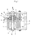
- the thread brake contains an electromagnet 1 with a winding 2 and a core 3, an armature 4, an active braking element 5, a passive braking element 6 and a stationary holder 7.
- the electromagnet 1 is fastened to the holder 7.
- a receiving part 8 is provided, in which the winding 2 and the core 3 are arranged.
- the winding 2 is designed as a ring coil and is attached to the receiving part on one end face.
- the core 3 is a stud with an external thread section 9 on one End and formed with a recess 10 for attaching a tool at the other end.
- the core 3 passes through the winding 2 and is screwed into the receiving part 8 such that a section 11 protrudes from the receiving part 8.
- the armature 4 is arranged in a second receiving part 12.
- the second receiving part 12 is displaceably arranged in the holder 7 in such a way that the pole face 13 of the core 3 and the pole face 14 of the armature 4 lie opposite one another.
- the braking members 5, 6 are plate-shaped, consist of metal and are arranged movably, specifically on a sleeve 15 made of insulating material, which is placed on the section 11 of the core 3 with play.
- the passive braking element 6 rests on the receiving part 8 for the electromagnet 1.
- the active braking member 5 rests on the second receiving part 12 when a thread 16 to be braked lies between the braking members 5, 6, an air gap a being present between the pole faces 13 and 14, respectively.
- the braking members 5, 6 are arranged so that they can rotate, so that the braking members 5, 6 can rotate during the braking operation, which is advantageous for certain types of thread.
- a permanent magnet 18 is assigned to each braking member 5, 6, so that a braking effect is achieved.
- the winding 2 is connected to a current source 19.
- the distance between the braking members 5, 6 can be set without or with a thread 16.
- the active braking member 5 is pressed manually in the direction of arrow A against the passive braking member 6, an insert (feeler gauge) is inserted between the pole faces 13, 14 and the core 3 is adjusted by turning until the pole face 13 of the core on the Insert is present.
- an insert When setting with thread, an insert can be used as described above.
- a particularly advantageous setting of the thread brake with thread is that the active braking element 5 is pressed manually against the thread 16 via the receiving part 12 or by means of a hold-down device (not shown), the core 3 is adjusted until the pole faces 13, 14 abut one another and continue to rotate until the thread is just freely movable again and ultimately adjusts the core 3 by rotating it by a certain angular dimension in the opposite direction, so that a defined air gap is present between the pole faces 13, 14.
- the setting can be carried out very easily and the thread 16 is applied in a particularly advantageous manner with constant braking force.
- the functioning of the thread brake is based solely on the armature 4 being attracted by the excited electromagnet 1.
- FIG. 2 shows another embodiment of the thread brake, in which the armature is repelled when the electromagnet is excited.
- the thread brake has the same basic structure.
- the thread brake contains the Electromagnet 1 with the winding 2 and the core 3, the armature 4, the active braking element 5, the passive braking element 6 and the stationary holder 7.
- the electromagnet 1, the armature 4 and the braking members 5, 6 are designed and arranged in the same way as in the embodiment according to FIG. 1, so that only those elements of the thread brake are described which are different from the embodiment according to FIG.
- the electromagnet 1 is fastened to a receiving part 22 which has a circular recess 23 into which the core 3 protrudes, so that its pole face 13 is exposed.
- the armature part 4 is arranged in a cup-like receiving part 24, specifically in the bottom part 25, so that the pole face 14 is exposed on the underside.
- the cup-shaped receiving part 24 is guided in the recess 23 and secured against rotation by a pin 26.
- the braking members 5, 6 are arranged on a pin 27 with a collar 28 and a threaded part 29 which is screwed into the holder 7.
- the sleeve 15 is plugged with play, on the outer surface of which the braking members 5, 6 are arranged movably.
- a cup-shaped support part 30 is provided, which is secured against rotation by means of a pin 31.
- the thread brake is set essentially the same as for the thread brake according to FIG. 1.
- FIG. 3 shows an arrangement with a thread brake with automatic braking force adjustment.
- the core 3 of the electromagnet is connected to an actuating element 35.
- the arrangement further comprises a thread tension sensor 36 and a control device 37, which is connected in a signal-transmitting manner to the winding 2 and to the control element 35.
- a sensor 36 is arranged in front of the thread brake in the thread running direction.
- a thread guide member 38 is also provided between the sensor 36 and the thread brake. The thread tension is sensed by means of the sensor 36 and a signal is applied to the control device 37. On the basis of a setpoint / actual value comparison, the winding 2 is supplied with higher or lower current, as a result of which the braking force is increased or decreased.
- the thread brake contains a stationary electromagnet 1 with a winding 2 and a core 3, an armature 4, and a passive and an active braking element 5, 6.
- the active braking element 5 is coupled to the armature 4 and is energized against the when the electromagnet is excited passive braking element 6 moves.
- the core 3 has a threaded portion to set an air gap a between the core 3 and the armature 4. By adjusting the pole face 13 of the core 3 with respect to the active braking member 5, the braking force can be set independently of the yarn thickness.
Landscapes
- Engineering & Computer Science (AREA)
- Textile Engineering (AREA)
- Tension Adjustment In Filamentary Materials (AREA)
- Electromagnets (AREA)
- Braking Arrangements (AREA)
- Looms (AREA)
Abstract
Description
Die vorliegende Erfindung betrifft eine elektromagnetische Fadenbremse gemäss dem Oberbegriff des Anspruches 1 und eine Webmaschine mit einer Fadenbremse.The present invention relates to an electromagnetic thread brake according to the preamble of
Aus der DE-U-73 46 075 ist eine Garnklemme bekannt, die eine ortsfeste und eine bewegliche Klemmbacke, einen Elektromagneten und einen Anker aufweist. Die bewegliche Klemmbacke ist mit dem Anker verbunden und wird bei Erregung des Elektromagneten gegen die ortsfeste Klemmbacke bewegt.From DE-U-73 46 075 a yarn clamp is known which has a fixed and a movable clamping jaw, an electromagnet and an armature. The movable jaw is connected to the armature and is moved against the stationary jaw when the electromagnet is excited.
Diese Vorrichtung hat die Nachteile, dass ein Faden lediglich geklemmt wird.This device has the disadvantages that a thread is only clamped.
Der Erfindung liegt die Aufgabe zugrunde, eine elektromagnetische Fadenbremse zu schaffen, bei der unabhängig von Abstand der Bremsorgane der gleiche Bremskraftwert erzeugt wird.The invention has for its object to provide an electromagnetic thread brake in which the same braking force value is generated regardless of the distance between the braking members.
Die mit der Erfindung erzielbaren Vorteile sind im Wesentlichen darin zu sehen, dass der Luftspalt zwischen dem Magnetkern und dem Anker einstellbar ist, womit gleichzeitig die Bremskraft unabhängig von der Garndicke einstellbar ist, die Fadenklemme über ein grossen Bereich der Garndicke anwendbar ist, die Einstellung auf die Garndicke sehr einfach durchführbar ist und die Bremskraft auf unterschiedliche Garnarten angepasst werden kann.The advantages achievable with the invention are essentially to be seen in the fact that the air gap between the magnetic core and the armature can be adjusted, which means that the braking force can be adjusted independently of the yarn thickness, the thread clamp over a large range the yarn thickness is applicable, the adjustment to the yarn thickness is very easy to carry out and the braking force can be adapted to different types of yarn.
Vorteilhafte Ausführungsformen der Erfindung ergeben sich aus den abhängigen Ansprüchen.Advantageous embodiments of the invention result from the dependent claims.
Eine Webmaschine mit einer Fadenbremse ist durch die Merkmale des Anspruches 9 gekennzeichnet.A loom with a thread brake is characterized by the features of
Nachfolgend wird die Erfindung anhand der beiliegenden Zeichnungen erläutert.The invention is explained below with reference to the accompanying drawings.
Es zeigen:
- Fig. 1
- eine bevorzugte Ausführungsform einer erfindungsgemässen Fadenbremse;
- Fig. 2
- eine andere Ausführungsform einer erfindungsgemässen Fadenbremse und
- Fig. 3
- eine weitere Ausführungsform einer erfindungsgemässen Bremse.
- Fig. 1
- a preferred embodiment of a thread brake according to the invention;
- Fig. 2
- another embodiment of a thread brake according to the invention and
- Fig. 3
- a further embodiment of a brake according to the invention.
Es wird auf Figur 1 Bezug genommen. Die Fadenbremse enthält einen Elektromagneten 1 mit einer Wicklung 2 und einen Kern 3, einen Anker 4, ein aktives Bremsorgan 5, ein passives Bremsorgan 6 und einen ortsfesten Halter 7. Der Elektromagnet 1 ist am Halter 7 befestigt. Hierfür ist ein Aufnahmeteil 8 vorgesehen, in welchem die Wicklung 2 und der Kern 3 angeordnet sind. Die Wicklung 2 ist als Ringspule ausgebildet und an einer Stirnseite an dem Aufnahmeteil befestigt. Der Kern 3 ist als Stiftschraube mit einem Aussengewindeabschnitt 9 an einem Ende und mit einer Ausnehmung 10 zum Ansetzen eines Werkzeuges am anderen Ende ausgebildet. Der Kern 3 durchgreift die Wicklung 2 und ist in den Aufnahmeteil 8 so eingeschraubt, dass ein Abschnitt 11 aus dem Aufnahmeteil 8 herausragt.Reference is made to FIG. 1. The thread brake contains an
Der Anker 4 ist in einem zweiten Aufnahmeteil 12 angeordnet. Der zweite Aufnahmeteil 12 ist im Halter 7 verschiebbar so angeordnet, dass die Polfläche 13 des Kernes 3 und die Polfläche 14 des Ankers 4 einander gegenüberliegen. Die Bremsorgane 5, 6 sind tellerförmig ausgebildet, bestehen aus Metall und sind beweglich angeordnet und zwar auf einer Hülse 15 aus Isoliermaterial, die mit Spiel auf dem Abschnitt 11 des Kernes 3 aufgesetzt ist. Das passive Bremsorgan 6 liegt am Aufnahmeteil 8 für den Elektromagneten 1 an. Das aktive Bremsorgan 5 liegt am zweiten Aufnahmeteil 12 an, wenn ein zu bremsender Faden 16 zwischen den Bremsorganen 5, 6 liegt, wobei zwischen den Polflächen 13 bzw. 14 ein Luftspalt a vorhanden ist.The armature 4 is arranged in a second receiving
Zwischen dem Halter 7 und dem Aufnahmeteil 12 ist ein einstellbarer Abstand b, um einerseits ein ungehindertes Durchlaufen eines Knotens zwischen den Bremsorganen 5, 6 zu ermöglichen, jedoch andererseits einen zu grossen Abstand verhindert.There is an adjustable distance b between the
Die Bremsorgane 5, 6 sind drehbeweglich angeordnet, so dass während des Bremsvorganges sich die Bremsorgane 5, 6 drehen können, was für bestimmte Fadenarten von Vorteil ist. Um eine unkontrollierte Drehung der Bremsorgane zu verhindern, ist jedem Bremsorgan 5, 6 ein Permanentmagnet 18 zugeordnet, so dass eine Bremswirkung erzielt wird. Die Wicklung 2 ist mit einer Stromquelle 19 verbunden.The
Die Einstellung des Abstandes zwischen Bremsorganen 5, 6 kann ohne oder mit einem Faden 16 erfolgen. Bei der Einstellung ohne Faden wird das aktive Bremsorgan 5 manuell in Richtung des Pfeiles A gegen das passive Bremsorgan 6 gedrückt, eine Einlage (Fühlerlehre) zwischen die Polflächen 13, 14 eingelegt und der Kern 3 durch Drehen verstellt bis die Polfläche 13 des Kernes an der Einlage anliegt.The distance between the
Bei der Einstellung mit Faden kann wie vorstehend beschrieben eine Einlage verwendet werden. Eine besonders vorteilhafte Einstellung der Fadenbremse mit Faden besteht darin, dass man das aktive Bremsorgan 5 via den Aufnahmeteil 12 manuell oder durch einen (nicht dargestellten) Niederhalter gegen den Faden 16 drückt, den Kern 3 verstellt bis die Polflächen 13, 14 aneinander liegen und weiterdreht, bis der Faden gerade wieder frei beweglich ist und letztlich den Kern 3 durch Verdrehen um ein bestimmtes Winkelmass in der Gegenrichtung verstellt, so dass ein definierter Luftspalt zwischen den Polflächen 13, 14 vorhanden ist.When setting with thread, an insert can be used as described above. A particularly advantageous setting of the thread brake with thread is that the
Aus dem vorstehenden ist ersichtlich, dass die Einstellung sehr einfach durchführbar ist und der Faden 16 in besonders vorteilhafter Weise mit gleichbleibender Bremskraft beaufschlagt wird. Die Funktionsweise der Fadenbremse beruht lediglich darauf, dass durch den erregten Elektromagnet 1 der Anker 4 angezogen wird.From the above it can be seen that the setting can be carried out very easily and the
Die Figur 2 zeigt eine andere Ausführungsform der Fadenbremse, bei welcher der Anker bei erregten Elektromagnet abgestossen wird.FIG. 2 shows another embodiment of the thread brake, in which the armature is repelled when the electromagnet is excited.
Wie die Figur 2 zeigt, weist die Fadenbremse den gleichen Grundaufbau auf. Die Fadenbremse enthält den Elektromagnet 1 mit der Wicklung 2 und dem Kern 3, den Anker 4, das aktive Bremsorgan 5, das passive Bremsorgan 6 und den ortsfesten Halter 7.As FIG. 2 shows, the thread brake has the same basic structure. The thread brake contains the
Der Elektromagnet 1, der Anker 4 und die Bremsorgane 5, 6 sind gleich wie bei der Ausführungsform gemäss Figur 1 ausgebildet und angeordnet, so dass lediglich jene Elemente der Fadenbremse beschrieben werden, welche gegenüber der Ausführungsform gemäss Figur 1 anders ausgebildet sind.The
Der Elektromagnet 1 ist an einem Aufnahmeteil 22 befestigt, der eine kreisförmige Ausnehmung 23 aufweist, in welche der Kern 3 hineinragt, so dass dessen Polfläche 13 freiliegt.The
Der Ankerteil 4 ist in einem becherartigen Aufnahmeteil 24 und zwar im Bodenteil 25 so angeordnet, dass die Polfläche 14 an der Unterseite freiliegt. Der becherförmige Aufnahmeteil 24 ist in der Ausnehmung 23 geführt und durch einen Stift 26 gegen Verdrehen gesichert.The armature part 4 is arranged in a cup-like receiving
Die Bremsorgane 5, 6 sind auf einem Zapfen 27 mit einem Bund 28 und einem Gewindeteil 29 angeordnet, der in den Halter 7 eingeschraubt ist. Auf dem Zapfen 27 ist die Hülse 15 mit Spiel aufgesteckt, an deren Mantelfläche die Bremsorgane 5, 6 beweglich angeordnet sind.The
Zwischen dem Halter 7 und den Bremsorganen 5, 6 ist ein becherförmiges Stützteil 30 vorgesehen, das mittels eines Stiftes 31 gegen Verdrehen gesichert ist.Between the
Die Einstellung der Fadenbremse erfolgt im Wesentlichen gleich wie bei der Fadenbremse gemäss Fig. 1.The thread brake is set essentially the same as for the thread brake according to FIG. 1.
Die Figur 3 zeigt eine Anordnung mit einer Fadenbremse mit automatischer Bremskrafteinstellung. Hierzu ist der Kern 3 des Elektromagneten mit einem Stellelement 35 verbunden.FIG. 3 shows an arrangement with a thread brake with automatic braking force adjustment. For this purpose, the
Die Anordnung umfasst ferner einen Fadenspannungssensor 36 und eine Steuereinrichtung 37, die signalübertragend mit der Wicklung 2 und mit dem Stellelement 35 verbunden ist. Ein Sensor 36 ist in Fadenlaufrichtung vor der Fadenbremse angeordnet. Zwischen dem Sensor 36 und der Fadenbremse ist ferner ein Fadenführungsorgan 38 vorgesehen. Mittels des Sensors 36 wird die Fadenspannung abgetastet und ein Signal an die Steuereinrichtung 37 angelegt. Aufgrund eines Soll-/Istwert-Vergleiches wird die Wicklung 2 mit höheren oder niedrigeren Strom versorgt, wodurch die Bremskraft erhöht oder verringert wird.The arrangement further comprises a
Die Fadenbremse enthält einen ortsfest angeordneten Elektromagneten 1 mit einer Wicklung 2 und einem Kern 3, einen Anker 4, und ein passives und ein aktives Bremsorgan 5, 6. Das aktive Bremsorgan 5 ist mit dem Anker 4 gekoppelt und wird bei Erregung des Elektromagneten gegen das passive Bremsorgan 6 bewegt. Der Kern 3 hat einen Gewindeabschnitt, um einen Luftspalt a zwischen dem Kern 3 und dem Anker 4 einzustellen. Durch die Verstellung der Polfläche 13 des Kernes 3 bezüglich des aktiven Bremsorgans 5 kann die Bremskraft unabhängig von der Garndicke eingestellt werden.The thread brake contains a
Claims (9)
Priority Applications (2)
| Application Number | Priority Date | Filing Date | Title |
|---|---|---|---|
| EP19950810479 EP0756028B1 (en) | 1995-07-24 | 1995-07-24 | Electromagnetic yarn brake and loom with such yarn brake |
| DE59507651T DE59507651D1 (en) | 1995-07-24 | 1995-07-24 | Electromagnetic thread brake and weaving machine with a thread brake |
Applications Claiming Priority (1)
| Application Number | Priority Date | Filing Date | Title |
|---|---|---|---|
| EP19950810479 EP0756028B1 (en) | 1995-07-24 | 1995-07-24 | Electromagnetic yarn brake and loom with such yarn brake |
Publications (2)
| Publication Number | Publication Date |
|---|---|
| EP0756028A1 true EP0756028A1 (en) | 1997-01-29 |
| EP0756028B1 EP0756028B1 (en) | 2000-01-19 |
Family
ID=8221774
Family Applications (1)
| Application Number | Title | Priority Date | Filing Date |
|---|---|---|---|
| EP19950810479 Expired - Lifetime EP0756028B1 (en) | 1995-07-24 | 1995-07-24 | Electromagnetic yarn brake and loom with such yarn brake |
Country Status (2)
| Country | Link |
|---|---|
| EP (1) | EP0756028B1 (en) |
| DE (1) | DE59507651D1 (en) |
Cited By (4)
| Publication number | Priority date | Publication date | Assignee | Title |
|---|---|---|---|---|
| WO1999028228A1 (en) * | 1997-12-03 | 1999-06-10 | Iro Patent Ag | Yarn tensioning device |
| WO2000037721A1 (en) * | 1998-12-18 | 2000-06-29 | Iro Patent Ag | Yarn processing system and method for delivering weft yarns |
| WO2002066354A2 (en) * | 2001-02-16 | 2002-08-29 | Iropa Ag | Thread gripper |
| BE1014435A5 (en) * | 2001-10-19 | 2003-10-07 | Dirk Benoit | Yarn tension control device with brake for e.g. weaving or knitting machines, alters braking force in response to deviation from desired tension value |
Families Citing this family (1)
| Publication number | Priority date | Publication date | Assignee | Title |
|---|---|---|---|---|
| CN105819275B (en) * | 2016-05-19 | 2018-10-26 | 青岛宏大纺织机械有限责任公司 | A kind of automatic winder tenslator |
Citations (5)
| Publication number | Priority date | Publication date | Assignee | Title |
|---|---|---|---|---|
| FR1197521A (en) * | 1958-07-04 | 1959-12-01 | Thread tensioner for machines and devices working with threads | |
| DE1070531B (en) * | 1959-12-03 | Deutsche Edelstahlwerke Aktiengesellschaft, Krefeld | Thread brake | |
| DE7346075U (en) | 1974-05-02 | Rueti Te Strake Bv | Twine clamp | |
| DE2452983A1 (en) * | 1974-09-06 | 1976-03-25 | Peyer Siegfried | DEVICE FOR THE GENERATION OF ADJUSTABLE TENSION OF A THREAD ON A TEXTILE MACHINE |
| GB2125072A (en) * | 1982-08-07 | 1984-02-29 | Geoffrey Edmund Whellams | Self-adjusting filament tensioner |
-
1995
- 1995-07-24 EP EP19950810479 patent/EP0756028B1/en not_active Expired - Lifetime
- 1995-07-24 DE DE59507651T patent/DE59507651D1/en not_active Expired - Fee Related
Patent Citations (5)
| Publication number | Priority date | Publication date | Assignee | Title |
|---|---|---|---|---|
| DE1070531B (en) * | 1959-12-03 | Deutsche Edelstahlwerke Aktiengesellschaft, Krefeld | Thread brake | |
| DE7346075U (en) | 1974-05-02 | Rueti Te Strake Bv | Twine clamp | |
| FR1197521A (en) * | 1958-07-04 | 1959-12-01 | Thread tensioner for machines and devices working with threads | |
| DE2452983A1 (en) * | 1974-09-06 | 1976-03-25 | Peyer Siegfried | DEVICE FOR THE GENERATION OF ADJUSTABLE TENSION OF A THREAD ON A TEXTILE MACHINE |
| GB2125072A (en) * | 1982-08-07 | 1984-02-29 | Geoffrey Edmund Whellams | Self-adjusting filament tensioner |
Cited By (7)
| Publication number | Priority date | Publication date | Assignee | Title |
|---|---|---|---|---|
| WO1999028228A1 (en) * | 1997-12-03 | 1999-06-10 | Iro Patent Ag | Yarn tensioning device |
| WO2000037721A1 (en) * | 1998-12-18 | 2000-06-29 | Iro Patent Ag | Yarn processing system and method for delivering weft yarns |
| US6418977B1 (en) | 1998-12-18 | 2002-07-16 | Iro Patent Ag | Yarn processing system with weft yarn tension regulation |
| CN1098943C (en) * | 1998-12-18 | 2003-01-15 | Iropa股份公司 | Yarn processing system and method for delivering weft yarns |
| WO2002066354A2 (en) * | 2001-02-16 | 2002-08-29 | Iropa Ag | Thread gripper |
| WO2002066354A3 (en) * | 2001-02-16 | 2003-12-11 | Iropa Ag | Thread gripper |
| BE1014435A5 (en) * | 2001-10-19 | 2003-10-07 | Dirk Benoit | Yarn tension control device with brake for e.g. weaving or knitting machines, alters braking force in response to deviation from desired tension value |
Also Published As
| Publication number | Publication date |
|---|---|
| EP0756028B1 (en) | 2000-01-19 |
| DE59507651D1 (en) | 2000-02-24 |
Similar Documents
| Publication | Publication Date | Title |
|---|---|---|
| EP0945534B1 (en) | Low inertia positiv yarn furnisher for elastomeric yarns | |
| DE4016720A1 (en) | METHOD AND DEVICE FOR ULTRASONIC BONDING | |
| DE3436187A1 (en) | TENSIONING DEVICE FOR A REEL WINDING MACHINE | |
| EP0613970A1 (en) | Weft yarn brake with controllable braking | |
| DE69000670T2 (en) | DEVICE FOR BRAKING A WIFE IN WEAVING MACHINES. | |
| DE60005244T3 (en) | Yarn brake for a weft supply device with reduced intervention times | |
| DD242386A5 (en) | THREADED BRAKE, PARTICULARLY FOR TEXTILE MACHINES | |
| DE9116562U1 (en) | Device for feeding threaded parts to a delivery point | |
| EP1480904B1 (en) | Device for detecting and/or adjusting a tensile force in a yarn | |
| EP0524429A1 (en) | Device for selective braking of threads or wires and the like | |
| EP0756028B1 (en) | Electromagnetic yarn brake and loom with such yarn brake | |
| DE2219127A1 (en) | Device for unwinding a rope under tension from a drum | |
| DE4029827C2 (en) | Spark erosive wire cutting machine with regulation of the wire tension | |
| EP0342358A1 (en) | Process and device for supplying a bonding wire | |
| EP0973686B1 (en) | Yarn tensioning device | |
| EP0344100B1 (en) | Electro-magnetical device for looms | |
| DE69319937T2 (en) | Device for the linear application of a thin metal wire on the surface of the thermoplastic film of a laminated glass pane | |
| EP0036066B1 (en) | Roving feed stop device for an open-end spinning device | |
| DE1952369B2 (en) | ARRANGEMENT FOR ADJUSTING VIDEO HEADS ON A HEADMARK | |
| DE19638238C1 (en) | Device for regulating the tensile force of a coil winding wire | |
| DE3239495C2 (en) | Ball brake for textile threads | |
| EP0326784B1 (en) | Braking method for a running thread, and thread brake to carry out the method | |
| EP0538307A1 (en) | Thread storage and feed device. | |
| DE19839272B4 (en) | Controllable thread brake | |
| EP0397187A1 (en) | Current supply device for an electro-erosion machine |
Legal Events
| Date | Code | Title | Description |
|---|---|---|---|
| PUAI | Public reference made under article 153(3) epc to a published international application that has entered the european phase |
Free format text: ORIGINAL CODE: 0009012 |
|
| AK | Designated contracting states |
Kind code of ref document: A1 Designated state(s): DE IT |
|
| AX | Request for extension of the european patent |
Free format text: SI |
|
| RBV | Designated contracting states (corrected) |
Designated state(s): DE IT |
|
| 17P | Request for examination filed |
Effective date: 19970602 |
|
| GRAG | Despatch of communication of intention to grant |
Free format text: ORIGINAL CODE: EPIDOS AGRA |
|
| 17Q | First examination report despatched |
Effective date: 19990226 |
|
| GRAG | Despatch of communication of intention to grant |
Free format text: ORIGINAL CODE: EPIDOS AGRA |
|
| GRAH | Despatch of communication of intention to grant a patent |
Free format text: ORIGINAL CODE: EPIDOS IGRA |
|
| GRAH | Despatch of communication of intention to grant a patent |
Free format text: ORIGINAL CODE: EPIDOS IGRA |
|
| GRAA | (expected) grant |
Free format text: ORIGINAL CODE: 0009210 |
|
| AK | Designated contracting states |
Kind code of ref document: B1 Designated state(s): DE IT |
|
| REF | Corresponds to: |
Ref document number: 59507651 Country of ref document: DE Date of ref document: 20000224 |
|
| ITF | It: translation for a ep patent filed | ||
| RAP2 | Party data changed (patent owner data changed or rights of a patent transferred) |
Owner name: SULZER TEXTIL AG |
|
| PLBE | No opposition filed within time limit |
Free format text: ORIGINAL CODE: 0009261 |
|
| STAA | Information on the status of an ep patent application or granted ep patent |
Free format text: STATUS: NO OPPOSITION FILED WITHIN TIME LIMIT |
|
| 26N | No opposition filed | ||
| PGFP | Annual fee paid to national office [announced via postgrant information from national office to epo] |
Ref country code: DE Payment date: 20040706 Year of fee payment: 10 |
|
| PG25 | Lapsed in a contracting state [announced via postgrant information from national office to epo] |
Ref country code: IT Free format text: LAPSE BECAUSE OF NON-PAYMENT OF DUE FEES;WARNING: LAPSES OF ITALIAN PATENTS WITH EFFECTIVE DATE BEFORE 2007 MAY HAVE OCCURRED AT ANY TIME BEFORE 2007. THE CORRECT EFFECTIVE DATE MAY BE DIFFERENT FROM THE ONE RECORDED. Effective date: 20050724 |
|
| PG25 | Lapsed in a contracting state [announced via postgrant information from national office to epo] |
Ref country code: DE Free format text: LAPSE BECAUSE OF NON-PAYMENT OF DUE FEES Effective date: 20060201 |