EP0754912A2 - Combustion process and apparatus therefor containing separate injection of fuel and oxidant streams - Google Patents
Combustion process and apparatus therefor containing separate injection of fuel and oxidant streams Download PDFInfo
- Publication number
- EP0754912A2 EP0754912A2 EP96401578A EP96401578A EP0754912A2 EP 0754912 A2 EP0754912 A2 EP 0754912A2 EP 96401578 A EP96401578 A EP 96401578A EP 96401578 A EP96401578 A EP 96401578A EP 0754912 A2 EP0754912 A2 EP 0754912A2
- Authority
- EP
- European Patent Office
- Prior art keywords
- fuel
- oxidant
- cavities
- fluid
- further characterized
- Prior art date
- Legal status (The legal status is an assumption and is not a legal conclusion. Google has not performed a legal analysis and makes no representation as to the accuracy of the status listed.)
- Granted
Links
- 239000000446 fuel Substances 0.000 title claims abstract description 440
- 239000007800 oxidant agent Substances 0.000 title claims abstract description 277
- 230000001590 oxidative effect Effects 0.000 title claims abstract description 276
- 238000002485 combustion reaction Methods 0.000 title claims abstract description 104
- 238000002347 injection Methods 0.000 title claims description 23
- 239000007924 injection Substances 0.000 title claims description 23
- 239000012530 fluid Substances 0.000 claims abstract description 174
- 239000007788 liquid Substances 0.000 claims description 79
- VNWKTOKETHGBQD-UHFFFAOYSA-N methane Chemical compound C VNWKTOKETHGBQD-UHFFFAOYSA-N 0.000 claims description 66
- 239000001301 oxygen Substances 0.000 claims description 58
- 229910052760 oxygen Inorganic materials 0.000 claims description 58
- QVGXLLKOCUKJST-UHFFFAOYSA-N atomic oxygen Chemical compound [O] QVGXLLKOCUKJST-UHFFFAOYSA-N 0.000 claims description 57
- 239000007789 gas Substances 0.000 claims description 38
- 238000000034 method Methods 0.000 claims description 37
- 239000003345 natural gas Substances 0.000 claims description 32
- 239000000463 material Substances 0.000 claims description 15
- 238000009826 distribution Methods 0.000 claims description 11
- MCMNRKCIXSYSNV-UHFFFAOYSA-N Zirconium dioxide Chemical compound O=[Zr]=O MCMNRKCIXSYSNV-UHFFFAOYSA-N 0.000 claims description 8
- 239000000203 mixture Substances 0.000 claims description 7
- ATUOYWHBWRKTHZ-UHFFFAOYSA-N Propane Chemical compound CCC ATUOYWHBWRKTHZ-UHFFFAOYSA-N 0.000 claims description 6
- 230000005484 gravity Effects 0.000 claims description 4
- 230000007480 spreading Effects 0.000 claims description 4
- 238000003892 spreading Methods 0.000 claims description 4
- PNEYBMLMFCGWSK-UHFFFAOYSA-N aluminium oxide Inorganic materials [O-2].[O-2].[O-2].[Al+3].[Al+3] PNEYBMLMFCGWSK-UHFFFAOYSA-N 0.000 claims description 3
- 230000002093 peripheral effect Effects 0.000 claims description 3
- 239000001294 propane Substances 0.000 claims description 3
- VYPSYNLAJGMNEJ-UHFFFAOYSA-N silicon dioxide Inorganic materials O=[Si]=O VYPSYNLAJGMNEJ-UHFFFAOYSA-N 0.000 claims description 3
- 239000000377 silicon dioxide Substances 0.000 claims description 3
- 239000003949 liquefied natural gas Substances 0.000 claims description 2
- UGFAIRIUMAVXCW-UHFFFAOYSA-N Carbon monoxide Chemical compound [O+]#[C-] UGFAIRIUMAVXCW-UHFFFAOYSA-N 0.000 claims 1
- 229910002091 carbon monoxide Inorganic materials 0.000 claims 1
- 239000001257 hydrogen Substances 0.000 claims 1
- 229910052739 hydrogen Inorganic materials 0.000 claims 1
- 125000004435 hydrogen atom Chemical class [H]* 0.000 claims 1
- 239000002737 fuel gas Substances 0.000 abstract description 29
- 238000000889 atomisation Methods 0.000 description 46
- MWUXSHHQAYIFBG-UHFFFAOYSA-N nitrogen oxide Inorganic materials O=[N] MWUXSHHQAYIFBG-UHFFFAOYSA-N 0.000 description 44
- 239000007921 spray Substances 0.000 description 19
- 239000011521 glass Substances 0.000 description 17
- 230000015572 biosynthetic process Effects 0.000 description 13
- IJGRMHOSHXDMSA-UHFFFAOYSA-N Atomic nitrogen Chemical compound N#N IJGRMHOSHXDMSA-UHFFFAOYSA-N 0.000 description 12
- 230000001965 increasing effect Effects 0.000 description 12
- 239000000295 fuel oil Substances 0.000 description 8
- 230000008569 process Effects 0.000 description 8
- 239000004071 soot Substances 0.000 description 8
- MYMOFIZGZYHOMD-UHFFFAOYSA-N Dioxygen Chemical compound O=O MYMOFIZGZYHOMD-UHFFFAOYSA-N 0.000 description 7
- 239000000919 ceramic Substances 0.000 description 7
- 239000000155 melt Substances 0.000 description 7
- 230000008859 change Effects 0.000 description 6
- 229910052757 nitrogen Inorganic materials 0.000 description 6
- 238000012360 testing method Methods 0.000 description 6
- 238000012546 transfer Methods 0.000 description 6
- 230000003247 decreasing effect Effects 0.000 description 5
- 238000013461 design Methods 0.000 description 5
- 239000000839 emulsion Substances 0.000 description 5
- 239000003546 flue gas Substances 0.000 description 5
- 239000002245 particle Substances 0.000 description 5
- 238000000429 assembly Methods 0.000 description 4
- 230000000712 assembly Effects 0.000 description 4
- 238000001816 cooling Methods 0.000 description 4
- 230000000694 effects Effects 0.000 description 4
- 230000006872 improvement Effects 0.000 description 4
- 238000004519 manufacturing process Methods 0.000 description 4
- 238000002844 melting Methods 0.000 description 4
- 230000008018 melting Effects 0.000 description 4
- 239000002184 metal Substances 0.000 description 4
- 238000002156 mixing Methods 0.000 description 4
- 230000005855 radiation Effects 0.000 description 4
- 238000000926 separation method Methods 0.000 description 4
- 238000010008 shearing Methods 0.000 description 4
- 238000001179 sorption measurement Methods 0.000 description 4
- 239000011449 brick Substances 0.000 description 3
- 239000000571 coke Substances 0.000 description 3
- 238000010438 heat treatment Methods 0.000 description 3
- 239000006060 molten glass Substances 0.000 description 3
- 239000011819 refractory material Substances 0.000 description 3
- 239000000523 sample Substances 0.000 description 3
- 238000005070 sampling Methods 0.000 description 3
- XLYOFNOQVPJJNP-UHFFFAOYSA-N water Substances O XLYOFNOQVPJJNP-UHFFFAOYSA-N 0.000 description 3
- CWYNVVGOOAEACU-UHFFFAOYSA-N Fe2+ Chemical compound [Fe+2] CWYNVVGOOAEACU-UHFFFAOYSA-N 0.000 description 2
- 229910001882 dioxygen Inorganic materials 0.000 description 2
- 238000007254 oxidation reaction Methods 0.000 description 2
- 238000007789 sealing Methods 0.000 description 2
- 230000006641 stabilisation Effects 0.000 description 2
- 238000011105 stabilization Methods 0.000 description 2
- 230000000087 stabilizing effect Effects 0.000 description 2
- 229910001220 stainless steel Inorganic materials 0.000 description 2
- OKTJSMMVPCPJKN-UHFFFAOYSA-N Carbon Chemical compound [C] OKTJSMMVPCPJKN-UHFFFAOYSA-N 0.000 description 1
- 238000003723 Smelting Methods 0.000 description 1
- 238000010521 absorption reaction Methods 0.000 description 1
- 230000009286 beneficial effect Effects 0.000 description 1
- 230000033228 biological regulation Effects 0.000 description 1
- 229910052799 carbon Inorganic materials 0.000 description 1
- 229910010293 ceramic material Inorganic materials 0.000 description 1
- 230000004087 circulation Effects 0.000 description 1
- 238000004140 cleaning Methods 0.000 description 1
- 238000000576 coating method Methods 0.000 description 1
- 238000009833 condensation Methods 0.000 description 1
- 230000005494 condensation Effects 0.000 description 1
- 230000003750 conditioning effect Effects 0.000 description 1
- 238000007796 conventional method Methods 0.000 description 1
- 230000007797 corrosion Effects 0.000 description 1
- 238000005260 corrosion Methods 0.000 description 1
- 230000003111 delayed effect Effects 0.000 description 1
- 230000001627 detrimental effect Effects 0.000 description 1
- 238000010790 dilution Methods 0.000 description 1
- 239000012895 dilution Substances 0.000 description 1
- KZHJGOXRZJKJNY-UHFFFAOYSA-N dioxosilane;oxo(oxoalumanyloxy)alumane Chemical compound O=[Si]=O.O=[Si]=O.O=[Al]O[Al]=O.O=[Al]O[Al]=O.O=[Al]O[Al]=O KZHJGOXRZJKJNY-UHFFFAOYSA-N 0.000 description 1
- 230000003670 easy-to-clean Effects 0.000 description 1
- 238000005485 electric heating Methods 0.000 description 1
- 230000002708 enhancing effect Effects 0.000 description 1
- 238000001704 evaporation Methods 0.000 description 1
- 230000008020 evaporation Effects 0.000 description 1
- 238000002474 experimental method Methods 0.000 description 1
- 238000001914 filtration Methods 0.000 description 1
- 230000004907 flux Effects 0.000 description 1
- 239000002803 fossil fuel Substances 0.000 description 1
- 239000000156 glass melt Substances 0.000 description 1
- 231100001261 hazardous Toxicity 0.000 description 1
- 239000013529 heat transfer fluid Substances 0.000 description 1
- 238000007689 inspection Methods 0.000 description 1
- 238000009688 liquid atomisation Methods 0.000 description 1
- 238000012423 maintenance Methods 0.000 description 1
- 239000012528 membrane Substances 0.000 description 1
- 238000012986 modification Methods 0.000 description 1
- 230000004048 modification Effects 0.000 description 1
- 239000012768 molten material Substances 0.000 description 1
- 229910052863 mullite Inorganic materials 0.000 description 1
- 239000003921 oil Substances 0.000 description 1
- 238000013021 overheating Methods 0.000 description 1
- 150000002926 oxygen Chemical class 0.000 description 1
- 238000003921 particle size analysis Methods 0.000 description 1
- 230000035515 penetration Effects 0.000 description 1
- 238000011020 pilot scale process Methods 0.000 description 1
- 239000002994 raw material Substances 0.000 description 1
- 230000009257 reactivity Effects 0.000 description 1
- 230000009467 reduction Effects 0.000 description 1
- 230000035939 shock Effects 0.000 description 1
- 238000004904 shortening Methods 0.000 description 1
- HBMJWWWQQXIZIP-UHFFFAOYSA-N silicon carbide Chemical compound [Si+]#[C-] HBMJWWWQQXIZIP-UHFFFAOYSA-N 0.000 description 1
- 229910010271 silicon carbide Inorganic materials 0.000 description 1
- 238000004088 simulation Methods 0.000 description 1
- 239000007787 solid Substances 0.000 description 1
- 239000010935 stainless steel Substances 0.000 description 1
- 238000006467 substitution reaction Methods 0.000 description 1
- 238000004227 thermal cracking Methods 0.000 description 1
- 238000011144 upstream manufacturing Methods 0.000 description 1
- 239000013598 vector Substances 0.000 description 1
- RUDFQVOCFDJEEF-UHFFFAOYSA-N yttrium(III) oxide Inorganic materials [O-2].[O-2].[O-2].[Y+3].[Y+3] RUDFQVOCFDJEEF-UHFFFAOYSA-N 0.000 description 1
Images





Classifications
-
- C—CHEMISTRY; METALLURGY
- C03—GLASS; MINERAL OR SLAG WOOL
- C03B—MANUFACTURE, SHAPING, OR SUPPLEMENTARY PROCESSES
- C03B5/00—Melting in furnaces; Furnaces so far as specially adapted for glass manufacture
- C03B5/16—Special features of the melting process; Auxiliary means specially adapted for glass-melting furnaces
- C03B5/235—Heating the glass
- C03B5/2353—Heating the glass by combustion with pure oxygen or oxygen-enriched air, e.g. using oxy-fuel burners or oxygen lances
-
- F—MECHANICAL ENGINEERING; LIGHTING; HEATING; WEAPONS; BLASTING
- F23—COMBUSTION APPARATUS; COMBUSTION PROCESSES
- F23D—BURNERS
- F23D14/00—Burners for combustion of a gas, e.g. of a gas stored under pressure as a liquid
- F23D14/20—Non-premix gas burners, i.e. in which gaseous fuel is mixed with combustion air on arrival at the combustion zone
- F23D14/22—Non-premix gas burners, i.e. in which gaseous fuel is mixed with combustion air on arrival at the combustion zone with separate air and gas feed ducts, e.g. with ducts running parallel or crossing each other
-
- F—MECHANICAL ENGINEERING; LIGHTING; HEATING; WEAPONS; BLASTING
- F23—COMBUSTION APPARATUS; COMBUSTION PROCESSES
- F23D—BURNERS
- F23D14/00—Burners for combustion of a gas, e.g. of a gas stored under pressure as a liquid
- F23D14/32—Burners for combustion of a gas, e.g. of a gas stored under pressure as a liquid using a mixture of gaseous fuel and pure oxygen or oxygen-enriched air
-
- F—MECHANICAL ENGINEERING; LIGHTING; HEATING; WEAPONS; BLASTING
- F23—COMBUSTION APPARATUS; COMBUSTION PROCESSES
- F23M—CASINGS, LININGS, WALLS OR DOORS SPECIALLY ADAPTED FOR COMBUSTION CHAMBERS, e.g. FIREBRIDGES; DEVICES FOR DEFLECTING AIR, FLAMES OR COMBUSTION PRODUCTS IN COMBUSTION CHAMBERS; SAFETY ARRANGEMENTS SPECIALLY ADAPTED FOR COMBUSTION APPARATUS; DETAILS OF COMBUSTION CHAMBERS, NOT OTHERWISE PROVIDED FOR
- F23M5/00—Casings; Linings; Walls
- F23M5/02—Casings; Linings; Walls characterised by the shape of the bricks or blocks used
- F23M5/025—Casings; Linings; Walls characterised by the shape of the bricks or blocks used specially adapted for burner openings
-
- F—MECHANICAL ENGINEERING; LIGHTING; HEATING; WEAPONS; BLASTING
- F23—COMBUSTION APPARATUS; COMBUSTION PROCESSES
- F23D—BURNERS
- F23D2900/00—Special features of, or arrangements for burners using fluid fuels or solid fuels suspended in a carrier gas
- F23D2900/00012—Liquid or gas fuel burners with flames spread over a flat surface, either premix or non-premix type, e.g. "Flächenbrenner"
- F23D2900/00013—Liquid or gas fuel burners with flames spread over a flat surface, either premix or non-premix type, e.g. "Flächenbrenner" with means for spreading the flame in a fan or fishtail shape over a melting bath
-
- Y—GENERAL TAGGING OF NEW TECHNOLOGICAL DEVELOPMENTS; GENERAL TAGGING OF CROSS-SECTIONAL TECHNOLOGIES SPANNING OVER SEVERAL SECTIONS OF THE IPC; TECHNICAL SUBJECTS COVERED BY FORMER USPC CROSS-REFERENCE ART COLLECTIONS [XRACs] AND DIGESTS
- Y02—TECHNOLOGIES OR APPLICATIONS FOR MITIGATION OR ADAPTATION AGAINST CLIMATE CHANGE
- Y02P—CLIMATE CHANGE MITIGATION TECHNOLOGIES IN THE PRODUCTION OR PROCESSING OF GOODS
- Y02P40/00—Technologies relating to the processing of minerals
- Y02P40/50—Glass production, e.g. reusing waste heat during processing or shaping
Definitions
- the present invention relates to a combustion process and an apparatus therefor containing separate injectors to introduce separately a fuel and an oxidant in the combustion chamber of a furnace, so that the fuel burns with the oxidant in a wide luminous flame, and whereby the combustion of the fuel with the oxidant generates reduced quantities of nitrogen oxides (NO x ).
- Industrial high temperature processes such as glass or frit melting, ferrous and non ferrous materials smelting, use large amounts of energy to transform a variety of raw materials into a hot molten product, that is then casted, formed or otherwise disposed of in further stages of the industrial process.
- This operation is generally performed in large furnaces, that can produce as much as 500 tons (metric) per day of molten material.
- Combustion in the furnace of a fossil fuel such as natural gas, atomized fuel oil, propane, or the like, with an oxidant that contains oxygen is a preferred method of supplying the energy. In some cases, the combustion is supplemented by electric heating.
- the fuel and the oxidant are introduced in the furnace through burners, in order to generate flames.
- the transfer of energy from the flames to the material to be melted results from the combination of convection at the surface of the material, and radiation to the surface or into the material if it is transparent to the radiation.
- Flames that are highly radiative are usually preferred, because they provide better heat transfer and, thus, higher fuel efficiency.
- the fuel usually contains some nitrogen, and oxygen supplied from non-cryogenic sources, such as oxygen produced by a Vacuum Swing Adsorption plant (VSA), contains a small residual nitrogen concentration.
- VSA Vacuum Swing Adsorption plant
- Conventional methods of combusting fuel and oxygen for heating furnaces utilize post mix oxy-fuel burners.
- Conventional oxy-fuel burners have a metallic body with inlets for a fuel and an oxidant with a high concentration of molecular oxygen, and means to transport the streams with separate coaxially oriented channels to multiple injectors located at the burner tip. These burners generate high temperature flames with the shape of a narrow pencil at the burner tip, which needs to be located far enough into the furnace, to avoid or reduce overheating of the furnace walls.
- a circulating fluid such as water provides the cooling.
- Such a burner is described, for example, in British Patent 1,215,925. Severe corrosion problems for the cooling jacket can arise particularly when the furnace atmosphere contains condensable vapors.
- the gas cooled oxy-fuel burner is an improvement of the water-cooled burner.
- the body of the burner is protected from the furnace radiation by a refractory brick often referred to as a burner block, that possesses a substantially cylindrical cavity that opens into the furnace.
- the burner is usually mounted at the back of the cavity, and it usually contains concentric injectors of fuel and oxidant located in the cavity, recessed from the furnace inner wall.
- the brick and the burner are cooled by a peripheral annular flow of gas, usually the oxidant gas.
- Such burners are described e.g. in USP 5,346,390 and USP 5,267,850. With this type of burner, combustion starts in the burner block before reaching the furnace.
- the flame is confined in and directed by the cylindrical cavity as a narrow axisymmetric jet, and provides insufficient covering of the melt in the furnace.
- These flames have high peak temperatures and generate relatively large amounts of NO x , because there is a direct contact between the oxygen and the fuel without dilution by the combustion products.
- Burners in use today typically are only designed to use gaseous fuel or liquid fuels (perhaps by spray of the liquid fuel), but cannot burn both types of fuel simultaneously, or switch easily from gaseous fuel to liquid fuel.
- Liquid fuels present their own problems to the combustion artisan.
- the liquid fuel is typically atomized, and there are several different techniques available for the atomization of liquid fluids.
- the object is to produce jets of liquid fluid droplets (also called “spray") which have defined geometric characteristics.
- the usual liquid fuels are not particularly flammable in the liquid state: only in the gaseous state are they able to support an oxidation reaction sufficiently rapid to give rise to the appearance of a flame.
- the principal difficulty is thus to "shrewdly condition" this liquid in such a way that it evaporates rapidly in order to support oxidation reactions in the interior of the flame.
- the method currently used to achieve this "shrewd conditioning" consists of atomizing the fuel in the form of droplets: thus, for a given quantity of fuel, this makes possible a substantial increase in the amount of liquid surface exposed to the oxidant (the smaller the drops are, the greater will be the interfacial surface -- the site of evaporation).
- Internal atomization is characterized by confinement of the liquid fuel and atomizing fluid in an emulsion chamber.
- the mode of introduction of the two fluids into this chamber can vary considerably and has a direct influence on the characteristics of the emulsion that exits from the chamber.
- the internal geometry of this chamber also affects the specific characteristics of the fuel/atomizing fluid mixture to be burned.
- This mode of atomization generally affords an excellent quality of atomization, that is, an emulsion composed of very small particles with a very narrow particle size distribution about these small diameters.
- this emulsion quality is naturally a function of the atomizing fluid delivery rate employed and the pressure level prevailing in the interior of the atomizing chamber.
- the emulsion is created mainly by shearing of the jet of liquid fuel by the atomizing fluid.
- the geometry of the outlets for the two fluids completely determines the quality of the atomization, and particle size analysis of the drops resulting from the contact shows a relatively wide diameter distribution (simultaneous presence of small and large particles).
- Another disclosed liquid fuel atomization device is the one disclosed in European Patent Application No. 0335728 A3, which claims a device for the introduction of a fluid into a combustion enclosure through the expedient of several distinct conduits branching from a common main conduit.
- a burner having the capability of burning gaseous fuels and liquid fuels, either at the same time or in the alternative.
- a fuel with oxygen contained in an oxidant gas are presented, wherein the fuel and oxidant gas are injected in separate fluid streams into a combustion chamber of a high temperature furnace (having a temperature of at least, 820°C or 1500°F) in such proportions that the molar ratio of oxygen in the oxidant flow to fuel flow is between 0.95 and 1.05 (stoichiometric ratio), the fuel and oxidant producing a wide, luminous, well-defined flame.
- Methods and systems of the present invention generate reduced quantities of NO x .
- the inventive burner assembly is characterized by at least one fuel fluid inlet and at least one oxidant fluid inlet, means for transporting the fuel fluid from the fuel inlet to a plurality of fuel outlets, the fuel fluid leaving the fuel outlets in fuel streams that are injected into a combustion chamber, means for transporting the oxidant fluid from the oxidant inlets to at least one oxidant outlet, the oxidant fluid leaving the oxidant outlets in oxidant fluid streams that are injected into the combustion chamber, with the fuel and oxidant outlets being physically separated, and geometrically arranged in order to impart to the fuel fluid streams and the oxidant fluid streams angles (referred to herein as "final" angles) and velocities (as the fuel and oxidant enter the combustion chamber) that allow combustion of the fuel fluid with the oxidant in a stable, wide, and luminous flame.
- one aspect of the invention is a burner assembly having improved flame length and shape control, characterized by: a refractory block adapted to be in fluid connection with sources of oxidant and fuel, the refractory block having a fuel and oxidant entrance end and a fuel and oxidant exit end, the exit end having fuel exits and oxidant exits, the refractory block further having a plurality of fuel cavities, at least two of the fuel cavities defining a first fuel plane, and a plurality of oxidant cavities defining a second oxidant plane, the fuel cavities being more numerous than the oxidant cavities.
- Preferred refractory blocks have at least five cavities, three cavities at a lower portion thereof for injection of fuel into a furnace combustion chamber, and two cavities at an upper portion thereof for injection of an oxidant into a furnace combustion chamber.
- the oxidant cavities are preferably more numerous than the fuel cavities.
- the refractory block has at least one liquid fuel cavity and at least one gaseous fuel cavity.
- the liquid fuel cavity be positioned below that gaseous fuel cavities, and the gaseous fuel cavities positioned below the oxidant cavities, as further described herein.
- the fuel and oxidant exits are circular and contoured.
- the cavities are preferably straight holes through the refractory block form a fluid entrance end of the block to a fluid exit end of the block.
- the burner assembly of the invention may in some preferred embodiments comprise a fuel distributor or atomizer which is a single, integral component which fits inside a cavity of the refractory block, the fuel distributor having multiple fuel exits.
- Another burner assembly embodiment of the invention is that characterized by a refractory block having a fuel and oxidant entrance end and a fuel and oxidant exit end, and further having a single liquid fuel cavity and a plurality of oxidant cavities, the oxidant cavities defining an oxidant plane which is positioned at an upper portion of the refractory block and above the liquid fuel cavity.
- Yet another burner assembly of the invention is characterized by a refractory block having a fuel and oxidant entrance end and a fuel and oxidant exit end, and further having a plurality of fuel cavities and a plurality of oxidant cavities, at least two of the oxidant cavities defining a first oxidant plane which is positioned at an upper portion of the refractory block and above a portion of the fuel cavities defining a fuel plane, wherein at least some of the oxidant cavities form a second plane at a position lower in the refractory block than the first oxidant plane, and wherein at least one of the oxidant cavities in the second oxidant plane has positioned therein a fuel injector having a diameter smaller than its corresponding oxidant cavity.
- Another burner assembly embodiment of the invention is characterized by a refractory block having a fuel and oxidant entrance end and a fuel and oxidant exit end, and further having a plurality of fuel cavities and a single oxidant cavity, said oxidant cavity positioned at an upper portion of the refractory block and above a portion of the fuel cavities defining a fuel plane.
- the oxidant cavity itself (cross-section) and its exit may be non-circular, such as rectangular, oval, ellipsoidal, and the like, in all cases preferably with contoured edges at the block exit face as described herein.
- Another aspect of the invention is a method of combustion of a fuel with an oxidant, the method is characterized by:
- two adjacent fuel fluid streams have a final diverging angle which is not greater than 15°.
- Other preferred methods are those wherein gaseous and liquid fuels are burned simultaneously, and methods wherein gaseous fuel (or liquid fuel) is burned first, followed by liquid fuel (or gaseous fuel).
- the flame breadth can be increased (without significant decrease in the flame length) by providing the fuel and/or oxidant flow cavities with a final divergence angle slightly more than their initial divergence angle, as further described herein.
- oxidant and fuel injectors are used (especially for fuel) which fit inside the fuel and/or oxidant cavities.
- oxidant cavities and fuel cavities include the provision of different distances between oxidant cavities and fuel cavities, depending on the type of fuel being burned (for example gaseous fuel vs. liquid fuel); non-parallel oxidant cavities (i.e. having diverging angles); and the provision, especially for fuel oil purposes, of a fuel injector having multiple diverging fuel sub-injectors, the fuel injector being located in one cavity of the refractory block.
- the combustion process and apparatus therefor are provided which operates with low oxidant supply pressure, such as the pressure delivered by a vacuum swing adsorption oxygen production unit.
- Low oxidant pressure means a pressure ranging from 105,000 to 170,000 Pa (absolute pressure) (50 m bar to 0.7 bar/relative pressure).
- the fuel and the oxidant are introduced in the furnace through separate cavities in the burner assembly.
- fuel means, for example, methane, natural gas, liquefied natural gas, propane, atomized oil or the like (either in gaseous or liquid form) at either room temperature (25°C) or in preheated form.
- oxidant means a gas with an oxygen molar concentration of at least 50%.
- Such oxidants include oxygen-enriched air containing at least 50% vol., oxygen such as "industrially” pure oxygen (99.5%) produced by a cryogenic air separation plant or non-pure oxygen produced by e.g. a vacuum swing adsorption process (88% vol. O 2 or more) or "impure” oxygen produced from air or any other source by filtration, adsorption, absorption, membrane separation, or the like, at either room temperature or in preheated form.
- the cavities are passages through a ceramic block or through a furnace wall, and preferably have a generally cylindrical cross section. Any equivalent cross section can be used, such as square, rectangular, ellipsoid, oval, and the like.
- Injectors are defined herein as tubular members having an outer shape which mates with its respective cavity, and which can be placed in its respective cavity to prolong the use of the refractory burner block. Injectors can be either metallic tubes, metallic tubes or pipes with ceramic ends, ceramic tubes, or a combination thereof. Examples of suitable ceramic materials for injector tubes include alumina, zirconia, yttria, silicon carbide, and the like. Various stainless steels may be used for the injectors if the injectors are metallic, and metallic injectors having heat-protective refractory coatings, employing materials such as those mentioned for ceramic injectors, are also possible.
- injectors are preferred but not absolutely necessary.
- injectors would not be necessary if the cavities are covered or coated with a layer of ceramic or any other material which withstands the high temperature and has adequate non-porosity to avoid penetration of gas through the refractory block
- the injectors are installed in cavities opened through the furnace walls, or through a refractory or ceramic brick mounted in the furnace wall.
- the length of the injector is purposely made insufficient to span the respective length of its cavity in the burner block: the fuel or oxidant flows from the injector into the cavity, then from the cavity into the combustion chamber of the furnace.
- the injector stops before any change in direction of the gas flow that can be imparted by the geometry of the cavity; in other embodiments, the injector may protrude out of the refractory block and into the combustion chamber. In other embodiments there may be no injectors at all.
- the fuel injection is preferably made by at least two, preferably identical, cavities which axis are located preferably in a same plane, further referred to as the first fuel plane.
- the fuel and oxidant outlets are physically separated and geometrically arranged in order to impart to the fuel fluid streams and the oxidant fluid streams angles and velocities that allow combustion of the fuel fluid with the oxidant in a stable, wide, and luminous flame.
- the fuel cavities diverge at an initial angle, and then this initial divergence angle increases slightly just before the fuel enters the combustion chamber to the final divergence angle.
- This final divergence angle is preferably only a few degrees larger than the first divergence angle.
- a preferred final angle between two adjacent fuel cavities is between 3 and 10 degrees.
- the distance 1 between the extremities of the cavities when the fuel enters the combustion chamber of the furnace is comprised preferably between 4 and 10 times the inner diameter d of each fuel injector in the first plane.
- the first plane is preferably but not necessarily parallel to the melt surface.
- the dimension "d" is an equivalent diameter corresponding to the cross-sectional area of an equalivalent circular injector or cavity.
- fuel jets from the fuel cavities is such that it creates a fuel “sheet”.
- sheet it is meant a substantially continuous cloud of fuel droplets (if liquid) or fuel gas in an angle of the first plane of at most 120°, preferably between 20° and 60°, and preferably symmetrical relative to the longitudinal axis of symmetry of the fuel cavities.
- the velocity of the fuel gas in the cavities is preferably at least 15 m/s.
- a process wherein a "sheet" of fuel fluid is generated above the surface to be heated, e.g. by means of at least two fuel cavities that make a final diverging angle preferably smaller than 15 degrees, said fuel cavities being located in a first plane, an oxidant fluid having a lower velocity than that of the fuel fluid (preferably not exceeding 60 meters per second (m/s) being injected above the surface to be heated, preferably with at least two oxygen cavities, two adjacent oxygen cavities making a final diverging angle smaller than 15 degrees.
- These cavities are preferably located in a second plane, which converges to and intersects with the first plane in the combustion chamber.
- the low velocity oxidant fluid jets which intersect with the fuel sheet are dragged by the fuel flow along the fuel sheet, and create a combustion zone that stretches along the "sheet". Accordingly, at the beginning of the combustion zone of the combustion chamber, a fuel-rich region is maintained at the underside of the fuel cloud where significant amounts of soot are formed. The soot and the fuel are then progressively oxidized by the oxidant that diffuses along the combustion zone.
- a method of combustion in a combustion zone for a burner assembly containing at least two fuel fluid cavities, at least one oxidant fluid cavity and at least one exit face at which the fuel fluid cavities and oxidant fluid cavity terminates, the process entailing:
- the invention also provides stabilization of the flame with an auxiliary injection of fuel and/or oxidant gases.
- additional fuel cavities e.g. located in a second fuel plane, beneath the first fuel plane and preferably parallel to or slightly converging with the first fuel plane.
- the injection of the oxidant fluid is made by at least two, preferably identical, cavities whose axis are located in the same plane, namely a first oxidant plane.
- the axial distance L between the tips of the oxidant cavities where the oxidant flow enters the combustion chamber of the furnace is comprised preferably between 2 and 10 times the inner diameter D (or equivalent diameter, as defined previously for "d") of each oxidant injector in the second plane.
- Two adjacent oxidant cavities make a final diverging angle (in the direction of the flow) between 0 and 15 degrees, preferably between 0 and 7 degrees.
- the oxidant velocity in the cavities is smaller than the fuel velocity in the cavities of the first oxidant plane, and preferably smaller than 60 (m/s).
- the oxidant cavities contain so-called swirlers, intended to give to the oxidant streams a swirling motion to increase the spreading of the oxidant streams in the combustion zone, and improve the mixing between the oxidant and the fuel sheet.
- Suitable swirlers are metallic fins or twisted stripes of metal placed in the cavities or injectors.
- the total quantities of fuel and oxidant used by the combustion system are such that the flow of oxygen ranges from 0.95 to 1.05 of the theoretical stoichiometric flow of oxygen necessary to obtain the complete combustion of the fuel flow. Another expression of this statement is that the combustion ratio is between 0.95 and 1.05.
- the angle I between the first fuel plane and the second (oxidant) plane is between 0 and 20 degrees, the first fuel plane and second plane converging toward the combustion chamber.
- the distance h between the first fuel plane and the second plane is at least equal to 2 times the diameter D, in the vertical plane at the exit of the cavities, with the first fuel plane being considered as substantially horizontal.
- the present invention also relates to a burner assembly comprising at least two fuel fluid cavities, at least one oxidant fluid cavity and at least one exit face at which the fuel fluid cavities and the oxidant fluid cavity terminates, characterized by:
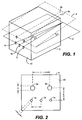
- a first refractory block component 5 of a burner assembly embodiment of the invention is illustrated in FIG. 1, having three fuel fluid cavities la, 1b, and 1c in a first plane 2, and two oxidant fluid cavities 3a and 3b in the second plane 4.
- the two first and second planes (2 and 4) make an angle I .
- the three fuel fluid cavities la, 1b, and lc make an angle ⁇ between two adjacent ones, preferably the same.
- the axis of the middle fuel cavity 1b is perpendicular to an exit face 10 of refractory block 5.
- FIG. 2 illustrates a front view of block 5 of FIG. 1.
- d represents the diameter of fuel cavities 1a, 1b, and lc at exit face 10; 1 represents their respective axial separation distance at exit face 10; D represents the diameter of oxidant cavities 3a and 3b at exit face 10; and L their respective axial separation distance at exit face 10.
- "h" represents the distance between planes 2 and 4 at exit face 10 of block 5. It is to be recognized that all dimensions described herein with reference to FIG. 2 may be modified based on the particular fuel used. For example, if fuel oil is used, the distance h would tend to be greater than if natural gas were used as the fuel.
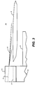
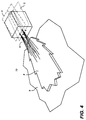
- FIG. 3 represents a schematic side elevation view of the operation of the combustion system of FIGs. 1 and 2 as used in, for example, a glass melting tank 12, while FIG. 4 illustrates a perspective view of the system of FIGs. 1-3.
- a fuel "sheet” or “cloud” is formed by fuel fluid streams exiting the fuel cavities in the first plane 2. Jets of oxidant 6 exit the cavities of the second plane 4, and intersect the fuel sheet in the combustion chamber 70 of the furnace. Combustion of the fuel with the oxidant occurs at an interface between the two flows to generate a flame 8 above the melt 9.
- the region located under the flame is fuel rich, which promotes the formation of carbon particles (soot) and thus enhances the luminosity of the flame.
- FIGs. 1 to 3 The configuration illustrated in FIGs. 1 to 3 was tested in a pilot scale furnace of square cross section (1 m wide and 2.5 meters long).
- the furnace was heated up to 820°C (1500°F) by an assist oxygen natural gas burner.
- the combustion system of the invention was started and the assist burner shut down.
- the flame was viewed from the side of the furnace which had viewing ports.
- the burner assembly including the refractory block illustrated in FIG. 1 was rotated (e.g. by 90 degrees), so that the flame could be better monitored from the side viewports.
- the first plane of the natural gas cavities was parallel to one of the furnace walls (side or bottom).
- the combustion system that was tested used natural gas flowing at 32 nm 3 /hr (1200 scfh) as a fuel fluid and pure oxygen flowing at 64 nm 3 /hr (2400 scfh) as the oxidant fluid under a pressure of 100 m bar above the furnace pressure. This represents a combustion ratio of 1.
- the distance L between the oxygen cavities was 15 cm.
- the angle between the natural gas cavities was 5 degrees.
- the arrangement allowed to vary the distance h between the first plane and the second plane from 2.5 cm to 10 cm, and the relative angle of the two oxygen cavities from 0 to 5 degrees.
- the cavities included injectors made of ceramic mullite tubes (stainless steel tubes have been further tested too).
- All cavities were mounted in cavities drilled through refractory material (referred to as the refractory block 5).
- the diameter of the natural gas cavities was varied between 0.925 cm and 1.58 cm (0.364 inches and 0.622 inches) so that fuel fluid velocities of 44 m/s, 26 m/s, and 16 m/s, were respectively achieved.
- the diameter of the oxygen cavities was varied between 1.9 and 2.66 cm (0.75 and 1.049 inches) so that oxygen velocities of 16 m/s, 27 m/s, and 31 m/s were achieved.
- the CO, O 2 , CO 2 , NO x contents in the flue gases were continuously monitored.
- the average furnace temperature was 1450°C for all the tests.
- a sampling probe was also introduced in the furnace, at a distance of two meters from the block 5 to measure the local CO concentration in the flame. Low measured CO concentrations at the sampling probe indicate short flames. Another indication of short flames for this particular furnace is the observation of relatively low temperature flue gases, with the same stoichiometric conditions.
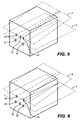
- the flame stability could be significantly improved without affecting the flame luminosity and the flame length if one natural gas injector is located in between the two oxygen cavities of the second plane, such as indicated on FIG. 5, preferably if one of the natural gas injector 21 in the first plane 2 is moved to the second plane 4, or close to it, substantially at the same distance from each oxygen injector 23, 24.
- the other two fuel cavities 20, 22 keep the same position.
- a combustion system according to the invention can thus be used to increase the heat transfer toward the load and reduce the furnace crown temperature.
- an equivalent improvement of the flame stability can be obtained if an auxiliary oxygen injector 25 is installed in the first plane 2 of the fuel cavities 20, 22, as shown for example on FIG. 6. (The same relative locations of this oxygen injector and the gas cavities applies, as disclosed on FIG. 5.) In this configuration, there are two oxygen cavities 23, 24 in the second plane 4 and two fuel cavities 20, 22 and one oxygen injector 25 in the first fuel plane 2.
- the flame length can be varied by changing the angle I between the second plane 4 of the oxygen cavities and the first fuel plane 2 of the fuel cavities.
- the flame stability is enhanced and maintained over the range of flame length adjustment by an auxiliary injection of fuel near the oxygen cavities, or an auxiliary injection of oxygen near the fuel cavities.
- Changing the angle between the two flames can also be used to increase the heat transfer towards the load of the furnace, and thus improve the efficiency of the fuel burnt.
- additional heat transfer in some areas of furnaces can be useful to enhance the convective circulations of the molten glass and/or increase the residence time of the molten glass in the furnace, which improves the glass quality.
- Combustion systems of the present invention are intended to be used, for example, to replace air-fuel combustion systems in already existing furnaces, and/or to be used as the main source of energy in new furnaces.
- a burner having oxidant exits which are slightly angled to the sides, and generally contoured, preferably rounded, at their tips (i.e. at the exit face 10). Quite surprisingly, it has been discovered that the angled exits allow the oxygen flow and, thus, the flame to be wider and prevent fuel from exiting unburned. Additionally, the rounded tips cause less turbulence, and, hence, afford a greater control over flame shape.
- a preferred burner assembly depicted in Figure 7 The principal components of a preferred burner assembly depicted in Figure 7 are: 1) a refractory block 5; 2) a mounting bracket assembly 72; 3) a fuel distributor 74, located at the bottom of the mounting bracket assembly, and 4) an oxidant distributor 76, located at the top of the mounting bracket assembly. Fuel is supplied through an inlet 78. Oxidant is supplied to the burner assembly through an inlet 80.
- FIGs. 8a plan view
- 8b end elevation
- 8c side elevation
- the fuel and oxidant cavities are straight holes through refractory block 5.
- the gas exit of each oxidant cavity and each fuel cavity have rounded edges at the gas exit face 10 as opposed to straight edges.
- the rounded edges reduce the velocity gradient between the gas flows ejected from the block and the surrounding atmosphere, which prevents particulates or volatile species contained in the atmosphere to build-up around the outlets of the cavities which in turn would alter the geometry of the cavities. This is particularly important in the case of the natural gas cavities, because the build-up process can be aggravated by the thermal cracking of the natural gas and the formation of coke deposits at the natural gas exits from the refractory blocks, which can alter flow direction in the furnace.
- the bottom cavities used for the fuel make a diverging angle ⁇ in order to distribute the fuel gas flow in a sheet pattern.
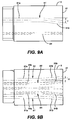
- the refractory block 5 illustrated in FIGs. 9a ( side elevation) and 9b (plan view) has five cavities: three cavities at the bottom for the injection of fuel in the furnace, and two cavities at the top for the oxidant injection.
- the refractory block 5 depicted in FIGs. 9a and 9b is preferably a single piece of refractory material having multiple cavities or through holes therethrough, such as cavities 91 and 92 for oxidant, and cavities 94, 96, and 98 for fuel. In the embodiment illustrated in FIGs.
- oxidant cavities 91 and 92 are initially parallel to each other and with the fuel cavities (see portions 91a and 92a), but then angle away from each other at an angle of 2 ⁇ , and toward the fuel cavities at an angle ⁇ .
- fuel cavities 94 and 98 (the two on either side of the block 5) angle away from the central fuel cavity 96 at an angle, preferably also ⁇ . This design allows the ability to position the exits of the fuel cavities closer to one another than in the embodiment illustrated in FIG. 8. Closer fuel exits might be useful when the fuel is fuel oil.
- Suitable materials for the refractory block are fused zirconia (ZrO 2 ), fused cast AZS (alumina-zirconia-silica), rebonded AZS, or fused cast alumina (Al 2 O 3 ).
- ZrO 2 fused zirconia
- fused cast AZS alumina-zirconia-silica
- rebonded AZS rebonded AZS
- fused cast alumina Al 2 O 3
- FIG. 8 Straight cavities as illustrated in FIG. 8 are easy to clean in case some material happens to block the gas outlets. However, angling out the last few centimeters of the cavities is enough to impart a diverging angle to the fuel gas streams.
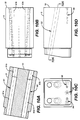
- a cavity design is illustrated in FIGs. 10a (plan view illustrating oxidant cavities only), 10b (plan view illustrating fuel and oxidant cavities), 10c (back end elevation) and 10d (side elevation), in the case of the oxidant cavities.
- Each of the oxidant cavities 91 and 92 comprise two straight flow paths 91a and 92a, initially parallel, that make a small outward angle near the exit (flow paths). The purpose of the small angle is to direct the flow of oxidant outwards, in a similar fashion as the jets of fuel gas.
- angling out the oxidant (in the tests oxygen was used) cavities proved to give more stability to the flame and is beneficial to the burner operation by widening flame width without significantly decreasing flame length.
- a preferred configuration is when the angle between the two oxidant cavities at their exits is equal to the angle between the two side fuel gas cavities.
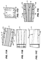
- FIGs. 11a-e is similar to the embodiment illustrated in FIG. 10, except that FIG. 11e illustrates that the two side fuel injectors make a small angle outward near their exit; thus both of the oxidant cavities 91b and 92b veer outward near exit face 10, as well as the two side fuel injectors 94b and 98b.
- the oxygen cavities are preferably angled downward toward the natural gas cavities.
- the angle shown on the drawings is 10 degrees. Under certain conditions, a smaller angle (such as 7.5 degrees) can be used. Again angling out the last few inches of the cavities is enough to impart a converging angle between the oxygen jets and the natural jets.
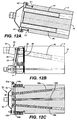
- the burner assembly illustrated in FIG. 12 includes a mounting bracket made of two parts that are positioned on each of the upper and lower portions of refractory block 5, fastened together by bolts 32 screwed in plate P.
- the mounting bracket assembly slides in vertical grooves G 1 and G2 in the refractory block, and is thus well anchored to the block once the bolts 60 and 61 are in place.
- An oxidant distributor 30 of FIG. 12 is mounted directly on the mounting bracket assembly with bolts 32 and plate 34. Tightness between the distributor and the block is insured by a gasket 36.
- the distributor comprises a plate 38 on which oxidant injectors 40 and 41 are welded. When mounted on the burner, the oxidant injectors penetrate into cavities in burner block 5, and stop 10 cm (4 inches) away from exit face 10 of the block, before any change in direction of the flow that can be imparted by the geometry of the oxidant cavities.
- a fuel gas distributor 50 is mounted on a plate 52 with quick connect clamps 53a and 53b.
- Plate 52 is attached to the mounting bracket by bolts 54a and 54b.
- Tightness between plate 52 and refractory block 5 is insured by a gasket 56.
- Three gas injectors 58a, 58b, and 58c penetrate into refractory block 5, and stop 10 cm (4 inches) away from exit face 10 of block 5 before any change in direction of the flow that can be imparted by the geometry of the fuel gas cavities.
- the inlet heads of the fuel gas injectors are imprisoned between the injector 60 and plate 52.
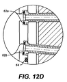
- Fuel gas injector tightness is insured by O-rings 62 and 64 positioned on the inlet head of the fuel gas injectors.
- the tube sealing detail in Figure 12(d) is noted, in particular.
- FIG. 13a is a perspective view of a refractory block 5 useful in the invention, illustrating the exits of two oxidant cavities 91a and 91b, the exits of three fuel gas cavities 94a, 94b, and 94c, and the exit of one liquid fuel cavity 95.
- FIG. 13b is a gas exit end elevation view of the refractory block of FIG 13b, illustrating distances d 1 and d2, wherein d2 is the distance between a plane containing the axial center of the two oxidant cavities 91 (second plane) and the liquid fuel cavity 95, and d 1 is the distance between the second plane and a plane containing the three fuel gas cavities 94. (Note that d 1 is the same distance as h in FIG. 2) FIG.
- 13c is a gas exit end elevation view of an alternate design for the refractory block of FIG. 13a, illustrating an embodiment wherein there are in fact no gaseous fuel exits, and only one liquid fuel exit 97 is present (the two oxidant gas exits are the same as in FIG 13a).
- d 2 d 1 ⁇ FO / ⁇ NG [(I FO + I AIR )/I NG ] (10 -3 ) wherein:
- FIG. 14 is a side elevation view of a burner assembly without a refractory block, having only oxidant injectors 102 and fuel injectors 104 inserted through and secured in a wall 100 of a furnace or glass melt tank, in accordance with another burner assembly embodiment of the present invention.
- the oxidant injectors are illustrated as being straight, with no change in angle, but of course the injectors may initially be parallel with the fuel injectors, and then change direction, so that the fuel and oxidant mix in the combustion chamber.
- This embodiment may also be used when the fuel is a liquid fuel.
- This arrangement, as well as the embodiment illustrated in FIG. 17, may be useful in that the fuel and oxidant may be preheated by combusted fuel in the combustion chamber, adding to the efficiency of fuel combustion.
- FIG. 15 is a plan view of a refractory block, illustrating cavities (oxidant or fuel) 91a and 91b;
- FIG. 16 is a plan view of the refractory block of FIG. 15, illustrating an embodiment having short injectors 102a and 102b inside the cavities;
- FIG. 17 is a plan view of the refractory block of FIG. 15, illustrating an embodiment having long injectors 102a and 102b protruding outside of the cavities.
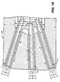
- FIG. 18 is a sectional view of a liquid fuel atomizer 200 useful in the invention.
- the present aspect of the invention falls within the scope of the third mode of liquid fuel atomization; it describes a complete device that makes possible control of the atomization of a liquid fuel using a gaseous fluid and the application of this device to a burner, such as the inventive burner assemblies described herein.
- the fluid introduction into the combustion zone is a two-phase mixture of atomizing gas and droplets of liquid fuel.
- specific characteristics of the invention reside in the fact that atomization takes place outside of the nozzle (external atomization) and yet permits forming distinct spray jets having high relative angles (5° to 30°).
- the inventive liquid fuel atomizer is capable of ensuring the production of a single broad flame, a single long flame, or several short flames simultaneously.
- the atomization principle adopted in the atomizer of the present invention is external atomization. This choice was essentially imposed by the constraints of thermal resistance and maintenance of the injector when used in a third generation burner (self-cooled burner with separate injection). In effect, the temperature levels potentially reached by the fuel injectors in burners of this type and very much higher than those previously encountered with first and second generation burners.
- the liquid fuel is constantly "sheathed" by the atomizing fluid, which, being heated preferentially, draws off the heat flux transmitted to the injector.
- the atomizing fluid thus protects the liquid fuel from any excessive heating that could produce the beginnings of coke formation.
- this outer nozzle is composed of two symmetrical cowls which, when they are positioned face to face, completely enclose the liquid fuel injector and form the outer nozzle.
- the liquid fuel injector 200 is composed of a hollow cylinder of inside diameter D OI and outside diameter D OE that is terminated with a certain number of hollow elementary conduits C 1 , C 2 , and C 3 .
- Liquid fuel is delivered into the cylinder of diameter D OI and then to the interior of all the hollow conduits to emerge outside the liquid fuel injector (combustion chamber side).
- the number of elementary conduits can range from 2 to 5 (typically 2 or 3).
- the axes of all the elementary conduits are in the same plane ("spray plane"); this plane contains the axis of the hollow cylinder (D OI ; D OE ).
- Each of the hollow conduits will have an inside diameter D i 1 (into which the liquid fuel will flow) and an outside “diameter” D i 2 .
- the external shape of the conduits is not necessarily cylindrical: it can be parallelepipedal with square section. In such a case, D i 2 is the side of the square, the side parallel to the "spray plane.”
- Each of these conduits has an inclination angle ⁇ i 1 with respect to the axis of the cylinder (D OI ; D OE ); this angle is in the "spray plane.”
- each of these conduits is L i 1 .
- the outer nozzle is formed of a hollow cylinder (inside diameter D FI and outside diameter D FE ) which is extended by a profiled part.
- the interior of the profiled part of the nozzle is pierced by channels which merge with the cylinder of diameter D FI .
- the number of channels is equal to the number of elementary conduits present in the liquid fuel injector. All the axes of these channels are located in the "spray plane", which also contains the axis of the cylinder (D FI ; D FE ).
- the channels have a length L i 2 and a diameter D i 3 .
- the shape of the channels is the same as that of the elementary conduits of the fuel injector: it can be cylindrical or parallelepipedal with square section (in the former case, D i 3 is the diameter of the cylinder; in the latter case D i 3 is the length of the side of the square, the side parallel to the "spray plane").
- Each of these channels has an inclination angle I i 2 with respect to the axis of the hollow cylinder (D FI ; D FE ); this angle is in the "spray plane.”
- the axis of the hollow cylinder coincides with that of the hollow cylinder (D FI ; D FE ).
- the atomizing fluid is delivered to the interior of the outer nozzle and around the liquid fuel injector.
- An elementary atomizer is comprised of
- this thickness must be sufficient to provide mechanical resistance to the shocks that occur during manipulation of the atomization device.
- D i 2 - D i 1 ⁇ 6 mm, and typically and preferably D i 2 - D i 1 1 mm.
- V atomizing fluid The space between the outside of the hollow conduit and the inside of the channel ("the flame") must be proportioned in such a way that the velocity of the atomizing fluid (V atomizing fluid ) follows the relationship: Mach 0.3 ⁇ V atomizing fluid ⁇ Mach 1.2 .
- each of the elementary atomizers is to eject a spray of droplets in a precise direction. This direction is the direction of the axis of the channel and the hollow conduit for liquid fuel.
- the length of the hollow conduit and the length of the channel must be sufficient to secure establishment of the flows of the two fluids in their respective conduits.
- D i 1 values specific to each of the elementary conduits.
- the large D i 1 is, the more fuel will be carried by elementary atomizer i.
- the relative angle between the different elementary atomizers is a function of the number of elementary atomizers composing the atomization device and the flame morphology one wishes to obtain.
- the atomization device of the invention In the case of continuous use of this device in glass furnaces (combustion chambers with elevated temperatures ranging from 1500°C to 1670°C the atomization device of the invention must be capable of ensuring production of a stable flame for periods on the order of months.
- the atomization principle selected makes it possible to keep the temperature of the metal parts composing the device below 1100°C. Thus, the temperature measured at the tip of the device during an industrial test for one month in a glass furnace at 1600°C never exceeded 800°C.
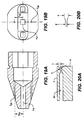
- two symmetrical orifices are provided in the nozzle (FIG. 19a and FIG 19b).
- the diameter D OR and the elevation H OR are established in such a way that the jet of atomizing fluid emerging from the orifices covers the entire surface of the end of the outer nozzle.
- D OR ⁇ 1 mm and H OR ⁇ 10 mm typically, D OR ⁇ 1 mm and H OR ⁇ 10 mm.
- a small slot e FF ⁇ 0.1mm has to be made between the outer nozzles.
- the atomization device of the present invention it is possible to significantly vary the length of the flame (or flames) produced by a burner using this device.
- the flexibility (in terms of flame length at constant fuel delivery rate) observed when this device is deployed in a glass furnace corresponds to a ratio of one to three (flame length varying from 3.7 to 1.2 m).
- This control of the flame length is achieved by increasing or decreasing the delivery rate of the atomizing fluid flowing between the outer nozzle and the liquid fuel injector. This variation in delivery rate is directly linked to the variation in pressure of the atomizing fluid upstream from the atomization device.
- this device functions at an atomizing fluid pressure between 1 and 6 bars relative.
- This phenomenon is directly attributable to the change in the particle size distribution of the droplets of liquid fuel composing the spray that is formed: the increase in the rate of delivery of atomizing fluid has the effect of decreasing the average spray droplet diameter and narrowing the distribution of the diameters about this mean value. Conversely, a decrease in the rate of delivery of atomizing fluid will increase the average diameter while widening the distribution.
- Preferred pressurized atomization fluids are employed, such as pressurized air, steam, water vapor, and the like.
- FIG. 20a is a schematic illustration of a refractory block 5 and fuel gas cavity 94 in same, while FIG. 20b is a schematic illustrating a cavity throat diameter D' and gas exit diameter D for an injector or cavity.
- the ratio of 1 (from FIG. 2, the distance between adjacent fuel gas exits) and D' (fuel cavity or injector throat diameter) ranges from 1.5 to 10, more preferably from 1.5 to 3, and most preferably 2.
- FIG. 20a also illustrates that the cavities in the refractory block may have varying diameter in the direction of gas flow, and that the gas exits are generally contoured at the exits, allowing the exits to be less likely to be plugged.
- FIGs. 21 and 22 are gas exit end elevation views of two other refractory block embodiments within the invention, illustrating oxidant cavities 91a and 91b.
- the embodiment of FIG. 21 illustrates that the fuel gas cavities 94 may have concentric gas injectors in each cavity, whereby for example, fuel may injected in small diameter fuel gas injector 94' for low power operation, and through either the large diameter fuel gas injector 94 only, or through both injectors 94 and 94' for high power burner operation. Control of fuel flow between 94 and 94' may be controlled by suitable valving arrangements, or through the use of an orifice in the line feeding one or the other of 94 and 94'.
- a liquid fuel injector 95 is also illustrated.
- FIG. 22 illustrates a very important alternative refractory block embodiment within the invention, wherein it has been discovered that flame stability is significantly increased when the peripheral oxidant injectors 91a and 91b, when positioned as illustrated, have a distance separating them of L, is greater than two times the distance l between adjacent fuel injectors, that is when L > 21. This is true also when the fuel and oxidant are injected via the use only of injectors, rather than the use of a refractory block.
- FIGs. 23-31 illustrate, in front elevation views, other embodiments of burner assemblies of the invention.
- FIG. 23 illustrates an embodiment wherein the two oxidant cavities 91a and 91b have exits which are rectangular, also illustrating three fuel gas exits 94 and a liquid fuel exit 95.
- FIG. 24 illustrates an embodiment wherein oxidant emanates from two oxidant exits 91a and 91b, and oxidant also emanates from three annular portions 91' which surround respectively three fuel exits 94'.
- FIG. 25 illustrates an embodiment wherein a single oxidant exit 91 is present as a rectangle having a width much greater than its height.
- the ratio of width to height of the oxidant cavity exit may range from 1:1 up to 4:1.
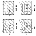
- FIG. 26 illustrates an embodiment wherein the two oxidant cavities 91a and 91b have exits which are ellipsoid, also illustrating three fuel gas exits 94.
- FIG. 27 illustrates an embodiment similar to the embodiemnt of FIG. 26, with the addition of a liquid fuel cavity 95 having a circular exit.
- FIG. 28 illustrates an embodiment wherein a single ellipsoid oxidant exit 91 is present with three fuel gas cavities 94 having circular exits.
- FIG. 29 illustrates an embodiment similar to the embodiment of FIG. 28, with the addition of a liquid fuel cavity 95 having a circular exit.
- FIG. 30 illustrates an embodiment wherein a single ellipsoid oxidant exit 91 is present with two fuel gas cavities 94 having circular exits.
- FIG. 31 illustrates an embodiment similar to the embodiemnt of FIG. 30 wherein a single ellipsoid oxidant exit 91 is present with two fuel gas cavities 94 having circular exits, with the addition of a liquid fuel cavity 95 having a circular exit.
- FIGs. 32 and 33 illustrate embodiments wherein oxidant emanates from one or more positions both above and below the fuel exit(s).
- the fuel cavities are essentially parallel to the lower oxidant cavities, while the upper oxidant cavities are angled down so that the upper oxidant fluid flow converges with the fuel fluid flow and the lower oxidant fluid flows in the combustion chamber.
- duel oxidant exits 91a and 91b are positioned above and below, respectively, of a single fuel exit 94.
- FIG. 33 illustrates a similar embodiment, except that there are two oxidant exits 91a and 91b above two fuel exits 94, and two oxidant exits 91a' and 91b' below the duel fuel exits. More than two fuel exits, with corresponding upper and lower oxidant exits, can be envisioned.
- exits of oxidant and fuel in all embodiments are preferably contoured, as depicted for example in FIGs. 8-11.
Landscapes
- Engineering & Computer Science (AREA)
- Chemical & Material Sciences (AREA)
- Combustion & Propulsion (AREA)
- Mechanical Engineering (AREA)
- General Engineering & Computer Science (AREA)
- Materials Engineering (AREA)
- Organic Chemistry (AREA)
- Combustion Of Fluid Fuel (AREA)
- Pre-Mixing And Non-Premixing Gas Burner (AREA)
- Air Supply (AREA)
- Nozzles For Spraying Of Liquid Fuel (AREA)
Abstract
Description
- The present invention relates to a combustion process and an apparatus therefor containing separate injectors to introduce separately a fuel and an oxidant in the combustion chamber of a furnace, so that the fuel burns with the oxidant in a wide luminous flame, and whereby the combustion of the fuel with the oxidant generates reduced quantities of nitrogen oxides (NOx).
- Industrial high temperature processes, such as glass or frit melting, ferrous and non ferrous materials smelting, use large amounts of energy to transform a variety of raw materials into a hot molten product, that is then casted, formed or otherwise disposed of in further stages of the industrial process. This operation is generally performed in large furnaces, that can produce as much as 500 tons (metric) per day of molten material. Combustion in the furnace of a fossil fuel, such as natural gas, atomized fuel oil, propane, or the like, with an oxidant that contains oxygen is a preferred method of supplying the energy. In some cases, the combustion is supplemented by electric heating. Most of the time, the fuel and the oxidant are introduced in the furnace through burners, in order to generate flames. The transfer of energy from the flames to the material to be melted results from the combination of convection at the surface of the material, and radiation to the surface or into the material if it is transparent to the radiation. Flames that are highly radiative (usually referred to as luminous flames), are usually preferred, because they provide better heat transfer and, thus, higher fuel efficiency.
- For flame heating, it is also very important to have the energy from the flame evenly distributed above the surface of the material to be melted. Otherwise, hot and cold regions may co-exist in the furnace, which is not desirable. The quality of products manufactured with material melted in such a furnace is often poor. For example, in a bath of molten glass, there may be glass stones in cold regions, and accelerated volatilization of glass in hot regions. Also, broad flames are preferred because they yield a better bath coverage.
- In many countries, particularly the United States, increasingly stringent regulations are being promulgated regarding emissions of NOx. It is, therefore, important to develop combustion techniques wherein NOx formation is limited. In very high temperature processes, NOx formation is promoted by long residence times of oxygen and nitrogen molecules in hot regions of the flame and the furnace. The use of substantially pure oxygen (90% O2 or higher) instead of air as the oxidant has proven to be very successful in reducing the NOx emissions by as much as 90%, since all nitrogen is eliminated. However, substitution of air by substantially pure oxygen increases the flame temperature, and thus creates regions in the furnace where the reactivity of nitrogen with oxygen is high, and wherein the formation of NOx may proportionally increase, even though it is globally decreased when compared to combustion with air. Also, it is impossible in practice to eliminate all nitrogen from a furnace, because industrial furnaces are not tight to air leaks, the fuel usually contains some nitrogen, and oxygen supplied from non-cryogenic sources, such as oxygen produced by a Vacuum Swing Adsorption plant (VSA), contains a small residual nitrogen concentration.
- Conventional methods of combusting fuel and oxygen for heating furnaces utilize post mix oxy-fuel burners. Conventional oxy-fuel burners have a metallic body with inlets for a fuel and an oxidant with a high concentration of molecular oxygen, and means to transport the streams with separate coaxially oriented channels to multiple injectors located at the burner tip. These burners generate high temperature flames with the shape of a narrow pencil at the burner tip, which needs to be located far enough into the furnace, to avoid or reduce overheating of the furnace walls. As a consequence of the high temperatures encountered in melting furnaces, one important drawback of these burners is the need for cooling, usually a jacket where a circulating fluid such as water provides the cooling. Such a burner is described, for example, in British Patent 1,215,925. Severe corrosion problems for the cooling jacket can arise particularly when the furnace atmosphere contains condensable vapors.
- The gas cooled oxy-fuel burner is an improvement of the water-cooled burner. The body of the burner is protected from the furnace radiation by a refractory brick often referred to as a burner block, that possesses a substantially cylindrical cavity that opens into the furnace. The burner is usually mounted at the back of the cavity, and it usually contains concentric injectors of fuel and oxidant located in the cavity, recessed from the furnace inner wall. The brick and the burner are cooled by a peripheral annular flow of gas, usually the oxidant gas. Such burners are described e.g. in USP 5,346,390 and USP 5,267,850. With this type of burner, combustion starts in the burner block before reaching the furnace. Thus, the flame is confined in and directed by the cylindrical cavity as a narrow axisymmetric jet, and provides insufficient covering of the melt in the furnace. These flames have high peak temperatures and generate relatively large amounts of NOx, because there is a direct contact between the oxygen and the fuel without dilution by the combustion products.
- Another drawback of these gas cooled burners is that the flame may overheat and damage the furnace refractory wall because it starts in the wall itself. Also recirculation zones under the flame itself tend to accelerate refractory wear when the furnace atmosphere chemically reacts with the refractory material of the furnace wall which may reduce the furnace lifetime.
- British Patent 1,074,826 and USP 5,299,929 disclose burners containing alternated multiple oxygen and fuel injectors in parallel rows in order to obtain a flatter flame. Although this brings an improvement in terms of coverage of the melt, these burners still produce relatively large amounts of NOx. Another drawback of these burners is that they are mechanically complex to build in order to obtain a flat flame.
- It is also known to inject fuel and oxidant by streams separate distant injectors into a combustion chamber to generate flames detached from the furnace wall, with the aim of reducing refractory wear. One such apparatus is described in USP 5,302,112 wherein fuel and oxidant jets are injected at a converging angle into a furnace, which yields good mixing of the oxidant and fuel gases at the converging point of the two jets, thus enhancing the combustion rate but shortening the flame. However, the flame of such a burner has a high peak temperature and large quantities of nitrogen oxides are created in the furnace. To decrease this high peak temperature and significantly reduce formation of NOx it has been suggested in USP 4,378,205 to inject the fuel and/or the oxidant jets at very high velocities and to use separate injections of fuel and oxidant gases wherein the fuel and/or the oxidant jets entrain combustion products contained in the furnace atmosphere, and are diluted before the actual combustion between the fuel and the oxidant. However, the flames generated by these burners are almost invisible, as disclosed therein, col. 9, lines 58-65. It is, thus, extremely difficult for a furnace operator to determine and/or control the location of the combustion zones, and whether or not the burner apparatus is actually turned on, which may be hazardous. Another drawback of this burner is that the entrainment of combustion products promotes strong recirculation streams of gases in the furnace, which in turn accelerates the wear of the refractory walls of the furnace. Also, the use of high velocity oxidant jets requires the use of a high pressure oxidant supply, which means that the oxidant gas needs to be either produced or delivered at high pressure (the fuel gas is usually at relatively high pressure) or that the oxidant gas, such as the low pressure oxygen gas usually supplied by a VSA unit, has to be recompressed before being injected into the furnace.
- Burners in use today typically are only designed to use gaseous fuel or liquid fuels (perhaps by spray of the liquid fuel), but cannot burn both types of fuel simultaneously, or switch easily from gaseous fuel to liquid fuel.
- Liquid fuels present their own problems to the combustion artisan. The liquid fuel is typically atomized, and there are several different techniques available for the atomization of liquid fluids. The object is to produce jets of liquid fluid droplets (also called "spray") which have defined geometric characteristics. The usual liquid fuels are not particularly flammable in the liquid state: only in the gaseous state are they able to support an oxidation reaction sufficiently rapid to give rise to the appearance of a flame. When one wishes to obtain stable flames with fuels that are liquid or viscous at ambient temperature, the principal difficulty is thus to "shrewdly condition" this liquid in such a way that it evaporates rapidly in order to support oxidation reactions in the interior of the flame.
- The method currently used to achieve this "shrewd conditioning" consists of atomizing the fuel in the form of droplets: thus, for a given quantity of fuel, this makes possible a substantial increase in the amount of liquid surface exposed to the oxidant (the smaller the drops are, the greater will be the interfacial surface -- the site of evaporation).
- In simplified terms there are three major methods for achieving atomization of a liquid:
- 1. rotating cup atomization involves shredding the fluid with the air of a moving mechanical element.
- 2. in mechanical atomization the fuel is compressed to very high pressures (15 to 30 bars), thus imparting to it a high kinetic energy. This energy results in shearing of the liquid when it is brought into contact with the exterior atmosphere and thus results in the formation of droplets.
- 3. gaseous-fluid-assisted atomization can be used to arrive at a similar result while achieving a saving on high pressures (2 to 6 bars).
- In simplified terms one can distinguish two types of gaseous-fluid- assisted atomization according to whether the liquid fuel and atomizing fluid are brought into contact inside or outside the atomizer head. These types may be referred to as internal atomization and external atomization.
- Internal atomization is characterized by confinement of the liquid fuel and atomizing fluid in an emulsion chamber. The mode of introduction of the two fluids into this chamber can vary considerably and has a direct influence on the characteristics of the emulsion that exits from the chamber. Likewise, the internal geometry of this chamber (overall volume, vanes for producing rotation, number and diameters of the inlet and outlet orifices, and so forth) also affects the specific characteristics of the fuel/atomizing fluid mixture to be burned.
- This mode of atomization generally affords an excellent quality of atomization, that is, an emulsion composed of very small particles with a very narrow particle size distribution about these small diameters. At a given fuel delivery rate, this emulsion quality is naturally a function of the atomizing fluid delivery rate employed and the pressure level prevailing in the interior of the atomizing chamber.
- For external atomization, where contact between the two phases takes place outside of any confining enclosure, the emulsion is created mainly by shearing of the jet of liquid fuel by the atomizing fluid. The geometry of the outlets for the two fluids completely determines the quality of the atomization, and particle size analysis of the drops resulting from the contact shows a relatively wide diameter distribution (simultaneous presence of small and large particles).
- In the field of liquid fuel atomization, the principal known priority for the invention is published European Patent Application No. 0687858 Al, which claims an external atomization device that produces a very narrow spray angle (less than 15°). This published application in particular claims that to successfully achieve this specific characteristic the angle formed between the atomizing fluid and the liquid fuel must be between 5° and 30°.
- Another disclosed liquid fuel atomization device is the one disclosed in European Patent Application No. 0335728 A3, which claims a device for the introduction of a fluid into a combustion enclosure through the expedient of several distinct conduits branching from a common main conduit.
- A need exists for a burner which may operate at low pressure, particularly for the oxidant gas, while producing a wide, flat luminous flame with reduced NOx emissions, and which affords a manner of controlling flame length so as to adapt the flame to the furnace in which it is used. There also exists a need in the art for a burner having the capability of burning gaseous fuels and liquid fuels, either at the same time or in the alternative. There is a need in the combustion art for a liquid fuel atomizer that falls within the scope of the third mode of atomization, a complete device that makes possible a controlled fluid introduction into the combustion zone that is a two-phase mixture of atomizing gas and droplets of liquid fuel, wherein atomization takes place outside of the nozzle (external atomization) and yet permits forming distinct spray jets having high relative angles (5° to 30°). In particular the combustion art is desirous of a device for atomization of a liquid fuel using a gaseous fluid and the application of this device to a burner such as the burner assemblies described herein.
- In accordance with the present invention, methods and systems for combustion of a fuel with oxygen contained in an oxidant gas are presented, wherein the fuel and oxidant gas are injected in separate fluid streams into a combustion chamber of a high temperature furnace (having a temperature of at least, 820°C or 1500°F) in such proportions that the molar ratio of oxygen in the oxidant flow to fuel flow is between 0.95 and 1.05 (stoichiometric ratio), the fuel and oxidant producing a wide, luminous, well-defined flame. Methods and systems of the present invention generate reduced quantities of NOx.
- In general, the inventive burner assembly is characterized by at least one fuel fluid inlet and at least one oxidant fluid inlet, means for transporting the fuel fluid from the fuel inlet to a plurality of fuel outlets, the fuel fluid leaving the fuel outlets in fuel streams that are injected into a combustion chamber, means for transporting the oxidant fluid from the oxidant inlets to at least one oxidant outlet, the oxidant fluid leaving the oxidant outlets in oxidant fluid streams that are injected into the combustion chamber, with the fuel and oxidant outlets being physically separated, and geometrically arranged in order to impart to the fuel fluid streams and the oxidant fluid streams angles (referred to herein as "final" angles) and velocities (as the fuel and oxidant enter the combustion chamber) that allow combustion of the fuel fluid with the oxidant in a stable, wide, and luminous flame.
- Thus, one aspect of the invention is a burner assembly having improved flame length and shape control, characterized by:
a refractory block adapted to be in fluid connection with sources of oxidant and fuel, the refractory block having a fuel and oxidant entrance end and a fuel and oxidant exit end, the exit end having fuel exits and oxidant exits, the refractory block further having a plurality of fuel cavities, at least two of the fuel cavities defining a first fuel plane, and a plurality of oxidant cavities defining a second oxidant plane, the fuel cavities being more numerous than the oxidant cavities. - Preferred are burner assemblies of this aspect of the invention wherein the oxidant exits are larger than the fuel exits, and embodiments wherein one or more cavities has therein an injector positioned therein, as defined herein.
- Preferred refractory blocks have at least five cavities, three cavities at a lower portion thereof for injection of fuel into a furnace combustion chamber, and two cavities at an upper portion thereof for injection of an oxidant into a furnace combustion chamber.
- Alternatively, especially in the case when liquid fuels such as fuel oil is used as the fuel, the oxidant cavities are preferably more numerous than the fuel cavities.
- In a particularly preferred embodiment ( a so-called "bi-fuel" embodiment), the refractory block has at least one liquid fuel cavity and at least one gaseous fuel cavity. In these embodiments, it is preferred that the liquid fuel cavity be positioned below that gaseous fuel cavities, and the gaseous fuel cavities positioned below the oxidant cavities, as further described herein.
- Preferably, the fuel and oxidant exits are circular and contoured. The cavities are preferably straight holes through the refractory block form a fluid entrance end of the block to a fluid exit end of the block. The burner assembly of the invention may in some preferred embodiments comprise a fuel distributor or atomizer which is a single, integral component which fits inside a cavity of the refractory block, the fuel distributor having multiple fuel exits.
- Another burner assembly embodiment of the invention is that characterized by a refractory block having a fuel and oxidant entrance end and a fuel and oxidant exit end, and further having a single liquid fuel cavity and a plurality of oxidant cavities, the oxidant cavities defining an oxidant plane which is positioned at an upper portion of the refractory block and above the liquid fuel cavity.
- Yet another burner assembly of the invention is characterized by a refractory block having a fuel and oxidant entrance end and a fuel and oxidant exit end, and further having a plurality of fuel cavities and a plurality of oxidant cavities, at least two of the oxidant cavities defining a first oxidant plane which is positioned at an upper portion of the refractory block and above a portion of the fuel cavities defining a fuel plane, wherein at least some of the oxidant cavities form a second plane at a position lower in the refractory block than the first oxidant plane, and wherein at least one of the oxidant cavities in the second oxidant plane has positioned therein a fuel injector having a diameter smaller than its corresponding oxidant cavity.
- Another burner assembly embodiment of the invention is characterized by a refractory block having a fuel and oxidant entrance end and a fuel and oxidant exit end, and further having a plurality of fuel cavities and a single oxidant cavity, said oxidant cavity positioned at an upper portion of the refractory block and above a portion of the fuel cavities defining a fuel plane. The oxidant cavity itself (cross-section) and its exit may be non-circular, such as rectangular, oval, ellipsoidal, and the like, in all cases preferably with contoured edges at the block exit face as described herein.
- Another burner assembly of the invention is characterized by:
- a) at least two fuel injectors defining a first plane;
- b) at least one oxidant injector;
- c) a wall through which the oxidant and the fuel injectors protrude into a combustion chamber, the injectors removably secured in the wall;
- Another aspect of the invention is a method of combustion of a fuel with an oxidant, the method is characterized by:
- a) providing a supply of an oxidant fluid stream;
- b) injecting the oxidant fluid stream into a combustion chamber to create at least one injected oxidant fluid stream;
- c) providing a supply of a fuel fluid stream;
- d) injecting the fuel fluid stream into the combustion chamber to create at least two injected fuel fluid streams;
- e) creating a substantially planar sheet of fuel fluid in the combustion chamber by injecting the at least two injected fuel fluid streams into the combustion chamber, at least two of the injected fuel fluid streams being substantially located in a first fuel plane;
- f) intersecting the oxidant fluid stream with the sheet of fuel fluid in the combustion chamber; and
- g) combusting the fuel fluid with the oxidant fluid in the combustion chamber.
- In preferred processes in accordance with the invention, two adjacent fuel fluid streams have a final diverging angle which is not greater than 15°. Other preferred methods are those wherein gaseous and liquid fuels are burned simultaneously, and methods wherein gaseous fuel (or liquid fuel) is burned first, followed by liquid fuel (or gaseous fuel).
- It has been discovered that when the oxidant flow cavities are arranged in a diverging fashion the flame is wider. In some embodiments, the flame breadth can be increased (without significant decrease in the flame length) by providing the fuel and/or oxidant flow cavities with a final divergence angle slightly more than their initial divergence angle, as further described herein. Also, in some preferred embodiments, oxidant and fuel injectors are used (especially for fuel) which fit inside the fuel and/or oxidant cavities.
- Other embodiments of the method and apparatus of the invention include the provision of different distances between oxidant cavities and fuel cavities, depending on the type of fuel being burned (for example gaseous fuel vs. liquid fuel); non-parallel oxidant cavities (i.e. having diverging angles); and the provision, especially for fuel oil purposes, of a fuel injector having multiple diverging fuel sub-injectors, the fuel injector being located in one cavity of the refractory block.
- FIG. 1 illustrates one embodiment of a refractory block component of a burner assembly of the present invention, wherein the fuel "sheet" is made by using three (3) fuel injectors located in a first plane, and wherein the oxidant is supplied by two (2) injectors located in a second plane;
- FIG. 2 is a front view of the arrangement of FIG. 1;
- FIG. 3 is a schematic side view of the combustion process that occurs in a furnace when the configuration of FIGs. 1 or 2 is used;
- FIG. 4 is a top view of the process of FIG. 3;
- FIG. 5 illustrates a second burner assembly embodiment of the present invention, where the fuel "sheet" is formed by using two fuel cavities in a first fuel plane, the oxidant being supplied by two cavities in a second plane, and flame stabilization being supplied by an auxiliary fuel injection in the second plane;
- FIG. 6 illustrates a third burner assembly embodiment of the present invention, where the fuel "sheet" is formed by using two fuel cavities in a first fuel plane, the oxidant being supplied by two cavities in a second plane, and wherein the flame is being stabilized by an auxiliary oxidant cavity in the first fuel plane, between the fuel cavities.
- FIG. 7 illustrates a perspective view of one burner assembly embodiment of the present invention;
- FIGs. 8(a), (b) and (c) illustrate top, back and side views, respectively, of a burner assembly of the present invention including cavities;
- FIGs. 9 (a) and (b) illustrate a refractory block of the present invention, showing various cavities;
- FIGs. 10 (a), (b), (c) and (d) illustrate a burner block assembly, oxygen distributor and fuel distributor of the present invention;
- FIGs. 11 (a), (b), (c), (d), and (e) illustrate another burner block assembly, oxygen distributor and fuel distributor of the present invention;
- FIGs. 12 (a), (b), (c) and (d) illustrate a burner assembly of the invention in top, side, bottom, and detail views, showing in particular, the tube sealing detail;
- FIG. 13a is a perspective view of a refractory block useful in the invention, illustrating two oxidant cavities, three fuel gas cavities, and one fuel oil cavity;
- FIG. 13b is a side elevation view of the refractory block of FIG 13b;
- FIG. 13c is a side elevation view of an alternate design for the refractory block of FIG. 13a;
- FIG. 14 is a side elevation view of a burner assembly without a refractory block, having only oxidant and fuel injectors;
- FIG. 15 is a plan view of a refractory block, illustrating cavities;
- FIG. 16 is a plan view of the refractory block of FIG. 15, illustrating an embodiment having short injectors inside the cavities;
- FIG. 17 is a plan view of the refractory block of FIG. 15, illustrating an embodiment having long injectors protruding outside of the cavities;
- FIG. 18 is a side elevation view of a liquid fuel atomizer useful in the invention;
- FIGS. 19a and 19b are sectional and front end elevation views, respectively, of the liquid fuel atomizer of FIG. 18;
- FIG. 20a is a schematic illustration of a refractory block and cavity in same;
- FIG. 20b is a schematic illustrating a preferred relationship between throat diameter and gas exit diameter for an injector or cavity; and
- FIGs. 21, 22, 23, 24, 25, 26, 27, 28, 29, 30, 31, 32, and 33 are front elevation views of thirteen refractory block embodiments within the invention.
- According to one aspect of the present invention, the combustion process and apparatus therefor are provided which operates with low oxidant supply pressure, such as the pressure delivered by a vacuum swing adsorption oxygen production unit. Low oxidant pressure means a pressure ranging from 105,000 to 170,000 Pa (absolute pressure) (50 m bar to 0.7 bar/relative pressure).
- According to the present invention, the fuel and the oxidant are introduced in the furnace through separate cavities in the burner assembly. The term "fuel", according to this invention, means, for example, methane, natural gas, liquefied natural gas, propane, atomized oil or the like (either in gaseous or liquid form) at either room temperature (25°C) or in preheated form. The term "oxidant", according to the present invention, means a gas with an oxygen molar concentration of at least 50%. Such oxidants include oxygen-enriched air containing at least 50% vol., oxygen such as "industrially" pure oxygen (99.5%) produced by a cryogenic air separation plant or non-pure oxygen produced by e.g. a vacuum swing adsorption process (88% vol. O2 or more) or "impure" oxygen produced from air or any other source by filtration, adsorption, absorption, membrane separation, or the like, at either room temperature or in preheated form.
- The cavities, as defined herein, are passages through a ceramic block or through a furnace wall, and preferably have a generally cylindrical cross section. Any equivalent cross section can be used, such as square, rectangular, ellipsoid, oval, and the like. Injectors are defined herein as tubular members having an outer shape which mates with its respective cavity, and which can be placed in its respective cavity to prolong the use of the refractory burner block. Injectors can be either metallic tubes, metallic tubes or pipes with ceramic ends, ceramic tubes, or a combination thereof. Examples of suitable ceramic materials for injector tubes include alumina, zirconia, yttria, silicon carbide, and the like. Various stainless steels may be used for the injectors if the injectors are metallic, and metallic injectors having heat-protective refractory coatings, employing materials such as those mentioned for ceramic injectors, are also possible.
- Injectors are preferred but not absolutely necessary. For example, injectors would not be necessary if the cavities are covered or coated with a layer of ceramic or any other material which withstands the high temperature and has adequate non-porosity to avoid penetration of gas through the refractory block
- The injectors are installed in cavities opened through the furnace walls, or through a refractory or ceramic brick mounted in the furnace wall. In some embodiments, the length of the injector is purposely made insufficient to span the respective length of its cavity in the burner block: the fuel or oxidant flows from the injector into the cavity, then from the cavity into the combustion chamber of the furnace. Thus, in some embodiments, the injector stops before any change in direction of the gas flow that can be imparted by the geometry of the cavity; in other embodiments, the injector may protrude out of the refractory block and into the combustion chamber. In other embodiments there may be no injectors at all.
- The fuel injection is preferably made by at least two, preferably identical, cavities which axis are located preferably in a same plane, further referred to as the first fuel plane. The fuel and oxidant outlets are physically separated and geometrically arranged in order to impart to the fuel fluid streams and the oxidant fluid streams angles and velocities that allow combustion of the fuel fluid with the oxidant in a stable, wide, and luminous flame.
- In preferred embodiments, the fuel cavities diverge at an initial angle, and then this initial divergence angle increases slightly just before the fuel enters the combustion chamber to the final divergence angle. This final divergence angle is preferably only a few degrees larger than the first divergence angle. A preferred final angle between two adjacent fuel cavities is between 3 and 10 degrees. The distance 1 between the extremities of the cavities when the fuel enters the combustion chamber of the furnace is comprised preferably between 4 and 10 times the inner diameter d of each fuel injector in the first plane. The first plane is preferably but not necessarily parallel to the melt surface. When the fuel injector or cavity is not circular, the dimension "d" is an equivalent diameter corresponding to the cross-sectional area of an equalivalent circular injector or cavity. The combination of the fuel jets from the fuel cavities is such that it creates a fuel "sheet". By fuel "sheet", it is meant a substantially continuous cloud of fuel droplets (if liquid) or fuel gas in an angle of the first plane of at most 120°, preferably between 20° and 60°, and preferably symmetrical relative to the longitudinal axis of symmetry of the fuel cavities. The velocity of the fuel gas in the cavities is preferably at least 15 m/s.
- According to one preferred embodiment of the present invention, a process is provided wherein a "sheet" of fuel fluid is generated above the surface to be heated, e.g. by means of at least two fuel cavities that make a final diverging angle preferably smaller than 15 degrees, said fuel cavities being located in a first plane, an oxidant fluid having a lower velocity than that of the fuel fluid (preferably not exceeding 60 meters per second (m/s) being injected above the surface to be heated, preferably with at least two oxygen cavities, two adjacent oxygen cavities making a final diverging angle smaller than 15 degrees. These cavities are preferably located in a second plane, which converges to and intersects with the first plane in the combustion chamber. The low velocity oxidant fluid jets which intersect with the fuel sheet, are dragged by the fuel flow along the fuel sheet, and create a combustion zone that stretches along the "sheet". Accordingly, at the beginning of the combustion zone of the combustion chamber, a fuel-rich region is maintained at the underside of the fuel cloud where significant amounts of soot are formed. The soot and the fuel are then progressively oxidized by the oxidant that diffuses along the combustion zone.
- According to a particular embodiment of the invention, a method of combustion in a combustion zone is provided for a burner assembly containing at least two fuel fluid cavities, at least one oxidant fluid cavity and at least one exit face at which the fuel fluid cavities and oxidant fluid cavity terminates, the process entailing:
- providing a supply of an oxidant fluid stream;
- injecting said oxidant fluid stream through said at least one oxidant fluid cavity to create at least one injected oxidant fluid stream;
- providing a supply of a fuel fluid stream;
- injecting said fuel fluid stream through said at least two fuel fluid cavities to create at least two injected fuel fluid streams;
- creating a substantially planar sheet of fuel fluid by injecting the at least two injected fuel fluid streams with a final diverging angle, at least two injected fuel fluid streams being substantially located in a first fuel plane;
- intersecting the oxidant fluid stream with the sheet of fuel fluid in the combustion zone; and
- combusting the oxidant fluid with the fuel fluid in the combustion zone.
- Additionally, the invention also provides stabilization of the flame with an auxiliary injection of fuel and/or oxidant gases.
- According to another embodiment of the invention, it is possible to also have additional fuel cavities, e.g. located in a second fuel plane, beneath the first fuel plane and preferably parallel to or slightly converging with the first fuel plane.
- The injection of the oxidant fluid is made by at least two, preferably identical, cavities whose axis are located in the same plane, namely a first oxidant plane. The axial distance L between the tips of the oxidant cavities where the oxidant flow enters the combustion chamber of the furnace is comprised preferably between 2 and 10 times the inner diameter D (or equivalent diameter, as defined previously for "d") of each oxidant injector in the second plane. Two adjacent oxidant cavities make a final diverging angle (in the direction of the flow) between 0 and 15 degrees, preferably between 0 and 7 degrees. The oxidant velocity in the cavities is smaller than the fuel velocity in the cavities of the first oxidant plane, and preferably smaller than 60 (m/s). In some embodiments of the invention, the oxidant cavities contain so-called swirlers, intended to give to the oxidant streams a swirling motion to increase the spreading of the oxidant streams in the combustion zone, and improve the mixing between the oxidant and the fuel sheet. Suitable swirlers are metallic fins or twisted stripes of metal placed in the cavities or injectors.
- The total quantities of fuel and oxidant used by the combustion system are such that the flow of oxygen ranges from 0.95 to 1.05 of the theoretical stoichiometric flow of oxygen necessary to obtain the complete combustion of the fuel flow. Another expression of this statement is that the combustion ratio is between 0.95 and 1.05.
- The angle I between the first fuel plane and the second (oxidant) plane is between 0 and 20 degrees, the first fuel plane and second plane converging toward the combustion chamber. The distance h between the first fuel plane and the second plane is at least equal to 2 times the diameter D, in the vertical plane at the exit of the cavities, with the first fuel plane being considered as substantially horizontal.
- The present invention also relates to a burner assembly comprising at least two fuel fluid cavities, at least one oxidant fluid cavity and at least one exit face at which the fuel fluid cavities and the oxidant fluid cavity terminates, characterized by:
- means for supplying an oxidant fluid stream;
- means to inject said oxidant fluid stream in said at least one oxidant fluid cavity to create at least one injected oxidant fluid stream;
- means for supplying a fuel fluid stream;
- means to inject said fuel fluid stream in said at least two fuel fluid cavities to create at least two injected fuel fluid streams;
- wherein the directions of injection of the oxidant fluid stream and the fuel fluid stream are substantially converging while the directions of at least two adjacent fuel fluid channels are diverging.
- A first
refractory block component 5 of a burner assembly embodiment of the invention is illustrated in FIG. 1, having three fuel fluid cavities la, 1b, and 1c in afirst plane 2, and twooxidant fluid cavities second plane 4. The two first and second planes (2 and 4) make an angle I. The three fuel fluid cavities la, 1b, and lc make an angle β between two adjacent ones, preferably the same. Preferably, the axis of themiddle fuel cavity 1b is perpendicular to anexit face 10 ofrefractory block 5. - FIG. 2 illustrates a front view of
block 5 of FIG. 1. On FIG. 2, d represents the diameter offuel cavities exit face 10; 1 represents their respective axial separation distance atexit face 10; D represents the diameter ofoxidant cavities exit face 10; and L their respective axial separation distance atexit face 10. "h" represents the distance betweenplanes exit face 10 ofblock 5. It is to be recognized that all dimensions described herein with reference to FIG. 2 may be modified based on the particular fuel used. For example, if fuel oil is used, the distance h would tend to be greater than if natural gas were used as the fuel. - FIG. 3 represents a schematic side elevation view of the operation of the combustion system of FIGs. 1 and 2 as used in, for example, a
glass melting tank 12, while FIG. 4 illustrates a perspective view of the system of FIGs. 1-3. A fuel "sheet" or "cloud" is formed by fuel fluid streams exiting the fuel cavities in thefirst plane 2. Jets ofoxidant 6 exit the cavities of thesecond plane 4, and intersect the fuel sheet in thecombustion chamber 70 of the furnace. Combustion of the fuel with the oxidant occurs at an interface between the two flows to generate aflame 8 above themelt 9. In the early stages of the combustion process, the region located under the flame is fuel rich, which promotes the formation of carbon particles (soot) and thus enhances the luminosity of the flame. This is one of the characteristics of the invention: by spreading the fuel in a plane and creating planar layer or a "sheet" all over the melt substantially parallel to the melt and directing oxygen from above into the direction of the "sheet" to intersect the "sheet", then combustion preferably occurs in between the oxidant fluid and the fuel fluid where they cross each other. Before the intersection of the planes, the flow is stratified, the bottom portion of the flame (which is closer to the melt) being fuel rich and thus generating soot because of the excess amount of fuel which is cracked by the high temperature flame. This soot is entrained by the gaseous stream beyond the intersection of the planes, to be further reburned in the flame which is thus more luminous. - The configuration illustrated in FIGs. 1 to 3 was tested in a pilot scale furnace of square cross section (1 m wide and 2.5 meters long). The furnace was heated up to 820°C (1500°F) by an assist oxygen natural gas burner. When the furnace temperature was high enough, the combustion system of the invention was started and the assist burner shut down. The flame was viewed from the side of the furnace which had viewing ports. When necessary, the burner assembly including the refractory block illustrated in FIG. 1 was rotated (e.g. by 90 degrees), so that the flame could be better monitored from the side viewports. In all experiments, the first plane of the natural gas cavities was parallel to one of the furnace walls (side or bottom).
- The combustion system that was tested used natural gas flowing at 32 nm3/hr (1200 scfh) as a fuel fluid and pure oxygen flowing at 64 nm3/hr (2400 scfh) as the oxidant fluid under a pressure of 100 m bar above the furnace pressure. This represents a combustion ratio of 1. The distance L between the oxygen cavities was 15 cm. The angle between the natural gas cavities was 5 degrees. The arrangement allowed to vary the distance h between the first plane and the second plane from 2.5 cm to 10 cm, and the relative angle of the two oxygen cavities from 0 to 5 degrees. The cavities included injectors made of ceramic mullite tubes (stainless steel tubes have been further tested too). All cavities were mounted in cavities drilled through refractory material (referred to as the refractory block 5). The diameter of the natural gas cavities was varied between 0.925 cm and 1.58 cm (0.364 inches and 0.622 inches) so that fuel fluid velocities of 44 m/s, 26 m/s, and 16 m/s, were respectively achieved. The diameter of the oxygen cavities was varied between 1.9 and 2.66 cm (0.75 and 1.049 inches) so that oxygen velocities of 16 m/s, 27 m/s, and 31 m/s were achieved. The CO, O2, CO2, NOx contents in the flue gases were continuously monitored. Similar conditions with excess oxygen and furnace leaking (air ingress) were maintained during all the tests so that the NOx emissions from the various configurations can be compared. The average furnace temperature was 1450°C for all the tests. A sampling probe was also introduced in the furnace, at a distance of two meters from the
block 5 to measure the local CO concentration in the flame. Low measured CO concentrations at the sampling probe indicate short flames. Another indication of short flames for this particular furnace is the observation of relatively low temperature flue gases, with the same stoichiometric conditions. - Also tested in the pilot furnace was an oxygen-natural gas burner of the post mix type, with a generic "tube in tube" design: injection of natural gas surrounded by an annular oxygen stream. This burner was used as a reference. The burner was attached to the furnace wall, and generated 500 ppm of NOx in the flue gases.
- For the system according to the invention, when the distance h was equal to 2.5. cm and the angle between the two planes was equal to 0 degree, a stable flame was generated, detached from the burner block. There was evidence of very good mixing between the fuel and oxygen jets. The flame length was short (1.5 m), especially when the velocity of the fuel was 2 to 4 times the velocity of the oxygen. The NOx concentration was 400 ppm. The flame appeared to be slightly broader than the reference flame.
- As the distance h was increased (still maintaining α=0°), the mixing between natural gas and oxygen was delayed, and some soot was formed in the flame. At h = 8cm, the flame appeared very voluminous and very long. Large amounts of soot were observed on the water cooled sampling probe at 2 meters from the burner block in which the burner is installed. The flame was visible, but its boundaries were hard to define because the flame was unstable. The furnace pressure exhibited important pressure fluctuations due to this instability. The NOx emissions were dramatically reduced to 60 ppm. Although the quality of the combustion seemed relatively poor, there was no CO left in the flue gases.
- At h = 8cm, an improvement of the flame stability was obtained when the angle between the first and the second planes was increased to 5°, 10°, and 20°. The angle I=20° gave the best stability. Increasing a beyond 20° did not significantly reduce the amount of soot formed and the flame luminosity, did not reduce the flame width, but increased the NOx concentration in the flue gases, and decreased the flame length. Also the impingement of the oxygen jets on the fuel sheet at the angle of 20°, even when the oxygen velocity was reduced, modified the shape of the "sheet", and deflected it towards the wall parallel to the first plane, which was found to be undesirable. The flame could be considered as being stable or very stable (for h=8 cm) for an angle comprised between 5° and 15°.
- In a given configuration, increasing the ratio of natural gas velocity to oxygen velocity improved the flame stability. For example the configuration where I = 10° and h = 8cm is stable when the fuel velocity is 70 m/s and the oxygen velocity is 16 m/s. However, the stability effect is detrimental to the flame length and luminosity. The larger natural gas velocity was obtained by closing the natural gas injector located in the center of the first plane, so that all the natural gas was flowing through the two outer natural gas cavities.
- It has been unexpectedly found, however, that the flame stability could be significantly improved without affecting the flame luminosity and the flame length if one natural gas injector is located in between the two oxygen cavities of the second plane, such as indicated on FIG. 5, preferably if one of the
natural gas injector 21 in thefirst plane 2 is moved to thesecond plane 4, or close to it, substantially at the same distance from eachoxygen injector fuel cavities gas cavities oxygen cavities natural gas cavities first plane 2, twooxygen cavities second plane 4 and a thirdnatural gas injector 21 located close to or in thesecond plane 4, preferably at substantially the same distance from the fuel cavities, said distance being preferably smaller than or preferably at most equal in the distance from the two oxygen cavities. Approximately one third of the natural gas flow may be diverted from thefirst plane 2 to improve the flame stability. A stabilizing combustion zone is created between thefirst fuel plane 2 and the second (oxidant)plane 4, that initiates the combustion above the main fuel sheet. A preferred location for the stabilizing natural auxiliary jet is the median plane between the oxygen cavities. In conditions where the natural gas velocity was 44 m/s, the oxygen velocity was 16 m/s, the distance h was 8 cm, and the angle I was 10°, lower NOx emissions (63 ppm) were found when the auxiliary natural gas injector was located exactly in between the oxygen cavities, than when the auxiliary natural gas injector was closer to one or the other oxygen cavities (74 ppm). However, in both cases, NOx emissions were low. - Modifying the angle I can be advantageously used to increase the heat transfer to the wall towards the first plane. It has been found that increasing the angle I from 0° to 10° increased the temperature difference between the wall located near the
first plane 2 and the opposed wall from 0°C to 27°C. At I = 20° the temperature difference was 32°C. - A combustion system according to the invention can thus be used to increase the heat transfer toward the load and reduce the furnace crown temperature.
- According to another embodiment of the invention, an equivalent improvement of the flame stability can be obtained if an
auxiliary oxygen injector 25 is installed in thefirst plane 2 of thefuel cavities oxygen cavities second plane 4 and twofuel cavities oxygen injector 25 in thefirst fuel plane 2. - As it appears from the above description of the operation of the combustion system, the flame length can be varied by changing the angle I between the
second plane 4 of the oxygen cavities and thefirst fuel plane 2 of the fuel cavities. The flame stability is enhanced and maintained over the range of flame length adjustment by an auxiliary injection of fuel near the oxygen cavities, or an auxiliary injection of oxygen near the fuel cavities. Changing the angle between the two flames can also be used to increase the heat transfer towards the load of the furnace, and thus improve the efficiency of the fuel burnt. In the case of glass furnaces, additional heat transfer in some areas of furnaces can be useful to enhance the convective circulations of the molten glass and/or increase the residence time of the molten glass in the furnace, which improves the glass quality. - Combustion systems of the present invention are intended to be used, for example, to replace air-fuel combustion systems in already existing furnaces, and/or to be used as the main source of energy in new furnaces.
- In accordance with yet another aspect of the present invention, a burner is provided having oxidant exits which are slightly angled to the sides, and generally contoured, preferably rounded, at their tips (i.e. at the exit face 10). Quite surprisingly, it has been discovered that the angled exits allow the oxygen flow and, thus, the flame to be wider and prevent fuel from exiting unburned. Additionally, the rounded tips cause less turbulence, and, hence, afford a greater control over flame shape.
- In fact, obtainment of a particular flame shape is most important and it is quite advantageous to be able to adjust flame shape to customer need.
- These and other aspects of the present invention will be now be further described by reference to FIGs. 7-12.
- The principal components of a preferred burner assembly depicted in Figure 7 are: 1) a
refractory block 5; 2) a mountingbracket assembly 72; 3) afuel distributor 74, located at the bottom of the mounting bracket assembly, and 4) anoxidant distributor 76, located at the top of the mounting bracket assembly. Fuel is supplied through aninlet 78. Oxidant is supplied to the burner assembly through aninlet 80. - In FIGs. 8a (plan view), 8b (end elevation) and 8c (side elevation) the fuel and oxidant cavities are straight holes through
refractory block 5. The gas exit of each oxidant cavity and each fuel cavity have rounded edges at thegas exit face 10 as opposed to straight edges. The rounded edges reduce the velocity gradient between the gas flows ejected from the block and the surrounding atmosphere, which prevents particulates or volatile species contained in the atmosphere to build-up around the outlets of the cavities which in turn would alter the geometry of the cavities. This is particularly important in the case of the natural gas cavities, because the build-up process can be aggravated by the thermal cracking of the natural gas and the formation of coke deposits at the natural gas exits from the refractory blocks, which can alter flow direction in the furnace. - The bottom cavities used for the fuel make a diverging angle β in order to distribute the fuel gas flow in a sheet pattern. An angle β of 5 degrees is represented in FIG. 8(a). From results of numerical simulations, it was found that the flame width could be increased by increasing the angle of the natural gas cavities. For instance, β = 7.5 degrees produce a wider flame compared to β = 5 degrees, without significantly reducing the flame length.
- The
refractory block 5 illustrated in FIGs. 9a ( side elevation) and 9b (plan view) has five cavities: three cavities at the bottom for the injection of fuel in the furnace, and two cavities at the top for the oxidant injection. Therefractory block 5 depicted in FIGs. 9a and 9b is preferably a single piece of refractory material having multiple cavities or through holes therethrough, such ascavities cavities oxidant cavities portions fuel cavities 94 and 98 (the two on either side of the block 5) angle away from thecentral fuel cavity 96 at an angle, preferably also Θ. This design allows the ability to position the exits of the fuel cavities closer to one another than in the embodiment illustrated in FIG. 8. Closer fuel exits might be useful when the fuel is fuel oil. - Suitable materials for the refractory block are fused zirconia (ZrO2), fused cast AZS (alumina-zirconia-silica), rebonded AZS, or fused cast alumina (Al2O3). The choice of a particular material is dictated among other parameters by the type of glass melted in the glass tank.
- Straight cavities as illustrated in FIG. 8 are easy to clean in case some material happens to block the gas outlets. However, angling out the last few centimeters of the cavities is enough to impart a diverging angle to the fuel gas streams. Such a cavity design is illustrated in FIGs. 10a (plan view illustrating oxidant cavities only), 10b (plan view illustrating fuel and oxidant cavities), 10c (back end elevation) and 10d (side elevation), in the case of the oxidant cavities. Each of the
oxidant cavities straight flow paths - The embodiment illustrated in FIGs. 11a-e is similar to the embodiment illustrated in FIG. 10, except that FIG. 11e illustrates that the two side fuel injectors make a small angle outward near their exit; thus both of the
oxidant cavities exit face 10, as well as the twoside fuel injectors - From FIGs. 8, 10, and 11 it can be seen that the oxygen cavities are preferably angled downward toward the natural gas cavities. The angle shown on the drawings is 10 degrees. Under certain conditions, a smaller angle (such as 7.5 degrees) can be used. Again angling out the last few inches of the cavities is enough to impart a converging angle between the oxygen jets and the natural jets.
- The burner assembly illustrated in FIG. 12 includes a mounting bracket made of two parts that are positioned on each of the upper and lower portions of
refractory block 5, fastened together bybolts 32 screwed in plate P. The mounting bracket assembly slides in vertical grooves G1 and G2 in the refractory block, and is thus well anchored to the block once thebolts - An
oxidant distributor 30 of FIG. 12 is mounted directly on the mounting bracket assembly withbolts 32 andplate 34. Tightness between the distributor and the block is insured by agasket 36. The distributor comprises aplate 38 on whichoxidant injectors burner block 5, and stop 10 cm (4 inches) away from exit face 10 of the block, before any change in direction of the flow that can be imparted by the geometry of the oxidant cavities. - A
fuel gas distributor 50 is mounted on aplate 52 with quick connect clamps 53a and 53b.Plate 52 is attached to the mounting bracket bybolts 54a and 54b. Tightness betweenplate 52 andrefractory block 5 is insured by agasket 56. Threegas injectors refractory block 5, and stop 10 cm (4 inches) away from exit face 10 ofblock 5 before any change in direction of the flow that can be imparted by the geometry of the fuel gas cavities. The inlet heads of the fuel gas injectors are imprisoned between theinjector 60 andplate 52. Fuel gas injector tightness is insured by O-rings 62 and 64 positioned on the inlet head of the fuel gas injectors. The tube sealing detail in Figure 12(d) is noted, in particular. - FIG. 13a is a perspective view of a
refractory block 5 useful in the invention, illustrating the exits of twooxidant cavities fuel gas cavities liquid fuel cavity 95. FIG. 13b is a gas exit end elevation view of the refractory block of FIG 13b, illustrating distances d1 and d2, wherein d2 is the distance between a plane containing the axial center of the two oxidant cavities 91 (second plane) and theliquid fuel cavity 95, and d1 is the distance between the second plane and a plane containing the threefuel gas cavities 94. (Note that d1 is the same distance as h in FIG. 2) FIG. 13c is a gas exit end elevation view of an alternate design for the refractory block of FIG. 13a, illustrating an embodiment wherein there are in fact no gaseous fuel exits, and only oneliquid fuel exit 97 is present (the two oxidant gas exits are the same as in FIG 13a). - A relationship has been found to exist between the power of the inventive burner and the distances d1 = h, d2, d, D, L, and 21 as depicted in FIGs. 2, 13b, and 22. If the distance between oxygen and natural gas exits from the burner is defined by d1, then


- IFO = liquid fuel momentum in the cavity or injector,
- IAIR = atomizing air momentum in the injector or cavity,
- ING = gaseous fuel momentum,
- ρFO = liquid fuel specific gravity, and
- ρNG = gaseous fuel specific gravity.
- IFO = 0.06 N,
- IAIR = 1.79 N,
- ING = 1.56 N,
- ρFO = 0.9 kg/dm3, and
- ρNG = 0.74 kg/m3,
- FIG. 14 is a side elevation view of a burner assembly without a refractory block, having only oxidant
injectors 102 andfuel injectors 104 inserted through and secured in awall 100 of a furnace or glass melt tank, in accordance with another burner assembly embodiment of the present invention. The oxidant injectors are illustrated as being straight, with no change in angle, but of course the injectors may initially be parallel with the fuel injectors, and then change direction, so that the fuel and oxidant mix in the combustion chamber. This embodiment may also be used when the fuel is a liquid fuel. This arrangement, as well as the embodiment illustrated in FIG. 17, may be useful in that the fuel and oxidant may be preheated by combusted fuel in the combustion chamber, adding to the efficiency of fuel combustion. - FIG. 15 is a plan view of a refractory block, illustrating cavities (oxidant or fuel) 91a and 91b; FIG. 16 is a plan view of the refractory block of FIG. 15, illustrating an embodiment having
short injectors long injectors - FIG. 18 is a sectional view of a
liquid fuel atomizer 200 useful in the invention. - As stated previously in the Background section, the present aspect of the invention falls within the scope of the third mode of liquid fuel atomization; it describes a complete device that makes possible control of the atomization of a liquid fuel using a gaseous fluid and the application of this device to a burner, such as the inventive burner assemblies described herein.
- In the present invention, even though the geometry for fluid introduction seems similar, the fluid introduction into the combustion zone is a two-phase mixture of atomizing gas and droplets of liquid fuel. Further, the specific characteristics of the invention reside in the fact that atomization takes place outside of the nozzle (external atomization) and yet permits forming distinct spray jets having high relative angles (5° to 30°).
- The fundamental constraint on a liquid fuel atomizer operating in high temperature combustion zones (varying from 1400°C to 1700°C) is its durability. Moreover, the flame produced at the outlet of this injector is an oxy flame residing at an even higher temperature (>2200°C). These high temperatures must not under any circumstance lead to any damage of the components comprising this device. This device must be able to function continuously under these conditions and with an inspection frequency on the order of months.
- The inventive liquid fuel atomizer is capable of ensuring the production of a single broad flame, a single long flame, or several short flames simultaneously.
- The atomization principle adopted in the atomizer of the present invention is external atomization. This choice was essentially imposed by the constraints of thermal resistance and maintenance of the injector when used in a third generation burner (self-cooled burner with separate injection). In effect, the temperature levels potentially reached by the fuel injectors in burners of this type and very much higher than those previously encountered with first and second generation burners.
- These temperature levels therefore do not allow direct contact between the fuel spray and high temperature metal parts. This contact would inevitably lead to coke formation at the tip of the injector and, in short order, plugging of the tip.
- External atomization is the only mode of atomization which is able to obviate this difficulty and thereby ensure an injector servicing frequency on the order of a month. In effect, this atomization is characterized by the formation of the spray outside of the injector, thus precluding all contact between the spray and metal parts.
- Moreover, as we will see in the description of the device, the liquid fuel is constantly "sheathed" by the atomizing fluid, which, being heated preferentially, draws off the heat flux transmitted to the injector. By playing the role of a heat transfer fluid for cooling, the atomizing fluid thus protects the liquid fuel from any excessive heating that could produce the beginnings of coke formation.
- The atomization device of the present invention is characterized by:
- a liquid fuel injector, and
- an outer nozzle completely surrounding the injector.
- To facilitate cleaning of the atomization device, this outer nozzle is composed of two symmetrical cowls which, when they are positioned face to face, completely enclose the liquid fuel injector and form the outer nozzle.
- Reference will now be made to FIGs. 18-19. In FIG. 18, the
liquid fuel injector 200 is composed of a hollow cylinder of inside diameter DOI and outside diameter DOE that is terminated with a certain number of hollow elementary conduits C1, C2, and C3. Liquid fuel is delivered into the cylinder of diameter DOI and then to the interior of all the hollow conduits to emerge outside the liquid fuel injector (combustion chamber side). The number of elementary conduits can range from 2 to 5 (typically 2 or 3). The axes of all the elementary conduits are in the same plane ("spray plane"); this plane contains the axis of the hollow cylinder (DOI; DOE). - In FIG. 18 and the accompanying discussion, the symbols which carry the letter "i" in superior position will refer to "elementary atomizer i," where i can be equal to 1, 2, 3, 4, or 5 depending on the number of elementary injectors with which the atomization device has been provided.
- Each of the hollow conduits will have an inside diameter Di 1 (into which the liquid fuel will flow) and an outside "diameter" Di 2. The external shape of the conduits is not necessarily cylindrical: it can be parallelepipedal with square section. In such a case, Di 2 is the side of the square, the side parallel to the "spray plane."
- Each of these conduits has an inclination angle αi 1 with respect to the axis of the cylinder (DOI ; DOE); this angle is in the "spray plane."
- The length of each of these conduits (distance between the cylinder (DOi; DOE) and the end of the conduit) is Li 1.
- The outer nozzle is formed of a hollow cylinder (inside diameter DFI and outside diameter DFE) which is extended by a profiled part. The interior of the profiled part of the nozzle is pierced by channels which merge with the cylinder of diameter DFI. The number of channels is equal to the number of elementary conduits present in the liquid fuel injector. All the axes of these channels are located in the "spray plane", which also contains the axis of the cylinder (DFI; DFE).
- The channels have a length Li 2 and a diameter Di 3. The shape of the channels is the same as that of the elementary conduits of the fuel injector: it can be cylindrical or parallelepipedal with square section (in the former case, Di 3 is the diameter of the cylinder; in the latter case Di 3 is the length of the side of the square, the side parallel to the "spray plane").
- Each of these channels has an inclination angle I i 2 with respect to the axis of the hollow cylinder (DFI ; DFE); this angle is in the "spray plane."
- The axis of the hollow cylinder (DOI; DOE) coincides with that of the hollow cylinder (DFI; DFE).
- The atomizing fluid is delivered to the interior of the outer nozzle and around the liquid fuel injector.
- An elementary atomizer is comprised of
- a hollow conduit inside which the liquid fuel flows. The outside of this conduit can be cylindrical or parallelepipedal with square section; the internal geometry of the conduit is cylindrical.
- a machined channel in which the hollow conduit is arranged. The geometry of this channel is the same as the external geometry of the hollow conduit. The atomizing fluid circulates in the channel, around the hollow conduit.
- To provide external atomization of the liquid fuel by the atomizing fluid, all the elementary atomizers composing the atomization device of the invention conform to precise technical criteria.
- For each elementary atomizer i, where i can be equal to 1, 2, 3, 4, or 5 according to the number of elementary injectors which the atomization device of the invention has, the following apply:
- 1. To avoid any plugging of the hollow conduit where the liquid fuel circulates:
Di 1 ≥ 0.5 mm and typically Di 1 = 2 mm. - 2. The thickness of the hollow conduit must be as small as possible in order to permit immediate shearing of the jet of liquid fuel as it exits from the conduit by the atomizing fluid which flows along its periphery: the smaller the thickness of material separating the fuel from the atomizing fluid is, the more rapidly the two fluids will be brought in contact and thus the more effective the shearing between the two jets will be. Furthermore, a reduction in the thickness of the conduit also favors the formation of a spray having a low solid angle.
- 3. Lastly, a decrease in this thickness also serves to decrease the amount of material subjected to the thermal radiation from the combustion chamber: the smaller the thickness of the conduit is, the more limited the amount of heat captured by the conduit will be. The temperature of the conduit will be lowered as a consequence.
- On the other hand, this thickness must be sufficient to provide mechanical resistance to the shocks that occur during manipulation of the atomization device.
Di 2 - Di 1 ≤ 6 mm, and typically and preferably
Di 2 - Di 1 = 1 mm. - The space between the outside of the hollow conduit and the inside of the channel ("the flame") must be proportioned in such a way that the velocity of the atomizing fluid (Vatomizing fluid) follows the relationship:

- Accordingly, depending on the delivery rates of the fuel to be atomized, the following applies:
0.2 mm ≤ (Di 3 - Di 2) ≤ 6 mm,
and typically (Di 3 - Di 2) = 1 mm. - The purpose of each of the elementary atomizers is to eject a spray of droplets in a precise direction. This direction is the direction of the axis of the channel and the hollow conduit for liquid fuel.
- To ensure this precise orientation of the trajectories of the droplets composing the spray, it is necessary to have perfect coaxiality between the axis of the channel and that of the hollow conduit. Thus the criterion is:

Li 1 ≥ 5 Di 1 and typically Li 1 = 10 Di 1
Li 2 ≥ 5 (Di 3 - Di 2) and typically Li 2 = 15 (Di 3 - Di 2) - To ensure a proper distribution of the liquid fuel among the different elementary conduits composing the device, the criterion to be satisfied is:
DOI 2 ≥ 1.3ΣiDi 1 2 and typically DOI = 4 mm. Furthermore, the lengths of the different conduits must be as close to one another as possible:
Letting i and j be two elementary atomizers, Li 1 = Lj 1. - Depending on whether one does or does not wish to distribute different liquid fuel delivery rates to each of the elementary conduits, one may or may not choose Di 1 values specific to each of the elementary conduits. The large Di 1 is, the more fuel will be carried by elementary atomizer i.
- To ensure a proper distribution of atomizing fluid to the various elementary channels comprising the device, the criterion to be satisfied is:

Letting i and j be two elementary atomizers, Li 2 = Lj 2. - The relative angle between the different elementary atomizers is a function of the number of elementary atomizers composing the atomization device and the flame morphology one wishes to obtain. Thus:

Conversely, an atomization device having two elementary atomizers with a low relative angle (on the order of 10°, that is α1 1 = α1 2 = 5° and α2 1 = α2 2 = 5°) will produce a long and straight flame. - By way of example, the following flames were obtained in industrial tests in a glass furnace and in a pilot furnace with two atomization devices each having three elementary atomizers: Fuel oil delivery rate = 100 kg/h; atomizing air delivery rate = 20 kg/h.
- Device A (FIG. 18):
α1 1 = α1 2 = 16°; α2 1 = α2 2 = 0°; α3 1 = α3 2 = 16°.
D1 1 = D2 1 = D3 1 = 2.0 mm.
Length of visible flame = 3.5 m.
Width of visible flame = 1.5 m. - Device B (FIG. 18):
α1 1 = α1 2 = 12°; α2 1 = α2 2 = 0°; α3 1 = α3 2 = 12°.
D1 1 = D2 1 = D3 1 = 2.0 mm.
Length of visible flame = 4.5 m.
Width of visible flame = 0.7 m. - Depending on the respective angles for the elementary atomizers and the relative diameter of the hollow conduits carrying the liquid fuel, it is also possible to obtain separate flames for each of the elementary atomizers.
- Thus, at the same fuel oil and atomizing air delivery rates, one has:
Device C (FIG. 18):
α1 1 = α1 2 = 20°; α2 1 = α2 2 = 0°; α3 1 = α3 2 = 20°.
D1 1 = D2 1 = D3 1 = 2.0 mm.
Length of 3 separate visible flames = 1.5 m.
Width of 3 separate visible flames = 0.5 m. - In the case of continuous use of this device in glass furnaces (combustion chambers with elevated temperatures ranging from 1500°C to 1670°C the atomization device of the invention must be capable of ensuring production of a stable flame for periods on the order of months. The atomization principle selected makes it possible to keep the temperature of the metal parts composing the device below 1100°C. Thus, the temperature measured at the tip of the device during an industrial test for one month in a glass furnace at 1600°C never exceeded 800°C.
- These temperatures, which are not very high compared to the melting temperature of glass (∼1350°C), give rise to a condensation phenomenon by the vitreous materials present in glass furnaces.
- To avoid the formation of a layer of glass condensates on the outside of the outer nozzle, two symmetrical orifices are provided in the nozzle (FIG. 19a and FIG 19b). The diameter DOR and the elevation HOR are established in such a way that the jet of atomizing fluid emerging from the orifices covers the entire surface of the end of the outer nozzle.
- Typically, DOR ∼1 mm and HOR ∼10 mm. To avoid the formation of a glass condensates layer on the front and the side of the outer nozzle, a small slot (eFF ∼ 0.1mm) has to be made between the outer nozzles.
- For a given geometry of the atomization device of the present invention, it is possible to significantly vary the length of the flame (or flames) produced by a burner using this device. The flexibility (in terms of flame length at constant fuel delivery rate) observed when this device is deployed in a glass furnace corresponds to a ratio of one to three (flame length varying from 3.7 to 1.2 m).
- This control of the flame length is achieved by increasing or decreasing the delivery rate of the atomizing fluid flowing between the outer nozzle and the liquid fuel injector. This variation in delivery rate is directly linked to the variation in pressure of the atomizing fluid upstream from the atomization device.
- In ordinary use, this device functions at an atomizing fluid pressure between 1 and 6 bars relative. The higher the pressure of the atomizing fluid, the higher also will be the delivery rate of atomizing fluid and the shorter and "harder" the obtained flame (or flames) will be. This phenomenon is directly attributable to the change in the particle size distribution of the droplets of liquid fuel composing the spray that is formed: the increase in the rate of delivery of atomizing fluid has the effect of decreasing the average spray droplet diameter and narrowing the distribution of the diameters about this mean value. Conversely, a decrease in the rate of delivery of atomizing fluid will increase the average diameter while widening the distribution.
- Preferred pressurized atomization fluids are employed, such as pressurized air, steam, water vapor, and the like.
- FIG. 20a is a schematic illustration of a
refractory block 5 andfuel gas cavity 94 in same, while FIG. 20b is a schematic illustrating a cavity throat diameter D' and gas exit diameter D for an injector or cavity. For fuel gas, the ratio of 1 (from FIG. 2, the distance between adjacent fuel gas exits) and D' (fuel cavity or injector throat diameter) ranges from 1.5 to 10, more preferably from 1.5 to 3, and most preferably 2. FIG. 20a also illustrates that the cavities in the refractory block may have varying diameter in the direction of gas flow, and that the gas exits are generally contoured at the exits, allowing the exits to be less likely to be plugged. - FIGs. 21 and 22 are gas exit end elevation views of two other refractory block embodiments within the invention, illustrating
oxidant cavities fuel gas cavities 94 may have concentric gas injectors in each cavity, whereby for example, fuel may injected in small diameter fuel gas injector 94' for low power operation, and through either the large diameterfuel gas injector 94 only, or through bothinjectors 94 and 94' for high power burner operation. Control of fuel flow between 94 and 94' may be controlled by suitable valving arrangements, or through the use of an orifice in the line feeding one or the other of 94 and 94'. Aliquid fuel injector 95 is also illustrated. - FIG. 22 illustrates a very important alternative refractory block embodiment within the invention, wherein it has been discovered that flame stability is significantly increased when the
peripheral oxidant injectors - FIGs. 23-31 illustrate, in front elevation views, other embodiments of burner assemblies of the invention. FIG. 23 illustrates an embodiment wherein the two
oxidant cavities liquid fuel exit 95. - FIG. 24 illustrates an embodiment wherein oxidant emanates from two
oxidant exits - FIG. 25 illustrates an embodiment wherein a
single oxidant exit 91 is present as a rectangle having a width much greater than its height. In this embodiment, the ratio of width to height of the oxidant cavity exit may range from 1:1 up to 4:1. - FIG. 26 illustrates an embodiment wherein the two
oxidant cavities - FIG. 27 illustrates an embodiment similar to the embodiemnt of FIG. 26, with the addition of a
liquid fuel cavity 95 having a circular exit. - FIG. 28 illustrates an embodiment wherein a single
ellipsoid oxidant exit 91 is present with threefuel gas cavities 94 having circular exits. - FIG. 29 illustrates an embodiment similar to the embodiment of FIG. 28, with the addition of a
liquid fuel cavity 95 having a circular exit. - FIG. 30 illustrates an embodiment wherein a single
ellipsoid oxidant exit 91 is present with twofuel gas cavities 94 having circular exits. - FIG. 31 illustrates an embodiment similar to the embodiemnt of FIG. 30 wherein a single
ellipsoid oxidant exit 91 is present with twofuel gas cavities 94 having circular exits, with the addition of aliquid fuel cavity 95 having a circular exit. - FIGs. 32 and 33 illustrate embodiments wherein oxidant emanates from one or more positions both above and below the fuel exit(s). In these embodiments, the fuel cavities are essentially parallel to the lower oxidant cavities, while the upper oxidant cavities are angled down so that the upper oxidant fluid flow converges with the fuel fluid flow and the lower oxidant fluid flows in the combustion chamber. Thus, in FIG. 32, duel oxidant exits 91a and 91b are positioned above and below, respectively, of a
single fuel exit 94. FIG. 33 illustrates a similar embodiment, except that there are twooxidant exits oxidant exits 91a' and 91b' below the duel fuel exits. More than two fuel exits, with corresponding upper and lower oxidant exits, can be envisioned. - Many other embodiments are possible and can be constructed by the skilled artisan after having read and understood the above.
- It is important to point out that the exits of oxidant and fuel in all embodiments are preferably contoured, as depicted for example in FIGs. 8-11.
- Having described the present invention, it will be readily apparent to the artisan that many changes and modifications may be made to the above-described embodiments without departing from the spirit and the scope of the present invention.
| Burner Power | |||||||||
| Power (KW) | 500 | 1000 | 1500 | 2000 | 3000 | 4000 | 5000 | 6000 | 7000 |
| d1 (mm) | 78 | 110 | 135 | 156 | 191 | 220 | 246 | 270 | 291 |
| d2 (mm) | 113 | 160 | 196 | 227 | 278 | 320 | 358 | 392 | 423 |
| d (mm) | 10.6 | 15 | 18.4 | 21.2 | 26 | 30 | 33.5 | 36.7 | 39.7 |
| D (mm) | 29.7 | 42 | 51.4 | 59.4 | 72.7 | 84 | 93.9 | 102.9 | 111.1 |
| L (mm) | 113.1 | 160 | 196 | 226.3 | 277.1 | 320 | 357.8 | 391.9 | 423.3 |
| 21 (mm) | 99 | 140 | 171.5 | 198 | 242.5 | 280 | 313 | 342.9 | 370.4 |
Claims (54)
- A method of combustion of a fuel with an oxidant, the method characterized by the steps of:a) providing a supply of an oxidant fluid stream;b) injecting said oxidant fluid stream in into a combustion chamber to create at least one injected oxidant fluid stream;c) providing a supply of a fuel fluid stream;d) injecting said fuel fluid stream into the combustion chamber to create at least two injected fuel fluid streams;e) creating a substantially planar sheet of fuel fluid in the combustion chamber by injecting the at least two injected fuel fluid streams into the combustion chamber, at least two of the injected fuel fluid streams being substantially located in a first fuel plane;f) intersecting the oxidant fluid stream with the sheet of fuel fluid in the combustion chamber; andg) combusting the fuel fluid with the oxidant fluid in the combustion chamber.
- The method according to claim 1 further characterized by two adjacent fuel fluid streams having a final diverging angle which is not greater than 15°.
- The method according to claim 1 or 2 further characterized by a major portion of the fuel fluid streams being substantially located in the first plane, said first fuel plane being below said oxidant streams.
- The method according to one of claims 1 to 3 further characterized by all of the fuel fluid streams being substantially located in the first plane, said first fuel plane being below said oxidant streams.
- The method according to one of Claims 1 to 4 further characterized by said fuel fluid being a gaseous fuel.
- The method according to one of Claims 1 to 5 further characterized by said fuel fluid being selected from the group consisting of methane, natural gas, liquefied natural gas, steam reformed natural gas, propane, carbon monoxide, hydrogen, atomized oil or mixtures thereof.
- The method according to one of Claims 1 to 6 further characterized by said oxidant fluid being an oxygen-comprising gas having at least 50% volume of oxygen.
- The method according to one of Claims 2 to 7 further characterized by the final diverging angle ranging from 3° to 10°.
- The method according to one of Claims 1 to 8 further characterized by a major portion of the oxidant being injected in at least two oxidant fluid streams defining a second plane, said at least two oxidant streams in said second plane converging at a converging angle with said fuel streams in said first plane and intersecting with the fuel streams in the first fuel plane in the combustion chamber.
- The method according to one of Claims 1 to 9 further characterized by all of the oxidant being injected in at least two oxidant fluid streams defining a second plane, said at least two oxidant streams in said second plane converging at a converging angle with said fuel streams in said first plane and intersecting with the fuel streams in the first fuel plane in the combustion chamber.
- The method according to one of Claims 9 or 10 further characterized by said converging angle being not more than 20°.
- The method according to one of Claims 9 to 11 further characterized by two adjacent oxidant fluid streams making a final diverging angle smaller than 15°.
- The method according to one of Claims 1 to 12 further characterized by the injection of the fuel streams creating a fuel cloud which has a spreading angle which is at most 120°.
- The method according to Claim 13 further characterized by said spreading angle ranging from 10° to 60°.
- The method according to one of Claims 1 to 14 further characterized by the fuel velocity being at least 15 meters per second.
- A burner assembly having at least two fuel fluid cavities, at least one oxidant fluid cavity and at least one exit face at which at least one of the fuel fluid cavities or at least one of the oxidant fluid cavities or both terminates, characterized by:a) means for supplying an oxidant fluid stream;b) means to inject said oxidant fluid stream in said at least one oxidant fluid cavity to create at least one injected oxidant fluid stream;c) means for supplying a fuel fluid stream;d) means to inject said fuel fluid stream in said at least two fuel fluid channels to create at least two injected fuel fluid streams; ande) wherein the directions of injection of the oxidant fluid stream and the fuel fluid stream are substantially converging and intersect at a combustion zone, while the directions of at least two adjacent fuel fluid channels are diverging.
- A burner assembly having improved flame length and shape control, characterized by:
a refractory block adapted to be in fluid connection with sources of oxidant and fuel, the refractory block having a fuel and oxidant entrance end and a fuel and oxidant exit end, the exit end having fuel exits and oxidant exits, the refractory block further having a plurality of fuel cavities, at least two of the fuel cavities defining a first fuel plane, and a plurality of oxidant cavities defining a second oxidant plane, the fuel cavities being more numerous than the oxidant cavities. - Burner assembly in accordance with claim 17 further characterized by the oxidant exits being larger than the fuel exits.
- Burner assembly in accordance with claim 17 or 18 further characterized by a mounting bracket assembly removably attached to the fuel and oxidant entrance end of the refractory block, the mounting bracket assembly having a gas distribution face.
- Burner assembly in accordance with claim 19 further characterized by a fuel distributor positioned on a lower portion of the gas distribution face.
- Burner assembly in accordance with claim 19 or 20 further characterized by an oxidant distributor positioned on an upper portion the gas distribution face.
- The burner assembly according to one of claims 17 to 21 further characterized by said refractory block being a material selected from the group consisting of fused zirconia, fused cast alumina-zirconia-silica, rebonded alumina-zirconia-silica, and fused cast alumina.
- The burner assembly according to one of claims 17 to 22 further characterized by one or more cavities having therein an injector.
- The burner assembly according to one of claims 17 to 23 further characterized by said refractory block having at least five cavities.
- The burner assembly according to one of claims 17 to 24 further characterized by said refractory block having three cavities at a lower portion thereof for injection of said fuel into a furnace combustion chamber, and two cavities at an upper portion thereof for injection of said oxidant into said furnace combustion chamber.
- The burner assembly according to one of claims 17 to 25 further characterized by said fuel and oxidant exits being circular.
- The burner assembly according to one of claims 17 to 27 further characterized by said cavities are straight through holes through the refractory block and the cavity exits being contoured.
- The burner assembly of one of claims 25 to 27 further characterized by said three cavities at said lower portion for said fuel injection each set at a final diverging angle at the fuel and oxidant exit end ranging from 3° to 15° relative to an adjacent fuel cavity.
- The burner assembly of one of claims 25 to 28 further characterized by said three cavities at said lower portion for said fuel injection each set at a final diverging angle at the fuel and oxidant exit end ranging from 3° to 10° relative to an adjacent fuel cavity.
- The burner assembly of one of claims 25 to 29 further characterized by said two cavities at said upper portion for injection of said oxidant being positioned at a final diverging angle between them at the fuel and oxidant exit end ranging from 0° to 15°.
- The burner assembly of one of claims 25 to 30 further characterized by said two cavities at said upper portion for injection of said oxidant being positioned at a final diverging angle between them at the fuel and oxidant exit end ranging from 7° to 15°.
- The burner assembly of one of claims 21 to 31 further characterized by said oxidant distributor being mounted directly on said mounting bracket assembly with fastening means.
- The burner assembly of one of claims 20 to 32 further characterized by said fuel distributor being mounted directly on said mounting bracket assembly with fastening means.
- The burner assembly of one of claims 20 to 33 further characterized by said fuel distributor being a single, integral component which fits inside a cavity of said refractory block, said fuel distributor having multiple fuel exits.
- The burner assembly according to one of claims 17 to 34 further characterized by each fuel cavity having a throat having a throat diameter D' and an exit having an exit diameter d, and the fuel cavity exits spaced apart by a distance 1.
- The burner assembly according to claim 35 further characterized by a ratio of said distance 1 to said diameter D' of a smallest of the fuel cavity throats ranging from 1.5 to 10.
- The burner assembly of claim 36 further characterized by said ratio ranging from 1.5 to 3.
- The burner assembly of claim 36 or 37 further characterized by said ratio being 2.
- Burner assembly in accordance with one of claims 17 to 38 further characterized by a ratio of (l/d) ranging from 4 to 10.
- Burner assembly in accordance with one of claims 17 to 39 further characterized by a ratio of (L/D) ranging from 2 to 10.
- The burner assembly of one of claims 17 to 40 further characterized by having at least one liquid fuel injector positioned below said first fuel plane by a distance d2, where d2 is defined as
 IFO = liquid fuel momentum in the cavity or injector,IAIR = atomizing air momentum in the injector or cavity,ING = gaseous fuel momentum,ρFO = liquid fuel specific gravity,ρNG = gaseous fuel specific gravity, and said first fuel plane and said second oxidant planes separated by a distance d1,

- The burner assembly of claim 41 further characterized by A being 110 millimeters andIFO = 0.06 N,IAIR = 1.79 N,ING = 1.56 N,ρFO = 0.9 kg/dm3,ρNG = 0.74 kg/m3 , andthe dimensional values listed in Table 1, wherein d is the diameter of the gas fuel exits, D is the diameter of the oxidant exits, L is the distance between outermost oxidant exits, and l is the distance between any two as fuel exits.
Table 1. Burner Power Power (KW) 500 1000 1500 2000 3000 4000 5000 6000 7000 d1 (mm) 78 110 135 156 191 220 246 270 291 d2 (mm) 113 160 196 227 278 320 358 392 423 d (mm) 10.6 15 18.4 21.2 26 30 33.5 36.7 39.7 D (mm) 29.7 42 51.4 59.4 72.7 84 93.9 102.9 111.1 L (mm) 113.1 160 196 226.3 277.1 320 357.8 391.9 423.3 21 (mm) 99 140 171.5 198 242.5 280 313 342.9 370.4 - The burner assembly of one of claims 17 to 42 further characterized by having at least two peripheral oxidant cavities separated by a distance L, and adjacent ones of said fuel cavities separated by a distance l, and wherein L is greater than l by a factor of at least 2.
- The burner assembly of one of claims 17 to 43 further characterized by at least one of said fuel fluid cavities in said first fuel plane having a tube within said cavity, said tube having an outer diameter substantially smaller than an inner diameter of said cavity.
- The burner assembly of one of claims 17 to 44 further characterized by the oxidant second plane and said first fuel plane being positioned so that they converge at an angle ranging from 0° to 15°.
- The burner assembly of one of claims 18 to 45 further characterized by at least one cavity having positioned therein an injector.
- The burner assembly of claim 46 said injector protruding into the combustion chamber.
- The burner assembly of claim 46 or 47 further characterized by said injector having a length such that it does not protrude into the combustion chamber, but terminates at a position internal to the refractory block.
- A burner assembly having improved flame length and shape control, characterized by:
a refractory block having a fuel and oxidant entrance end and a fuel and oxidant exit end, and further having a single fuel cavity and a plurality of oxidant cavities, said oxidant cavities defining an oxidant plane which is positioned at an upper portion of the refractory block and above the fuel cavity. - A burner assembly having improved flame length and shape control, characterized by:
a refractory block having a fuel and oxidant entrance end and a fuel and oxidant exit end, and further having a plurality of fuel cavities and a plurality of oxidant cavities, at least two of said oxidant cavities defining a first oxidant plane which is positioned at an upper portion of the refractory block and above a portion of the fuel cavities defining a fuel plane, wherein at least some of the oxidant cavities form a second plane at a position lower in the refractory block than the first oxidant plane, and wherein at least one of the oxidant cavities in the second oxidant plane has positioned therein a fuel injector having a diameter smaller than its corresponding oxidant cavity. - A burner assembly having improved flame length and shape control, characterized by:
a refractory block having a fuel and oxidant entrance end and a fuel and oxidant exit end, and further having a plurality of fuel cavities and a single oxidant cavity, said oxidant cavity positioned at an upper portion of the refractory block and above a portion of the fuel cavities defining a fuel plane. - Burner assembly in accordance with claim 51 further characterized by the oxidant cavity having a non-circular exit.
- A burner assembly characterized by:a) at least two fuel injectors defining a first plane;b) at least one oxidant injector; andc) a wall through which the oxidant and the fuel injectors protrude into a combustion chamber, the injectors removably secured in the wall,wherein the oxidant injectors are positioned at a converging angle toward the first plane in the combustion chamber ranging from 0° to 15°.
- A burner assembly having improved flame length and shape control, characterized by:
a refractory block having a fuel and oxidant entrance end and a fuel and oxidant exit end, and further having at least one fuel cavity and at least two oxidant cavities, at least one of said oxidant cavities positioned at an upper portion of the refractory block and above a fuel cavity, and at least one of said oxidant cavities positioned at a lower portion of the refractory block and below a fuel cavity.
Applications Claiming Priority (4)
| Application Number | Priority Date | Filing Date | Title |
|---|---|---|---|
| US503336 | 1990-04-02 | ||
| US50333695A | 1995-07-17 | 1995-07-17 | |
| US668758 | 1996-06-24 | ||
| US08/668,758 US5984667A (en) | 1995-07-17 | 1996-06-24 | Combustion process and apparatus therefore containing separate injection of fuel and oxidant streams |
Publications (3)
| Publication Number | Publication Date |
|---|---|
| EP0754912A2 true EP0754912A2 (en) | 1997-01-22 |
| EP0754912A3 EP0754912A3 (en) | 1998-12-16 |
| EP0754912B1 EP0754912B1 (en) | 2004-06-09 |
Family
ID=27054469
Family Applications (1)
| Application Number | Title | Priority Date | Filing Date |
|---|---|---|---|
| EP96401578A Expired - Lifetime EP0754912B1 (en) | 1995-07-17 | 1996-07-16 | Combustion process and apparatus therefor containing separate injection of fuel and oxidant streams |
Country Status (7)
| Country | Link |
|---|---|
| US (2) | US5833447A (en) |
| EP (1) | EP0754912B1 (en) |
| JP (2) | JP3989984B2 (en) |
| CN (1) | CN1195172C (en) |
| CA (1) | CA2181292C (en) |
| DE (1) | DE69632666T2 (en) |
| ES (1) | ES2220965T3 (en) |
Cited By (17)
| Publication number | Priority date | Publication date | Assignee | Title |
|---|---|---|---|---|
| EP0872690A2 (en) | 1997-04-15 | 1998-10-21 | L'air Liquide, Societe Anonyme Pour L'etude Et L'exploitation Des Procedes Georges Claude | Heat recovery apparatus and methods of use |
| EP0844433A3 (en) * | 1996-11-25 | 1998-12-16 | L'air Liquide, Societe Anonyme Pour L'etude Et L'exploitation Des Procedes Georges Claude | Combustion process and apparatus therefore containing separate injection of fuel and oxidant stream |
| EP0947768A1 (en) * | 1998-04-02 | 1999-10-06 | L'air Liquide, Societe Anonyme Pour L'etude Et L'exploitation Des Procedes Georges Claude | Combustion process with separate injection of fuel and oxidant |
| EP0969249A2 (en) | 1998-06-30 | 2000-01-05 | Praxair Technology, Inc. | Wide flame burner |
| FR2782780A1 (en) * | 1998-09-02 | 2000-03-03 | Air Liquide | COMBUSTION PROCESS FOR BURNING FUEL |
| WO2000079182A1 (en) * | 1999-06-23 | 2000-12-28 | L'air Liquide, Societe Anonyme Pour L'etude Et, L'exploitation Des Procedes Georges, Claude | Preheated fuel and oxidant combustion burner |
| EP1205710A4 (en) * | 1999-08-17 | 2002-09-25 | Nippon Furnace Kogyo Kk | Combustion method and burner |
| EP1236691A3 (en) * | 2001-03-02 | 2003-02-05 | The Boc Group, Inc. | Method and apparatus for glass melting using roof-mounted oxy-fuel burners |
| EP1243565A3 (en) * | 2001-03-23 | 2003-09-17 | Pilkington Plc | Process and apparatus for melting glass |
| US6705118B2 (en) | 1999-08-16 | 2004-03-16 | The Boc Group, Inc. | Method of boosting a glass melting furnace using a roof mounted oxygen-fuel burner |
| FR2863689A1 (en) * | 2003-12-16 | 2005-06-17 | Air Liquide | Staged combustion of a fuel and oxidant, useful for the recovery of heat energy from furnaces |
| EP1612481A3 (en) * | 2004-07-01 | 2006-03-08 | Air Products And Chemicals, Inc. | Staged combustion system with ignition-assisted fuel lances |
| US7168269B2 (en) | 1999-08-16 | 2007-01-30 | The Boc Group, Inc. | Gas injection for glass melting furnace to reduce refractory degradation |
| WO2011005702A1 (en) * | 2009-07-06 | 2011-01-13 | Air Products And Chemicals, Inc. | Method for processing oxidizable materials |
| EP2500640A1 (en) | 2011-03-16 | 2012-09-19 | L'AIR LIQUIDE, Société Anonyme pour l'Etude et l'Exploitation des Procédés Georges Claude | Low NOx combustion process and burner therefor |
| US9651248B2 (en) | 2008-08-29 | 2017-05-16 | L'Air Liquide Société Anonyme Pour L'Étude Et L'Exploitation Des Procedes Georges Claude | Method for generating combustion by means of a burner assembly and burner assembly therefore |
| US9677758B2 (en) | 2013-09-06 | 2017-06-13 | Honeywell International Inc. | Gaseous fuel-oxygen burner |
Families Citing this family (94)
| Publication number | Priority date | Publication date | Assignee | Title |
|---|---|---|---|---|
| CN1195172C (en) * | 1995-07-17 | 2005-03-30 | 液体空气乔治洛德方法利用和研究有限公司 | Method for burning fuel with oxidant and burner device |
| JP3522506B2 (en) * | 1997-09-01 | 2004-04-26 | 東京瓦斯株式会社 | Oxygen combustion burner and combustion furnace having the burner |
| EP0967440A3 (en) | 1998-06-25 | 2002-12-18 | L'air Liquide, S.A. à Directoire et Conseil de Surveillance pour l'Etude et l'Exploitation des Procédés Georges Claude | Optical monitoring and control system for oil combustion |
| JP3960444B2 (en) * | 1998-08-28 | 2007-08-15 | 東京瓦斯株式会社 | Thermal storage combustion device |
| JP3741883B2 (en) * | 1998-11-20 | 2006-02-01 | 東京瓦斯株式会社 | Oxyfuel combustion burner and combustion furnace having the burner |
| JP3741884B2 (en) * | 1998-11-27 | 2006-02-01 | 東京瓦斯株式会社 | Oxyfuel combustion burner and combustion furnace having the burner |
| DE19914666B4 (en) * | 1999-03-31 | 2009-08-20 | Alstom | Burner for a heat generator |
| US6113389A (en) * | 1999-06-01 | 2000-09-05 | American Air Liquide, Inc. | Method and system for increasing the efficiency and productivity of a high temperature furnace |
| CA2323032A1 (en) * | 1999-10-18 | 2001-04-18 | Air Products And Chemicals, Inc. | Method and apparatus for backing-up oxy-fuel combustion with air-fuel combustion |
| US6540508B1 (en) | 2000-09-18 | 2003-04-01 | The Boc Group, Inc. | Process of installing roof mounted oxygen-fuel burners in a glass melting furnace |
| WO2002027236A2 (en) | 2000-09-27 | 2002-04-04 | L'air Liquide Societe Anonyme A Directoire Et Conseil De Surveillance Pour L'etude Et L'exploitation Des Procedes Georges Claude | Methods and apparatus for combustion in high volatiles environments |
| US7115226B2 (en) * | 2003-06-20 | 2006-10-03 | Mold-Masters Limited | Stack mold having a melt homogenizing element |
| ITMI20032327A1 (en) * | 2003-11-28 | 2005-05-29 | Techint Spa | GAS BURNER WITH LOW POLLUTING EMISSIONS. |
| US7500849B2 (en) * | 2004-01-16 | 2009-03-10 | Air Products And Chemicals, Inc. | Emulsion atomizer nozzle, and burner, and method for oxy-fuel burner applications |
| SE528808C2 (en) * | 2004-09-15 | 2007-02-20 | Aga Ab | Combustion process and burner |
| FR2879284B1 (en) * | 2004-12-09 | 2007-01-19 | Air Liquide | METHOD OF MELTING A COMPOSITION OF RAW MATERIALS BY A BURNER IN VOUTE |
| US20070037106A1 (en) * | 2005-08-12 | 2007-02-15 | Kobayashi William T | Method and apparatus to promote non-stationary flame |
| FR2892497B1 (en) * | 2005-10-24 | 2008-07-04 | Air Liquide | COMBUSTION METHOD MIXED IN A REGENERATING OVEN |
| US7802452B2 (en) * | 2005-12-21 | 2010-09-28 | Johns Manville | Processes for making inorganic fibers |
| US7581948B2 (en) * | 2005-12-21 | 2009-09-01 | Johns Manville | Burner apparatus and methods for making inorganic fibers |
| US20070231761A1 (en) * | 2006-04-03 | 2007-10-04 | Lee Rosen | Integration of oxy-fuel and air-fuel combustion |
| US20100159409A1 (en) * | 2006-06-05 | 2010-06-24 | Richardson Andrew P | Non-centric oxy-fuel burner for glass melting systems |
| US20070281264A1 (en) * | 2006-06-05 | 2007-12-06 | Neil Simpson | Non-centric oxy-fuel burner for glass melting systems |
| FR2903478B1 (en) | 2006-07-06 | 2008-09-19 | L'air Liquide | METHOD FOR HEATING A CHARGE, IN PARTICULAR ALUMINUM |
| DE102006060869A1 (en) * | 2006-12-22 | 2008-06-26 | Khd Humboldt Wedag Gmbh | Method for controlling the operation of a rotary kiln burner |
| FR2917155A1 (en) * | 2007-06-08 | 2008-12-12 | Saint Gobain Emballage Sa | COMBUSTION DILUTED |
| US8454354B2 (en) * | 2008-05-08 | 2013-06-04 | Air Products And Chemicals, Inc. | Highly radiative burner and combustion process |
| EP2143999A1 (en) * | 2008-07-08 | 2010-01-13 | L'Air Liquide Société Anonyme pour l'Etude et l'Exploitation des Procédés Georges Claude | Burner assembly and method of combustion |
| JP5411294B2 (en) * | 2009-01-16 | 2014-02-12 | エア プロダクツ アンド ケミカルズ インコーポレイテッド | Multiple-type combustion apparatus and method of using the same |
| US8172566B2 (en) * | 2010-02-18 | 2012-05-08 | Air Products And Chemicals, Inc. | Liquid fuel combustion process and apparatus |
| US8603203B2 (en) * | 2010-04-12 | 2013-12-10 | Samsung Sdi Co., Ltd. | Burner nozzle assembly and fuel reformer having the same |
| SE1050442A1 (en) * | 2010-05-04 | 2011-04-26 | Linde Ag | Process for increasing the heat homogeneity in a pit oven |
| US9021838B2 (en) | 2010-06-17 | 2015-05-05 | Johns Manville | Systems and methods for glass manufacturing |
| US8707740B2 (en) | 2011-10-07 | 2014-04-29 | Johns Manville | Submerged combustion glass manufacturing systems and methods |
| US8707739B2 (en) | 2012-06-11 | 2014-04-29 | Johns Manville | Apparatus, systems and methods for conditioning molten glass |
| US9032760B2 (en) | 2012-07-03 | 2015-05-19 | Johns Manville | Process of using a submerged combustion melter to produce hollow glass fiber or solid glass fiber having entrained bubbles, and burners and systems to make such fibers |
| US8991215B2 (en) | 2010-06-17 | 2015-03-31 | Johns Manville | Methods and systems for controlling bubble size and bubble decay rate in foamed glass produced by a submerged combustion melter |
| US8973405B2 (en) | 2010-06-17 | 2015-03-10 | Johns Manville | Apparatus, systems and methods for reducing foaming downstream of a submerged combustion melter producing molten glass |
| US10322960B2 (en) | 2010-06-17 | 2019-06-18 | Johns Manville | Controlling foam in apparatus downstream of a melter by adjustment of alkali oxide content in the melter |
| US8997525B2 (en) | 2010-06-17 | 2015-04-07 | Johns Manville | Systems and methods for making foamed glass using submerged combustion |
| US8769992B2 (en) | 2010-06-17 | 2014-07-08 | Johns Manville | Panel-cooled submerged combustion melter geometry and methods of making molten glass |
| US8875544B2 (en) | 2011-10-07 | 2014-11-04 | Johns Manville | Burner apparatus, submerged combustion melters including the burner, and methods of use |
| US8973400B2 (en) | 2010-06-17 | 2015-03-10 | Johns Manville | Methods of using a submerged combustion melter to produce glass products |
| US9096452B2 (en) | 2010-06-17 | 2015-08-04 | Johns Manville | Methods and systems for destabilizing foam in equipment downstream of a submerged combustion melter |
| US9776903B2 (en) | 2010-06-17 | 2017-10-03 | Johns Manville | Apparatus, systems and methods for processing molten glass |
| US8650914B2 (en) | 2010-09-23 | 2014-02-18 | Johns Manville | Methods and apparatus for recycling glass products using submerged combustion |
| TWI398613B (en) * | 2010-07-01 | 2013-06-11 | 氣體產品及化學品股份公司 | Burner and method for processing oxidizable materials |
| US20120009531A1 (en) * | 2010-07-12 | 2012-01-12 | L'air Liquide Societe Anonyme Pour L'etude Et L'exploitation Des Procedes Georges Claude | Distributed combustion process and burner |
| US9822970B2 (en) * | 2010-09-14 | 2017-11-21 | Osaka Gas Co., Ltd. | Combustion device for melting furnace, and melting furnace |
| EP2479492A1 (en) * | 2011-01-21 | 2012-07-25 | Technip France | Burner, furnace |
| JP5485193B2 (en) | 2011-01-26 | 2014-05-07 | 大陽日酸株式会社 | Burner burning method |
| WO2013052086A2 (en) * | 2011-10-03 | 2013-04-11 | Saint-Gobain Containers, Inc. | Reduced emissions combustor |
| JP5134736B1 (en) * | 2012-03-23 | 2013-01-30 | 中外炉工業株式会社 | Combustion device and heating furnace |
| US9533905B2 (en) | 2012-10-03 | 2017-01-03 | Johns Manville | Submerged combustion melters having an extended treatment zone and methods of producing molten glass |
| WO2014055199A1 (en) | 2012-10-03 | 2014-04-10 | Johns Manville | Methods and systems for destabilizing foam in equipment downstream of a submerged combustion melter |
| US9227865B2 (en) | 2012-11-29 | 2016-01-05 | Johns Manville | Methods and systems for making well-fined glass using submerged combustion |
| US20140162204A1 (en) * | 2012-12-11 | 2014-06-12 | Neil G. SIMPSON | Oxy-fuel boosting of zero port area in glass melter using a reversing system |
| WO2014189504A1 (en) | 2013-05-22 | 2014-11-27 | Johns Manville | Submerged combustion burners |
| WO2014189501A1 (en) | 2013-05-22 | 2014-11-27 | Johns Manville | Submerged combustion burners, melters, and methods of use |
| WO2014189506A1 (en) | 2013-05-22 | 2014-11-27 | Johns Manville | Submerged combustion burners and melters, and methods of use |
| EP2999923B1 (en) | 2013-05-22 | 2018-08-15 | Johns Manville | Submerged combustion melter with improved burner and corresponding method |
| WO2014189499A1 (en) | 2013-05-22 | 2014-11-27 | Johns Manville | Submerged combustion burners and melters, and methods of use |
| PL3003997T3 (en) | 2013-05-30 | 2021-11-02 | Johns Manville | Submerged combustion burners with mixing improving means for glass melters, and use |
| WO2014193388A1 (en) | 2013-05-30 | 2014-12-04 | Johns Manville | Submerged combustion glass melting systems and methods of use |
| WO2015009300A1 (en) | 2013-07-18 | 2015-01-22 | Johns Manville | Fluid cooled combustion burner and method of making said burner |
| KR101518609B1 (en) * | 2013-11-01 | 2015-05-11 | 주식회사 포스코 | Combustion apparatus and method of the same |
| US9360257B2 (en) | 2014-02-28 | 2016-06-07 | Air Products And Chemicals, Inc. | Transient heating burner and method |
| GB201501310D0 (en) * | 2015-01-27 | 2015-03-11 | Knauf Insulation And Knauf Insulation Gmbh And Knauf Insulation Doo Skofja Loka And Knauf Insulation | Burner for submerged combustion melter |
| CN104728832B (en) * | 2015-02-11 | 2017-04-19 | 中国石油化工股份有限公司 | Sectional type combustion apparatus |
| US9751792B2 (en) | 2015-08-12 | 2017-09-05 | Johns Manville | Post-manufacturing processes for submerged combustion burner |
| US10041666B2 (en) | 2015-08-27 | 2018-08-07 | Johns Manville | Burner panels including dry-tip burners, submerged combustion melters, and methods |
| US10670261B2 (en) | 2015-08-27 | 2020-06-02 | Johns Manville | Burner panels, submerged combustion melters, and methods |
| US9815726B2 (en) | 2015-09-03 | 2017-11-14 | Johns Manville | Apparatus, systems, and methods for pre-heating feedstock to a melter using melter exhaust |
| US9982884B2 (en) | 2015-09-15 | 2018-05-29 | Johns Manville | Methods of melting feedstock using a submerged combustion melter |
| US10837705B2 (en) | 2015-09-16 | 2020-11-17 | Johns Manville | Change-out system for submerged combustion melting burner |
| US10081563B2 (en) | 2015-09-23 | 2018-09-25 | Johns Manville | Systems and methods for mechanically binding loose scrap |
| US10144666B2 (en) | 2015-10-20 | 2018-12-04 | Johns Manville | Processing organics and inorganics in a submerged combustion melter |
| JP6121024B1 (en) * | 2016-04-22 | 2017-04-26 | 大阪瓦斯株式会社 | Combustion apparatus for melting furnace and melting furnace provided with the same |
| US10246362B2 (en) | 2016-06-22 | 2019-04-02 | Johns Manville | Effective discharge of exhaust from submerged combustion melters and methods |
| CN106277718B (en) * | 2016-08-19 | 2019-03-15 | 巨石集团有限公司 | A kind of glass fibre tank furnace glass metal channel heating means |
| US10301208B2 (en) | 2016-08-25 | 2019-05-28 | Johns Manville | Continuous flow submerged combustion melter cooling wall panels, submerged combustion melters, and methods of using same |
| US10337732B2 (en) | 2016-08-25 | 2019-07-02 | Johns Manville | Consumable tip burners, submerged combustion melters including same, and methods |
| US10196294B2 (en) | 2016-09-07 | 2019-02-05 | Johns Manville | Submerged combustion melters, wall structures or panels of same, and methods of using same |
| US10233105B2 (en) | 2016-10-14 | 2019-03-19 | Johns Manville | Submerged combustion melters and methods of feeding particulate material into such melters |
| PT3431446T (en) * | 2017-07-21 | 2020-06-16 | Engie | A combustion method applied to melting materials such as glass in an end-fired furnace |
| CN110963673B (en) * | 2018-12-19 | 2022-07-12 | 液化空气(中国)研发有限公司 | Self-cooling submerged burner and glass kiln comprising same |
| ES2896929T3 (en) * | 2019-03-26 | 2022-02-28 | Air Liquide | Combustion procedure, and burner for its implementation |
| US11598522B2 (en) * | 2019-10-21 | 2023-03-07 | Air Products And Chemicals, Inc. | Multi-burner rotary furnace melting system and method |
| JP7525622B2 (en) * | 2020-02-12 | 2024-07-30 | シーラス ヒート テクノロジー カンパニー エルエルシー | Oxygen Flat Flame Burner and Block Assembly |
| CN111796051B (en) * | 2020-07-10 | 2022-09-16 | 天津大学 | Flameless combustion self-ignition temperature testing device, system and method |
| DE102020005638A1 (en) * | 2020-09-15 | 2022-03-17 | Messer Austria Gmbh | Process for heating a glass melt |
| CN112361374B (en) * | 2020-10-30 | 2025-04-25 | 华能上海燃机发电有限责任公司 | A flame detection device for a gas turbine combustion chamber |
| US12510245B2 (en) * | 2022-02-28 | 2025-12-30 | Sofinter Spa | Burner assembly for a steam production boiler assembly and method for operating said burner assembly |
| EP4328487A1 (en) * | 2022-08-26 | 2024-02-28 | Sustainable Business & Engineering Solutions GmbH | Multi-tube burner system for efficient mixing of fuel and air for combustion |
Family Cites Families (27)
| Publication number | Priority date | Publication date | Assignee | Title |
|---|---|---|---|---|
| US1899926A (en) * | 1930-01-29 | 1933-03-07 | Surface Combustion Corp | Furnace |
| US1919764A (en) * | 1930-12-13 | 1933-07-25 | Air Reduction | Cutting torch |
| US1931927A (en) * | 1932-07-02 | 1933-10-24 | Combustion Utilities Corp | Diffusion flame combustion using liquid fuel |
| US2003943A (en) * | 1933-04-08 | 1935-06-04 | Combustion Utilities Corp | Heating process and apparatus |
| US1950046A (en) * | 1933-05-12 | 1934-03-06 | Surface Combustion Corp | Gas burner |
| US2149980A (en) * | 1937-11-04 | 1939-03-07 | Jr Henry Wilbur Paret | Method and apparatus for controlling furnace combustion |
| US2517642A (en) * | 1946-02-19 | 1950-08-08 | Dod Cedric | Oxygen jet metal-cutting nozzle |
| US2649903A (en) * | 1949-05-17 | 1953-08-25 | Emhart Mfg Co | Forehearth burner block |
| US2911035A (en) * | 1956-12-05 | 1959-11-03 | Bethlehem Apparatus Company In | Polymix gas burner |
| US3174527A (en) * | 1962-06-13 | 1965-03-23 | Zink Co John | Combination oil and/or gaseous fuel burner |
| GB1074826A (en) * | 1965-03-26 | 1967-07-05 | Gas Council | Fuel gas/oxygen burner |
| GB1215925A (en) * | 1967-02-03 | 1970-12-16 | Gas Council | Fuel gas/oxygen burner |
| US4378205A (en) * | 1980-04-10 | 1983-03-29 | Union Carbide Corporation | Oxygen aspirator burner and process for firing a furnace |
| US4725299A (en) * | 1986-09-29 | 1988-02-16 | Gas Research Institute | Glass melting furnace and process |
| AU613725B2 (en) * | 1988-04-01 | 1991-08-08 | Boc Group, Inc., The | Method and apparatus for gas lancing |
| US5256058A (en) * | 1992-03-30 | 1993-10-26 | Combustion Tec, Inc. | Method and apparatus for oxy-fuel heating with lowered NOx in high temperature corrosive environments |
| US5267850A (en) * | 1992-06-04 | 1993-12-07 | Praxair Technology, Inc. | Fuel jet burner |
| US5299929A (en) * | 1993-02-26 | 1994-04-05 | The Boc Group, Inc. | Fuel burner apparatus and method employing divergent flow nozzle |
| US5302112A (en) * | 1993-04-09 | 1994-04-12 | Xothermic, Inc. | Burner apparatus and method of operation thereof |
| JP2939155B2 (en) * | 1994-06-13 | 1999-08-25 | プラクスエア・テクノロジー・インコーポレイテッド | Liquid fuel atomizer with small spray angle for combustion |
| US5601425A (en) * | 1994-06-13 | 1997-02-11 | Praxair Technology, Inc. | Staged combustion for reducing nitrogen oxides |
| US5597298A (en) * | 1994-12-13 | 1997-01-28 | Praxair Technology, Inc. | Laminar flow burner |
| US5560305A (en) * | 1994-12-15 | 1996-10-01 | The Boc Group, Inc. | Burner block and method for furnace |
| US5500033A (en) * | 1995-01-23 | 1996-03-19 | The Boc Group, Inc. | Melt heating method |
| CN1195172C (en) * | 1995-07-17 | 2005-03-30 | 液体空气乔治洛德方法利用和研究有限公司 | Method for burning fuel with oxidant and burner device |
| US5984667A (en) * | 1995-07-17 | 1999-11-16 | American Air Liquide, Inc. | Combustion process and apparatus therefore containing separate injection of fuel and oxidant streams |
| US5975886A (en) * | 1996-11-25 | 1999-11-02 | L'air Liquide, Societe Anonyme Pour L'etude Et L'exploitation Des Procedes Georges Claude | Combustion process and apparatus therefore containing separate injection of fuel and oxidant streams |
-
1996
- 1996-07-16 CN CNB961102799A patent/CN1195172C/en not_active Expired - Lifetime
- 1996-07-16 EP EP96401578A patent/EP0754912B1/en not_active Expired - Lifetime
- 1996-07-16 ES ES96401578T patent/ES2220965T3/en not_active Expired - Lifetime
- 1996-07-16 DE DE69632666T patent/DE69632666T2/en not_active Expired - Lifetime
- 1996-07-16 CA CA002181292A patent/CA2181292C/en not_active Expired - Lifetime
- 1996-07-17 JP JP18794696A patent/JP3989984B2/en not_active Expired - Lifetime
- 1996-09-13 US US08/714,743 patent/US5833447A/en not_active Expired - Lifetime
-
1998
- 1998-06-08 US US09/093,495 patent/US6068468A/en not_active Expired - Lifetime
-
2007
- 2007-04-09 JP JP2007101791A patent/JP4081129B2/en not_active Expired - Lifetime
Cited By (42)
| Publication number | Priority date | Publication date | Assignee | Title |
|---|---|---|---|---|
| US6331107B1 (en) | 1996-11-25 | 2001-12-18 | American Air Liquide, Inc. | Combustion process and apparatus therefore containing separate injection of fuel and oxidant streams |
| EP0844433A3 (en) * | 1996-11-25 | 1998-12-16 | L'air Liquide, Societe Anonyme Pour L'etude Et L'exploitation Des Procedes Georges Claude | Combustion process and apparatus therefore containing separate injection of fuel and oxidant stream |
| US6074197A (en) * | 1996-11-25 | 2000-06-13 | American Air Liquide, Inc. | Combustion process and apparatus therefore containing separate injection of fuel and oxidant streams |
| EP0872690A2 (en) | 1997-04-15 | 1998-10-21 | L'air Liquide, Societe Anonyme Pour L'etude Et L'exploitation Des Procedes Georges Claude | Heat recovery apparatus and methods of use |
| EP0947768A1 (en) * | 1998-04-02 | 1999-10-06 | L'air Liquide, Societe Anonyme Pour L'etude Et L'exploitation Des Procedes Georges Claude | Combustion process with separate injection of fuel and oxidant |
| FR2777068A1 (en) * | 1998-04-02 | 1999-10-08 | Air Liquide | COMBUSTION PROCESS BY INJECTIONS SEPARATE OF THE FUEL AND THE OIL |
| US6159003A (en) * | 1998-04-02 | 2000-12-12 | L'air Liquide, Societe Anonyme Pour L'etude Et L'exploitation Des Procedes Georges Claude | Combustion process using separate injections of fuel and of oxidizer |
| EP0969249A2 (en) | 1998-06-30 | 2000-01-05 | Praxair Technology, Inc. | Wide flame burner |
| EP0969249A3 (en) * | 1998-06-30 | 2000-02-23 | Praxair Technology, Inc. | Wide flame burner |
| KR100418314B1 (en) * | 1998-06-30 | 2004-02-11 | 프랙스에어 테크놀로지, 인코포레이티드 | Wide flame burner |
| US6132204A (en) * | 1998-06-30 | 2000-10-17 | Praxair Technology, Inc. | Wide flame burner |
| US6196831B1 (en) | 1998-09-02 | 2001-03-06 | L'air Liquide, Societe Anonyme Pour L'etude Et L'exploitation Des Procedes Georges Claude | Combustion process for burning a fuel |
| EP0984223A1 (en) * | 1998-09-02 | 2000-03-08 | L'air Liquide, Societe Anonyme Pour L'etude Et L'exploitation Des Procedes Georges Claude | Combustion process for burning a fuel |
| FR2782780A1 (en) * | 1998-09-02 | 2000-03-03 | Air Liquide | COMBUSTION PROCESS FOR BURNING FUEL |
| WO2000079182A1 (en) * | 1999-06-23 | 2000-12-28 | L'air Liquide, Societe Anonyme Pour L'etude Et, L'exploitation Des Procedes Georges, Claude | Preheated fuel and oxidant combustion burner |
| US7669439B2 (en) | 1999-08-16 | 2010-03-02 | Linde Llc | Gas injection for glass melting furnace to reduce refractory degradation |
| US6705117B2 (en) | 1999-08-16 | 2004-03-16 | The Boc Group, Inc. | Method of heating a glass melting furnace using a roof mounted, staged combustion oxygen-fuel burner |
| US6705118B2 (en) | 1999-08-16 | 2004-03-16 | The Boc Group, Inc. | Method of boosting a glass melting furnace using a roof mounted oxygen-fuel burner |
| CN100341805C (en) * | 1999-08-16 | 2007-10-10 | 波克股份有限公司 | Method for auxiliary heating to glass-melting furnace using top-mounted oxygen fuel nozzle |
| US7168269B2 (en) | 1999-08-16 | 2007-01-30 | The Boc Group, Inc. | Gas injection for glass melting furnace to reduce refractory degradation |
| EP1205710A4 (en) * | 1999-08-17 | 2002-09-25 | Nippon Furnace Kogyo Kk | Combustion method and burner |
| US6926516B1 (en) | 1999-08-17 | 2005-08-09 | Nippon Furnace Kogyo Kabushiki Kiasha | Combustion method and burner |
| EP1236691A3 (en) * | 2001-03-02 | 2003-02-05 | The Boc Group, Inc. | Method and apparatus for glass melting using roof-mounted oxy-fuel burners |
| KR100847950B1 (en) * | 2001-03-02 | 2008-07-22 | 더 비오씨 그룹 인코포레이티드 | Glass Forming Material Melting Method And Oxygen-fuel Burner |
| EP1243565A3 (en) * | 2001-03-23 | 2003-09-17 | Pilkington Plc | Process and apparatus for melting glass |
| FR2863689A1 (en) * | 2003-12-16 | 2005-06-17 | Air Liquide | Staged combustion of a fuel and oxidant, useful for the recovery of heat energy from furnaces |
| CN100460758C (en) * | 2003-12-16 | 2009-02-11 | 乔治洛德方法研究和开发液化空气有限公司 | Staged Combustion Method Using Preheated Oxidizer |
| RU2353855C2 (en) * | 2003-12-16 | 2009-04-27 | Л`Эр Ликид, Сосьете Аноним А Директуар Э Консей Де Сюрвейянс Пур Л`Этюд Э Л`Эксплуатасьон Де Проседе Жорж Клод | Method of staged combustion using preheated oxidant |
| WO2005059439A1 (en) * | 2003-12-16 | 2005-06-30 | L'air Liquide Societe Anonyme A Directoire Et Conseil De Surveillance Pour L'etude Et L'exploitation Des Procedes Georges Claude | Staged combustion method using a preheated oxidant |
| US8454351B2 (en) | 2003-12-16 | 2013-06-04 | L'air Liquide Societe Anonyme Pour L'etude Et L'exploitation Des Procedes Georges Claude | Staged combustion method using a preheated oxidant |
| EP2589869A1 (en) * | 2004-07-01 | 2013-05-08 | Air Products And Chemicals, Inc. | Staged combustion system with ignition-assisted fuel lances |
| CN100381755C (en) * | 2004-07-01 | 2008-04-16 | 气体产品与化学公司 | Staged combustion system with ignition-assisted fuel lances |
| EP1612481A3 (en) * | 2004-07-01 | 2006-03-08 | Air Products And Chemicals, Inc. | Staged combustion system with ignition-assisted fuel lances |
| US7303388B2 (en) | 2004-07-01 | 2007-12-04 | Air Products And Chemicals, Inc. | Staged combustion system with ignition-assisted fuel lances |
| US9651248B2 (en) | 2008-08-29 | 2017-05-16 | L'Air Liquide Société Anonyme Pour L'Étude Et L'Exploitation Des Procedes Georges Claude | Method for generating combustion by means of a burner assembly and burner assembly therefore |
| KR101315541B1 (en) * | 2009-07-06 | 2013-10-10 | 에어 프로덕츠 앤드 케미칼스, 인코오포레이티드 | Method for processing oxidizable materials |
| US8404018B2 (en) | 2009-07-06 | 2013-03-26 | Air Products And Chemicals, Inc. | Burner and method for processing oxidizable materials |
| WO2011005702A1 (en) * | 2009-07-06 | 2011-01-13 | Air Products And Chemicals, Inc. | Method for processing oxidizable materials |
| WO2012123382A1 (en) | 2011-03-16 | 2012-09-20 | L'air Liquide Societe Anonyme Pour L'etude Et L'exploitation Des Procedes Georges Claude | Low nox combustion process and burner therefor |
| EP2500640A1 (en) | 2011-03-16 | 2012-09-19 | L'AIR LIQUIDE, Société Anonyme pour l'Etude et l'Exploitation des Procédés Georges Claude | Low NOx combustion process and burner therefor |
| US9447969B2 (en) | 2011-03-16 | 2016-09-20 | L'Air Liquide Société Anonyme Pour L'Étude Et L'Exploitation Des Procedes Georges Claude | Low NOx combustion process and burner therefor |
| US9677758B2 (en) | 2013-09-06 | 2017-06-13 | Honeywell International Inc. | Gaseous fuel-oxygen burner |
Also Published As
| Publication number | Publication date |
|---|---|
| US6068468A (en) | 2000-05-30 |
| JP3989984B2 (en) | 2007-10-10 |
| JPH09112814A (en) | 1997-05-02 |
| ES2220965T3 (en) | 2004-12-16 |
| EP0754912B1 (en) | 2004-06-09 |
| JP4081129B2 (en) | 2008-04-23 |
| CA2181292A1 (en) | 1997-01-18 |
| DE69632666T2 (en) | 2005-06-09 |
| CA2181292C (en) | 2008-07-15 |
| CN1148151A (en) | 1997-04-23 |
| US5833447A (en) | 1998-11-10 |
| DE69632666D1 (en) | 2004-07-15 |
| JP2007232364A (en) | 2007-09-13 |
| CN1195172C (en) | 2005-03-30 |
| EP0754912A3 (en) | 1998-12-16 |
Similar Documents
| Publication | Publication Date | Title |
|---|---|---|
| EP0754912B1 (en) | Combustion process and apparatus therefor containing separate injection of fuel and oxidant streams | |
| US5984667A (en) | Combustion process and apparatus therefore containing separate injection of fuel and oxidant streams | |
| US6331107B1 (en) | Combustion process and apparatus therefore containing separate injection of fuel and oxidant streams | |
| US5823769A (en) | In-line method of burner firing and NOx emission control for glass melting | |
| US5490775A (en) | Forward injection oxy-fuel burner | |
| KR850000949B1 (en) | Process of firing a furnace for oxygen aspirator burner | |
| EP0762050B1 (en) | Low-NOx staged combustion device for controlled radiative heating in high temperature furnaces | |
| EP0340424B1 (en) | Oxygen jet burner and combustion method | |
| EP0612306B1 (en) | Oxygen/fuel firing of furnaces with massive, low velocity, turbulent flames | |
| BR0208586B1 (en) | combustion method comprising separate fuel and oxidant injections and mounting burner. | |
| ES2727309T3 (en) | Flat flame burner and operating procedure of a flat flame burner | |
| CZ49393A3 (en) | DEVICE FOR GENERATING FLAME FROM AN OXYGEN-AND-FUEL MIXTURE WITH A LOW AMOUNT OF NOix, AND METHOD OF OPERATING SUCH DEVICE | |
| JP2023504084A (en) | Combustor for fuel combustion and its combustion method | |
| JP2011527412A (en) | Burner assembly and combustion method | |
| EP0614044A2 (en) | Process and device for combustion-enhanced atomization and vaporization of liquid fuels | |
| CA2131863A1 (en) | Luminous combustion system | |
| JP3522506B2 (en) | Oxygen combustion burner and combustion furnace having the burner | |
| US6233974B1 (en) | Oxygen-gaseous forehearth burner for air-fuel and oxy-fuel forehearth burner block geometries | |
| US3127156A (en) | Figure | |
| JP3741883B2 (en) | Oxyfuel combustion burner and combustion furnace having the burner | |
| EP0653591A1 (en) | Burner for liquid fuel | |
| JP3741884B2 (en) | Oxyfuel combustion burner and combustion furnace having the burner | |
| CN1186927A (en) | Combustion process and apparatus therefore containing separate injection of fuel and oxidant streams | |
| CN119173340A (en) | Fishtail flame burner assembly | |
| SK68093A3 (en) | A method for generating a flame from oxygen and low NOx fuel and a method for performing the method |
Legal Events
| Date | Code | Title | Description |
|---|---|---|---|
| PUAI | Public reference made under article 153(3) epc to a published international application that has entered the european phase |
Free format text: ORIGINAL CODE: 0009012 |
|
| AK | Designated contracting states |
Kind code of ref document: A2 Designated state(s): BE DE ES FR GB IT NL SE |
|
| PUAL | Search report despatched |
Free format text: ORIGINAL CODE: 0009013 |
|
| AK | Designated contracting states |
Kind code of ref document: A3 Designated state(s): BE DE ES FR GB IT NL SE |
|
| 17P | Request for examination filed |
Effective date: 19990616 |
|
| 17Q | First examination report despatched |
Effective date: 20010208 |
|
| RAP1 | Party data changed (applicant data changed or rights of an application transferred) |
Owner name: L'AIR LIQUIDE, S.A. A DIRECTOIRE ET CONSEIL DE SUR |
|
| GRAP | Despatch of communication of intention to grant a patent |
Free format text: ORIGINAL CODE: EPIDOSNIGR1 |
|
| GRAS | Grant fee paid |
Free format text: ORIGINAL CODE: EPIDOSNIGR3 |
|
| GRAA | (expected) grant |
Free format text: ORIGINAL CODE: 0009210 |
|
| AK | Designated contracting states |
Kind code of ref document: B1 Designated state(s): BE DE ES FR GB IT NL SE |
|
| PG25 | Lapsed in a contracting state [announced via postgrant information from national office to epo] |
Ref country code: BE Free format text: LAPSE BECAUSE OF FAILURE TO SUBMIT A TRANSLATION OF THE DESCRIPTION OR TO PAY THE FEE WITHIN THE PRESCRIBED TIME-LIMIT Effective date: 20040609 |
|
| REG | Reference to a national code |
Ref country code: GB Ref legal event code: FG4D |
|
| PGFP | Annual fee paid to national office [announced via postgrant information from national office to epo] |
Ref country code: BE Payment date: 20040713 Year of fee payment: 9 |
|
| REF | Corresponds to: |
Ref document number: 69632666 Country of ref document: DE Date of ref document: 20040715 Kind code of ref document: P |
|
| REG | Reference to a national code |
Ref country code: SE Ref legal event code: TRGR |
|
| REG | Reference to a national code |
Ref country code: ES Ref legal event code: FG2A Ref document number: 2220965 Country of ref document: ES Kind code of ref document: T3 |
|
| ET | Fr: translation filed | ||
| PLBE | No opposition filed within time limit |
Free format text: ORIGINAL CODE: 0009261 |
|
| STAA | Information on the status of an ep patent application or granted ep patent |
Free format text: STATUS: NO OPPOSITION FILED WITHIN TIME LIMIT |
|
| 26N | No opposition filed |
Effective date: 20050310 |
|
| REG | Reference to a national code |
Ref country code: FR Ref legal event code: PLFP Year of fee payment: 20 |
|
| PGFP | Annual fee paid to national office [announced via postgrant information from national office to epo] |
Ref country code: FR Payment date: 20150626 Year of fee payment: 20 |
|
| PGFP | Annual fee paid to national office [announced via postgrant information from national office to epo] |
Ref country code: NL Payment date: 20150721 Year of fee payment: 20 |
|
| PGFP | Annual fee paid to national office [announced via postgrant information from national office to epo] |
Ref country code: DE Payment date: 20150721 Year of fee payment: 20 Ref country code: GB Payment date: 20150721 Year of fee payment: 20 Ref country code: ES Payment date: 20150717 Year of fee payment: 20 |
|
| PGFP | Annual fee paid to national office [announced via postgrant information from national office to epo] |
Ref country code: SE Payment date: 20150721 Year of fee payment: 20 |
|
| PGFP | Annual fee paid to national office [announced via postgrant information from national office to epo] |
Ref country code: IT Payment date: 20150729 Year of fee payment: 20 |
|
| REG | Reference to a national code |
Ref country code: DE Ref legal event code: R071 Ref document number: 69632666 Country of ref document: DE |
|
| REG | Reference to a national code |
Ref country code: NL Ref legal event code: MK Effective date: 20160715 |
|
| REG | Reference to a national code |
Ref country code: GB Ref legal event code: PE20 Expiry date: 20160715 |
|
| REG | Reference to a national code |
Ref country code: ES Ref legal event code: FD2A Effective date: 20161026 |
|
| PG25 | Lapsed in a contracting state [announced via postgrant information from national office to epo] |
Ref country code: GB Free format text: LAPSE BECAUSE OF EXPIRATION OF PROTECTION Effective date: 20160715 |
|
| PG25 | Lapsed in a contracting state [announced via postgrant information from national office to epo] |
Ref country code: ES Free format text: LAPSE BECAUSE OF EXPIRATION OF PROTECTION Effective date: 20160717 |