EP0754884A2 - Shift control unit for an automatic transmission in an automotive vehicle - Google Patents
Shift control unit for an automatic transmission in an automotive vehicle Download PDFInfo
- Publication number
- EP0754884A2 EP0754884A2 EP95117755A EP95117755A EP0754884A2 EP 0754884 A2 EP0754884 A2 EP 0754884A2 EP 95117755 A EP95117755 A EP 95117755A EP 95117755 A EP95117755 A EP 95117755A EP 0754884 A2 EP0754884 A2 EP 0754884A2
- Authority
- EP
- European Patent Office
- Prior art keywords
- switching
- intermediate part
- selector lever
- selection
- axis
- Prior art date
- Legal status (The legal status is an assumption and is not a legal conclusion. Google has not performed a legal analysis and makes no representation as to the accuracy of the status listed.)
- Granted
Links
- 230000005540 biological transmission Effects 0.000 title claims description 9
- 238000006073 displacement reaction Methods 0.000 abstract 1
- 239000013013 elastic material Substances 0.000 description 1
- 230000001960 triggered effect Effects 0.000 description 1
Images


Classifications
-
- F—MECHANICAL ENGINEERING; LIGHTING; HEATING; WEAPONS; BLASTING
- F16—ENGINEERING ELEMENTS AND UNITS; GENERAL MEASURES FOR PRODUCING AND MAINTAINING EFFECTIVE FUNCTIONING OF MACHINES OR INSTALLATIONS; THERMAL INSULATION IN GENERAL
- F16H—GEARING
- F16H59/00—Control inputs to control units of change-speed- or reversing-gearings for conveying rotary motion
- F16H59/02—Selector apparatus
- F16H59/08—Range selector apparatus
- F16H59/10—Range selector apparatus comprising levers
- F16H59/105—Range selector apparatus comprising levers consisting of electrical switches or sensors
-
- F—MECHANICAL ENGINEERING; LIGHTING; HEATING; WEAPONS; BLASTING
- F16—ENGINEERING ELEMENTS AND UNITS; GENERAL MEASURES FOR PRODUCING AND MAINTAINING EFFECTIVE FUNCTIONING OF MACHINES OR INSTALLATIONS; THERMAL INSULATION IN GENERAL
- F16H—GEARING
- F16H59/00—Control inputs to control units of change-speed- or reversing-gearings for conveying rotary motion
- F16H59/02—Selector apparatus
- F16H59/0204—Selector apparatus for automatic transmissions with means for range selection and manual shifting, e.g. range selector with tiptronic
-
- F—MECHANICAL ENGINEERING; LIGHTING; HEATING; WEAPONS; BLASTING
- F16—ENGINEERING ELEMENTS AND UNITS; GENERAL MEASURES FOR PRODUCING AND MAINTAINING EFFECTIVE FUNCTIONING OF MACHINES OR INSTALLATIONS; THERMAL INSULATION IN GENERAL
- F16H—GEARING
- F16H59/00—Control inputs to control units of change-speed- or reversing-gearings for conveying rotary motion
- F16H2059/006—Overriding automatic control
-
- F—MECHANICAL ENGINEERING; LIGHTING; HEATING; WEAPONS; BLASTING
- F16—ENGINEERING ELEMENTS AND UNITS; GENERAL MEASURES FOR PRODUCING AND MAINTAINING EFFECTIVE FUNCTIONING OF MACHINES OR INSTALLATIONS; THERMAL INSULATION IN GENERAL
- F16H—GEARING
- F16H59/00—Control inputs to control units of change-speed- or reversing-gearings for conveying rotary motion
- F16H59/02—Selector apparatus
- F16H2059/0239—Up- and down-shift or range or mode selection by repeated movement
-
- F—MECHANICAL ENGINEERING; LIGHTING; HEATING; WEAPONS; BLASTING
- F16—ENGINEERING ELEMENTS AND UNITS; GENERAL MEASURES FOR PRODUCING AND MAINTAINING EFFECTIVE FUNCTIONING OF MACHINES OR INSTALLATIONS; THERMAL INSULATION IN GENERAL
- F16H—GEARING
- F16H59/00—Control inputs to control units of change-speed- or reversing-gearings for conveying rotary motion
- F16H59/02—Selector apparatus
- F16H2059/026—Details or special features of the selector casing or lever support
- F16H2059/0273—Cardan or gimbal type joints for supporting the lever
-
- F—MECHANICAL ENGINEERING; LIGHTING; HEATING; WEAPONS; BLASTING
- F16—ENGINEERING ELEMENTS AND UNITS; GENERAL MEASURES FOR PRODUCING AND MAINTAINING EFFECTIVE FUNCTIONING OF MACHINES OR INSTALLATIONS; THERMAL INSULATION IN GENERAL
- F16H—GEARING
- F16H59/00—Control inputs to control units of change-speed- or reversing-gearings for conveying rotary motion
- F16H59/02—Selector apparatus
- F16H59/08—Range selector apparatus
- F16H59/10—Range selector apparatus comprising levers
-
- Y—GENERAL TAGGING OF NEW TECHNOLOGICAL DEVELOPMENTS; GENERAL TAGGING OF CROSS-SECTIONAL TECHNOLOGIES SPANNING OVER SEVERAL SECTIONS OF THE IPC; TECHNICAL SUBJECTS COVERED BY FORMER USPC CROSS-REFERENCE ART COLLECTIONS [XRACs] AND DIGESTS
- Y10—TECHNICAL SUBJECTS COVERED BY FORMER USPC
- Y10T—TECHNICAL SUBJECTS COVERED BY FORMER US CLASSIFICATION
- Y10T74/00—Machine element or mechanism
- Y10T74/19—Gearing
- Y10T74/19219—Interchangeably locked
- Y10T74/19251—Control mechanism
-
- Y—GENERAL TAGGING OF NEW TECHNOLOGICAL DEVELOPMENTS; GENERAL TAGGING OF CROSS-SECTIONAL TECHNOLOGIES SPANNING OVER SEVERAL SECTIONS OF THE IPC; TECHNICAL SUBJECTS COVERED BY FORMER USPC CROSS-REFERENCE ART COLLECTIONS [XRACs] AND DIGESTS
- Y10—TECHNICAL SUBJECTS COVERED BY FORMER USPC
- Y10T—TECHNICAL SUBJECTS COVERED BY FORMER US CLASSIFICATION
- Y10T74/00—Machine element or mechanism
- Y10T74/20—Control lever and linkage systems
- Y10T74/20012—Multiple controlled elements
- Y10T74/20018—Transmission control
- Y10T74/20067—Control convertible between automatic and manual operation
-
- Y—GENERAL TAGGING OF NEW TECHNOLOGICAL DEVELOPMENTS; GENERAL TAGGING OF CROSS-SECTIONAL TECHNOLOGIES SPANNING OVER SEVERAL SECTIONS OF THE IPC; TECHNICAL SUBJECTS COVERED BY FORMER USPC CROSS-REFERENCE ART COLLECTIONS [XRACs] AND DIGESTS
- Y10—TECHNICAL SUBJECTS COVERED BY FORMER USPC
- Y10T—TECHNICAL SUBJECTS COVERED BY FORMER US CLASSIFICATION
- Y10T74/00—Machine element or mechanism
- Y10T74/20—Control lever and linkage systems
- Y10T74/20012—Multiple controlled elements
- Y10T74/20018—Transmission control
- Y10T74/20085—Restriction of shift, gear selection, or gear engagement
- Y10T74/20104—Shift element interlock
-
- Y—GENERAL TAGGING OF NEW TECHNOLOGICAL DEVELOPMENTS; GENERAL TAGGING OF CROSS-SECTIONAL TECHNOLOGIES SPANNING OVER SEVERAL SECTIONS OF THE IPC; TECHNICAL SUBJECTS COVERED BY FORMER USPC CROSS-REFERENCE ART COLLECTIONS [XRACs] AND DIGESTS
- Y10—TECHNICAL SUBJECTS COVERED BY FORMER USPC
- Y10T—TECHNICAL SUBJECTS COVERED BY FORMER US CLASSIFICATION
- Y10T74/00—Machine element or mechanism
- Y10T74/20—Control lever and linkage systems
- Y10T74/20012—Multiple controlled elements
- Y10T74/20018—Transmission control
- Y10T74/2014—Manually operated selector [e.g., remotely controlled device, lever, push button, rotary dial, etc.]
- Y10T74/20159—Control lever movable through plural planes
Definitions
- the invention relates to a switching device for an automatic transmission in a motor vehicle according to the preamble of claim 1.
- a switching device with these features is known from EP 0 624 741 -A1-. Thereafter, the shift lever is constantly loaded by a spring in the transverse direction and held in the switching positions P, R and N against detents of the shifting gate. In the shift position D assigned to the automatic shifting, the shift lever is located between two elastic plate elements, each of which cooperates with an electrical switch, so that a manual shift of the gears in one direction or the other occurs by moving the shift lever in a special alley within the shifting gate is possible.
- the shift lever moves in a side alley located to the side of the main alley, as is also known from DE 37 17 675 -C2 or DE 38 07 881 -C2 and other publications is known.
- a switching device for an automatic transmission with a manual gear selector with only a single, essentially straight shift gate in the shifting gate results from DE 40 05 588 -C2-.
- the invention is based on the object of developing a switching device of the type mentioned in such a way that the automatic switching range and the manual switching are clearly separated from each other.
- the inventive features enable the selection of the gears assigned to automatic shifting via the intermediate part by pivoting the selector lever in the shift gate and the manual selection of a transmission gear by pivoting the selector lever relative to the intermediate part.
- the selector lever in the shift position associated with the automatic shifting is pivotally locked in the shifting gate and engages with its lower end in a sliding block of the intermediate part transversely to the direction of the selection movement in order to enable a pivoting movement of the selection lever relative to the intermediate part.
- the intermediate part recommends a bow-shaped design, so that the bracket with its legs can be pivoted about the selection axis on a fixed housing, the bracket having a slot in its web connecting the legs at the upper end, which extends transversely to the selection movement and is penetrated by the selector lever, which engages with its lower end below the selection axis in a slot extending transversely to the selection movement of a sliding block connected to the bracket.
- the selector lever engages with its lower end in a transverse slot of the sliding block, so that the selector lever which can be pivoted about its pivotable locking in the transverse slot of the bracket web is movable with its lower end in the transverse slot relative to the bracket.
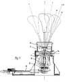
- the switching device is arranged in a dome-like housing 1, which can be placed on an opening of a transmission tunnel or the like.
- the selector lever 2 passes through a step-shaped shifting link 3 arranged on the top of the housing 1 and is movably mounted below this shifting link 3 about a transverse axis 4 in an intermediate part 5, which in turn is movable in the dome-like housing 1 about a pivot axis 6 arranged coaxially to the transverse axis is stored.
- a cross piece 7 made of a limited elastic material is provided, so that the selector lever 2 is gimbal-type in relation to the intermediate part 5 within predetermined limits.
- a rubber bearing can also be provided between the selector lever 2 and a cross piece 7, this rubber bearing possibly having recesses in order to achieve a softer design in an axial direction of the cross piece than in FIG the other direction.
- other spring elements in particular mechanical springs, can also be used, so that 5 restoring forces are built up for the automatic return to the central position when the selector lever is tilted together with the intermediate part.
- a Leg spring 13 presses the selector lever 2 in the switching positions P, R, N and D on one side against detents which are formed by the step-shaped design of the shifting gate 3.
- the intermediate part 5 is bow-shaped in the example, so that it is movably mounted in the housing 1 with the two legs running parallel to one another about the pivot axis 6.
- a slot 8 is provided which extends transversely to the longitudinal direction of the shifting gate 3 and through which a rod-shaped part of the selector lever 2 passes with a slight play in the longitudinal direction of the shifting gate 3.
- the lower end of the selector lever 2 engages in a cross slot 9 of a sliding block 10, which is firmly connected to the lower free leg ends of the intermediate part 5.
- the switching device is installed in a conventional manner so that the pivoting movement of the selector lever 2 for selecting the switching positions P, R, N and D takes place essentially in a plane extending in the longitudinal direction of the vehicle.
- the manual selection of a gear stage takes place through the pivoting locking of the selector lever in the shifting link 3 in the switching position D by a slight lateral pivoting movement of the selector lever 2 in the transverse direction into the secondary shifting position M and subsequent movement in the direction of the single shift gate.
- the intermediate part 5 When the switching positions P, R, N, D are selected, the intermediate part 5 is taken along by the selector lever 2 and pivoted about the pivot axis 6, these pivoting movements of the intermediate part in a conventional manner via linkages, cables 11 or the like, which are articulated with the intermediate part 5 are connected, can be transferred.
- the intermediate part 5 In the secondary shift position M assigned to manual shifting, the intermediate part 5 is locked by an electromagnet 14, so that when the selector lever 2 moves in a plane parallel to the longitudinal direction of the shift gate 3 the selector lever 2 is pivoted about the axis 6 with respect to the intermediate part 5, as shown in the drawing in FIG.
- This pivoting movement is made possible by the cross slot 9 in the sliding block 10 and serves to produce switching contacts for the manually triggered changeover to a next higher or next lower gear stage, as is known per se.
- a U-shaped bracket is arranged as an intermediate part 5 with the legs pointing upwards, so that the intermediate part 5 is open at the top.
- this intermediate part 5 which is open at the top, the lower end of the selector lever 2 is inserted with a likewise bow-shaped design, so that the universal-joint bearing of the selector lever 2 is accommodated with a cross piece 7 within the bow-shaped area at the lower end of the selector lever 2.
- the selector lever 2 has at least one driver 15 and 16 in the upper and in the lower region of the intermediate part 5, which engages in the vertical central position of the selector lever 2 in holding elements 17 and 18 on the intermediate piece in both selection directions effectively transversely.
- a pin 19 is arranged on the selector lever 2 or on its bow-shaped end, approximately at the level of the shifting gate in the housing, which engages in a recess 20 of the housing 1 in the switching secondary position M assigned to the manual, step-by-step switching, and thus the The fulcrum or the pivot axis of the shift lever in the shift auxiliary position M forms during step-by-step manual shifting.
- the drivers 15 and 16 are not in engagement with the holding elements 17 and 18, so that the selector lever 2 can be pivoted relative to the intermediate part 5 about the axis of the pin 19, by the manual circuit previously described for the exemplary embodiments in FIGS. 1 and 2 to enable.
- Such a design is shown in perspective in FIG.
- a continuous selector lever 2 which is mounted in the intermediate part 5 and the housing 1 to a limited extent in a universal joint about the axis 4, directly in the middle position above the joint axis 4 between holding elements 17 of the intermediate part 5 and below the joint axis between holding elements 18 of the intermediate part 5.
- the selector lever 2 is released by the holding elements 17 and 18, so that it can be pivoted about the X ′ axis for the manual step-by-step switching.
Landscapes
- Engineering & Computer Science (AREA)
- General Engineering & Computer Science (AREA)
- Mechanical Engineering (AREA)
- Arrangement Or Mounting Of Control Devices For Change-Speed Gearing (AREA)
- Control Of Transmission Device (AREA)
- Gear-Shifting Mechanisms (AREA)
Abstract
Description
Die Erfindung bezieht sich auf eine Schaltvorrichtung für ein automatisches Getriebe in einem Kraftfahrzeug nach dem Oberbegriff des Patentanspruches 1.The invention relates to a switching device for an automatic transmission in a motor vehicle according to the preamble of
Eine Schaltvorrichtung mit diesen Merkmalen ist aus der EP 0 624 741 -A1- bekannt. Hiernach wird der Schalthebel durch eine Feder ständig in Querrichtung belastet und in den Schaltstellungen P, R und N gegen Rastungen der Schaltkulisse gehalten. In der dem automatischen Schalten zugeordneten Schaltstellung D befindet sich der Schalthebel zwischen zwei elastischen Plattenelementen, die je mit einem elektrischen Schalter zusammenwirken, so daß durch eine Bewegung des Schalthebels in einer besonderen Gasse innerhalb der Schaltkulisse eine manuelle Schaltung der Gänge in der einen oder anderen Richtung möglich ist. Dabei bewegt sich der Schalthebel in einer seitlich neben der Hauptgasse liegenden Seitengasse, wie es an sich auch aus der DE 37 17 675 -C2- oder der DE 38 07 881 -C2- und anderen Druckschriften bekannt ist. Eine Schaltvorrichtung für ein automatisches Getriebe mit einer manuellen Gangwähleinrichtung mit nur einer einzigen, im wesentlichen geradlinigen Schaltgasse in der Schaltkulisse ergibt sich auf der DE 40 05 588 -C2-.A switching device with these features is known from
Der Erfindung liegt demgegenüber die Aufgabe zugrunde, eine Schaltvorrichtung der eingangs genannten Gattung in der Weise weiterzubilden, daß der automatische Schaltbereich und die manuelle Schaltung eindeutig voneinander getrennt sind.The invention is based on the object of developing a switching device of the type mentioned in such a way that the automatic switching range and the manual switching are clearly separated from each other.
Zur Lösung dieser Aufgabe wird erfindungsgemäß eine Ausbildung der eingangs genannten Schaltvorrichtung entsprechend dem Kennzeichen des Patentanspruches 1 vorgeschlagen.To achieve this object, an embodiment of the switching device mentioned at the outset is proposed according to the characterizing part of
Gegenüber bekannten Schaltvorrichtungen für automatische Getriebe mit manueller Gangwähleinrichtung erfolgt durch die Erfindungsmerkmale die Anwahl der dem automatischen Schalten zugeordneten Fahrstufen über das Zwischenteil durch Verschwenken des Wählhebels in der Schaltkulisse und die manuelle Anwahl eines Getriebeganges durch Verschwenkung des Wählhebels gegenüber dem Zwischenteil. Es werden somit für die Anwahlbewegungen der dem automatischen Schalten zugeordneten Schaltstellungen einerseits und für die Bewegungen zur manuellen Schaltung einer Gangstufe andererseits unterschiedliche Bauteile um unterschiedliche Schwenkachsen relativ zueinander bewegt. Vorzugsweise ist der Wählhebel in der dem automatischen Schalten zugeordneten Schaltstellung in der Schaltkulisse schwenkbeweglich arretiert und greift mit seinem unteren Ende in einen Gleitstein des Zwischenteils quer zur Richtung der Wählbewegung ein, um eine Schwenkbewegung des Wählhebels gegenüber dem Zwischenteil zu ermöglichen. Für das Zwischenteil empfiehlt sich eine bügelförmige Ausbildung, so daß der Bügel mit seinen Schenkeln um die Wählachse schwenkbar an einem festen Gehäuse gelagert werden kann, wobei der Bügel in seinem die Schenkel am oberen Ende miteinander verbindenden Steg einen Schlitz aufweist, der sich quer zur Wählbewegung erstreckt und von dem Wählhebel durchgriffen wird, der mit seinem unteren Ende unterhalb der Wählachse in einen sich quer zur Wählbewegung erstreckenden Schlitz eines mit dem Bügel verbundenen Gleitsteins eingreift. In der dem automatischen Schalten zugeordneten Schaltstellung greift der Wählhebel mit seinem unteren Ende in einen Querschlitz des Gleitsteines ein, so daß der um seine schwenkbewegliche Arretierung im Querschlitz des Bügelsteges schwenkbare Wählhebel mit seinem unteren Ende in dem Querschlitz gegenüber dem Bügel beweglich ist.Compared to known shifting devices for automatic transmissions with a manual gear selector, the inventive features enable the selection of the gears assigned to automatic shifting via the intermediate part by pivoting the selector lever in the shift gate and the manual selection of a transmission gear by pivoting the selector lever relative to the intermediate part. Thus, for the selection movements of the shift positions assigned to automatic shifting on the one hand and for the movements for manual shifting of a gear stage on the other hand, different components are moved relative to one another by different pivot axes. Preferably, the selector lever in the shift position associated with the automatic shifting is pivotally locked in the shifting gate and engages with its lower end in a sliding block of the intermediate part transversely to the direction of the selection movement in order to enable a pivoting movement of the selection lever relative to the intermediate part. For the intermediate part recommends a bow-shaped design, so that the bracket with its legs can be pivoted about the selection axis on a fixed housing, the bracket having a slot in its web connecting the legs at the upper end, which extends transversely to the selection movement and is penetrated by the selector lever, which engages with its lower end below the selection axis in a slot extending transversely to the selection movement of a sliding block connected to the bracket. In the switching position assigned to the automatic switching, the selector lever engages with its lower end in a transverse slot of the sliding block, so that the selector lever which can be pivoted about its pivotable locking in the transverse slot of the bracket web is movable with its lower end in the transverse slot relative to the bracket.
In der Zeichnung ist ein Ausführungsbeispiel der erfindungsgemäßen Ausbildung teilweise schematisch dargestellt. Es zeigen:
Figur 1- einen vertikalen Längsschnitt durch eine Schaltvorrichtung mit den Erfindungsmerkmalen,
Figur 2- einen gegenüber
Figur 1 um 90° versetzten Querschnitt, Figur 3- eine Draufsicht auf das Gehäuse der Schaltvorrichtung ohne Wählhebel,
Figur 4- einen Querschnitt
entsprechend Figur 2 durch ein abgeändertes Ausführungsbeispiel, Figur 5- eine Darstellung der Anordnung in
Figur 4, teilweise in Seitenansicht und teilweise im Schnitt durch das Gehäuse in Kippstellung des Wählhebels und Figur 6- eine perspektivische Darstellung einer vereinfachten Ausführungsform der Ausbildung nach den
Figuren 4 und 5.
- Figure 1
- a vertical longitudinal section through a switching device with the features of the invention,
- Figure 2
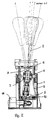
- a cross section offset by 90 ° compared to FIG. 1,
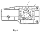
- Figure 3
- a plan view of the housing of the switching device without selector lever,
- Figure 4
- 3 shows a cross section corresponding to FIG. 2 through a modified exemplary embodiment,
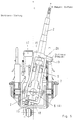
- Figure 5
- a representation of the arrangement in Figure 4, partly in side view and partly in section through the housing in the tilt position of the selector lever and
- Figure 6
- a perspective view of a simplified embodiment of the design according to Figures 4 and 5.
Die Schaltvorrichtung ist in einem domartigen Gehäuse 1 angeordnet, welches auf eine Öffnung eines Getriebetunnels oder dergleichen aufsetzbar ist. Der Wählhebel 2 durchsetzt eine an der Oberseite des Gehäuses 1 angeordnete, stufenförmige Schaltkulisse 3 und ist unterhalb dieser Schaltkulisse 3 um eine Querachse 4 in einem Zwischenteil 5 beweglich gelagert, welches seinerseits um eine koaxial zu der Querachse angeordnete Schwenkachse 6 beweglich in dem domartigen Gehäuse 1 gelagert ist. Zur Lagerung des Wählhebels 2 in dem Zwischenteil 5 ist ein Kreuzstück 7 aus einem begrenzt elastischen Werkstoff vorgesehen, so daß der Wählhebel 2 gegenüber dem Zwischenteil 5 in vorbestimmbaren Grenzen kardanisch beweglich ist. Um eine Kippbewegung des Wählhebels 2 gegenüber der Wählachse des Kreuzstückes 7 zu ermöglichen, kann auch eine Gummilagerung zwischen dem Wählhebel 2 und einem Kreuzstück 7 vorgesehen sein, wobei diese Gummilagerung eventuell Ausnehmungen aufweist, um in einer Achsrichtung des Kreuzstückes eine weichere Gestaltung zu erreichen als in der anderen Achsrichtung. Anstelle einer solchen elastischen Verbindung zwischen dem Wählhebel 2 und dem Kreuzstück 7 können auch andere Federelemente, insbesondere mechanische Federn, eingesetzt werden, so daß bei der Kippbewegung des Wählhebels zusammen mit dem Zwischenteil 5 Rückstellkräfte für die selbsttätige Rückkehr in die Mittellage aufgebaut werden. Eine Schenkelfeder 13 drückt den Wählhebel 2 in den Schaltstellungen P, R, N und D einseitig gegen Rastungen, die durch die stufenförmige Ausbildung der Schaltkulisse 3 gebildet sind. Das Zwischenteil 5 ist in dem Beispiel bügelförmig ausgebildet, so daß es mit den beiden parallel zueinander verlaufenden Schenkeln um die Schwenkachse 6 beweglich im Gehäuse 1 gelagert ist. In dem die Schenkel an der Oberseite miteinander verbindenden Steg ist ein sich quer zur Längsrichtung der Schaltkulisse 3 erstreckender Schlitz 8 vorgesehen, den ein stangenförmiger Teil des Wählhebels 2 mit einem geringen Spiel in Längsrichtung der Schaltkulisse 3 durchsetzt. Das untere Ende des Wählhebels 2 greift in einen Kreuzschlitz 9 eines Gleitsteines 10 ein, der mit den unteren freien Schenkelenden des Zwischenteiles 5 fest verbunden ist. Der Einbau der Schaltvorrichtung erfolgt in herkömmlicher Weise so, daß die Schwenkbewegung des Wählhebels 2 zur Anwahl der Schaltstellungen P, R, N und D im wesentlichen in einer sich in Längsrichtung des Fahrzeuges erstreckenden Ebene erfolgt. Die manuelle Anwahl einer Gangstufe erfolgt durch die schwenkbewegliche Arretierung des Wählhebels in der Schaltkulisse 3 in der Schaltstellung D durch eine leichte seitliche Schwenkbewegung des Wählhebels 2 in Querrichtung bis in die Nebenschaltstellung M und anschließender Bewegung in Richtung der einzigen Schaltgasse. Bei der Anwahl der Schaltstellungen P, R, N, D wird das Zwischenteil 5 von dem Wählhebel 2 mitgenommen und um die Schwenkachse 6 verschwenkt, wobei diese Schwenkbewegungen des Zwischenteils in herkömmlicher Weise über Gestänge, Seilzüge 11 oder dergleichen, die gelenkig mit dem Zwischenteil 5 verbunden sind, übertragen werden können. In der dem manuellen Schalten zugeordneten Nebenschaltstellung M wird das Zwischenteil 5 durch einen Elektromagneten 14 arretiert, so daß bei einer Bewegung des Wählhebels 2 in einer Ebene parallel zur Längsrichtung der Schaltkulisse 3 eine Verschwenkung des Wählhebels 2 um die Achse 6 gegenüber dem Zwischenteil 5 erfolgt, wie es in der Figur 2 zeichnerisch dargestellt ist. Diese Schwenkbewegung wird durch den Kreuzschlitz 9 in dem Gleitstein 10 ermöglicht und dient zur Herstellung von Schaltkontakten für die manuell ausgelöste Umschaltung in eine nächsthöhere oder nächstniedere Gangstufe, wie es an sich bekannt ist.The switching device is arranged in a dome-
In der Figur 1 ist außerdem dargestellt, daß für die Schaltstellungen P, R. N und D mit der Schaltnebenstellung M in einem Bauteil 12 zusätzliche Rastungen mit einer Federbelastung angeordnet sein können.In Figure 1 it is also shown that for the switching positions P, R. N and D with the switching
Bei den Ausführungsbeispielen in den Figuren 4, 5 und 6 ist ein U-förmiger Bügel als Zwischenteil 5 mit den Schenkeln nach oben gerichtet angeordnet, so daß das Zwischenteil 5 nach oben offen ist. In dieses nach oben offene Zwischenteil 5 ist das untere Ende des Wählhebels 2 mit einer ebenfalls bügelförmigen Ausbildung eingesetzt, so daß die universalgelenkige Lagerung des Wählhebels 2 mit einem Kreuzstück 7 innerhalb des bügelförmigen Bereiches am unteren Ende des Wählhebels 2 untergebracht ist. Bei dieser Anordnung weist der Wählhebel 2 im oberen und im unteren Bereich des Zwischenteiles 5 wenigstens je einen Mitnehmer 15 und 16 auf, der in der senkrechten Mittellage des Wählhebels 2 in Halteelemente 17 und 18 am Zwischenstück in beiden Wählrichtungen wirksam querbeweglich eingreift. Außerdem ist an dem Wählhebel 2 bzw. an seinem bügelförmig ausgebildeten Ende, etwa in Höhe der Schaltkulisse in dem Gehäuse,ein Zapfen 19 angeordnet, der in der dem manuellen, schrittweisen Schalten zugeordneten Schaltnebenstellung M in eine Ausnehmung 20 des Gehäuses 1 eingreift und somit den Drehpunkt bzw. die Schwenkachse des Schalthebels in der Schaltnebenstellung M beim schrittweisen manuellen Schalten bildet. In der diesem manuellen Schalten zugeordneten Kipplage befinden sich die Mitnehmer 15 und 16 nicht im Eingriff mit den Halteelementen 17 und 18, so daß der Wählhebel 2 gegenüber dem Zwischenteil 5 um die Achse des Zapfens 19 schwenkbar ist, um die zuvor zu den Ausführungsbeispielen der Figuren 1 und 2 beschriebene manuelle Schaltung zu ermöglichen. Vereinfacht ist eine solche Ausbildung in der Figur 6 perspektivisch dargestellt. In diesem Falle greift ein durchgehender Wählhebel 2, welcher um die Achse 4 begrenzt universalgelenkig in dem Zwischenteil 5 und dem Gehäuse 1 gelagert ist, in der Mittellage oberhalb der Gelenkachse 4 unmittelbar zwischen Halteelemente 17 des Zwischenteiles 5 und unterhalb der Gelenkachse zwischen Halteelemente 18 des Zwischenteiles 5. Bei einer Kippbewegung wird der Wählhebel 2 von den Halteelementen 17 und 18 freigegeben, so daß er für die manuelle schrittweise Schaltung um die X'-Achse schwenkbar ist.In the exemplary embodiments in FIGS. 4, 5 and 6, a U-shaped bracket is arranged as an
- 11
- Gehäusecasing
- 22nd
- WählhebelSelector lever
- 33rd
- SchaltkulisseShifting gate
- 44th
- QuerachseTransverse axis
- 55
- ZwischenteilIntermediate part
- 66
- SchwenkachseSwivel axis
- 77
- KreuzstückCross piece
- 88th
- Schlitzslot
- 99
- KreuzschlitzCross recess
- 1010th
- GleitsteinSliding block
- 1111
- SeilzugCable
- 1212th
- BauteilComponent
- 1313
- SchenkelfederLeg spring
- 1414
- ElektromagnetElectromagnet
- 1515
- MitnehmerCarrier
- 1616
- MitnehmerCarrier
- 1717th
- HalteelementHolding element
- 1818th
- HalteelementHolding element
- 1919th
- ZapfenCones
- 2020th
- AusnehmungRecess
- P, R, N, D und MP, R, N, D and M
- - Schaltstellungen- switch positions
Claims (8)
Applications Claiming Priority (2)
| Application Number | Priority Date | Filing Date | Title |
|---|---|---|---|
| DE19526059A DE19526059C2 (en) | 1995-07-17 | 1995-07-17 | Switching device for an automatic transmission of a motor vehicle |
| DE19526059 | 1995-07-17 |
Publications (3)
| Publication Number | Publication Date |
|---|---|
| EP0754884A2 true EP0754884A2 (en) | 1997-01-22 |
| EP0754884A3 EP0754884A3 (en) | 1997-07-23 |
| EP0754884B1 EP0754884B1 (en) | 1999-09-15 |
Family
ID=7767068
Family Applications (1)
| Application Number | Title | Priority Date | Filing Date |
|---|---|---|---|
| EP95117755A Expired - Lifetime EP0754884B1 (en) | 1995-07-17 | 1995-11-10 | Shift control unit for an automatic transmission in an automotive vehicle |
Country Status (5)
| Country | Link |
|---|---|
| US (1) | US5689996A (en) |
| EP (1) | EP0754884B1 (en) |
| JP (1) | JP3059387B2 (en) |
| DE (4) | DE19549437C2 (en) |
| ES (1) | ES2137435T3 (en) |
Cited By (6)
| Publication number | Priority date | Publication date | Assignee | Title |
|---|---|---|---|---|
| EP0881413A1 (en) * | 1997-05-30 | 1998-12-02 | Automobiles Peugeot | Shift actuator for an automatic mult-stage gearbox |
| EP0899478A1 (en) * | 1997-08-29 | 1999-03-03 | Fuji Kiko Company Limited | Shift lever apparatus for automatic transmission |
| EP0825364A3 (en) * | 1996-08-22 | 1999-04-07 | Bayerische Motoren Werke Aktiengesellschaft, Patentabteilung AJ-3 | Shift selector for automatic vehicle transmission |
| EP0936383A1 (en) * | 1998-02-10 | 1999-08-18 | Mazda Motor Corporation | Shifting arrangement for automatic transmission of motor vehicle |
| EP1365177A3 (en) * | 1998-11-23 | 2004-07-14 | ZF Lemförder Metallwaren AG | Selector device for the gearbox of a motor vehicle |
| CN104712753A (en) * | 2015-02-04 | 2015-06-17 | 十堰耐博汽车科技有限公司 | Gear shifter assembly of electric vehicle |
Families Citing this family (56)
| Publication number | Priority date | Publication date | Assignee | Title |
|---|---|---|---|---|
| EP0770799B1 (en) * | 1995-10-24 | 2000-12-27 | Fuji Kiko Co., Ltd. | Shift lever device for automatic transmission |
| DE19600526C2 (en) * | 1996-01-10 | 1998-02-19 | Lemfoerder Metallwaren Ag | Switching device for an automatic transmission of a motor vehicle |
| JP2916889B2 (en) * | 1996-01-11 | 1999-07-05 | ナイルス部品株式会社 | Speed change device for vehicle |
| EP0794362B1 (en) * | 1996-03-08 | 2001-09-19 | ZF Lemförder Metallwaren AG | Gear selector for a transmission |
| IT1286287B1 (en) * | 1996-03-29 | 1998-07-08 | Roltra Morse Spa | GUIDE FOR A SELECTION LEVER |
| IT1286289B1 (en) * | 1996-03-29 | 1998-07-08 | Roltra Morse Spa | LOCKING DEVICE FOR A SELECTION LEVER |
| DE19620515C2 (en) | 1996-05-22 | 1998-04-30 | Lemfoerder Metallwaren Ag | Switching device for an automatic transmission of a motor vehicle |
| DE19637254C2 (en) * | 1996-09-13 | 1998-07-30 | Lemfoerder Metallwaren Ag | Selector device for an automatic transmission of motor vehicles |
| DE19650154C2 (en) | 1996-12-04 | 1999-06-10 | Lemfoerder Metallwaren Ag | Switching device for a transmission of a motor vehicle with a printed circuit board equipped with sensors, light-emitting diodes, processes and other electronic components and method for producing a curved printed circuit board for use in such a switching device |
| US5799539A (en) * | 1997-01-21 | 1998-09-01 | Ford Global Technologies, Inc. | Manually shifted automatic transmission lever |
| DE19747333C1 (en) * | 1997-10-27 | 1999-04-22 | Ford Global Tech Inc | Selector lever arrangement for auxiliary gearboxes of motor vehicles |
| DE19756034C2 (en) * | 1997-12-17 | 2003-11-06 | Zf Lemfoerder Metallwaren Ag | Selector device for a vehicle transmission |
| DE19905627B4 (en) * | 1998-02-16 | 2008-09-25 | Luk Gs Verwaltungs Kg | Transmission for a motor vehicle with a selector |
| DE19811972C2 (en) * | 1998-03-19 | 2000-01-13 | Lemfoerder Metallwaren Ag | Selector device for an automatic transmission of a motor vehicle |
| SE512418C2 (en) * | 1998-06-29 | 2000-03-13 | Kongsberg Automotive Ab | Operating device |
| DE19832086B4 (en) * | 1998-07-16 | 2008-05-29 | Fico Triad S.A., Rubi | lever unit |
| US6295886B1 (en) * | 1998-10-08 | 2001-10-02 | Dura Global Technologies | Vehicle shift mechanism for an automatic transmission |
| DE19850374B4 (en) * | 1998-11-02 | 2007-05-10 | Bayerische Motoren Werke Ag | Motor vehicle with a drive motor and an automatically connected transmission with a selection device |
| DE19851211B4 (en) * | 1998-11-06 | 2007-04-19 | ZF Lemförder Metallwaren AG | Slot cover for the selector housing of the circuit of a vehicle transmission |
| DE19937698C2 (en) | 1999-08-10 | 2001-09-13 | Zf Lemfoerder Metallwaren Ag | Switching device of an automatic motor vehicle transmission |
| US6230579B1 (en) | 1999-11-17 | 2001-05-15 | Teleflex Incorporated | Multi-mode shifter assembly joint |
| DE10022433B4 (en) * | 2000-05-09 | 2006-07-13 | Daimlerchrysler Ag | lever device |
| US6631653B2 (en) * | 2000-12-06 | 2003-10-14 | Caterpillar Inc. | System for definable single lever control shift pattern joint |
| DE10102843C2 (en) * | 2001-01-22 | 2003-07-17 | Zf Lemfoerder Metallwaren Ag | Switching device for switching between different operating states of a motor vehicle transmission |
| JP4668439B2 (en) * | 2001-03-12 | 2011-04-13 | 株式会社東海理化電機製作所 | Shift lever device |
| US6786108B2 (en) * | 2002-08-12 | 2004-09-07 | Taiwan Power Industrial Co., Ltd. | Gear lever clutching structure for prevention of gear slip |
| KR100494788B1 (en) * | 2002-10-24 | 2005-06-13 | 현대자동차주식회사 | shift lock device for a shift lever of an auto transmission |
| US20040168537A1 (en) * | 2003-02-28 | 2004-09-02 | Teleflex Incorporated | Shifter assembly for an automatic transmission |
| USPP15990P3 (en) * | 2003-04-23 | 2005-09-20 | J. C. Bakker & Sons Limited | Lilac plant named ‘Golden Eclipse’ |
| US7393304B2 (en) | 2003-05-15 | 2008-07-01 | Grand Haven Stamped Products | Shifter with gear position indicator |
| US7221248B2 (en) * | 2003-05-15 | 2007-05-22 | Grand Haven Stamped Products | Solenoid with noise reduction |
| DE10347347B4 (en) * | 2003-10-11 | 2006-02-16 | Daimlerchrysler Ag | Selector lever and method for mounting a selector lever |
| DE10353240A1 (en) * | 2003-11-13 | 2005-06-16 | Zf Friedrichshafen Ag | switching device |
| DE102004006150B3 (en) * | 2004-02-07 | 2005-09-15 | Teleflex Automotive Germany Gmbh | Control device for electronic step control for automatic transmission |
| DE102004033672B4 (en) * | 2004-07-09 | 2006-09-21 | Zf Friedrichshafen Ag | Switching device for an automatic transmission |
| US7328782B2 (en) | 2004-07-26 | 2008-02-12 | Grand Haven Stamped Products Company, A Division Of Jsj Corporation | Vehicle shifter with powered pawl having neutral lock |
| US7568404B2 (en) | 2004-07-26 | 2009-08-04 | Ghsp, A Division Of Jsj Corporation | Shifter having neutral lock |
| DE102004056778A1 (en) * | 2004-11-24 | 2006-06-01 | Volkswagen Ag | Shift console of a motor vehicle transmission |
| DE102006021078B3 (en) * | 2006-05-05 | 2007-08-23 | Cherry Gmbh | Electronic selecting lever module for an automatic gear box of a motor vehicle comprises a mechanism with an interacting rotor, a slide and a sleeve |
| FR2909741B1 (en) * | 2006-12-12 | 2009-11-13 | Teleflex Automotive France Sas | DEVICE FOR CONTROLLING A GEARBOX. |
| JP4637086B2 (en) * | 2006-12-26 | 2011-02-23 | 富士機工株式会社 | Shift lever device for automatic transmission |
| DE102007038495A1 (en) * | 2007-08-14 | 2009-02-19 | Zf Friedrichshafen Ag | Actuation device with shift carriage lock |
| DE102008028619A1 (en) | 2008-06-18 | 2009-12-24 | Ecs Engineered Control Systems Ag | Switching device for a transmission |
| US8371188B2 (en) * | 2008-10-02 | 2013-02-12 | Kongsberg Driveline Systems I, Inc. | Transmission control assembly having a locking mechanism |
| JP5225937B2 (en) * | 2009-06-08 | 2013-07-03 | デルタ工業株式会社 | Automatic transmission shift device |
| DE102011053177A1 (en) * | 2011-08-31 | 2013-02-28 | ECS Engineered Control System AG | switching device |
| EP2581629B1 (en) | 2012-03-22 | 2014-06-04 | Kongsberg Automotive AB | Shifter assembly with reduced lash |
| DE102012104098B4 (en) | 2012-05-10 | 2015-08-27 | Elobau Gmbh & Co. Kg | Lockable joystick |
| KR101345155B1 (en) * | 2013-02-01 | 2013-12-26 | 현대자동차주식회사 | Structure of lever of vehicle transmission |
| CN103591276B (en) * | 2013-11-29 | 2016-09-28 | 安徽江淮汽车股份有限公司 | A kind of restorable selects selector device |
| DE102014201477A1 (en) * | 2014-01-28 | 2015-07-30 | Zf Friedrichshafen Ag | Translation device and method for translating an operating angle of a selector lever for a shift operation for a vehicle transmission |
| WO2015139740A1 (en) * | 2014-03-18 | 2015-09-24 | Kongsberg Automotive Ab | Gear shifter including a position sensor assembly |
| DE102014107077B3 (en) * | 2014-05-20 | 2015-08-13 | Ecs Engineered Control Systems Ag | switching device |
| DE102015102317A1 (en) | 2015-02-18 | 2016-08-18 | Elobau Gmbh & Co. Kg | joystick |
| DE102015102607A1 (en) | 2015-02-24 | 2016-08-25 | Küster Holding GmbH | Switching device for an automatic transmission of a motor vehicle |
| CN107923519B (en) | 2015-09-03 | 2019-11-05 | 康斯博格汽车股份公司 | Shift assembly including position sensor assembly |
Citations (4)
| Publication number | Priority date | Publication date | Assignee | Title |
|---|---|---|---|---|
| DE3807881C2 (en) | 1988-03-10 | 1992-08-27 | Dr.Ing.H.C. F. Porsche Ag, 7000 Stuttgart, De | |
| DE3717675C2 (en) | 1987-05-26 | 1994-09-29 | Bayerische Motoren Werke Ag | Switching device for a motor vehicle with an automatic transmission |
| EP0624741A1 (en) | 1993-05-11 | 1994-11-17 | Automobiles Peugeot | Gear shift device for an automatic automotiv gearbox |
| DE4005588C2 (en) | 1990-02-22 | 1995-03-23 | Porsche Ag | Switching device for an automatic transmission |
Family Cites Families (12)
| Publication number | Priority date | Publication date | Assignee | Title |
|---|---|---|---|---|
| DE3927250A1 (en) * | 1989-08-18 | 1991-02-21 | Porsche Ag | SWITCHING DEVICE |
| DE3927248C1 (en) * | 1989-08-18 | 1991-02-07 | Dr.Ing.H.C. F. Porsche Ag, 7000 Stuttgart, De | |
| US5044220A (en) * | 1988-03-10 | 1991-09-03 | Dr. Ing. H.C.F. Porsche Ag | Shifting arrangement for an automatic transmission of a motor vehicle |
| TW248544B (en) * | 1991-04-03 | 1995-06-01 | Torrington Co | |
| JPH04123821U (en) * | 1991-04-25 | 1992-11-10 | 日産デイーゼル工業株式会社 | Shift change operation lever device for automatic transmission vehicles |
| DE4217773A1 (en) * | 1992-05-29 | 1993-12-02 | Audi Ag | Vehicle automatic gearbox selector - has conventional arrangement of manual gears and electronic control unit for gear changing in DRIVE position |
| JP3187978B2 (en) * | 1992-09-10 | 2001-07-16 | マツダ株式会社 | Operating device for automatic transmission |
| JPH06280993A (en) * | 1993-03-26 | 1994-10-07 | Matsushita Electric Works Ltd | Position signal generating device |
| JP3428061B2 (en) * | 1993-03-31 | 2003-07-22 | マツダ株式会社 | Shifting device for automatic transmission |
| FR2703958B1 (en) * | 1993-04-13 | 1995-07-13 | Jaeger | CONTROL ASSEMBLY FOR A MECHANICAL GEARBOX AND CONTROL SYSTEM INCORPORATING THE SAME. |
| US5509322A (en) * | 1994-06-02 | 1996-04-23 | Chrysler Corporation | Shift control mechanism to manually shift an automatic transmission |
| DE4426207C5 (en) * | 1994-07-23 | 2008-08-28 | Bayerische Motoren Werke Aktiengesellschaft | Selection device for an automatic transmission of a motor vehicle |
-
1995
- 1995-07-17 DE DE19549437A patent/DE19549437C2/en not_active Expired - Fee Related
- 1995-07-17 DE DE19526059A patent/DE19526059C2/en not_active Expired - Fee Related
- 1995-11-10 DE DE59506847T patent/DE59506847D1/en not_active Expired - Lifetime
- 1995-11-10 EP EP95117755A patent/EP0754884B1/en not_active Expired - Lifetime
- 1995-11-10 ES ES95117755T patent/ES2137435T3/en not_active Expired - Lifetime
-
1996
- 1996-02-05 US US08/597,041 patent/US5689996A/en not_active Expired - Lifetime
- 1996-03-08 DE DE19608981A patent/DE19608981B4/en not_active Expired - Fee Related
- 1996-07-11 JP JP8181966A patent/JP3059387B2/en not_active Expired - Fee Related
Patent Citations (4)
| Publication number | Priority date | Publication date | Assignee | Title |
|---|---|---|---|---|
| DE3717675C2 (en) | 1987-05-26 | 1994-09-29 | Bayerische Motoren Werke Ag | Switching device for a motor vehicle with an automatic transmission |
| DE3807881C2 (en) | 1988-03-10 | 1992-08-27 | Dr.Ing.H.C. F. Porsche Ag, 7000 Stuttgart, De | |
| DE4005588C2 (en) | 1990-02-22 | 1995-03-23 | Porsche Ag | Switching device for an automatic transmission |
| EP0624741A1 (en) | 1993-05-11 | 1994-11-17 | Automobiles Peugeot | Gear shift device for an automatic automotiv gearbox |
Cited By (10)
| Publication number | Priority date | Publication date | Assignee | Title |
|---|---|---|---|---|
| EP0825364A3 (en) * | 1996-08-22 | 1999-04-07 | Bayerische Motoren Werke Aktiengesellschaft, Patentabteilung AJ-3 | Shift selector for automatic vehicle transmission |
| EP0881413A1 (en) * | 1997-05-30 | 1998-12-02 | Automobiles Peugeot | Shift actuator for an automatic mult-stage gearbox |
| FR2764025A1 (en) * | 1997-05-30 | 1998-12-04 | Peugeot | CONTROL DEVICE FOR AN AUTOMATIC STAGE GEARBOX |
| EP0899478A1 (en) * | 1997-08-29 | 1999-03-03 | Fuji Kiko Company Limited | Shift lever apparatus for automatic transmission |
| US6148686A (en) * | 1997-08-29 | 2000-11-21 | Fuji Kiko Co., Ltd. | Shift lever apparatus for automatic transmission |
| EP0936383A1 (en) * | 1998-02-10 | 1999-08-18 | Mazda Motor Corporation | Shifting arrangement for automatic transmission of motor vehicle |
| US6192770B1 (en) | 1998-02-10 | 2001-02-27 | Mazda Motor Corporation | Shift select lever device for manually-shiftable automatic transmission |
| EP1365177A3 (en) * | 1998-11-23 | 2004-07-14 | ZF Lemförder Metallwaren AG | Selector device for the gearbox of a motor vehicle |
| CN104712753A (en) * | 2015-02-04 | 2015-06-17 | 十堰耐博汽车科技有限公司 | Gear shifter assembly of electric vehicle |
| CN104712753B (en) * | 2015-02-04 | 2018-04-13 | 十堰耐博汽车科技有限公司 | Electric car gear shifter assembly |
Also Published As
| Publication number | Publication date |
|---|---|
| EP0754884B1 (en) | 1999-09-15 |
| JPH0932911A (en) | 1997-02-07 |
| US5689996A (en) | 1997-11-25 |
| DE59506847D1 (en) | 1999-10-21 |
| DE19526059C2 (en) | 1999-05-27 |
| EP0754884A3 (en) | 1997-07-23 |
| DE19608981B4 (en) | 2012-03-08 |
| DE19608981A1 (en) | 1997-09-11 |
| JP3059387B2 (en) | 2000-07-04 |
| ES2137435T3 (en) | 1999-12-16 |
| DE19549437A1 (en) | 1997-03-20 |
| DE19526059A1 (en) | 1997-01-23 |
| DE19549437C2 (en) | 1999-06-10 |
Similar Documents
| Publication | Publication Date | Title |
|---|---|---|
| EP0754884B1 (en) | Shift control unit for an automatic transmission in an automotive vehicle | |
| EP0693391B1 (en) | Gear selection apparatus for an automatic transmission of a motor vehicle | |
| DE2919062A1 (en) | SWITCHING DEVICE | |
| DE19853934B4 (en) | Switching device of a motor vehicle transmission | |
| EP0837266B1 (en) | Selecting device for an automatic transmission of a vehicle | |
| EP0809046B1 (en) | Gear-shifting device for an automatic transmission of a motor vehicle | |
| DE102005043288A1 (en) | Electrical switching device for a motor vehicle | |
| EP0231924A2 (en) | Electrical switch, particularly steering column switch for vehicle | |
| DE102007007667A1 (en) | Electrical switching device for a motor vehicle | |
| DE19913835C2 (en) | Switching device for motor vehicles | |
| DE10027484C1 (en) | Combined tipping and sliding switch for automobile sunroof operating device has sliding and pivoted switch operating element with 2 parallel switch pieces acting on respective operating bridges | |
| DE10202577B4 (en) | switching device | |
| EP1531290A2 (en) | Gear selector device | |
| EP1267240A1 (en) | Gear change device for a manual transmission of a motor vehicle | |
| DE19526951C2 (en) | Switching device for an automatic transmission | |
| DE19737366A1 (en) | Switchgear for automatic gear in motor vehicle | |
| DE102005057814B4 (en) | Multi-function switch for a motor vehicle sliding-lifting roof | |
| EP1333196B1 (en) | Bearing assembly for pivotable gear shift lever | |
| DE102024138996B3 (en) | Electrical switching device with spring-loaded pressure piece | |
| EP1899998B1 (en) | Switch for a motor vehicle | |
| DE19900412A1 (en) | Selection arrangement for motor vehicle automatic gearbox has gear change axle mounted to move along guide, perpendicularly to itself and elastically about central position | |
| DE10111375B4 (en) | Selection device for an automatic transmission | |
| DE19600525C1 (en) | Switchgear for vehicle's automatic gear | |
| DE2509701A1 (en) | Motor vehicle steering column switch - has switching slide displaceable in guideway against force of two springs | |
| EP1321954A1 (en) | Switch unit and control lever with integrated switch unit |
Legal Events
| Date | Code | Title | Description |
|---|---|---|---|
| PUAI | Public reference made under article 153(3) epc to a published international application that has entered the european phase |
Free format text: ORIGINAL CODE: 0009012 |
|
| AK | Designated contracting states |
Kind code of ref document: A2 Designated state(s): DE ES FR GB IT NL SE |
|
| PUAL | Search report despatched |
Free format text: ORIGINAL CODE: 0009013 |
|
| AK | Designated contracting states |
Kind code of ref document: A3 Designated state(s): DE ES FR GB IT NL SE |
|
| 17P | Request for examination filed |
Effective date: 19971105 |
|
| GRAG | Despatch of communication of intention to grant |
Free format text: ORIGINAL CODE: EPIDOS AGRA |
|
| GRAG | Despatch of communication of intention to grant |
Free format text: ORIGINAL CODE: EPIDOS AGRA |
|
| GRAH | Despatch of communication of intention to grant a patent |
Free format text: ORIGINAL CODE: EPIDOS IGRA |
|
| GRAH | Despatch of communication of intention to grant a patent |
Free format text: ORIGINAL CODE: EPIDOS IGRA |
|
| 17Q | First examination report despatched |
Effective date: 19990312 |
|
| RAP1 | Party data changed (applicant data changed or rights of an application transferred) |
Owner name: LEMFOERDER METALLWAREN AG |
|
| GRAA | (expected) grant |
Free format text: ORIGINAL CODE: 0009210 |
|
| AK | Designated contracting states |
Kind code of ref document: B1 Designated state(s): DE ES FR GB IT NL SE |
|
| GBT | Gb: translation of ep patent filed (gb section 77(6)(a)/1977) |
Effective date: 19990917 |
|
| REF | Corresponds to: |
Ref document number: 59506847 Country of ref document: DE Date of ref document: 19991021 |
|
| ET | Fr: translation filed | ||
| ITF | It: translation for a ep patent filed | ||
| REG | Reference to a national code |
Ref country code: ES Ref legal event code: FG2A Ref document number: 2137435 Country of ref document: ES Kind code of ref document: T3 |
|
| PLBE | No opposition filed within time limit |
Free format text: ORIGINAL CODE: 0009261 |
|
| STAA | Information on the status of an ep patent application or granted ep patent |
Free format text: STATUS: NO OPPOSITION FILED WITHIN TIME LIMIT |
|
| 26N | No opposition filed | ||
| REG | Reference to a national code |
Ref country code: GB Ref legal event code: IF02 |
|
| PGFP | Annual fee paid to national office [announced via postgrant information from national office to epo] |
Ref country code: NL Payment date: 20081103 Year of fee payment: 14 |
|
| PGFP | Annual fee paid to national office [announced via postgrant information from national office to epo] |
Ref country code: SE Payment date: 20091106 Year of fee payment: 15 Ref country code: ES Payment date: 20091201 Year of fee payment: 15 Ref country code: DE Payment date: 20091105 Year of fee payment: 15 |
|
| PGFP | Annual fee paid to national office [announced via postgrant information from national office to epo] |
Ref country code: IT Payment date: 20091114 Year of fee payment: 15 Ref country code: GB Payment date: 20091104 Year of fee payment: 15 Ref country code: FR Payment date: 20091123 Year of fee payment: 15 |
|
| REG | Reference to a national code |
Ref country code: NL Ref legal event code: V1 Effective date: 20100601 |
|
| PG25 | Lapsed in a contracting state [announced via postgrant information from national office to epo] |
Ref country code: NL Free format text: LAPSE BECAUSE OF NON-PAYMENT OF DUE FEES Effective date: 20100601 |
|
| REG | Reference to a national code |
Ref country code: SE Ref legal event code: EUG |
|
| GBPC | Gb: european patent ceased through non-payment of renewal fee |
Effective date: 20101110 |
|
| REG | Reference to a national code |
Ref country code: DE Ref legal event code: R119 Ref document number: 59506847 Country of ref document: DE Effective date: 20110601 Ref country code: DE Ref legal event code: R119 Ref document number: 59506847 Country of ref document: DE Effective date: 20110531 |
|
| REG | Reference to a national code |
Ref country code: FR Ref legal event code: ST Effective date: 20110801 |
|
| PG25 | Lapsed in a contracting state [announced via postgrant information from national office to epo] |
Ref country code: SE Free format text: LAPSE BECAUSE OF NON-PAYMENT OF DUE FEES Effective date: 20101111 Ref country code: DE Free format text: LAPSE BECAUSE OF NON-PAYMENT OF DUE FEES Effective date: 20110531 |
|
| PG25 | Lapsed in a contracting state [announced via postgrant information from national office to epo] |
Ref country code: FR Free format text: LAPSE BECAUSE OF NON-PAYMENT OF DUE FEES Effective date: 20101130 |
|
| PG25 | Lapsed in a contracting state [announced via postgrant information from national office to epo] |
Ref country code: GB Free format text: LAPSE BECAUSE OF NON-PAYMENT OF DUE FEES Effective date: 20101110 |
|
| PG25 | Lapsed in a contracting state [announced via postgrant information from national office to epo] |
Ref country code: IT Free format text: LAPSE BECAUSE OF NON-PAYMENT OF DUE FEES Effective date: 20101110 |
|
| REG | Reference to a national code |
Ref country code: ES Ref legal event code: FD2A Effective date: 20120110 |
|
| PG25 | Lapsed in a contracting state [announced via postgrant information from national office to epo] |
Ref country code: ES Free format text: LAPSE BECAUSE OF NON-PAYMENT OF DUE FEES Effective date: 20101111 |