EP0754584A2 - Method to unlock a window pane with an inflatable pressure hose - Google Patents
Method to unlock a window pane with an inflatable pressure hose Download PDFInfo
- Publication number
- EP0754584A2 EP0754584A2 EP96111076A EP96111076A EP0754584A2 EP 0754584 A2 EP0754584 A2 EP 0754584A2 EP 96111076 A EP96111076 A EP 96111076A EP 96111076 A EP96111076 A EP 96111076A EP 0754584 A2 EP0754584 A2 EP 0754584A2
- Authority
- EP
- European Patent Office
- Prior art keywords
- window pane
- pressure hose
- frame element
- window
- inflated
- Prior art date
- Legal status (The legal status is an assumption and is not a legal conclusion. Google has not performed a legal analysis and makes no representation as to the accuracy of the status listed.)
- Withdrawn
Links
Images
Classifications
-
- B—PERFORMING OPERATIONS; TRANSPORTING
- B61—RAILWAYS
- B61D—BODY DETAILS OR KINDS OF RAILWAY VEHICLES
- B61D25/00—Window arrangements peculiar to rail vehicles
-
- A—HUMAN NECESSITIES
- A62—LIFE-SAVING; FIRE-FIGHTING
- A62B—DEVICES, APPARATUS OR METHODS FOR LIFE-SAVING
- A62B3/00—Devices or single parts for facilitating escape from buildings or the like, e.g. protection shields, protection screens; Portable devices for preventing smoke penetrating into distinct parts of buildings
-
- B—PERFORMING OPERATIONS; TRANSPORTING
- B60—VEHICLES IN GENERAL
- B60J—WINDOWS, WINDSCREENS, NON-FIXED ROOFS, DOORS, OR SIMILAR DEVICES FOR VEHICLES; REMOVABLE EXTERNAL PROTECTIVE COVERINGS SPECIALLY ADAPTED FOR VEHICLES
- B60J1/00—Windows; Windscreens; Accessories therefor
- B60J1/08—Windows; Windscreens; Accessories therefor arranged at vehicle sides
- B60J1/10—Windows; Windscreens; Accessories therefor arranged at vehicle sides fixedly mounted
-
- B—PERFORMING OPERATIONS; TRANSPORTING
- B60—VEHICLES IN GENERAL
- B60J—WINDOWS, WINDSCREENS, NON-FIXED ROOFS, DOORS, OR SIMILAR DEVICES FOR VEHICLES; REMOVABLE EXTERNAL PROTECTIVE COVERINGS SPECIALLY ADAPTED FOR VEHICLES
- B60J10/00—Sealing arrangements
- B60J10/20—Sealing arrangements characterised by the shape
- B60J10/24—Sealing arrangements characterised by the shape having tubular parts
- B60J10/244—Sealing arrangements characterised by the shape having tubular parts inflatable or deflatable
-
- B—PERFORMING OPERATIONS; TRANSPORTING
- B60—VEHICLES IN GENERAL
- B60J—WINDOWS, WINDSCREENS, NON-FIXED ROOFS, DOORS, OR SIMILAR DEVICES FOR VEHICLES; REMOVABLE EXTERNAL PROTECTIVE COVERINGS SPECIALLY ADAPTED FOR VEHICLES
- B60J10/00—Sealing arrangements
- B60J10/70—Sealing arrangements specially adapted for windows or windscreens
-
- B—PERFORMING OPERATIONS; TRANSPORTING
- B29—WORKING OF PLASTICS; WORKING OF SUBSTANCES IN A PLASTIC STATE IN GENERAL
- B29C—SHAPING OR JOINING OF PLASTICS; SHAPING OF MATERIAL IN A PLASTIC STATE, NOT OTHERWISE PROVIDED FOR; AFTER-TREATMENT OF THE SHAPED PRODUCTS, e.g. REPAIRING
- B29C65/00—Joining or sealing of preformed parts, e.g. welding of plastics materials; Apparatus therefor
- B29C65/76—Making non-permanent or releasable joints
Definitions
- the invention relates to a method for unlocking a window pane with an inflatable pressure hose according to the preamble of claim 1.
- an unlocking device for a window pane which is connected to a frame element via a sealing profile, the window pane being fastened to the frame element via a fastening element.
- a gas-fillable, deformable hose is arranged in this or on the fastening element, which in the inflated state tears open the fastening of the window pane so that the window pane falls out of the frame element.
- the invention has for its object to provide a method for unlocking a window pane according to the preamble of claim 1, which ensures almost 100% with simple means that in an emergency the window pane falls out of the frame.
- this object is achieved in that the pressure hose is inflated by at least one pyrotechnic gas generator when actuated.
- Gas generators are now produced in large numbers and are absolutely reliable. In addition, they take up very little space so that they can be integrated directly into the frame of the window pane.
- the ignition is electrical either centrally for several window panes e.g. separated by control electronics or decentrally for each window pane.
- the pressure hose When actuated, the pressure hose is advantageously inflated by more than one gas generator. This further increases safety considerably, since one or the other takes over its function in the event of a gas generator failure.
- the pressure hose is inflated by two gas generators arranged on each long side of the window pane.
- each gas generator is expediently connected to the pressure hose via a connector.
- the pressure hose can also be connected to e.g. be connected to a single gas generator.
- the window pane is acted upon by a spring in the ejection direction. This ensures a complete evaluation of the window pane even under unfavorable conditions.
- this method can be used advantageously for window panes in railroad cars or in motor vehicles. Especially if the window panes are glued in, i.e. if the fastening element is an adhesive, this method is expedient since the adhesive is loaded in an unfavorable manner by the mechanical forces which the pressure hose exerts on it. The adhesive connection is released.
- FIG. 1 shows an unlocking device with a window pane 1, which consists of an insulating glass composite pane with three panes. Two outwardly directed laminated glass panes are connected to a third pane via a spacer 20.
- the window pane 1 is connected to a frame element 3 via a sealing profile 2.
- the actual fastening takes place via a fastening element, which consists of a threaded screw 5 and a nut 6.
- the threaded screw 5 consists of a cylindrical tube with an external thread and a collar-shaped end extension. For attachment, the collar-shaped extension facing the window pane 1 is inserted between the composite panes.
- the threaded screw 5 is surrounded by a spring 9, which is supported on the one hand on the frame element 3 and on the other hand on the window pane 1 in the ejection direction.
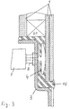
- the pane (see FIG. 3) is glued into the frame structure, the adhesive taking on sealing functions after hardening and also being able to transmit forces between the frame and pane.
- a folded pressure hose 4 is inserted, which is connected to a pyrotechnic gas generator 7 via a connector 8.
- a gas-generating material is arranged which, after ignition by an electrical ignition element, generates a compressed gas.
- This compressed gas passes through the connector 8 into the pressure hose 4 and inflates it. Since the resulting volume of the pressure hose 4 is larger than the cavity available for the pressure hose 4, the forces acting on the threaded screw 5 tear it off and the window pane 1 is pushed out of the frame element 3.
- a predetermined breaking point 10 is arranged in the threaded screw 5, so that the predetermined breaking point 10 breaks open and the window pane 1 is pushed out of the frame element 3 without being destroyed.
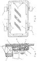
- FIG. 2 shows a preferred arrangement of the gas generators 7.
- Two generators 7 are arranged on each longitudinal side of the window pane 1, each of which is connected to the pressure hose 4 via a connector 8.
- the fastening element consisting of threaded screw 5 and nut 6 is indicated by reference number 11 (see FIG. 1).
- the window pane 1 can be connected to the frame element 3 via a holding device, not shown.
- the adhesive is designated by the reference symbol 15 and is arranged between the frame element 3 and the window pane 1.
- the pressure hose 4 is embedded in the adhesive 15.
- the adhesive 15 can also advantageously be shaped as a cavity, so that the cavity takes over the function of the pressure hose and no special pressure hose is required. If compressed gas gets into this cavity or into the pressure hose, it expands and the window pane 1 is pressed out of the frame element 3.
- the other reference symbols in FIG. 3 denote the same objects as in FIG. 1.
Landscapes
- Engineering & Computer Science (AREA)
- Mechanical Engineering (AREA)
- Health & Medical Sciences (AREA)
- General Health & Medical Sciences (AREA)
- Business, Economics & Management (AREA)
- Emergency Management (AREA)
- Window Of Vehicle (AREA)
- Securing Of Glass Panes Or The Like (AREA)
- Power-Operated Mechanisms For Wings (AREA)
- Emergency Lowering Means (AREA)
Abstract
Die Erfindung betrifft ein Verfahren zum Entriegeln einer Fensterscheibe (1) die über ein Befestigungselement an einem Rahmenelement (3) festliegt und zwischen der Fensterscheibe (1) und dem Rahmenelement (3) ein aufblasbarer Druckschlauch (4) angeordnet ist, der im aufgeblasenen Zustand die Fensterscheibe (1) aus dem Rahmenelement (3) drückt. Zum sicheren und besseren Entriegeln der Fensterscheibe wird vorgeschlagen, daß der Druckschlauch (4) im Betätigungsfall von zumindest einem pyrotechnischen Gasgenerator (7) aufgeblasen wird. <IMAGE>The invention relates to a method for unlocking a window pane (1) which is fixed via a fastening element to a frame element (3) and between the window pane (1) and the frame element (3) an inflatable pressure hose (4) is arranged, which in the inflated state Presses the window pane (1) out of the frame element (3). For safe and better unlocking of the window pane, it is proposed that the pressure hose (4) be inflated by at least one pyrotechnic gas generator (7) when actuated. <IMAGE>
Description
Die Erfindung betrifft ein Verfahren zum Entriegeln einer Fensterscheibe mit einem aufblasbaren Druckschlauch nach dem Oberbegriff des Anspruchs 1.The invention relates to a method for unlocking a window pane with an inflatable pressure hose according to the preamble of
Moderne Eisenbahnwaggons werden häufig mit Klimaanlagen ausgestattet. Dies bedingt die Forderung nach einer höheren Wärmedämmung der Fenster. Bei Hochgeschwindigkeitszügen kommt zusätzlich noch die Forderung nach einer guten Schallisolierung und einer großen dynamischen Festigkeit (Ein-/Ausfahrt von Tunnels, Züge auf dem Gegengleis) hinzu. Aufgrund dieser gestiegenen Anforderungen werden Fenster verlangt, die eine so hohe Stabilität besitzen, daß sie manuell (vor allem in der Dunkelheit oder bei Panik-Situationen) nicht mehr zerstört bzw. geöffnet werden können. Um diese Forderungen erfüllen zu können, werden in modernen Hochgeschwindigkeitszügen Isolierglasfenster verbunden mit Verbundglasscheiben verwendet. In gepanzerten Kraftfahrzeugen ist diese Problematik aufgrund der Verwendung von beschußhemmenden Scheiben besonders ausgeprägt.Modern railroad cars are often equipped with air conditioning. This calls for a higher level of thermal insulation for the windows. In the case of high-speed trains, there is also the requirement for good sound insulation and great dynamic strength (entry / exit of tunnels, trains on the opposite track). Due to these increased requirements, windows are required which are so stable that they cannot be destroyed or opened manually (especially in the dark or in panic situations). In order to meet these requirements, insulating glass windows connected with laminated glass panes are used in modern high-speed trains. This problem is particularly pronounced in armored motor vehicles due to the use of bullet-resistant windows.
Aus der DE-A1-39 25 430 ist eine Entriegelungsvorrichtung für eine Fensterscheibe bekannt, die über ein Dichtungsprofil mit einem Rahmenelement verbunden ist, wobei die Fensterscheibe über ein Befestigungselement am Rahmenelement befestigt ist. In diesem oder am Befestigungselement ist ein mit Gas füllbarer, verformbarer Schlauch angeordnet, der im aufgeblasenen Zustand die Befestigung der Fensterscheibe aufreißt, so daß die Fensterscheibe aus dem Rahmenelement fällt.From DE-A1-39 25 430 an unlocking device for a window pane is known, which is connected to a frame element via a sealing profile, the window pane being fastened to the frame element via a fastening element. A gas-fillable, deformable hose is arranged in this or on the fastening element, which in the inflated state tears open the fastening of the window pane so that the window pane falls out of the frame element.
Der Erfindung liegt die Aufgabe zugrunde, ein Verfahren zum Entriegeln einer Fensterscheibe nach dem Oberbegriff des Anspruchs 1 zu schaffen, die mit einfachen Mitteln nahezu 100 %-ig sicherstellt, daß im Notfall die Fensterscheibe aus dem Rahmen fällt.The invention has for its object to provide a method for unlocking a window pane according to the preamble of
Erfindungsgemäß wird diese Aufgabe dadurch gelöst, daß der Druckschlauch im Betätigungsfall von zumindest einem pyrotechnischen Gasgenerator aufgeblasen wird.According to the invention, this object is achieved in that the pressure hose is inflated by at least one pyrotechnic gas generator when actuated.
Gasgeneratoren werden heute in hohen Stückzahlen produziert und sind absolut zuverlässig. Außerdem benötigen sie nur sehr wenig Platz, so daß diese direkt in den Rahmen der Fensterscheibe integriert werden können. Die Zündung erfolgt elektrisch entweder zentral für mehrere Fensterscheiben z.B. durch eine Steuerelektronik oder aber dezentral für jede Fensterscheibe getrennt.Gas generators are now produced in large numbers and are absolutely reliable. In addition, they take up very little space so that they can be integrated directly into the frame of the window pane. The ignition is electrical either centrally for several window panes e.g. separated by control electronics or decentrally for each window pane.
Vorteilhafterweise wird der Druckschlauch im Betätigungsfall von mehr als einem Gasgenerator aufgeblasen. Hierdurch ist die Sicherheit nochmals erheblich gesteigert, da bei Ausfall eines Gasgenerators der oder die anderen dessen Funktion übernehmen. In einer speziellen vorteilhaften Ausführungsform wird der Druckschlauch von zwei auf jeder Längsseite der Fensterscheibe angeordneten Gasgeneratoren aufgeblasen.When actuated, the pressure hose is advantageously inflated by more than one gas generator. This further increases safety considerably, since one or the other takes over its function in the event of a gas generator failure. In a special advantageous embodiment, the pressure hose is inflated by two gas generators arranged on each long side of the window pane.
Hierbei ist zweckmäßigerweise jeder Gasgenerator über ein Anschlußstück mit dem Druckschlauch verbunden. Erfindungsgemäß kann jedoch auch der Druckschlauch über mehrere Anschlußstücke mit z.B. einem einzigen Gasgenerator verbunden sein.In this case, each gas generator is expediently connected to the pressure hose via a connector. According to the invention, however, the pressure hose can also be connected to e.g. be connected to a single gas generator.
In bevorzugter Ausführungsform ist die Fensterscheibe in Auswurfrichtung über eine Feder kraftbeaufschlagt. Hierdurch ist ein vollständiges Auswerten der Fensterscheibe auch unter ungünstigen Bedingungen sichergestellt.In a preferred embodiment, the window pane is acted upon by a spring in the ejection direction. This ensures a complete evaluation of the window pane even under unfavorable conditions.
Erfindungsgemäß läßt sich dieses Verfahren vorteilhaft für Fensterscheiben in Eisenbahnwaggons oder in Kraftfahrzeugen verwenden. Besonders wenn die Fensterscheiben eingeklebt sind, d.h. wenn das Befestigungselement ein Klebstoff ist, ist dieses Verfahren zweckmäßig, da der Klebstoff durch die mechanischen Kräfte, die der Druckschlauch auf ihn ausübt, in eine für ihn ungünstige Weise belastet wird. Die Klebeverbindung wird so gelöst.According to the invention, this method can be used advantageously for window panes in railroad cars or in motor vehicles. Especially if the window panes are glued in, i.e. if the fastening element is an adhesive, this method is expedient since the adhesive is loaded in an unfavorable manner by the mechanical forces which the pressure hose exerts on it. The adhesive connection is released.
Weitere Merkmale der Erfindung ergeben sich aus den Figuren, die nachfolgend beschrieben werden. Es zeigt:
- Fig. 1
- einen Ausschnitt aus einer Fensterscheibe für Eisenbahnwaggons mit einem aufblasbaren Druckschlauch,
- Fig. 2
- eine beispielhafte Anordnung von Gasgeneratoren am Druckschlauch und
- Fig. 3
- eine Ausführungsform mit eingeklebter Fensterscheibe.
- Fig. 1
- a section of a window pane for railway wagons with an inflatable pressure hose,
- Fig. 2
- an exemplary arrangement of gas generators on the pressure hose and
- Fig. 3
- an embodiment with glued window.
Die Figur 1 zeigt eine Entriegelungsvorrichtung mit einer Fensterscheibe 1, die aus einer Isolierglas-Verbundscheibe mit drei Scheiben besteht. Zwei nach außen gerichtete Verbundglasscheiben sind über einen Abstandshalter 20 mit einer dritten Scheibe verbunden. Über ein Dichtungsprofil 2 ist die Fensterscheibe 1 mit einem Rahmenelement 3 verbunden. Die eigentliche Befestigung erfolgt über ein Befestigungselement, welches aus einer Gewindeschraube 5 und einer Mutter 6 besteht. Die Gewindeschraube 5 besteht aus einem zylinderförmigen Rohr mit einem Außengewinde und aus einer kragenförmigen endseitigen Erweiterung. Zur Befestigung ist die zur Fensterscheibe 1 gewandte kragenförmige Erweiterung zwischen die Verbundscheiben eingesetzt. Über die Mutter 6, die auf das Gewinde der Gewindeschraube 5 aufgeschraubt ist, ist die Gewindeschraube 5 und damit die Fensterscheibe 1 mit dem Rahmenelement 3 fest verbunden, da die Gewindeschraube 5 das Rahmenelement 3 durchragt und die Mutter 6 von außen über einen Distanzring auf dem Rahmenelement 3 aufliegt.FIG. 1 shows an unlocking device with a
Zum besseren Auswerfen der Fensterscheibe ist die Gewindeschraube 5 von einer Feder 9 umgeben, die sich einerseits am Rahmenelement 3 und andererseits an der Fensterscheibe 1 in Auswurfrichtung abstützt.For better ejection of the window pane, the threaded
Alternativ wird die Scheibe (siehe Fig. 3) in die Rahmenstruktur geklebt, wobei der Kleber nach dem Aushärten sowohl Dichtfunktionen übernimmt, als auch Kräfte zwischen Rahmen und Scheibe übertragen kann.Alternatively, the pane (see FIG. 3) is glued into the frame structure, the adhesive taking on sealing functions after hardening and also being able to transmit forces between the frame and pane.
In einem Hohlraum zwischen dem Rahmenelement 3 und der Fensterscheibe 1 bzw. dem Dichtungsprofil 2 ist ein gefalteter Druckschlauch 4 eingesetzt, der über ein Anschlußstück 8 mit einem pyrotechnischen Gasgenerator 7 in Verbindung steht. Im Gasgenerator 7 ist, wie allgemein üblich, ein gaserzeugendes Material angeordnet, welches nach Zündung durch ein elektrisches Anzündelement ein Druckgas erzeugt. Dieses Druckgas gelangt über das Anschlußstück 8 in den Druckschlauch 4 und bläst diesen auf. Da das sich daraus ergebende Volumen des Druckschlauches 4 größer ist als der für den Druckschlauch 4 zur Verfügung stehende Hohlraum, wird durch die auf die Gewindeschraube 5 wirkenden Kräfte diese abgerissen und die Fensterscheibe 1 aus dem Rahmenelement 3 gestoßen. Vorteilhafterweise ist in der Gewindeschraube 5 eine Sollbruchstelle 10 angeordnet, so daß im Betätigungsfall die Sollbruchstelle 10 aufbricht und die Fensterscheibe 1 unzerstört aus dem Rahmenelement 3 gestoßen wird.In a cavity between the
Figur 2 zeigt eine bevorzugte Anordnung der Gasgeneratoren 7. Auf jeder Längsseite der Fensterscheibe 1 sind zwei Generatoren 7 angeordnet, die jeweils über ein Anschlußstück 8 mit dem Druckschlauch 4 verbunden sind. Mit dem Bezugszeichen 11 ist das Befestigungselement bestehend aus Gewindeschraube 5 und Mutter 6 angedeutet (siehe Fig. 1).FIG. 2 shows a preferred arrangement of the
Damit keine Personen beim Auswerfen der Fensterscheibe 1 verletzt werden, kann die Fensterscheibe 1 mit dem Rahmenelement 3 über eine nicht gezeigte Haltevorrichtung verbunden sein.So that no one is injured when ejecting the
Fig. 3 zeigt eine Ausführungsform mit eingeklebter Fensterscheibe 1. Der Klebstoff ist mit dem Bezugszeichen 15 bezeichnet und ist zwischen dem Rahmenelement 3 und der Fensterscheibe 1 angeordnet. Im Klebstoff 15 ist der Druckschlauch 4 eingebettet. Der Klebstoff 15 kann auch vorteilhafterweise als Hohlraum geformt sein, so daß der Hohlraum die Funktion des Druckschlauchs übernimmt und kein spezieller Druckschlauch erforderlich ist. Gelangt Druckgas in diesen Hohlraum bzw. in den Druckschlauch, dann weitet sich dieser und die Fensterscheibe 1 wird aus dem Rahmenelement 3 gedrückt. Die weiteren Bezugszeichen in der Fig. 3 bezeichnen dieselben Gegenstände wie in Fig. 1.3 shows an embodiment with the
Unter einem Klebstoff 15 ist z. B. auch eine Silikonmasse verstanden.Under an adhesive 15 z. B. also understood a silicone compound.
Claims (7)
Applications Claiming Priority (4)
| Application Number | Priority Date | Filing Date | Title |
|---|---|---|---|
| DE19525833 | 1995-07-15 | ||
| DE19525833 | 1995-07-15 | ||
| DE19544886A DE19544886A1 (en) | 1995-07-15 | 1995-12-01 | Method for releasing window pane - involves use of pressurised tube operated with at least one pyrotechnic gas generator, lifting window pane from window frame |
| DE19544886 | 1995-12-01 |
Publications (2)
| Publication Number | Publication Date |
|---|---|
| EP0754584A2 true EP0754584A2 (en) | 1997-01-22 |
| EP0754584A3 EP0754584A3 (en) | 1998-04-15 |
Family
ID=26016840
Family Applications (1)
| Application Number | Title | Priority Date | Filing Date |
|---|---|---|---|
| EP96111076A Withdrawn EP0754584A3 (en) | 1995-07-15 | 1996-07-10 | Method to unlock a window pane with an inflatable pressure hose |
Country Status (4)
| Country | Link |
|---|---|
| US (1) | US5746026A (en) |
| EP (1) | EP0754584A3 (en) |
| JP (1) | JPH0930416A (en) |
| CN (1) | CN1145975A (en) |
Cited By (1)
| Publication number | Priority date | Publication date | Assignee | Title |
|---|---|---|---|---|
| DE19754814A1 (en) * | 1997-12-10 | 1999-06-17 | Dynamit Nobel Ag | Release mechanism for window in building |
Families Citing this family (15)
| Publication number | Priority date | Publication date | Assignee | Title |
|---|---|---|---|---|
| DE19829737A1 (en) * | 1998-07-03 | 2000-01-13 | Huebner Gummi & Kunststoff | Window frame profile for a vehicle |
| GB9901573D0 (en) * | 1999-01-26 | 1999-03-17 | Graham Steven J | Emergency escape system |
| FR2789947B1 (en) * | 1999-02-22 | 2001-04-13 | Saint Gobain Vitrage | DEVICES FOR FIXING A GLASS FOR A MOTOR VEHICLE |
| GB0216304D0 (en) * | 2002-07-13 | 2002-08-21 | Ford Global Tech Inc | A door assembly for a motor vehicle |
| EP1418121A1 (en) * | 2002-11-06 | 2004-05-12 | Eaton Fluid Power GmbH | Emergency door actuator system |
| CA2537368C (en) * | 2006-02-10 | 2011-03-08 | Peters, Timothy | Emergency escape window |
| US8066319B2 (en) | 2006-12-01 | 2011-11-29 | Bae Systems Land & Armaments, L.P. | Vehicle emergency egress assembly |
| US8632120B2 (en) | 2006-12-01 | 2014-01-21 | Bae Systems Land & Armaments L.P. | Universal latch mechanism |
| EP2269857A1 (en) * | 2009-06-30 | 2011-01-05 | Eurocopter Deutschland GmbH | Emergency Jettison window pane and associated ejection system |
| WO2011046668A1 (en) | 2009-10-13 | 2011-04-21 | Ppg Industries Ohio, Inc. | Vehicle emergency egress system |
| US8397431B2 (en) * | 2010-10-06 | 2013-03-19 | Eurocopter Deutschland Gmbh | Emergency jettison window pane and associated ejection system |
| KR101255721B1 (en) * | 2010-10-11 | 2013-04-17 | 유로캅터 도이칠란트 게엠베하 | Emergency jettison window pane and associated ejection system |
| CN103847470B (en) * | 2014-01-22 | 2016-04-13 | 刘升旗 | The mounting structure that a kind of vehicle front-and-back stop glass can depart from instantaneously |
| IT201600073637A1 (en) * | 2016-07-14 | 2018-01-14 | Agt S R L | Coupling system for removably coupling a panel of transparent material, in particular a glass panel, to a frame, in particular a frame of a railway rolling stock, and a method for applying said transparent material panel to said frame. |
| CN108284810B (en) * | 2018-03-26 | 2024-01-16 | 吉林大学 | An automatic pop-up escape device for automobile windshield and window glass |
Family Cites Families (9)
| Publication number | Priority date | Publication date | Assignee | Title |
|---|---|---|---|---|
| US3150749A (en) * | 1961-05-15 | 1964-09-29 | Parke Davis & Co | Explosion venting construction |
| US3442048A (en) * | 1967-03-17 | 1969-05-06 | Enrique Elias | Ejectable window for a passenger vehicle |
| US3737193A (en) * | 1971-10-22 | 1973-06-05 | R Cain | Windshield ejector for vehicles |
| FR2445799A1 (en) * | 1979-01-04 | 1980-08-01 | Aerospatiale | ICE PROVIDED WITH A PYROTECHNIC CUTTING DEVICE |
| US4635396A (en) * | 1986-04-28 | 1987-01-13 | O. M. Edwards Company, Inc. | Bus window release mechanism |
| FR2634171B1 (en) * | 1988-07-13 | 1990-09-28 | Aerospatiale | PYROTECHNIC SYSTEM FOR PROVIDING A EMERGENCY EXIT IN A WALL OF AN AIRCRAFT AND AIRCRAFT EQUIPPED WITH SAID SYSTEM |
| DE3925430A1 (en) * | 1989-08-01 | 1991-02-07 | Messerschmitt Boelkow Blohm | Vehicle emergency exit window - has frame with at least one deformable, hollow tube, which when inflated releases window glass from frame |
| DE4016611A1 (en) * | 1990-05-23 | 1991-11-28 | Audi Ag | SAFETY DEVICE ON A MOTOR VEHICLE |
| DE4321378C2 (en) * | 1993-06-26 | 1997-01-02 | Daimler Benz Aerospace Ag | Window pane with assigned crushing device |
-
1996
- 1996-07-10 EP EP96111076A patent/EP0754584A3/en not_active Withdrawn
- 1996-07-12 JP JP8183622A patent/JPH0930416A/en active Pending
- 1996-07-13 CN CN96110732A patent/CN1145975A/en active Pending
- 1996-07-15 US US08/683,630 patent/US5746026A/en not_active Expired - Fee Related
Cited By (1)
| Publication number | Priority date | Publication date | Assignee | Title |
|---|---|---|---|---|
| DE19754814A1 (en) * | 1997-12-10 | 1999-06-17 | Dynamit Nobel Ag | Release mechanism for window in building |
Also Published As
| Publication number | Publication date |
|---|---|
| CN1145975A (en) | 1997-03-26 |
| JPH0930416A (en) | 1997-02-04 |
| US5746026A (en) | 1998-05-05 |
| EP0754584A3 (en) | 1998-04-15 |
Similar Documents
| Publication | Publication Date | Title |
|---|---|---|
| EP1719684B1 (en) | Central buffer coupling for railway vehicles | |
| DE4016611C2 (en) | ||
| DE102007029097B4 (en) | Rollover protection system for motor vehicles with at least one pyrotechnic deployable rollover body | |
| DE19654559C2 (en) | Shock absorbing device for a motor vehicle | |
| DE102008053229A1 (en) | Tensioning device for use in belt retractor for safety belt in motor vehicle, has piston element slidably arranged in channel and comprising elastic sealing element connected with dimensionally stable spherical base body | |
| DE19757363B4 (en) | Airbag system for motor vehicles | |
| EP2611690A1 (en) | Seat fixing device for fixing a vehicle seat, and vehicle seat comprising such a seat fixing device | |
| DE19544886A1 (en) | Method for releasing window pane - involves use of pressurised tube operated with at least one pyrotechnic gas generator, lifting window pane from window frame | |
| EP0748709A1 (en) | Unlocking device for a window pane, especially for railway carriages, with a slider | |
| EP0756970B1 (en) | Crash-impulse transmitting device | |
| DE19960041A1 (en) | Emergency exit device for a motor vehicle | |
| EP1547873B1 (en) | Rollover protective system for cars with a movable rolloverbody | |
| DE19632610A1 (en) | Emergency release system for window of high-speed train | |
| DE20218869U1 (en) | Seat belt tensioning device, comprising pushing element moving towards piston and deforming pipe in case of impact | |
| DE2120042A1 (en) | Safety device for automobiles | |
| EP0529433A1 (en) | Shock absorbing device, in particular for vehicles | |
| DE19803440A1 (en) | Emergency exit for safety motor vehicles | |
| DE29613269U1 (en) | Airbag module for a vehicle occupant restraint system | |
| WO2003106234A1 (en) | Safety device for removing a pin, especially a pedal pin in a motor vehicle | |
| DE10311035B4 (en) | Impact protection arrangement for motor vehicle occupants | |
| EP0748733A1 (en) | Unlocking device for a window pane, especially for railway carriages, with a sliding or swinging window pane | |
| EP0748710A1 (en) | Unlocking device for a window pane, especially for railway carriages, with an endless cord or strap | |
| DE102024104378B3 (en) | Component arrangement for a motor vehicle, method for producing such a component arrangement and method for dismantling a component arrangement | |
| DE19703820A1 (en) | Pressure levelling device for release of airbag | |
| DE10039801B4 (en) | Vehicle roof, in particular for a motor vehicle |
Legal Events
| Date | Code | Title | Description |
|---|---|---|---|
| PUAI | Public reference made under article 153(3) epc to a published international application that has entered the european phase |
Free format text: ORIGINAL CODE: 0009012 |
|
| AK | Designated contracting states |
Kind code of ref document: A2 Designated state(s): DE FR GB IT SE |
|
| PUAL | Search report despatched |
Free format text: ORIGINAL CODE: 0009013 |
|
| AK | Designated contracting states |
Kind code of ref document: A3 Designated state(s): DE FR GB IT SE |
|
| 17P | Request for examination filed |
Effective date: 19981005 |
|
| 17Q | First examination report despatched |
Effective date: 19991209 |
|
| STAA | Information on the status of an ep patent application or granted ep patent |
Free format text: STATUS: THE APPLICATION IS DEEMED TO BE WITHDRAWN |
|
| 18D | Application deemed to be withdrawn |
Effective date: 20010206 |