EP0754528B1 - Tournevis dynamométrique à alarme sonore et/ou visuelle - Google Patents
Tournevis dynamométrique à alarme sonore et/ou visuelle Download PDFInfo
- Publication number
- EP0754528B1 EP0754528B1 EP19960420207 EP96420207A EP0754528B1 EP 0754528 B1 EP0754528 B1 EP 0754528B1 EP 19960420207 EP19960420207 EP 19960420207 EP 96420207 A EP96420207 A EP 96420207A EP 0754528 B1 EP0754528 B1 EP 0754528B1
- Authority
- EP
- European Patent Office
- Prior art keywords
- torque
- screwdriver according
- torque screwdriver
- driving tube
- disposed
- Prior art date
- Legal status (The legal status is an assumption and is not a legal conclusion. Google has not performed a legal analysis and makes no representation as to the accuracy of the status listed.)
- Expired - Lifetime
Links
Images


Classifications
-
- B—PERFORMING OPERATIONS; TRANSPORTING
- B25—HAND TOOLS; PORTABLE POWER-DRIVEN TOOLS; MANIPULATORS
- B25B—TOOLS OR BENCH DEVICES NOT OTHERWISE PROVIDED FOR, FOR FASTENING, CONNECTING, DISENGAGING, OR HOLDING
- B25B23/00—Details of, or accessories for, spanners, wrenches, screwdrivers
- B25B23/14—Arrangement of torque limiters or torque indicators in wrenches or screwdrivers
- B25B23/142—Arrangement of torque limiters or torque indicators in wrenches or screwdrivers specially adapted for hand operated wrenches or screwdrivers
- B25B23/1422—Arrangement of torque limiters or torque indicators in wrenches or screwdrivers specially adapted for hand operated wrenches or screwdrivers torque indicators or adjustable torque limiters
- B25B23/1425—Arrangement of torque limiters or torque indicators in wrenches or screwdrivers specially adapted for hand operated wrenches or screwdrivers torque indicators or adjustable torque limiters by electrical means
-
- B—PERFORMING OPERATIONS; TRANSPORTING
- B25—HAND TOOLS; PORTABLE POWER-DRIVEN TOOLS; MANIPULATORS
- B25B—TOOLS OR BENCH DEVICES NOT OTHERWISE PROVIDED FOR, FOR FASTENING, CONNECTING, DISENGAGING, OR HOLDING
- B25B23/00—Details of, or accessories for, spanners, wrenches, screwdrivers
- B25B23/14—Arrangement of torque limiters or torque indicators in wrenches or screwdrivers
- B25B23/142—Arrangement of torque limiters or torque indicators in wrenches or screwdrivers specially adapted for hand operated wrenches or screwdrivers
- B25B23/1422—Arrangement of torque limiters or torque indicators in wrenches or screwdrivers specially adapted for hand operated wrenches or screwdrivers torque indicators or adjustable torque limiters
- B25B23/1427—Arrangement of torque limiters or torque indicators in wrenches or screwdrivers specially adapted for hand operated wrenches or screwdrivers torque indicators or adjustable torque limiters by mechanical means
Definitions
- the invention relates to an electromechanical torque screwdriver according to the preamble of claim 1.
- torque screwdrivers in which a means of elastic return, such as Belleville washers or helical spring, with adjustable setting by a micrometric screw, determines the triggering threshold of an interposed torque limiter between the handle and the tip of the screwdriver, and comprising rollers, balls or ramps complementary.
- a means of elastic return such as Belleville washers or helical spring
- Such torque screwdrivers are in particular described in the French patents 1,569,991 and FR-A-72 07870.
- This triggering technique generates a very strong shock in the screwdriver noticeable and a drop in torque but has two drawbacks.
- the first results from permanent compression of the elastic return means which, over time, can cause fatigue of the material of this means, and cause inaccuracies in measured.
- the second drawback comes from the adjustment by micrometric screw which is long and difficult for an untrained operator.
- the diameter of the graduated sector must be large, which leads to excessive bulk of the screwdriver. Furthermore, this type of screwdriver does not have means alerting the operator that the desired torque is reached, and therefore requires a permanent reading of the graduated sector.
- the object of the present invention is to remedy the drawbacks of these two types of screwdrivers, while combining their advantages.
- a torque screwdriver comprises, on the one hand, a driving tube mounted to rotate freely in a tubular handle body, and having, at its free end, a nozzle for receiving a removable member rotational drive, on the other hand, a torsion rod arranged essentially at the inside of the coach tube and one end of which is linked to this tube while its other end, disposed in the handle body, is linked to this body, and, moreover, means which, linked to the handle body, cooperate with means linked to the driving tube to indicate that the tightening torque is reached.
- the end of the rod torsion, arranged in the handle body is linked to the latter with the interposition of means of electrical insulation, so as to constitute with the driving tube one of the branches of a electrical circuit leading to a battery disposed inside the handle body, while the other branch of the electrical circuit, powered by the same battery, includes the body of handle carrying an internal stud, of electrical contact and of adjustable position, this stud being able to cooperate with at least one of the faces of a substantially longitudinal groove, formed in a conductive sleeve integral with the driving tube and electrically insulated of the body, to trigger alarm means arranged on one of the branches of the circuit.
- the trigger threshold is defined by the contact of the stud with one of the faces of the groove of the sleeve linked to the driving tube. This firm contact the electrical circuit which then supplies the alarm, sound or light means.
- the value of the detected torque is adjusted by modifying the angular travel between the stud at rest and the face opposite the groove.
- the contact pad is carried by a external pusher which, movable in a lumen of the tubular body, is provided with a mark cooperating with graduations provided on the external face of the body, at least one of the faces, respectively of contact of the groove and the light, being longitudinal, while that the other is made up of a large propeller fragment to increase the resolution of the graduation reading scale.
- This arrangement allows, in a tool having a reduced diametrical size, and while the maximum angle of twist is small, and for example less than 30 ° to limit the fatigue rate of the torsion blade, to obtain an amplification of the interval between the graduations of the reading scale and, consequently, to increase the accuracy of the positioning of the stud and the accuracy of the measurement.
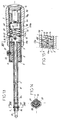
- the screwdriver load cell is made up of a metallic tubular body 2, locally covered by a comfort handle 3 and at the end of a hollow plug 4, and of a driving tube 6, of polygonal or cylindrical section.
- the free end of this tube is provided with a housing 7 whose internal profile is adapted to receive hexagon nuts or any other imprint form.
- This driving tube is metallic and is integral at its other end, a metal sleeve 8 which is mounted to rotate freely inside the front end of body 2, with interposition of insulating washers 9. This assembly tolerates sliding longitudinal of sleeve 8 and tube 6 to absorb the slight reduction in length of the torsion bar, when twisted.
- This torque screwdriver is therefore equipped with a torsion bar consisting by a leaf spring 10, almost the entire length of which is disposed inside the driving tube 6.
- This blade of square, rectangular or cylindrical section, is provided with its front end of an enlarged head 10a linked in rotation, and in translation, by example, by welding or crimping at the anterior end of the tube 6.
- the posterior end of the blade is also provided with an enlarged head 10b, of larger dimensions than that 10a, being housed in the extreme slot 12 of a socket 13 in insulating material, and in particular in synthetic material.
- a transverse pin 14 ensures the connection in rotation and translation of the head 10b with the tubular body 2.
- This pin passes through the sleeve 13 right through and engages, by its ends, in the appropriate bores of the body 2. In its crossing of the head 10b, it is isolated from this head by a ring 15 of insulating material, visible in Figures 1 and 2.
- the ring 15 is composed of two integral elements each of one of the parts of the socket 13.
- the socket 13 serves as a housing for a stick battery 16, one of the terminals of which the positive terminal occurrence, defines the first branch of an electrical circuit comprising the torsion blade 10, the driving tube 6, the sleeve 8, while the negative terminal of the battery comes into contact with another branch composed of a blade conductive 17 supplying an audible warning 18, of a conductive bar 19 going from the horn 18 at the rear end of the metal body 2.
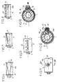
- the means for closing the two branches of this electrical circuit are constituted by means which make it possible to determine the tightening torque from which the horn 18 should come on. These means are in the form of execution shown, consisting of a contact pad 20 made of conductive metal and bonded electrically to the body 2, and by one of the faces 21, 22 of a gutter 11 arranged substantially longitudinally in the sleeve 8.
- the contact pad 20 is slidably mounted in a longitudinal slot 23 formed at the anterior end of the body 2, and is secured, by a radial screw 24, with a pusher 25 made of synthetic material.
- This pusher has two elastic wings 26 (figure 5) which make it possible to make up for the functional clearances and slide, with gentle friction, against the outside of the body.
- the actuation of screw 24 makes it possible to adjust the tightening elastic wings 26 and the play of the pusher, and possibly blocking the pusher in a position for temporarily fixing the torque at a determined value.
- the pusher 25 is provided with at least one mark 27 cooperating with a graduation 28.
- it has two marks cooperating with two graduations, one in Newton meters, the other in foot-pounds.
- At least one of the faces of the gutter 11, and in this case the face 21, is constituted by a fragment of propeller to big step to increase the resolution of the graduation reading scale.
- This propeller allows to distribute, over most of the length of the sleeve 8, the scale of reading. Therefore, it has much more intervals between graduations spaced apart if this graduation were distributed circularly over a graduated sector extending on an arc ⁇ corresponding to the maximum angle of torsion, and shown in Figure 4, having a value less than 30 °.
- Another advantage of this construction is that it is compact and improves reliability of measurement accuracy.
- Figure 3 shows that the light 23 for the sliding of the pad 20 comprises locally a buttonhole 23a allowing the vertical insertion of the contact pad 20. As shown in Figure 1, this light is obscured by the comfort handle 3, when this is placed on the tubular body 2, also preventing untimely disassembly of the pusher.
- the plug 4 partially covering the rear end of the body 2, it is linked to this body by at least one radial screw 30, so as to allow it to be dismantled to replace the battery 16.
- the gutter 11 of the sleeve 8 is equipped with only one helical face 21 allowing the control only of couples tightening screws to the right and not allowing to determine an unlocking torque.
- the rotation in the unlocking direction quickly brings the pad 20 into contact with the face 22 of the gutter 11 and, whatever the torque, triggers the alarm to encourage the rotation to stop, and to prevent the destruction of contact means, in case of error of direction of rotation.
- the sleeve 8 To allow the measurement of locking and unlocking torques, the sleeve 8 must be equipped, as shown in Figure 6, with a gutter 11 having two sides helical opposites, respectively 21a and 22a whose propellers are opposite and do not have necessarily the same step, therefore not the same reading scale.
- the gutter 11 of the sleeve 8 is provided, at least on one side, with a stepped ramp 32.
- This ramp is associated with a reading scale 28 of body 2 comprising zones corresponding to the stages of the ramp and advancing, by successive jumps, the value of the torque.
- Such a stepped ramp can also be used with a device of the type shown in FIGS. 9 and 10 in which the contact pad 20 is secured to a positioning finger 33 and to a push-button 34 recalled by spring 35.
- This positioning finger 33 is intended to penetrate, under the action of the spring of reminder 35, in bores 36 distributed along the lumen 23 of the tubular body 2.
- the trigger threshold is adjusted by successive jumps by pressing the pusher 34 for the positioning finger 33 to escape from the bore 36 corresponding, and allow the plunger 34 and the pad 20 to slide.
- This plunger special can also be fitted with elastic lips which, of the type shown 5, combine with or replace the spring.
- the gutter 11 has two lateral and longitudinal faces 21b, 22b, while it is the light 23c of the body 2 which is in a helix to obtain a better resolution of the reading scale. This embodiment allows to obtain the same advantages and results as that described with reference to Figures 1 to 5.
- the sleeve 8 has a gutter 11 with lateral and longitudinal faces 21b, 22b, as shown in FIG. 8, and the contact pad 20a is cylindrical and wedged eccentrically on a screw 40 screwed radially in the body 2, and associated with a locking nut 42. It is easily understood that by rotating the screw, the position of the face of the stud coming into contact with the lateral face of the opposite groove, and, consequently, the idle stroke of the handle relative to the muff.
- the adjusting nut is capped by a cap 41 ensuring the inviolability of the setting.
- the screwdriver torque is different from the previous one in that, in addition to the horn sound 18, it is provided with at least one warning light 43, and for example three LEDs arranged at 120 °. Furthermore, the horn 18 and the warning lights 43 are arranged in the central part of the body 2, and more precisely, in a cavity 44 formed in the rear part 13a of the insulating sleeve also comprising a front part 13b. As shown in Figure 15, the latter has the slot 12 receiving an enlarged head 10b of the torsion blade and, opposite this slot, a sound reflection cone 51.
- the part 13a is slidably mounted in the body 2 and is separated from part 13b by a space.
- the battery is in contact with a blade 46, integral with the horn 18, and a conductive plug 47, attached and fixed in the end of the body 2, either by thread or by bayonet lugs.
- the horn 18 is connected by an electrical circuit 48 to the horns luminous 43, and from there to the enlarged head 10b of the bending blade. This connection is ensured by a conductor 59 which passes through a groove 60 communicating with the slot 12 (FIG. 15).
- the driving tube 6 has an internal and external hexagonal section, so that the housing 7 provided at its end is also hexagonal and is capable of receiving removable end pieces 55 comprising a groove 56 able to cooperate with the two lugs 57, passing radially through the tube 6, with a retaining ring 58.
- FIG. 16 to 18 differs from previous by the shape of the gutter 11. Indeed, it is made in a room metallic which has, in cross section, the shape of a "U”, whose flared wings 64, 65 delimit the contact faces 21, 22 and whose core 66 is fixed, for example by welding by points 67, on one of the facets of the hexagonal profile constituting the tube 6.
- the wings 64, 65 are each secured to a return angled outside, respectively 64a and 65a, the aim of which is to facilitate the positioning of the part 63 on the tube 6 during welding at 67, and which are therefore not linked to this tube.
- the wings of the gutter thus formed have a faculty of elastic deformation their to prevent deterioration of the contact means, in case of handling errors screwdriver.
- Figure 16 shows that the tube 6 is carried by a ring 68 which is mounted free to rotate at the free end of the body 2.
- This ring is made of material synthetic, electrically insulating, and covers the anterior end of the body 2 to during the measurement, avoid closing the electrical circuit between the body 2 and the tube 6, by external conductive elements.
- the outer face of the body 2 is covered at its anterior end with an adhesive film 71 of insulating material, bearing the graduations of the reading scales.
Landscapes
- Engineering & Computer Science (AREA)
- Mechanical Engineering (AREA)
- Details Of Spanners, Wrenches, And Screw Drivers And Accessories (AREA)
- Measurement Of Current Or Voltage (AREA)
Description
Claims (13)
- Tournevis dynamométrique électromécanique comportant, d'une part, un tube entraíneur (6) monté libre en rotation dans un corps tubulaire de poignée (2), et présentant à son extrémité libre un embout (7) de réception d'un écrou ou organe amovible (55) d'entraínement en rotation, d'autre part, une tige de torsion (10) disposée pour l'essentiel à l'intérieur du tube entraíneur (6) et dont une extrémité (10a) est liée à ce tube alors que son autre extrémité (10b), disposée dans le corps de poignée (2), est liée à ce corps, et, de plus, des moyens qui, liés au corps de poignée, coopèrent avec des moyens liés au tube entraíneur pour indiquer que le couple de serrage est atteint, caractérisé en ce que l'extrémité postérieure (10b) de la tige de torsion (10) est disposée dans le corps (2) de poignée, et est liée à celui-ci avec interposition de moyens (13, 15) d'isolation électrique, de manière à constituer avec le tube entraíneur (6) l'une des branches d'un circuit électrique aboutissant à une pile (16) disposée à l'intérieur du corps de poignée (2), tandis que l'autre branche du circuit électrique, alimentée par la même pile (16), comprend le corps de poignée (2) portant un plot interne (20), de contact électrique et de position réglable, ce contact étant apte à coopérer avec au moins l'une des faces en vis à vis (21, 22) d'une gouttière (11) sensiblement longitudinale, solidaire du tube entraíneur (6) et isolée électriquement du corps (2), pour déclencher des moyens d'alarme (18, 43) disposés sur l'une des branches du circuit.
- Tournevis dynamométrique selon la revendication 1, caractérisé en ce que la tige de torsion (10) est constituée par une lame ressort présentant, dans sa partie postérieure dépassant du tube entraíneur (6) et à l'intérieur du corps de poignée (2), une tête élargie (10b) se logeant dans la fente extrême (12) d'une douille (13) en matière isolante disposée dans le corps (2) et servant de logement à la pile (16), cette tête étant liée au corps, en rotation et translation, par une goupille transversale (14) la traversant avec interposition d'une bague (15) en matériau isolant.
- Tournevis dynamométrique selon la revendication 2, caractérisé en ce que l'extrémité antérieure de la lame (10) est dotée d'une tête élargie (10a) liée à l'extrémité antérieure du tube entraíneur (6).
- Tournevis dynamométrique selon l'une quelconque des revendications 1 à 3, caractérisé en ce que le plot de contact (20) est porté par un poussoir externe (25) qui, déplaçable dans une lumière (23) du corps tubulaire (2), est muni d'au moins un repère (27) coopérant avec des graduations (28) ménagées sur la face externe du corps (2), au moins l'un des faces, respectivement de la gouttière (11) et de la lumière (23-2), étant longitudinale, tandis que l'autre est hélicoïdale pour augmenter la résolution de l'échelle de lecture de la graduation.
- Tournevis dynamométrique selon la revendication 4, caractérisé en ce que le poussoir (25) est réalisé en matière synthétique élastique et comporte deux ailes latérales (26) venant en appui sur le corps (2), de part et d'autre de la lumière (23), et dont la pression élastique d'application sur ce corps est déterminée par le serrage d'une vis (24) assurant la liaison de ce poussoir (25) avec le plot (20) de contact.
- Tournevis dynamométrique selon l'une quelconque des revendications 1 à 3, caractérisé en ce que la gouttière (11) ménagée dans le manchon (8) comporte, au moins d'un côté, une rampe étagée (32), tandis que le plot de contact (20) est porté par un poussoir externe (34) qui, déplaçable dans une lumière longitudinale (23) du corps, est muni d'un doigt (33) de positionnement dans des alésages (36) répartis sur la lumière, en coïncidence avec les étages de la rampe (32), et de moyens (35, 26) assurant le rappel élastique et radial du poussoir (34) vers l'extérieur pour favoriser l'engagement du doigt (33) de positionnement dans l'un des alésages (36) de la lumière.
- Tournevis dynamométrique selon l'une quelconque des revendications 1 à 3, caractérisé en ce que la gouttière (11) ménagée dans le manchon (8) présente des faces latérales (21b, 22b) parallèles, tandis que le plot de contact (20a) est cylindrique et est calé de manière excentrique sur une vis (40), vissée radialement dans le corps (2) et calable en position par un écrou (42).
- Tournevis dynamométrique selon l'une quelconque des revendications 1 à 7, caractérisé en ce que les moyens d'alarme sont constitués par un avertisseur sonore (18) disposé dans un bouchon creux (4) coiffant l'extrémité postérieure du corps (2) et interposé sur la branche du circuit électrique allant de l'une des bornes de la pile (16) au corps (2).
- Tournevis dynamométrique selon l'une quelconque des revendications 1 à 7, caractérisé en ce que les moyens d'alarme sont constitués par un avertisseur sonore (18) et par, au moins un avertisseur lumineux (43), disposés ensemble sur la branche du circuit électrique allant de l'une des bornes de la pile (16) à la lame de flexion (10) et logés ensemble dans le corps tubulaire (2).
- Tournevis dynamométrique selon la revendication 8, caractérisé en ce que la douille isolante est composée d'une part, d'une partie postérieure (13a) qui, montée coulissante dans le corps (2), comporte une cavité (44) de réception de l'avertisseur sonore, et d'autre part, d'une partie antérieure (13b) solidaire de la lame de torsion (10), ces deux parties étant séparées par un espace communiquant avec l'extérieur par des ouvertures radiales (50 et 52), ménagées respectivement dans le corps (2) et dans la poignée de confort (53), et dont certaines servent de logement à l'avertisseur lumineux (43).
- Tournevis dynamométrique selon l'une quelconque des revendications 1 à 10, caractérisé en ce que la gouttière (11) est réalisée dans une pièce métallique (63) présentant, en section transversale, la forme générale d'un "U" dont les ailes évasées (64, 65) délimitent les faces de contact (21, 22) et dont l'âme (66) est liée au tube entraíneur (6).
- Tournevis dynamométrique selon la revendication 11, caractérisé en ce que les ailes (64, 65) de la pièce (63) formant la gouttière sont élastiquement déformables.
- Tournevis dynamométrique selon l'une quelconque des revendications 1 à 12, caractérisé en ce que l'isolement de la partie postérieure du tube entraíneur et de la gouttière (11) par rapport au corps (2) est assuré par une bague antérieure (68), en matériau isolant, recouvrant l'extrémité antérieure de ce corps, la face extérieure de ce corps étant elle-même isolée par une pellicule adhésive (71) portant les graduations des échelles de lecture.
Applications Claiming Priority (2)
| Application Number | Priority Date | Filing Date | Title |
|---|---|---|---|
| FR9509048 | 1995-07-18 | ||
| FR9509048A FR2736858B1 (fr) | 1995-07-18 | 1995-07-18 | Tournevis dynamometrique electromecanique a alarme sonore et/ou visuelle |
Publications (2)
| Publication Number | Publication Date |
|---|---|
| EP0754528A1 EP0754528A1 (fr) | 1997-01-22 |
| EP0754528B1 true EP0754528B1 (fr) | 1998-11-18 |
Family
ID=9481375
Family Applications (1)
| Application Number | Title | Priority Date | Filing Date |
|---|---|---|---|
| EP19960420207 Expired - Lifetime EP0754528B1 (fr) | 1995-07-18 | 1996-06-20 | Tournevis dynamométrique à alarme sonore et/ou visuelle |
Country Status (4)
| Country | Link |
|---|---|
| EP (1) | EP0754528B1 (fr) |
| DE (1) | DE69600986D1 (fr) |
| ES (1) | ES2126372T3 (fr) |
| FR (1) | FR2736858B1 (fr) |
Families Citing this family (1)
| Publication number | Priority date | Publication date | Assignee | Title |
|---|---|---|---|---|
| DE102017109117B4 (de) * | 2017-04-27 | 2021-05-06 | Wiha Werkzeuge Gmbh | Schraubendreher und Verfahren zum Anziehen einer Schraube |
Family Cites Families (5)
| Publication number | Priority date | Publication date | Assignee | Title |
|---|---|---|---|---|
| US2205510A (en) * | 1938-04-07 | 1940-06-25 | Wolfram Karl | Change-over torque measuring tool for several measuring ranges |
| DE1603984A1 (de) * | 1968-01-25 | 1971-09-09 | Siemens Ag | Drehmoment-Schraubenzieher |
| US3678744A (en) * | 1969-11-14 | 1972-07-25 | Dresser Ind | Torque measuring hand screwdriver |
| FR2629383B1 (fr) * | 1988-04-01 | 1991-03-15 | Sam Outillage | Cle dynamometrique electromecanique |
| EP0393852B1 (fr) * | 1989-04-21 | 1994-01-12 | Mhh Engineering Co Ltd | Tournevis avec indication dynamométrique |
-
1995
- 1995-07-18 FR FR9509048A patent/FR2736858B1/fr not_active Expired - Fee Related
-
1996
- 1996-06-20 DE DE69600986T patent/DE69600986D1/de not_active Expired - Lifetime
- 1996-06-20 EP EP19960420207 patent/EP0754528B1/fr not_active Expired - Lifetime
- 1996-06-20 ES ES96420207T patent/ES2126372T3/es not_active Expired - Lifetime
Also Published As
| Publication number | Publication date |
|---|---|
| DE69600986D1 (de) | 1998-12-24 |
| FR2736858A1 (fr) | 1997-01-24 |
| ES2126372T3 (es) | 1999-03-16 |
| EP0754528A1 (fr) | 1997-01-22 |
| FR2736858B1 (fr) | 1997-10-10 |
Similar Documents
| Publication | Publication Date | Title |
|---|---|---|
| EP1961531B1 (fr) | Dispositif de serrage à bras de manoeuvre escamotable et appareil comportant un tel dispositif | |
| FR2738764A1 (fr) | Cle a vis avec dispositif d'affichage pour afficher une limite de force de torsion sur ce dernier | |
| EP0157666A1 (fr) | Potentiomètre rotatif, notamment de mesure de position angulaire | |
| CA2008956C (fr) | Cle de serrage perfectionnee en matiere plastique avec insert metallique | |
| FR2492993A1 (fr) | Perfectionnement aux charnieres de lunettes | |
| EP2243972A1 (fr) | Maillon d'attache à bague rotative verrouillable | |
| EP0898551B1 (fr) | Systeme de blocage temporaire de deplacement de deux corps l'un par rapport a l'autre, suivant au moins un sens d'une direction predeterminee | |
| FR2809237A1 (fr) | Connecteur electrique | |
| FR2667913A1 (fr) | Systeme pour l'assemblage d'au moins deux elements par vis ou analogue. | |
| FR2638791A1 (fr) | Verrou pour support d'equipement | |
| EP0754528A1 (fr) | Tournevis dynamométrique à alarme sonore et/ou visuelle | |
| FR2808552A1 (fr) | Serrure a deverrouillage mecanique et electrique | |
| EP3474085A1 (fr) | Dispositif de commande muni d'un module de détection de la position axiale de sa tige, et pièce d'horlogerie comprenant un tel dispositif de commande | |
| EP1649980B1 (fr) | Clé à limitation de couple améliorée | |
| FR2536689A1 (fr) | Tournevis comportant un mecanisme d'accouplement de sa tige | |
| EP0207833B1 (fr) | Bouton fileté à limiteur de couple | |
| FR2537878A1 (fr) | Procede et dispositif de tarage d'un mecanisme d'energisation d'une fixation de securite pour ski | |
| FR2580537A1 (fr) | Couteau fermant perfectionne | |
| FR2689256A1 (fr) | Couronne de montre. | |
| FR2514552A1 (fr) | Commutateur rotatif a positions multiples | |
| EP1458945B1 (fr) | Serrure electrique | |
| FR2533158A1 (fr) | Mecanisme d'entrainement d'outil en rotation pas a pas, en particulier pour cles a ecrous | |
| FR2900774A3 (fr) | Element moteur pour serrure electrique | |
| EP1845547A2 (fr) | Dispositif de manoeuvre bistable d'un arbre mobile et coupe-circuit de batterie comprenant un tel dispositif | |
| WO2002065497A1 (fr) | Dispositif de manoeuvre bistable en translation d'un axe mobile |
Legal Events
| Date | Code | Title | Description |
|---|---|---|---|
| PUAI | Public reference made under article 153(3) epc to a published international application that has entered the european phase |
Free format text: ORIGINAL CODE: 0009012 |
|
| 17P | Request for examination filed |
Effective date: 19960625 |
|
| AK | Designated contracting states |
Kind code of ref document: A1 Designated state(s): BE CH DE DK ES FR GB IT LI NL SE |
|
| GRAG | Despatch of communication of intention to grant |
Free format text: ORIGINAL CODE: EPIDOS AGRA |
|
| 17Q | First examination report despatched |
Effective date: 19980223 |
|
| GRAG | Despatch of communication of intention to grant |
Free format text: ORIGINAL CODE: EPIDOS AGRA |
|
| GRAH | Despatch of communication of intention to grant a patent |
Free format text: ORIGINAL CODE: EPIDOS IGRA |
|
| GRAH | Despatch of communication of intention to grant a patent |
Free format text: ORIGINAL CODE: EPIDOS IGRA |
|
| GRAA | (expected) grant |
Free format text: ORIGINAL CODE: 0009210 |
|
| AK | Designated contracting states |
Kind code of ref document: B1 Designated state(s): BE CH DE DK ES FR GB IT LI NL SE |
|
| PG25 | Lapsed in a contracting state [announced via postgrant information from national office to epo] |
Ref country code: SE Free format text: THE PATENT HAS BEEN ANNULLED BY A DECISION OF A NATIONAL AUTHORITY Effective date: 19981118 Ref country code: IT Free format text: LAPSE BECAUSE OF FAILURE TO SUBMIT A TRANSLATION OF THE DESCRIPTION OR TO PAY THE FEE WITHIN THE PRE;WARNING: LAPSES OF ITALIAN PATENTS WITH EFFECTIVE DATE BEFORE 2007 MAY HAVE OCCURRED AT ANY TIME BEFORE 2007. THE CORRECT EFFECTIVE DATE MAY BE DIFFERENT FROM THE ONE RECORDED.SCRIBED TIME-LIMIT Effective date: 19981118 Ref country code: GB Free format text: LAPSE BECAUSE OF NON-PAYMENT OF DUE FEES Effective date: 19981118 Ref country code: FR Free format text: THE PATENT HAS BEEN ANNULLED BY A DECISION OF A NATIONAL AUTHORITY Effective date: 19981118 |
|
| REG | Reference to a national code |
Ref country code: CH Ref legal event code: EP |
|
| REF | Corresponds to: |
Ref document number: 69600986 Country of ref document: DE Date of ref document: 19981224 |
|
| PG25 | Lapsed in a contracting state [announced via postgrant information from national office to epo] |
Ref country code: DK Free format text: LAPSE BECAUSE OF FAILURE TO SUBMIT A TRANSLATION OF THE DESCRIPTION OR TO PAY THE FEE WITHIN THE PRESCRIBED TIME-LIMIT Effective date: 19990218 |
|
| PG25 | Lapsed in a contracting state [announced via postgrant information from national office to epo] |
Ref country code: DE Free format text: LAPSE BECAUSE OF FAILURE TO SUBMIT A TRANSLATION OF THE DESCRIPTION OR TO PAY THE FEE WITHIN THE PRESCRIBED TIME-LIMIT Effective date: 19990219 |
|
| REG | Reference to a national code |
Ref country code: ES Ref legal event code: FG2A Ref document number: 2126372 Country of ref document: ES Kind code of ref document: T3 |
|
| GBV | Gb: ep patent (uk) treated as always having been void in accordance with gb section 77(7)/1977 [no translation filed] |
Effective date: 19981118 |
|
| PLBE | No opposition filed within time limit |
Free format text: ORIGINAL CODE: 0009261 |
|
| STAA | Information on the status of an ep patent application or granted ep patent |
Free format text: STATUS: NO OPPOSITION FILED WITHIN TIME LIMIT |
|
| 26N | No opposition filed | ||
| PG25 | Lapsed in a contracting state [announced via postgrant information from national office to epo] |
Ref country code: LI Free format text: LAPSE BECAUSE OF NON-PAYMENT OF DUE FEES Effective date: 20000630 Ref country code: CH Free format text: LAPSE BECAUSE OF NON-PAYMENT OF DUE FEES Effective date: 20000630 |
|
| REG | Reference to a national code |
Ref country code: FR Ref legal event code: ST |
|
| PG25 | Lapsed in a contracting state [announced via postgrant information from national office to epo] |
Ref country code: NL Free format text: LAPSE BECAUSE OF NON-PAYMENT OF DUE FEES Effective date: 20010101 |
|
| REG | Reference to a national code |
Ref country code: CH Ref legal event code: PL |
|
| NLV4 | Nl: lapsed or anulled due to non-payment of the annual fee |
Effective date: 20010101 |
|
| PGFP | Annual fee paid to national office [announced via postgrant information from national office to epo] |
Ref country code: ES Payment date: 20050610 Year of fee payment: 10 |
|
| PGFP | Annual fee paid to national office [announced via postgrant information from national office to epo] |
Ref country code: BE Payment date: 20050629 Year of fee payment: 10 |
|
| PG25 | Lapsed in a contracting state [announced via postgrant information from national office to epo] |
Ref country code: ES Free format text: LAPSE BECAUSE OF NON-PAYMENT OF DUE FEES Effective date: 20060621 |
|
| PG25 | Lapsed in a contracting state [announced via postgrant information from national office to epo] |
Ref country code: BE Free format text: LAPSE BECAUSE OF NON-PAYMENT OF DUE FEES Effective date: 20060630 |
|
| REG | Reference to a national code |
Ref country code: ES Ref legal event code: FD2A Effective date: 20060621 |
|
| BERE | Be: lapsed |
Owner name: *SAM OUTILLAGE Effective date: 20060630 |