EP0754319B1 - Dasd capacity in excess of 528 megabytes apparatus and method for personal computers - Google Patents
Dasd capacity in excess of 528 megabytes apparatus and method for personal computers Download PDFInfo
- Publication number
- EP0754319B1 EP0754319B1 EP95905593A EP95905593A EP0754319B1 EP 0754319 B1 EP0754319 B1 EP 0754319B1 EP 95905593 A EP95905593 A EP 95905593A EP 95905593 A EP95905593 A EP 95905593A EP 0754319 B1 EP0754319 B1 EP 0754319B1
- Authority
- EP
- European Patent Office
- Prior art keywords
- dasd
- microprocessor
- reference frame
- cylinder
- head
- Prior art date
- Legal status (The legal status is an assumption and is not a legal conclusion. Google has not performed a legal analysis and makes no representation as to the accuracy of the status listed.)
- Expired - Lifetime
Links
Images


Classifications
-
- G—PHYSICS
- G06—COMPUTING; CALCULATING OR COUNTING
- G06F—ELECTRIC DIGITAL DATA PROCESSING
- G06F3/00—Input arrangements for transferring data to be processed into a form capable of being handled by the computer; Output arrangements for transferring data from processing unit to output unit, e.g. interface arrangements
- G06F3/06—Digital input from, or digital output to, record carriers, e.g. RAID, emulated record carriers or networked record carriers
- G06F3/0601—Interfaces specially adapted for storage systems
-
- G—PHYSICS
- G06—COMPUTING; CALCULATING OR COUNTING
- G06F—ELECTRIC DIGITAL DATA PROCESSING
- G06F3/00—Input arrangements for transferring data to be processed into a form capable of being handled by the computer; Output arrangements for transferring data from processing unit to output unit, e.g. interface arrangements
- G06F3/06—Digital input from, or digital output to, record carriers, e.g. RAID, emulated record carriers or networked record carriers
- G06F3/0601—Interfaces specially adapted for storage systems
- G06F3/0668—Interfaces specially adapted for storage systems adopting a particular infrastructure
- G06F3/0671—In-line storage system
- G06F3/0673—Single storage device
Definitions
- Personal computer systems can usually be defined as a desk top, floor standing, or portable microcomputer that consists of a system unit having a single system processor and associated volatile and non-volatile memory, a display monitor, a keyboard, one or more diskette drives, a fixed disk storage, and an optional printer or plotter.
- One of the distinguishing characteristics of these systems is the use of a motherboard or system planar to electrically connect many of these components together.
- These systems are designed primarily to give independent computing power to a single user and are inexpensively priced for purchase by individuals or small businesses. Examples of such personal computer systems are IBM's PERSONAL COMPUTER AT, PERSONAL SYSTEM/1, PERSONAL SYSTEM/2 and THINKPAD systems.
- the first family usually referred to as Family I Models, use a system and bus architecture exemplified by the IBM PERSONAL COMPUTER AT and other "IBM compatible" machines.
- the second family referred to as Family II Models, use IBM's MICRO CHANNEL bus architecture exemplified by IBM's PERSONAL SYSTEM/2 Models 50 through 95.
- the Family I models originally used the INTEL 8088 or 8086 microprocessor as the system processor. These processors have the ability to address one megabyte of random access memory (also known as RAM, the non-volatile memory used as working memory in personal computer systems).
- the Family II models have used the high speed INTEL 80286, 80386, 80486, and Pentium microprocessors, which can operate in a real mode to emulate the slower speed INTEL 8086 microprocessor or a protected mode which extends the memory addressing range from 1 megabyte to 4 Gigabytes for some models.
- the real mode feature of the 80286, 80386, and 80486 processors provide hardware compatibility with software written for the 8086 and 8088 microprocessors.
- Interrupt 13 sets forth the manner in which an ISA system will deal with addressing of fixed disk or direct access storage devices (also known as DASD) such as large storage capacity, fixed rotating magnetic (or other) media disk drives or hardfiles or harddisks.
- DASD fixed disk or direct access storage devices
- Such DASD are distinguished from "floppy" disk drives for which the magnetic (or other) media is removable rather than being fixed in place.
- DASD used with ISA personal computer systems have come to be known also as "AT Attachable” or “ATA” drives.
- ATA Advanced Technology Attachable
- DASD typically are used in conjunction with a controller which is separate from the drive itself. Communication of digital data flowing between the DASD and the remainder of the computer system is governed by the controller, which in early design took the form of a card or board mounted in a connector (or "slot") provided for an input/output or I/O bus.
- the controller is operated in such a manner as to address the location of digital data written to or read from the rotating disks of the DASD by track (also, and here, known as cylinder) and sector.
- track also, and here, known as cylinder
- addressing is done by which head will access the desired cylinder portion or sector.
- Such addressing is known as cylinder-head-sector or CHS addressing.
- Interrupt 13 design Due to certain limitations of Interrupt 13 design, an ISA personal computer system expects to address one thousand twenty four cylinders and up to two hundred fifty six heads. However, DASD design does not always fit easily into such expectations. Instead, designers and manufacturers of DASD may provide a greater number of cylinders and some number of heads less than the maximum number contemplated by Interrupt 13 design. Typically, an ATA DASD will have sixteen heads. However, the limitation on cylinder addressing at one thousand twenty eight, and comparable inherent limitations of sector size at sixty three for each track and bytes per sector at five hundred twelve, limits the addressability of such a sixteen head ATA DASD to five hundred twenty eight million four hundred eighty two thousand three hundred four bytes of data (1024 X 16 X 63 X 512).
- IDE Integrated Drive Electronics
- Another alternative, used by some systems, has been to mount a controller for a DASD directly on the system motherboard or planar, similarly enabling a DASD to be installed apart from any separately provided controller card, thus saving a slot or connector to the I/O bus.
- Neither of these solutions solves the problem of using the prior CHS data in addressing more than 1024 cylinders in such drives.
- This disclosure relates to translating cylinder-head-sector (CHS) addressing of digital data written to or read from a DASD so as to accommodate DASD storage capacities in excess of the approximately five hundred twenty eight megabyte capacity limit imposed by Interrupt 13 design.
- CHS cylinder-head-sector
- the invention as set out in claims 1 and 17, enables CHS addressing to satisfactorily address DASD having storage capacities in excess of the approximately five hundred twenty eight megabyte capacity limit imposed by Interrupt 13 design by using a control program functioning with a microprocessor and DASD for interrogating said DASD as to the number of cylinders present, determining whether such number of cylinders exceeds one thousand twenty four, and in the event that it does repeatedly dividing the number of cylinders present by two until the quotient is less than one thousand twenty four while registering the number of times such dividing is repeated, then establishing a first reference frame for cylinder-head-sector data which has a range of up to one thousand twenty four cylinders and a range of up to two hundred fifty six heads, establishing a second reference frame for cylinder-head-sector data which has range of more than one thousand twenty four cylinders and a range of up to the number of heads present in the DASD, and translating storage address digital data exchanged between the first and second reference frames to enable the
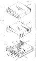
- a personal computer system embodying the present invention is there shown and generally indicated at 10 ( Figure 1).
- the computer 10 may have an associated monitor 11, keyboard 12 and printer or plotter 14.
- the computer 10 has a cover 15 formed by a decorative outer member 16 ( Figure 2) and an inner shield member 18 which cooperate with a chassis 19 in defining an enclosed, shielded volume for receiving electrically powered data processing and storage components for processing and storing digital data.
- At least certain of these components are mounted on a multilayer planar or motherboard 20 which is mounted on the chassis 19 and provides a means for electrically interconnecting the components of the computer 10 including those identified above and such other associated elements as floppy disk drives, various forms of direct access storage devices, accessory cards or boards, and the like.
- the chassis 19 has a base 22, a front panel 24, and a rear panel 25 ( Figure 2).
- the front panel 24 defines at least one open bay (and in the form illustrated, four bays) for receiving a data storage device such as a disk drive for magnetic or optical disks, a tape backup drive, or the like.
- a pair of upper bays 26, 28 and a pair of lower bays 29, 30 are provided.
- One of the upper bays 26 is adapted to receive peripheral drives of a first size (such as those known as 3.5 inch drives) while the other 28 is adapted to receive drives of a selected one of two sizes (such as 3.5 and 5.25 inch) and the lower bays are adapted to receive devices of only one size (3.5 inch).
- One fixed disc DASD is indicated at 90 in Figure 1, and capable of receiving, storing and delivering data as is generally known.
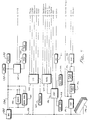
- FIG. 3 there is shown a block diagram of a first type of personal computer system illustrating the various components of the computer system such as the system 10 in accordance with the present invention, including components mounted on the planar 20 and the connection of the planar to the I/O slots and other hardware of the personal computer system.
- the system processor 32 Connected to the planar is the system processor 32 comprised of a microprocessor which is connected by a high speed CPU local bus 34 through a bus control timing unit 35 to a memory control unit 36 which is further connected to a volatile random access memory (RAM) 38.
- RAM volatile random access memory
- any appropriate microprocessor can be used, one suitable microprocessor is the 80386 which is sold by INTEL.
- system processor could be an Intel 80286 or 80486 microprocessor.
- the CPU local bus 34 (comprising data, address and control components) provides for the connection of the microprocessor 32, a math coprocessor 39, a cache controller 40, and a cache memory 41. Also coupled on the CPU local bus 34 is a buffer 42.
- the buffer 42 is itself connected to a slower speed (compared to the CPU local bus) system bus 44, also comprising address, data and control components.
- the system bus 44 extends between the buffer 42 and further buffers 51, 68.
- the system bus 44 is further connected to the bus control and timing unit 35 and a DMA unit 48.
- the DMA unit 48 is comprised of a central arbitration unit 49 and DMA controller 50.
- One buffer 51 provides an interface between the system bus 44 and an optional feature bus such as the ISA bus 52.
- Connected to the bus 52 are a plurality of I/O slots 54 for receiving ISA adapter cards which may be further connected to an I/O device or memory.
- An arbitration control bus 55 couples the DMA controller 50 and central arbitration unit 49 to the I/O slots 54 and a diskette adapter 56.
- a memory control unit 36 which is comprised of a memory controller 59, an address multiplexor 60, and a data buffer 61.
- the memory control unit 36 is further connected to a random access memory as represented by the RAM module 38.
- the memory controller 36 includes the logic for mapping addresses to and from the microprocessor 32 to particular areas of RAM 38.
- the memory controller 36 also generates a ROM select signal (ROMSEL), that is used to enable or disable ROM 64. While the microcomputer system is shown with a basic 1 megabyte RAM module, it is understood that additional memory can be interconnected as represented in Figure 3 by the optional memory modules 65 through 67.
- a latch buffer 68 is coupled between the system bus 44 and a planar I/O bus 69.
- the planar I/O bus 69 includes address, data, and control components respectively. Coupled along the planar I/O bus 69 are a variety of I/O adapters and other components such as the display adapter 70 (which is used to drive the monitor 11), a CMOS clock 72, nonvolatile CMOS RAM 74 herein after referred to as NVRAM, a RS232 adapter 76, a parallel adapter 78, a plurality of timers 80, a diskette adapter 56, an interrupt controller 84, and a read only memory 64.
- the read only memory 64 stores the BIOS control program that is used to interface between the I/O devices and the operating system of the microprocessor 32. BIOS stored in ROM 64 can be copied into RAM 38 to decrease the execution time of BIOS. ROM 64 is further responsive (via ROMSEL signal) to memory controller 36. If ROM 64 is enabled by memory controller 36, BIOS is executed out of ROM. If ROM 64 is disabled by memory controller 36, ROM is not responsive to address enquiries from the microprocessor 32 (i.e. BIOS is executed out of RAM).
- the clock 72 is used for time of day calculations and the NVRAM is used to store system configuration data. That is, the NVRAM will contain values which describe the present configuration of the system. For example, NVRAM contains information describing the capacity of a fixed disk or diskette, the type of display, the amount of memory, time, date, etc. Of particular importance, NVRAM will contain data (can be one bit) which is used by memory controller 36 to determine whether BIOS is run out of ROM or RAM and whether to reclaim RAM intended to be used by BIOS RAM. Furthermore, these data are stored in NVRAM whenever a special configuration program, such as SET Configuration, is executed. The purpose of the SET Configuration program is to store values characterizing the configuration of the system to NVRAM.
- SET Configuration program is to store values characterizing the configuration of the system to NVRAM.
- the computer has a cover indicated generally at 15 which cooperates with the chassis 19 in forming an enclosed, shielded volume for containing the above identified components of the microcomputer.
- the cover preferably is formed with an outer decorative cover member 16 which is a unitary molded component made of a moldable synthetic material and a metallic thin sheet liner 18 formed to conform to the configuration of the decorative cover member.
- the cover can be made in other known ways and the utility of this invention is not limited to enclosures of the type described.
- FIG. 4 An alternate arrangement for an ISA personal computer is shown in Figure 4, where is shown a block diagram of a personal computer system illustrating various components of an alternate arrangement for the computer system such as the system 10 in accordance with the present invention.
- FIG. 4 An alternate arrangement for an ISA personal computer is shown in Figure 4, where is shown a block diagram of a personal computer system illustrating various components of an alternate arrangement for the computer system such as the system 10 in accordance with the present invention.
- like reference characters of a one hundred order of magnitude may be used.
- the microprocessor 132 shown in Figure 4 is generally similar in function to the microprocessor 32 of Figure 3.
- the CPU 132 is connected by a high speed CPU local bus 134 to a bus interface control unit 135, to volatile random access memory (RAM) 138 here shown as Single Inline Memory Modules (SIMMs) and to BIOS ROM 164 in which is stored instructions for basic input/output operations to the CPU 132.
- RAM volatile random access memory
- BIOS ROM 164 BIOS ROM 164 in which is stored instructions for basic input/output operations to the CPU 132.
- the BIOS ROM 164 includes the BIOS that is used to interface between the I/O devices and the operating system of the microprocessor 132. Instructions stored in ROM 164 can be copied into RAM 138 to decrease the execution time of BIOS.
- the CPU local bus 134 (comprising data, address and control components) also provides for the connection of the microprocessor 132 with a math coprocessor 139 and a DASD controller 185.
- the DASD controller 185 may, as is known to persons skilled in the arts of computer design and operation, be connected or connectable with Read Only Memory (ROM) 186, RAM 188, and suitable external devices of a variety of types as facilitated by the I/O connection indicated to the right in the Figure.
- ROM Read Only Memory
- the bus interface controller (BIC) 135 couples the CPU local bus 134 with an I/O bus 152.
- the BIC 135 is coupled with an optional feature bus such as an ISA bus having a plurality of I/O slots for receiving adapter cards 190 which may be further connected to an I/O device or memory (not shown).
- the I/O bus 152 includes address, data, and control components.
- Coupled along the I/O bus 152 are a variety of I/O components such as a video signal processor 191 which is associated with video RAM (VRAM) for storing graphic information (indicated at 192) and for storing image information (indicated at 194).
- Video signals exchanged with the processor 191 may be passed through a Digital to Analog Converter (DAC) 195 to a monitor or other display device.
- DAC Digital to Analog Converter
- the I/O bus 152 is also coupled with a Digital Signal Processor (DSP) 196 which has associated instruction RAM 198 and data RAM 199 available to store software instructions for the processing of signals by the DSP 196 and data involved in such processing.
- DSP Digital Signal Processor
- the DSP 196 provides for processing of audio inputs and outputs by the provision of an audio controller 200, and for handling of other signals by provision of an analog interface controller 201.
- the I/O bus 152 is coupled with a input/output controller 202 with associated Electrical Erasable Programmable Read Only Memory (EEPROM) 204 by which inputs and outputs are exchanged with conventional peripherals including floppy disk drives, a printer or plotter 14, keyboard 12, a mouse or pointing device, and by means of a serial port.
- EEPROM Electrical Erasable Programmable Read Only Memory
- the DASD used may have a number of cylinders and heads which fall within the Interrupt 13 design expectations. That is, the number of cylinders may be 1024 or less and the number of heads may be 256 or less. In that event, then no difficulty is encountered in the normal operation of the personal computer system resulting in the interrogation of the DASD as to its characteristics, storing of that information as part of the system configuration, and operation of the system during normal use as is well known in the prior art.
- CHS addressing which is within the Interrupt 13 design expectations is used to address an ATA DASD which has a number of cylinders in excess of 1024, sixteen heads, and a storage capacity for digital data which exceeds five hundred twenty eight million four hundred eighty two thousand three hundred four bytes of digital data. This is accomplished, in accordance with this invention, by effecting a translation between two frames of reference for CHS addressing.
- a first frame of reference for CHS addressing which has a number of cylinders which exceeds one thousand twenty four and a number of heads which is reflective of the actual number of heads found in the drive to be attached and addressed. As has been expressed, that number is typically sixteen heads in drives of the type commonly encountered at the time this invention has been embodied into physical, operating personal computer systems. However, the number of heads may be any predetermined number other than sixteen which may be selected and used by a DASD designer.
- the first frame of reference corresponds to the physical characteristics of the DASD to be used.
- a second frame of reference for CHS addressing is also established, with the second frame having a number of cylinders and heads which fits with the Interrupt 13 design assumptions. That is, the second frame of reference has no more than 1024 cylinders and no more than 256 heads.
- the present invention contemplates that CHS addressing data exchanged between the two frames of reference is translated to enable the exchange of data with the full storage capacity of the attached DASD. This translation is accomplished by establishing a particular relationship between the addressing in the first frame of reference and that in the second frame of reference.
- the discussion which follows will address the manner of establishing the two frames of reference and accomplishing the translation between them.
- the establishing and translating is contemplated as being useful with a variety of forms of DASD control which can be encountered. More specifically, the invention to be described has utility with DASD which is controlled through a controller card mounted in an I/O bus connector; with DASD which is of the IDE type; and with DASD which is addressed directly under the control of the system CPU 32, 132.
- DASD which is controlled through a controller card mounted in an I/O bus connector
- DASD which is of the IDE type
- DASD which is addressed directly under the control of the system CPU 32, 132.
- the addressing microprocessor is commonly located on the card.
- the addressing microprocessor is commonly integrated into the DASD.
- the microprocessor is the system CPU.
- a control program which is stored accessibly to the microprocessor, loaded into the microprocessor, and which cooperates with the microprocessor in accomplishing the addressing. That control program often can be, and is here, referred to as a basic input/output system, or a portion of such a system, also known as a BIOS.
- BIOS for a personal computer system can comprise the primary BIOS referred to above in the discussion of the system organization illustrated in Figures 3 and 4; or an option card BIOS portion such as may be stored on an option card such as a DASD controller; or a device BIOS such as may be stored as a part of an IDE DASD; or a portion of the primary BIOS as earlier described.
- the present invention contemplates that the control program mentioned hereinafter can be any of these various types.
- a system as contemplated by this invention has a rotating media direct access storage device (DASD) 90 for receiving, storing and delivering digital data.
- the DASD has a first predetermined number of cylinders and a second predetermined number of heads, each of the cylinders being divided into a third predetermined number of sectors.
- the heads exchange digital data with the sectors of the cylinders, writing to or reading from the sectors as directed by CHS addressing signals.
- the cylinders, heads, and sectors together define a storage capacity for the DASD in excess of five hundred twenty eight million four hundred eighty two thousand three hundred four bytes of digital data.
- the system has a microprocessor for processing digital data, with the microprocessor controlling the exchange of digital data with the DASD using cylinder-head-sector storage address data.
- the system also has a control program accessible to the microprocessor for controlling the flow of digital data to and from the DASD.
- the microprocessor accesses the control program, loads the control program and, operating under the control of said control program, performs a sequence of operations which enable the exchange of data with the full storage capacity of the DASD.
- the operations performed include establishing the first and second frames of reference mentioned above and then translating between them.
- the system determines a conversion factor to be applied, following steps as shown in Figure 5.
- Those steps comprise interrogating as to the number of cylinders provided in the DASD, then determining whether the number of cylinders is greater than sixteen thousand three hundred eighty four. The latter number is the maximum which can be addressed in the specific implementation here described, and may vary should the implementation vary from what is here described in detail. If the number is greater, then the number sixteen thousand three hundred eighty four is used for the next following steps. If not, then the number reported is used.
- the next step is to set a register to be used to store the conversion factor to a zero registered value.
- the process then returns to interrogating as to the number of cylinders identified as the quotient of the preceding division, dividing the quotient number of cylinders by two if greater than one thousand twenty four, incrementing the conversion factor register by one, and repeating the division/incrementing until the quotient number of cylinders is less than one thousand twenty four.
- the count stored in the register is the conversion factor (herein also identified as "N") to be later applied.
- the conversion factor may be stored as part of the system configuration data held in NVRAM.
- the frames of reference mentioned above may be set.
- One such frame is set by a procedure to get the drive parameters of the DASD, as illustrated in Figure 6.
- cylinder and head values are retrieved from the DASD or from previously stored values by interrogation.
- the cylinder number is then converted using the conversion factor, by dividing the cylinder number by two (the divisor in the previously described process of determining the conversion factor) raised to the power of the conversion factor.
- Another way to explain this conversion is that the cylinder number is shifted right by the conversion factor.
- Converted Cylinder Cylinder/2 N
- a DASD has in integer number of cylinders and cannot have fractional cylinders. Any fractional cylinder which would otherwise appear to have been created in conversion is discarded. That is, a drive with two thousand one cylinders and sixteen heads will be reported as having one thousand cylinders and thirty two heads. The half of a BIOS cylinder is "lost". If such a DASD is addressed through a BIOS using the Interrupt 13 design restraints at cylinder 0 head 20, the physical DASD is accessed at cylinder 1 head 4.
- a system is provided with a DASD which has two thousand cylinders and sixteen heads for a total storage capability of ten billion, one hundred four million, one hundred ninety two thousand bytes of digital data (2000 X 16 X 63 X 512).
- the conversion factor becomes one (one division of 2000 by 2 leaves a quotient of 1000, which is less than 1024).
- the second reference frame is established by the DASD itself, as having a range of more than one thousand twenty four cylinders and a range of up to a predetermined number of heads, namely the number provided on the physical drive. In the instance given above (as is the case for most ATA DASD) the number is sixteen.
- Translation between the two reference frames occurs as illustrated in Figure 7, through the operation of the control program with the microprocessor as described above. More particularly, translation of storage address digital data exchanged between the first and second reference frames to enable the exchange of data with the full storage capacity of said DASD is accomplished using the number (N) of times dividing of the number of cylinders by two was repeated.
- N the number of times dividing of the number of cylinders by two was repeated.
- the first inquiry is of the stored data, to determine whether the stored conversion factor is other than zero. If it is zero, then no conversion is required and CHS addressing proceeds as contemplated by the original Interrupt 13 design. If it is greater than zero, then the cylinder number in the drive command is multiplied by two raised to the power of the conversion factor, N.
- Translated Cylinder Converted Cylinder X 2 N
- the converted head number is then divided by the number of heads physically present in the DASD, and the remainder after such division is identified as the translated head number.
- the quotient of this division is then logically "OR"ed with the translated cylinder number and identified as the addressed cylinder number.
- such determination of a conversion factor, conversion and translation can occur either as a function of the system BIOS in cooperation with the system CPU; as a function of a controller card BIOS in cooperation with a controller microprocessor; or as a function of an IDE BIOS in cooperation with an IDE microprocessor.
- the effect of the translation is the same: a CHS address in a first frame of reference which meets the restraints of Interrupt 13 design in the ISA BIOS is translated to a CHS address in a second frame of reference which meets the physical characteristics of a DASD which is otherwise outside the restraints of Interrupt 13 design in the ISA BIOS.
Landscapes
- Engineering & Computer Science (AREA)
- Theoretical Computer Science (AREA)
- Human Computer Interaction (AREA)
- Physics & Mathematics (AREA)
- General Engineering & Computer Science (AREA)
- General Physics & Mathematics (AREA)
- Memory System Of A Hierarchy Structure (AREA)
- Signal Processing For Digital Recording And Reproducing (AREA)
- Information Retrieval, Db Structures And Fs Structures Therefor (AREA)
- Magnetic Record Carriers (AREA)
- Diaphragms For Electromechanical Transducers (AREA)
- Crystals, And After-Treatments Of Crystals (AREA)
- Compression, Expansion, Code Conversion, And Decoders (AREA)
- Studio Devices (AREA)
- Advance Control (AREA)
- Memory System (AREA)
- Liquid Crystal Display Device Control (AREA)
- Saccharide Compounds (AREA)
- Machine Translation (AREA)
- Hardware Redundancy (AREA)
Applications Claiming Priority (3)
| Application Number | Priority Date | Filing Date | Title |
|---|---|---|---|
| US224846 | 1994-04-07 | ||
| US08/224,846 US5805857A (en) | 1994-04-07 | 1994-04-07 | DASD capacity in excess of 528 megabytes apparatus and method for personal computers |
| PCT/EP1994/004314 WO1995027937A1 (en) | 1994-04-07 | 1994-12-27 | Dasd capacity in excess of 528 megabytes apparatus and method for personal computers |
Publications (2)
| Publication Number | Publication Date |
|---|---|
| EP0754319A1 EP0754319A1 (en) | 1997-01-22 |
| EP0754319B1 true EP0754319B1 (en) | 1999-11-24 |
Family
ID=22842481
Family Applications (1)
| Application Number | Title | Priority Date | Filing Date |
|---|---|---|---|
| EP95905593A Expired - Lifetime EP0754319B1 (en) | 1994-04-07 | 1994-12-27 | Dasd capacity in excess of 528 megabytes apparatus and method for personal computers |
Country Status (17)
| Country | Link |
|---|---|
| US (1) | US5805857A (pt) |
| EP (1) | EP0754319B1 (pt) |
| JP (1) | JP2996889B2 (pt) |
| KR (1) | KR0146663B1 (pt) |
| CN (1) | CN1096029C (pt) |
| AT (1) | ATE186997T1 (pt) |
| BR (1) | BR9501455A (pt) |
| CA (1) | CA2145924C (pt) |
| CZ (1) | CZ9602846A3 (pt) |
| DE (1) | DE69421829T2 (pt) |
| ES (1) | ES2140653T3 (pt) |
| HU (1) | HU219931B (pt) |
| MY (1) | MY115158A (pt) |
| PL (1) | PL176972B1 (pt) |
| RU (1) | RU2155369C2 (pt) |
| SG (1) | SG50425A1 (pt) |
| WO (1) | WO1995027937A1 (pt) |
Families Citing this family (8)
| Publication number | Priority date | Publication date | Assignee | Title |
|---|---|---|---|---|
| US6304636B1 (en) | 1997-12-23 | 2001-10-16 | At&T Corp. | Forwarding voice messages to a called party using electronic mail |
| US6397381B1 (en) * | 1998-09-21 | 2002-05-28 | Microsoft Corporation | System and method for repairing a damaged application program |
| US8225002B2 (en) | 1999-01-22 | 2012-07-17 | Network Disk, Inc. | Data storage and data sharing in a network of heterogeneous computers |
| US6549988B1 (en) | 1999-01-22 | 2003-04-15 | Ilya Gertner | Data storage system comprising a network of PCs and method using same |
| US6661785B1 (en) * | 1999-10-12 | 2003-12-09 | Bellsouth Intellectual Property Corporation | Method and apparatus for providing internet call waiting with voice over internet protocol |
| US20090240903A1 (en) * | 2008-03-20 | 2009-09-24 | Dell Products L.P. | Methods and Apparatus for Translating a System Address |
| CN102419694A (zh) * | 2010-09-27 | 2012-04-18 | 智微科技股份有限公司 | 存取储存装置的方法与电子系统 |
| US9142271B1 (en) * | 2014-06-24 | 2015-09-22 | Intel Corporation | Reference architecture in a cross-point memory |
Family Cites Families (14)
| Publication number | Priority date | Publication date | Assignee | Title |
|---|---|---|---|---|
| US4223390A (en) * | 1976-02-02 | 1980-09-16 | International Business Machines Corporation | System and method for attaching magnetic storage devices having dissimilar track capacities and recording formats |
| JPS5362945A (en) * | 1976-11-17 | 1978-06-05 | Toshiba Corp | Disc address system |
| US4467421A (en) * | 1979-10-18 | 1984-08-21 | Storage Technology Corporation | Virtual storage system and method |
| US4583194A (en) * | 1981-12-23 | 1986-04-15 | Pitney Bowes Inc. | Fixed disk controller for use in a word processing system |
| US4591997A (en) * | 1983-11-28 | 1986-05-27 | Polaroid Corporation | Method of storing and printing image with non-reentrant basic disk operating system |
| US5043885A (en) * | 1989-08-08 | 1991-08-27 | International Business Machines Corporation | Data cache using dynamic frequency based replacement and boundary criteria |
| US5072378A (en) * | 1989-12-18 | 1991-12-10 | Storage Technology Corporation | Direct access storage device with independently stored parity |
| US5018095A (en) * | 1990-02-15 | 1991-05-21 | Seagate Technology, Inc. | Universal disk drive type emulation for IBM PC-AT computers |
| US5247633A (en) * | 1990-02-28 | 1993-09-21 | Seagate Technology, Inc. | Configuration of high capacity disk drives with embedded ibm pc-at type computer |
| US5263145A (en) * | 1990-05-24 | 1993-11-16 | International Business Machines Corporation | Method and means for accessing DASD arrays with tuned data transfer rate and concurrency |
| DE69127864T2 (de) * | 1990-07-19 | 1998-03-26 | Ibm | Personalcomputer mit Laufwerk-Identifizierung |
| US5280602A (en) * | 1991-07-31 | 1994-01-18 | Silicon Systems, Inc. | Task file with automatic update of task file registers |
| US5309451A (en) * | 1992-08-12 | 1994-05-03 | Digital Equipment Corporation | Data and parity prefetching for redundant arrays of disk drives |
| US5465338A (en) * | 1993-08-24 | 1995-11-07 | Conner Peripherals, Inc. | Disk drive system interface architecture employing state machines |
-
1994
- 1994-04-07 US US08/224,846 patent/US5805857A/en not_active Expired - Fee Related
- 1994-10-31 MY MYPI94002882A patent/MY115158A/en unknown
- 1994-10-31 CN CN94113735A patent/CN1096029C/zh not_active Expired - Fee Related
- 1994-12-27 WO PCT/EP1994/004314 patent/WO1995027937A1/en not_active Application Discontinuation
- 1994-12-27 CZ CZ19962846A patent/CZ9602846A3/cs unknown
- 1994-12-27 EP EP95905593A patent/EP0754319B1/en not_active Expired - Lifetime
- 1994-12-27 DE DE69421829T patent/DE69421829T2/de not_active Expired - Fee Related
- 1994-12-27 PL PL94316564A patent/PL176972B1/pl unknown
- 1994-12-27 RU RU96120087/09A patent/RU2155369C2/ru active
- 1994-12-27 AT AT95905593T patent/ATE186997T1/de not_active IP Right Cessation
- 1994-12-27 HU HU9602593A patent/HU219931B/hu not_active IP Right Cessation
- 1994-12-27 SG SG1996001135A patent/SG50425A1/en unknown
- 1994-12-27 ES ES95905593T patent/ES2140653T3/es not_active Expired - Lifetime
- 1994-12-30 KR KR1019940040060A patent/KR0146663B1/ko not_active IP Right Cessation
-
1995
- 1995-01-27 JP JP7011809A patent/JP2996889B2/ja not_active Expired - Fee Related
- 1995-03-30 CA CA002145924A patent/CA2145924C/en not_active Expired - Fee Related
- 1995-04-05 BR BR9501455A patent/BR9501455A/pt not_active IP Right Cessation
Also Published As
| Publication number | Publication date |
|---|---|
| ATE186997T1 (de) | 1999-12-15 |
| EP0754319A1 (en) | 1997-01-22 |
| US5805857A (en) | 1998-09-08 |
| PL316564A1 (en) | 1997-01-20 |
| JPH07281837A (ja) | 1995-10-27 |
| DE69421829T2 (de) | 2000-05-25 |
| RU2155369C2 (ru) | 2000-08-27 |
| CN1115894A (zh) | 1996-01-31 |
| WO1995027937A1 (en) | 1995-10-19 |
| HU9602593D0 (en) | 1996-11-28 |
| BR9501455A (pt) | 1995-11-07 |
| HU219931B (hu) | 2001-09-28 |
| DE69421829D1 (de) | 1999-12-30 |
| JP2996889B2 (ja) | 2000-01-11 |
| CA2145924A1 (en) | 1995-10-08 |
| CZ9602846A3 (cs) | 2002-06-12 |
| HUT75817A (en) | 1997-05-28 |
| KR950029935A (ko) | 1995-11-24 |
| SG50425A1 (en) | 1998-07-20 |
| CA2145924C (en) | 2001-01-30 |
| PL176972B1 (pl) | 1999-08-31 |
| KR0146663B1 (ko) | 1998-09-15 |
| ES2140653T3 (es) | 2000-03-01 |
| CN1096029C (zh) | 2002-12-11 |
| MY115158A (en) | 2003-04-30 |
Similar Documents
| Publication | Publication Date | Title |
|---|---|---|
| CA2099025C (en) | Personal computer with programmable threshold fifo registers for data transfer | |
| US5371861A (en) | Personal computer with small computer system interface (SCSI) data flow storage controller capable of storing and processing multiple command descriptions ("threads") | |
| US5465332A (en) | Selectable 8/16 bit DMA channels for "ISA" bus | |
| US5265255A (en) | Personal computer system with interrupt controller | |
| US5214762A (en) | Disk drive activity indicator | |
| US5544334A (en) | Micro channel bus computer system with IDE hard drive interface | |
| US5142626A (en) | Personal computer with removable media identification | |
| US5471585A (en) | Personal computer system with input/output controller having serial/parallel ports and a feedback line indicating readiness of the ports | |
| EP0754319B1 (en) | Dasd capacity in excess of 528 megabytes apparatus and method for personal computers | |
| US5440693A (en) | Personal computer with drive identification | |
| CA2065999A1 (en) | Personal computer, memory element and method | |
| CA2065991C (en) | Personal computer data transfer control | |
| US5293590A (en) | Personal computer with interface controller | |
| US5550991A (en) | Personal computer system having high speed local processor bus and storage controller with FIFO memory coupled directly thereto | |
| CA2066001C (en) | Personal computer memory write control | |
| EP0517415A1 (en) | Personal computer with enhanced memory access and method | |
| EP0661638A1 (en) | Method and apparatus for transferring data in a computer | |
| EP0516289A2 (en) | Computer system and method of operating the computer system | |
| IE80597B1 (en) | Personal computer with drive identification | |
| JPH05128055A (ja) | 代替システム制御装置用の装備を有したパーソナル・コンピユータ・システム |
Legal Events
| Date | Code | Title | Description |
|---|---|---|---|
| PUAI | Public reference made under article 153(3) epc to a published international application that has entered the european phase |
Free format text: ORIGINAL CODE: 0009012 |
|
| 17P | Request for examination filed |
Effective date: 19960729 |
|
| AK | Designated contracting states |
Kind code of ref document: A1 Designated state(s): AT BE CH DE ES FR GB IT LI NL SE |
|
| RAP1 | Party data changed (applicant data changed or rights of an application transferred) |
Owner name: INTERNATIONAL BUSINESS MACHINES CORPORATION |
|
| 17Q | First examination report despatched |
Effective date: 19970807 |
|
| GRAG | Despatch of communication of intention to grant |
Free format text: ORIGINAL CODE: EPIDOS AGRA |
|
| GRAG | Despatch of communication of intention to grant |
Free format text: ORIGINAL CODE: EPIDOS AGRA |
|
| GRAH | Despatch of communication of intention to grant a patent |
Free format text: ORIGINAL CODE: EPIDOS IGRA |
|
| GRAH | Despatch of communication of intention to grant a patent |
Free format text: ORIGINAL CODE: EPIDOS IGRA |
|
| GRAA | (expected) grant |
Free format text: ORIGINAL CODE: 0009210 |
|
| AK | Designated contracting states |
Kind code of ref document: B1 Designated state(s): AT BE CH DE ES FR GB IT LI NL SE |
|
| REF | Corresponds to: |
Ref document number: 186997 Country of ref document: AT Date of ref document: 19991215 Kind code of ref document: T |
|
| REG | Reference to a national code |
Ref country code: CH Ref legal event code: NV Representative=s name: DIPL.-ING. CHRISTIAN HEUSCH C/O INTERNATIONAL BUSI Ref country code: CH Ref legal event code: EP |
|
| PGFP | Annual fee paid to national office [announced via postgrant information from national office to epo] |
Ref country code: FR Payment date: 19991217 Year of fee payment: 6 |
|
| PGFP | Annual fee paid to national office [announced via postgrant information from national office to epo] |
Ref country code: BE Payment date: 19991222 Year of fee payment: 6 |
|
| REF | Corresponds to: |
Ref document number: 69421829 Country of ref document: DE Date of ref document: 19991230 |
|
| ITF | It: translation for a ep patent filed |
Owner name: BRAVI ALFREDO DR. |
|
| REG | Reference to a national code |
Ref country code: ES Ref legal event code: FG2A Ref document number: 2140653 Country of ref document: ES Kind code of ref document: T3 |
|
| ET | Fr: translation filed | ||
| PGFP | Annual fee paid to national office [announced via postgrant information from national office to epo] |
Ref country code: CH Payment date: 20000327 Year of fee payment: 6 |
|
| PLBE | No opposition filed within time limit |
Free format text: ORIGINAL CODE: 0009261 |
|
| STAA | Information on the status of an ep patent application or granted ep patent |
Free format text: STATUS: NO OPPOSITION FILED WITHIN TIME LIMIT |
|
| 26N | No opposition filed | ||
| PG25 | Lapsed in a contracting state [announced via postgrant information from national office to epo] |
Ref country code: LI Free format text: LAPSE BECAUSE OF NON-PAYMENT OF DUE FEES Effective date: 20001231 Ref country code: CH Free format text: LAPSE BECAUSE OF NON-PAYMENT OF DUE FEES Effective date: 20001231 Ref country code: BE Free format text: LAPSE BECAUSE OF NON-PAYMENT OF DUE FEES Effective date: 20001231 |
|
| BERE | Be: lapsed |
Owner name: INTERNATIONAL BUSINESS MACHINES CORP. Effective date: 20001231 |
|
| REG | Reference to a national code |
Ref country code: CH Ref legal event code: PL |
|
| PGFP | Annual fee paid to national office [announced via postgrant information from national office to epo] |
Ref country code: SE Payment date: 20011121 Year of fee payment: 8 |
|
| PGFP | Annual fee paid to national office [announced via postgrant information from national office to epo] |
Ref country code: ES Payment date: 20011214 Year of fee payment: 8 |
|
| PGFP | Annual fee paid to national office [announced via postgrant information from national office to epo] |
Ref country code: AT Payment date: 20011227 Year of fee payment: 8 |
|
| PGFP | Annual fee paid to national office [announced via postgrant information from national office to epo] |
Ref country code: NL Payment date: 20011231 Year of fee payment: 8 |
|
| REG | Reference to a national code |
Ref country code: GB Ref legal event code: IF02 |
|
| PG25 | Lapsed in a contracting state [announced via postgrant information from national office to epo] |
Ref country code: FR Free format text: LAPSE BECAUSE OF NON-PAYMENT OF DUE FEES Effective date: 20020228 |
|
| PG25 | Lapsed in a contracting state [announced via postgrant information from national office to epo] |
Ref country code: AT Free format text: LAPSE BECAUSE OF NON-PAYMENT OF DUE FEES Effective date: 20021227 |
|
| PG25 | Lapsed in a contracting state [announced via postgrant information from national office to epo] |
Ref country code: SE Free format text: LAPSE BECAUSE OF NON-PAYMENT OF DUE FEES Effective date: 20021228 Ref country code: ES Free format text: LAPSE BECAUSE OF NON-PAYMENT OF DUE FEES Effective date: 20021228 |
|
| PG25 | Lapsed in a contracting state [announced via postgrant information from national office to epo] |
Ref country code: NL Free format text: LAPSE BECAUSE OF NON-PAYMENT OF DUE FEES Effective date: 20030701 |
|
| EUG | Se: european patent has lapsed | ||
| NLV4 | Nl: lapsed or anulled due to non-payment of the annual fee |
Effective date: 20030701 |
|
| REG | Reference to a national code |
Ref country code: ES Ref legal event code: FD2A Effective date: 20021228 |
|
| PGFP | Annual fee paid to national office [announced via postgrant information from national office to epo] |
Ref country code: DE Payment date: 20041124 Year of fee payment: 11 |
|
| PG25 | Lapsed in a contracting state [announced via postgrant information from national office to epo] |
Ref country code: IT Free format text: LAPSE BECAUSE OF NON-PAYMENT OF DUE FEES Effective date: 20051227 |
|
| PGFP | Annual fee paid to national office [announced via postgrant information from national office to epo] |
Ref country code: GB Payment date: 20060125 Year of fee payment: 12 |
|
| PG25 | Lapsed in a contracting state [announced via postgrant information from national office to epo] |
Ref country code: DE Free format text: LAPSE BECAUSE OF NON-PAYMENT OF DUE FEES Effective date: 20060701 |
|
| REG | Reference to a national code |
Ref country code: GB Ref legal event code: 732E |
|
| GBPC | Gb: european patent ceased through non-payment of renewal fee |
Effective date: 20061227 |
|
| PG25 | Lapsed in a contracting state [announced via postgrant information from national office to epo] |
Ref country code: GB Free format text: LAPSE BECAUSE OF NON-PAYMENT OF DUE FEES Effective date: 20061227 |
|
| PG25 | Lapsed in a contracting state [announced via postgrant information from national office to epo] |
Ref country code: FR Free format text: LAPSE BECAUSE OF NON-PAYMENT OF DUE FEES Effective date: 20001231 |