EP0754264B1 - Verfahren und wasserfahrzeug zur bearbeitung eines unterwasserbodens - Google Patents
Verfahren und wasserfahrzeug zur bearbeitung eines unterwasserbodens Download PDFInfo
- Publication number
- EP0754264B1 EP0754264B1 EP95913942A EP95913942A EP0754264B1 EP 0754264 B1 EP0754264 B1 EP 0754264B1 EP 95913942 A EP95913942 A EP 95913942A EP 95913942 A EP95913942 A EP 95913942A EP 0754264 B1 EP0754264 B1 EP 0754264B1
- Authority
- EP
- European Patent Office
- Prior art keywords
- bed
- nozzle
- water
- vessel
- pressure
- Prior art date
- Legal status (The legal status is an assumption and is not a legal conclusion. Google has not performed a legal analysis and makes no representation as to the accuracy of the status listed.)
- Expired - Lifetime
Links
- 238000000034 method Methods 0.000 title claims abstract description 26
- XLYOFNOQVPJJNP-UHFFFAOYSA-N water Substances O XLYOFNOQVPJJNP-UHFFFAOYSA-N 0.000 claims abstract description 58
- 239000000463 material Substances 0.000 claims description 26
- 239000007921 spray Substances 0.000 claims description 7
- 239000002245 particle Substances 0.000 claims description 6
- 238000010790 dilution Methods 0.000 claims description 4
- 239000012895 dilution Substances 0.000 claims description 4
- 230000000694 effects Effects 0.000 description 2
- 238000005086 pumping Methods 0.000 description 2
- 230000009286 beneficial effect Effects 0.000 description 1
- 238000007596 consolidation process Methods 0.000 description 1
- 238000007865 diluting Methods 0.000 description 1
- 238000005243 fluidization Methods 0.000 description 1
- 238000009434 installation Methods 0.000 description 1
- 239000000203 mixture Substances 0.000 description 1
- 230000035515 penetration Effects 0.000 description 1
- 230000000717 retained effect Effects 0.000 description 1
- 239000004576 sand Substances 0.000 description 1
- 239000007779 soft material Substances 0.000 description 1
- 239000002689 soil Substances 0.000 description 1
- 238000005507 spraying Methods 0.000 description 1
- 238000005406 washing Methods 0.000 description 1
- 230000003313 weakening effect Effects 0.000 description 1
Images
Classifications
-
- E—FIXED CONSTRUCTIONS
- E02—HYDRAULIC ENGINEERING; FOUNDATIONS; SOIL SHIFTING
- E02F—DREDGING; SOIL-SHIFTING
- E02F3/00—Dredgers; Soil-shifting machines
- E02F3/04—Dredgers; Soil-shifting machines mechanically-driven
- E02F3/88—Dredgers; Soil-shifting machines mechanically-driven with arrangements acting by a sucking or forcing effect, e.g. suction dredgers
- E02F3/90—Component parts, e.g. arrangement or adaptation of pumps
- E02F3/92—Digging elements, e.g. suction heads
- E02F3/9206—Digging devices using blowing effect only, like jets or propellers
-
- E—FIXED CONSTRUCTIONS
- E02—HYDRAULIC ENGINEERING; FOUNDATIONS; SOIL SHIFTING
- E02F—DREDGING; SOIL-SHIFTING
- E02F3/00—Dredgers; Soil-shifting machines
- E02F3/04—Dredgers; Soil-shifting machines mechanically-driven
- E02F3/88—Dredgers; Soil-shifting machines mechanically-driven with arrangements acting by a sucking or forcing effect, e.g. suction dredgers
- E02F3/90—Component parts, e.g. arrangement or adaptation of pumps
- E02F3/905—Manipulating or supporting suction pipes or ladders; Mechanical supports or floaters therefor; pipe joints for suction pipes
-
- E—FIXED CONSTRUCTIONS
- E02—HYDRAULIC ENGINEERING; FOUNDATIONS; SOIL SHIFTING
- E02F—DREDGING; SOIL-SHIFTING
- E02F5/00—Dredgers or soil-shifting machines for special purposes
- E02F5/02—Dredgers or soil-shifting machines for special purposes for digging trenches or ditches
- E02F5/10—Dredgers or soil-shifting machines for special purposes for digging trenches or ditches with arrangements for reinforcing trenches or ditches; with arrangements for making or assembling conduits or for laying conduits or cables
- E02F5/104—Dredgers or soil-shifting machines for special purposes for digging trenches or ditches with arrangements for reinforcing trenches or ditches; with arrangements for making or assembling conduits or for laying conduits or cables for burying conduits or cables in trenches under water
- E02F5/107—Dredgers or soil-shifting machines for special purposes for digging trenches or ditches with arrangements for reinforcing trenches or ditches; with arrangements for making or assembling conduits or for laying conduits or cables for burying conduits or cables in trenches under water using blowing-effect devices, e.g. jets
-
- E—FIXED CONSTRUCTIONS
- E02—HYDRAULIC ENGINEERING; FOUNDATIONS; SOIL SHIFTING
- E02F—DREDGING; SOIL-SHIFTING
- E02F5/00—Dredgers or soil-shifting machines for special purposes
- E02F5/02—Dredgers or soil-shifting machines for special purposes for digging trenches or ditches
- E02F5/10—Dredgers or soil-shifting machines for special purposes for digging trenches or ditches with arrangements for reinforcing trenches or ditches; with arrangements for making or assembling conduits or for laying conduits or cables
- E02F5/104—Dredgers or soil-shifting machines for special purposes for digging trenches or ditches with arrangements for reinforcing trenches or ditches; with arrangements for making or assembling conduits or for laying conduits or cables for burying conduits or cables in trenches under water
- E02F5/108—Dredgers or soil-shifting machines for special purposes for digging trenches or ditches with arrangements for reinforcing trenches or ditches; with arrangements for making or assembling conduits or for laying conduits or cables for burying conduits or cables in trenches under water using suction-effect devices
Definitions
- the invention is related to a method for treating the bed of a body of water by means of a directed water jet, which water jet is moved over the bed in accordance with an elongated path, wherein water is pumped under pressure on board a vessel and is then discharged, via a pressure line connected to said vessel, a small distance above, and directed towards the bed.
- Such a method is known from EP-A-548707, and is applied for increasing to the water depth of a body of water by weakening the bottom material, treating it by a water jet and removing it.
- a flow line is applied, which has jets by means of which a jacket of water at a pressure of about 0.6 MPa (6 bar) pressure can be generated for washing away the bottom material.
- This jacket flow is additional to a high pressure flow by means of which the hard bottom material is destroyed.
- the present invention aims at providing a method for providing a trench in the bottom of a body of water consisting of a soft material, such as sand.
- a soft material such as sand.
- Such bottom material has a very low cohesion in comparison to a hard rocky or stony bottom.
- This aim is achieved in that the water is pumped at an overpressure between 1 KPa and 2 MPa, at a flow rate of 0.25 to 20.0 cubic metres per second.
- the bottom material is not removed from the bottom so as to increase the general depth thereof, but is instead merely blown away to the side so as to obtain a trench.
- any equipment in particular that for generating the water jet, can be installed on board the vessel itself. This means that that part of the installation which remains underwater can remain relatively simple, which is beneficial for the reliability and also results in lower costs.
- the water can be pumped preferably at an overpressure between 1 KPa and 0.8 MPa.
- various results can be obtained by means of such pressures.
- the distance of the nozzle to the bed is equal to maximally 10 times the diameter of the water jet defined by the nozzle or the envelope of several jets defined by the nozzle.
- said distance to the bed is equal to 6 times the diameter of the water jet defined by the nozzle or of the envlope of several jets defined by the nozzle.
- the pressure and the flow rate of the water jet must be chosen sufficiently high that the bed material is completely fluidised and sprayed away.
- the water is fed into the bed material in such a way that the particle skeleton thereof partially loses its cohesion and/or strength (dilution). In this case, complete fluidisation does not occur and the bed material retains a certain cohesion and/or strength.
- This variant of the method according to the invention can be used when burying a cable or pipeline laid in or on the bed. In this case, the pressure and the flow rate of the water jet are so chosen that the cohesion and/or strength of the particle skeleton of the bed material is reduced down to such a depth that the pipeline or cable sinks into the bed under the influence of its own weight.
- a cable or pipeline to be buried can also be laid sometime after dilution of the bed material.
- the interval between the treatment of the bed material and laying of a cable or pipeline depends on the consolidation time of the bed material.
- the invention also relates to a vessel for carrying out the method described above.
- a vessel of this type has a pressure line which has a spray nozzle, as well as means for holding the pressure line against the force of reaction of the water jet discharged from the spray nozzle, wherein the nozzle has a diameter of 0.1 to 5.0 metres in size.
- ballast means can also be provided.
- dynamic positioning means for holding the pressure line in position.
- vessels can be specially developed vessels; advantageously, however, a hopper suction dredger can be used, comprising a well in addition to at least one line which can be played out down to the bed of a body of water, pressure means being provided which are connected to the end of the line which is connected to the vessel.
- the hopper suction dredger is not used to exert a suction effect but to exert a spray effect.
- a hopper suction dredger of this type comprises suction means for drawing up bed material under suction via the line.
- switching means are now provided for connecting the pressure means or the suction means to the line, as desired.
- the nozzle can have a diameter preferably 0.2 to 1.0 metre, in size.
- the end of the nozzle can terminate in a multiplicity of smaller nozzles, which are of rectangular shape and the individual cross-sectional surface area of which is from 0.005 to 1.0 m 2 in size.
- the small nozzles can also have a circular shape, in which case the diameter of the individual nozzles is from 0.1 to 1.0 metre in size.
- the water jet can be metered easily over, for example, the circumference of the pipeline or cable.
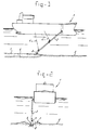
- Figure 1 shows a side view of a vessel of this type.
- Figure 2 shows a front view
- the vessel which is indicated in its entirety by 1, is constructed as a hopper suction dredger, which is provided with a line 2.
- a nozzle 3 is fitted at the end of the line 2; the line 2 itself can be paid out in an known manner, by means of cables 4 and 4', to just above the bed 5 of a body of water.
- Pumping means for pumping water via the line 2 to nozzle 3 are installed on board the hopper suction dredger in a manner which is not shown in more detail.
- a trench 6 is flushed out in the bed by the discharge of a water jet from the nozzle 3.
- the bed material which is sprayed away partly collects in the banking 7 alongside the trench 6. With this procedure, the bottom of the trench can be diluted.
- the area of the bed material which is diluted is indicated by 8 in Figure 2. The cohesion and/or strength is partly retained, but has become so low that a pipeline or cable which has already been laid is able to sink into the bed.
- Ballast means or dynamic positioning means can be provided in the vicinity of the nozzle 3 to hold the line 2 in place against the force of reaction of the water jet 3.
Landscapes
- Engineering & Computer Science (AREA)
- Mechanical Engineering (AREA)
- Mining & Mineral Resources (AREA)
- Civil Engineering (AREA)
- General Engineering & Computer Science (AREA)
- Structural Engineering (AREA)
- Disintegrating Or Milling (AREA)
- Jet Pumps And Other Pumps (AREA)
- Nozzles (AREA)
- Removal Of Specific Substances (AREA)
- Cleaning In General (AREA)
Claims (18)
- Verfahren zum Bearbeiten des Bodens eines Wasserkörpers mit Hilfe eines gerichteten Wasserstrahls, der über den Boden gemäß eines langgestreckten Pfads bewegt wird, wobei Wasser unter Druck an Bord eines Wasserfahrzeuges gepumpt und dann mittels einer mit dem Schiff verbundenen Druckleitung einen geringen Abstand über dem Boden und auf diesen gerichtet freigesetzt wird, dadurch gekennzeichnet, daß das Wasser mit einem Überdruck zwischen 1 kPa und 2 MPa mit einer Durchflußmenge von 0,25 bis 20,0 Kubikmeter pro Sekunde gepumpt wird.
- Verfahren gemäß Anspruch 1, wobei das Wasser mit einem Überdruck zwischen 1 kPa und 0,8 MPa gepumpt wird.
- Verfahren gemäß einem der Ansprüche 1 bis 2, wobei das Wasser unter Überdruck aus einer Düse austritt, deren Abstand zum Boden gleich maximal 10-mal dem Durchmesser des Wasserstrahls ist, der durch die Düse oder die Umhüllung einiger durch die Düse definierter Wasserstrahlen definiert ist.
- Verfahren gemäß einem der vorhergehenden Ansprüche, wobei das Wasser unter einem Überdruck aus einer Düse austritt, deren Abstand zum Boden gleich maximal 6 mal dem Durchmesser des Wasserstrahls ist, der durch die Düse oder die Umhüllung mehrerer durch die Düse definierter Wasserstrahlen definiert ist.
- Verfahren gemäß einem der Ansprüche 1 bis 4, wobei ein Graben im Boden gebildet wird.
- Verfahren gemäß einem der Ansprüche 1 bis 5, wobei das Wasser in das Bodenmaterial in einer derartigen Weise eingespeist wird, daß das Partikelgefüge desselben teilweise seine Kohäsion und/oder Festigkeit (Verdünnung) verliert.
- Verfahren gemäß Anspruch 6 zum Vergraben einer Pipeline oder eines Kabels, wobei der Druck und die Durchflußmenge des Wasserstrahls so ausgewählt werden, daß die Kohäsion und/oder Festigkeit des Partikelgefüges des Bodenmaterials auf eine solche Tiefe hinab verringert wird, daß die Pipeline oder das Kabel unter dem Einfluß ihres Eigengewichts in das Bett sinkt.
- Verfahren gemäß Anspruch 6 zu Entfernen, z.B. einer Pipeline, eines Kabels oder eines anderen Gegenstands, wobei der Druck und die Durchflußmenge des Wasserstrahls so ausgewählt werden, daß die Kohäsion und/oder Festigkeit des Partikelgefüges des Bodenmaterials auf ein solches Maß verringert wird, daß die Gegenstände vom Bodenmaterial mit einer geringen Kraft entfernt werden können, die in der Größenordnung des Gewichts des Gegenstandes liegt.
- Wasserfahrzeug zum Ausführen des Verfahrens gemäß Anspruch 1, wobei eine Druckleitung vorgesehen ist, die eine Sprühdüse besitzt, wie auch eine Einrichtung, um die Druckleitung gegen die Reaktionskraft des von der Sprühdüse austretenden Wasserstrahles zu halten, wobei die Düse einen Durchmesser von 0,1 bis 5,0 Metern besitzt.
- Wasserfahrzeug gemäß Anspruch 9, wobei eine Ballasteinrichtung vorgesehen ist, um die Druckleitung zu lagefixieren.
- Wasserfahrzeug gemäß Anspruch 10, wobei eine dynamische Positioniereinrichtung vorgesehen ist, um die Druckleitung lagezufixieren.
- Wasserfahrzeug gemäß Anspruch 9, 10 oder 11, das als ein Saugschwimmkran aufgebaut ist, umfassend einen Schacht zusätzlich zu zumindest einer Leitung, die zum Boden eines Wasserkörpers herabgelassen werden kann, wobei eine Druckeinrichtung vorgesehen ist, die mit dem Ende der mit dem Wasserfahrzeug verbundenen Leitung verbunden ist.
- Wasserfahrzeug gemäß Anspruch 12, umfassend eine Saugeinrichtung, um Bettmaterial unter Saugwirkung mit Hilfe der Leitung aufzusaugen, wobei eine Umschalteinrichtung vorgesehen ist, um die Druckeinrichtung oder die Saugeinrichtung wie gewünscht mit der Leitung zu verbinden.
- Wasserfahrzeug gemäß einem der Ansprüche 9 bis 13, wobei die Düse einen Durchmesser von 0,2 bis 0,3 Meter besitzt.
- Wasserfahrzeug gemäß einem der Ansprüche 9 bis 14, wobei das Ende der Düse in einer Mehrzahl von kleineren röhrenförmigen Düsen endet, deren Durchmesser von 0,1 bis 1,0 Meter groß ist.
- Wasserfahrzeug gemäß einem der Ansprüche 9 bis 15, wobei die Düse eine rechteckige Form mit einer inneren Querschnittsfläche von 0,005 bis 20 m2 besitzt.
- Wasserfahrzeug gemäß Anspruch 16, wobei das Ende der Düse in einer Mehrzahl von kleineren Einzeldüsen endet, die eine rechteckige Form besitzen, deren Querschnittsfläche von 0,005 bis 1,0 m2 ist.
- Wasserfahrzeug gemäß einem der Ansprüche 9 bis 17, wobei das Ende der Düse oder der einzelnen Düsen biegsam ist/sind oder sich flexibel bewegen kann/können.
Applications Claiming Priority (3)
| Application Number | Priority Date | Filing Date | Title |
|---|---|---|---|
| NL9400551 | 1994-04-07 | ||
| NL9400551A NL9400551A (nl) | 1994-04-07 | 1994-04-07 | Werkwijze alsmede vaartuig voor het behandelen van een waterbodem. |
| PCT/NL1995/000129 WO1995027832A1 (en) | 1994-04-07 | 1995-04-07 | Method and vessel for treating an underwater bed |
Publications (2)
| Publication Number | Publication Date |
|---|---|
| EP0754264A1 EP0754264A1 (de) | 1997-01-22 |
| EP0754264B1 true EP0754264B1 (de) | 1999-07-28 |
Family
ID=19864039
Family Applications (1)
| Application Number | Title | Priority Date | Filing Date |
|---|---|---|---|
| EP95913942A Expired - Lifetime EP0754264B1 (de) | 1994-04-07 | 1995-04-07 | Verfahren und wasserfahrzeug zur bearbeitung eines unterwasserbodens |
Country Status (10)
| Country | Link |
|---|---|
| US (1) | US6874261B2 (de) |
| EP (1) | EP0754264B1 (de) |
| KR (1) | KR100232768B1 (de) |
| AU (1) | AU688485B2 (de) |
| BR (1) | BR9507300A (de) |
| CA (1) | CA2187308C (de) |
| DE (1) | DE69511077T2 (de) |
| DK (1) | DK0754264T3 (de) |
| NL (1) | NL9400551A (de) |
| WO (1) | WO1995027832A1 (de) |
Families Citing this family (9)
| Publication number | Priority date | Publication date | Assignee | Title |
|---|---|---|---|---|
| US20050123352A1 (en) * | 2002-02-23 | 2005-06-09 | Peyton Dennis E. | Maintenance apparatuses for permeability improvement in fluid containment basins |
| NO321422B1 (no) * | 2004-09-30 | 2006-05-08 | Agr Subsea As | Anordning, system og fremgangsmate for effektiv fjerning av leire og andre sedimenter pa havbunnen |
| US7637696B2 (en) * | 2008-04-30 | 2009-12-29 | Antill Pipeline Construction Co., Inc. | Underwater trenching apparatus |
| US8994519B1 (en) * | 2010-07-10 | 2015-03-31 | William Fuchs | Method of controlling a vegetation removal system |
| GB2491571A (en) * | 2011-05-28 | 2012-12-12 | John Simon Blight | Dredging system with internal water channels |
| BE1020063A4 (nl) * | 2011-07-08 | 2013-04-02 | Baggerwerken Decloedt En Zoon | Inrichting voor het verplaatsen van bodemmateriaal onder water en werkwijze voor het toepassen van een dergelijke inrichting. |
| US20130180930A1 (en) * | 2012-01-12 | 2013-07-18 | Warner Enterprises, LLC | Method and apparatus for recovering spilled oil from bodies of water |
| CN104843147A (zh) * | 2014-02-13 | 2015-08-19 | 黑龙江省水利科学研究院 | 钢索导向、定位抽砂船水下开挖系统构成 |
| JP6785060B2 (ja) * | 2016-05-09 | 2020-11-18 | 日本サルヴ▲ヱ▼ージ株式会社 | 海底に溝、穴等を掘削する方法 |
Family Cites Families (23)
| Publication number | Priority date | Publication date | Assignee | Title |
|---|---|---|---|---|
| US1572472A (en) * | 1925-03-09 | 1926-02-09 | Henry E Doren | Dredge |
| US2956354A (en) * | 1956-06-14 | 1960-10-18 | Charles W Varner | Dredging apparatus |
| US3572839A (en) * | 1968-08-28 | 1971-03-30 | Toa Kowan Kogyo Kk | Process for excavation of hard underwater beds |
| GB1219879A (en) * | 1969-05-23 | 1971-01-20 | Shell Int Research | A method and an apparatus for burying a pipeline in the bottom of a body of water |
| US3638439A (en) * | 1970-03-16 | 1972-02-01 | Aqua Tech Inc | Embedding cablelike members |
| NL7108106A (de) * | 1971-06-14 | 1972-12-18 | ||
| US4087981A (en) * | 1971-08-27 | 1978-05-09 | Norman Offshore Services Inc. | Buoyant self-propelled underwater trenching apparatus |
| US3885331A (en) * | 1973-06-25 | 1975-05-27 | Thomas A Mathieu | Dredging barge having digging jets and steering jets |
| US3877238A (en) * | 1973-11-06 | 1975-04-15 | Santa Fe Int Corp | Sea sled for entrenching and pipe burying operations |
| US4114390A (en) * | 1976-06-28 | 1978-09-19 | Shell Oil Company | Burying a conduit in the bottom of a body of water |
| US4112695A (en) * | 1977-02-28 | 1978-09-12 | Santa Fe International Corp. | Sea sled for entrenching pipe |
| US4141159A (en) * | 1977-03-18 | 1979-02-27 | Summa Corporation | Method and apparatus for deep sea mining |
| US4330225A (en) * | 1979-09-24 | 1982-05-18 | Santa Fe International Corporation | System for entrenching submerged elongated structures |
| IT1138764B (it) * | 1981-05-04 | 1986-09-17 | Snam Progetti | Dispositivo per interramento o dissotterramento di condotte subacquee |
| US4497519A (en) * | 1982-11-22 | 1985-02-05 | Grable Donovan B | Metal particle recovery at sub-surface locations |
| US4840729A (en) * | 1987-01-02 | 1989-06-20 | Atlantic Richfield Company | Oil spill recovery apparatus |
| GB2247261A (en) * | 1990-08-20 | 1992-02-26 | British Gas Plc | Method and tool for seabed excavation |
| US5305585A (en) * | 1991-08-06 | 1994-04-26 | Cousineau Ronald J | System for uprooting aquatic plants |
| DE4226492A1 (de) * | 1991-12-24 | 1993-07-01 | Muesing Anton Gmbh Co Kg | Verfahren und vorrichtung zum vergroessern der wassertiefe eines gewaessers |
| US5360292A (en) * | 1993-07-08 | 1994-11-01 | Flow International Corporation | Method and apparatus for removing mud from around and inside of casings |
| DE4405451A1 (de) * | 1994-02-21 | 1995-08-31 | Krupp Foerdertechnik Gmbh | Verfahren und Vorrichtung zum Absaugen von Gewässergrund |
| US5435083A (en) * | 1994-05-16 | 1995-07-25 | Thompson; John L. | Aquatic weed eradicator |
| GB2315787B (en) * | 1996-03-01 | 1999-07-21 | Seabed Impeller Levelling And | Dredging apparatus |
-
1994
- 1994-04-07 NL NL9400551A patent/NL9400551A/nl not_active Application Discontinuation
-
1995
- 1995-04-07 DE DE69511077T patent/DE69511077T2/de not_active Expired - Lifetime
- 1995-04-07 US US08/718,573 patent/US6874261B2/en not_active Expired - Lifetime
- 1995-04-07 KR KR1019960705580A patent/KR100232768B1/ko not_active Expired - Lifetime
- 1995-04-07 DK DK95913942T patent/DK0754264T3/da active
- 1995-04-07 BR BR9507300A patent/BR9507300A/pt not_active IP Right Cessation
- 1995-04-07 CA CA002187308A patent/CA2187308C/en not_active Expired - Lifetime
- 1995-04-07 WO PCT/NL1995/000129 patent/WO1995027832A1/en not_active Ceased
- 1995-04-07 AU AU21139/95A patent/AU688485B2/en not_active Expired
- 1995-04-07 EP EP95913942A patent/EP0754264B1/de not_active Expired - Lifetime
Also Published As
| Publication number | Publication date |
|---|---|
| WO1995027832A1 (en) | 1995-10-19 |
| DE69511077D1 (de) | 1999-09-02 |
| EP0754264A1 (de) | 1997-01-22 |
| BR9507300A (pt) | 1997-09-30 |
| US20030056403A1 (en) | 2003-03-27 |
| NL9400551A (nl) | 1995-11-01 |
| AU2113995A (en) | 1995-10-30 |
| DK0754264T3 (da) | 1999-11-29 |
| CA2187308C (en) | 2002-09-17 |
| CA2187308A1 (en) | 1995-10-19 |
| DE69511077T2 (de) | 1999-11-18 |
| KR100232768B1 (ko) | 1999-12-01 |
| AU688485B2 (en) | 1998-03-12 |
| US6874261B2 (en) | 2005-04-05 |
Similar Documents
| Publication | Publication Date | Title |
|---|---|---|
| EP0754264B1 (de) | Verfahren und wasserfahrzeug zur bearbeitung eines unterwasserbodens | |
| JP2557376B2 (ja) | 水底の沈でん物の移動装置及び移動方法 | |
| KR20200027540A (ko) | 말뚝 내부로부터 퇴적물을 제거하기 위한 장치 | |
| CA2405158A1 (en) | Method and device for subsea dredging | |
| US6618966B2 (en) | Fluid lance apparatus | |
| CA2292152A1 (en) | Hydrovac excavating blast wand | |
| US5006017A (en) | Method for improving ground of large section area | |
| TW202132661A (zh) | 疏浚方法及設備 | |
| JPS617058A (ja) | 鋳造物洗浄方法 | |
| US6663017B2 (en) | Device for generating a pressurized stream of treating media | |
| CN108442376A (zh) | 一种防止污泥拖带的冲桩系统 | |
| CN116290180A (zh) | 一种高压射流式抽挖一体开沟设备 | |
| CN214301910U (zh) | 一种同轴喷射的海底射流挖沟机 | |
| EP0581357A1 (de) | Unterwasserboden-Schneidevorrichtung | |
| WO2002018715A1 (en) | Device for making a trench in the bottom of water area | |
| KR101365184B1 (ko) | 수중굴착 및 해저선 매설장치 | |
| CN220160325U (zh) | 一种电磁喷头 | |
| KR910006816B1 (ko) | 해저 케이블 매설기의 줄터파기 및 되메우기 장치 | |
| SU84932A1 (ru) | Гидравлический аппарат дл одновременного размыва и транспортировки м гких горных пород | |
| JPS6144190B2 (de) | ||
| JPS5931326A (ja) | 海底ケ−ブル埋設機 | |
| WO2001049947A1 (en) | Submarine plough and plough share for such plough | |
| CN109736377A (zh) | 一种用于海底管线埋设的自行射流式开槽机及其使用方法 | |
| WO1993020295A1 (en) | Jetting head | |
| WO2002018717A1 (en) | Device for making a trench in the bottom of a water area, in particular for laying pipelines or cables |
Legal Events
| Date | Code | Title | Description |
|---|---|---|---|
| PUAI | Public reference made under article 153(3) epc to a published international application that has entered the european phase |
Free format text: ORIGINAL CODE: 0009012 |
|
| 17P | Request for examination filed |
Effective date: 19960930 |
|
| AK | Designated contracting states |
Kind code of ref document: A1 Designated state(s): BE DE DK GB IE NL |
|
| 17Q | First examination report despatched |
Effective date: 19971125 |
|
| GRAG | Despatch of communication of intention to grant |
Free format text: ORIGINAL CODE: EPIDOS AGRA |
|
| GRAG | Despatch of communication of intention to grant |
Free format text: ORIGINAL CODE: EPIDOS AGRA |
|
| GRAH | Despatch of communication of intention to grant a patent |
Free format text: ORIGINAL CODE: EPIDOS IGRA |
|
| GRAH | Despatch of communication of intention to grant a patent |
Free format text: ORIGINAL CODE: EPIDOS IGRA |
|
| GRAA | (expected) grant |
Free format text: ORIGINAL CODE: 0009210 |
|
| AK | Designated contracting states |
Kind code of ref document: B1 Designated state(s): BE DE DK GB IE NL |
|
| REF | Corresponds to: |
Ref document number: 69511077 Country of ref document: DE Date of ref document: 19990902 |
|
| REG | Reference to a national code |
Ref country code: IE Ref legal event code: FG4D |
|
| REG | Reference to a national code |
Ref country code: DK Ref legal event code: T3 |
|
| PLBE | No opposition filed within time limit |
Free format text: ORIGINAL CODE: 0009261 |
|
| STAA | Information on the status of an ep patent application or granted ep patent |
Free format text: STATUS: NO OPPOSITION FILED WITHIN TIME LIMIT |
|
| 26N | No opposition filed | ||
| REG | Reference to a national code |
Ref country code: GB Ref legal event code: IF02 |
|
| REG | Reference to a national code |
Ref country code: GB Ref legal event code: 732E |
|
| PGFP | Annual fee paid to national office [announced via postgrant information from national office to epo] |
Ref country code: NL Payment date: 20140220 Year of fee payment: 20 |
|
| PGFP | Annual fee paid to national office [announced via postgrant information from national office to epo] |
Ref country code: IE Payment date: 20140425 Year of fee payment: 20 Ref country code: GB Payment date: 20140430 Year of fee payment: 20 |
|
| PGFP | Annual fee paid to national office [announced via postgrant information from national office to epo] |
Ref country code: DE Payment date: 20140627 Year of fee payment: 20 |
|
| PGFP | Annual fee paid to national office [announced via postgrant information from national office to epo] |
Ref country code: DK Payment date: 20140425 Year of fee payment: 20 Ref country code: BE Payment date: 20140527 Year of fee payment: 20 |
|
| REG | Reference to a national code |
Ref country code: DE Ref legal event code: R071 Ref document number: 69511077 Country of ref document: DE |
|
| REG | Reference to a national code |
Ref country code: DE Ref legal event code: R071 Ref document number: 69511077 Country of ref document: DE |
|
| REG | Reference to a national code |
Ref country code: DK Ref legal event code: EUP Effective date: 20150407 |
|
| REG | Reference to a national code |
Ref country code: NL Ref legal event code: V4 Effective date: 20150407 |
|
| REG | Reference to a national code |
Ref country code: NL Ref legal event code: V4 Effective date: 20150407 |
|
| REG | Reference to a national code |
Ref country code: GB Ref legal event code: PE20 Expiry date: 20150406 |
|
| REG | Reference to a national code |
Ref country code: IE Ref legal event code: MK9A |
|
| PG25 | Lapsed in a contracting state [announced via postgrant information from national office to epo] |
Ref country code: GB Free format text: LAPSE BECAUSE OF EXPIRATION OF PROTECTION Effective date: 20150406 |
|
| PG25 | Lapsed in a contracting state [announced via postgrant information from national office to epo] |
Ref country code: IE Free format text: LAPSE BECAUSE OF EXPIRATION OF PROTECTION Effective date: 20150407 |