EP0753378A1 - Device and method for transporting, positioning and/or turning of a frame - Google Patents
Device and method for transporting, positioning and/or turning of a frame Download PDFInfo
- Publication number
- EP0753378A1 EP0753378A1 EP96111377A EP96111377A EP0753378A1 EP 0753378 A1 EP0753378 A1 EP 0753378A1 EP 96111377 A EP96111377 A EP 96111377A EP 96111377 A EP96111377 A EP 96111377A EP 0753378 A1 EP0753378 A1 EP 0753378A1
- Authority
- EP
- European Patent Office
- Prior art keywords
- frame
- clamping
- holding plate
- moved
- tensioning
- Prior art date
- Legal status (The legal status is an assumption and is not a legal conclusion. Google has not performed a legal analysis and makes no representation as to the accuracy of the status listed.)
- Withdrawn
Links
Images


Classifications
-
- B—PERFORMING OPERATIONS; TRANSPORTING
- B27—WORKING OR PRESERVING WOOD OR SIMILAR MATERIAL; NAILING OR STAPLING MACHINES IN GENERAL
- B27F—DOVETAILED WORK; TENONS; SLOTTING MACHINES FOR WOOD OR SIMILAR MATERIAL; NAILING OR STAPLING MACHINES
- B27F1/00—Dovetailed work; Tenons; Making tongues or grooves; Groove- and- tongue jointed work; Finger- joints
- B27F1/02—Making tongues or grooves, of indefinite length
-
- B—PERFORMING OPERATIONS; TRANSPORTING
- B23—MACHINE TOOLS; METAL-WORKING NOT OTHERWISE PROVIDED FOR
- B23Q—DETAILS, COMPONENTS, OR ACCESSORIES FOR MACHINE TOOLS, e.g. ARRANGEMENTS FOR COPYING OR CONTROLLING; MACHINE TOOLS IN GENERAL CHARACTERISED BY THE CONSTRUCTION OF PARTICULAR DETAILS OR COMPONENTS; COMBINATIONS OR ASSOCIATIONS OF METAL-WORKING MACHINES, NOT DIRECTED TO A PARTICULAR RESULT
- B23Q7/00—Arrangements for handling work specially combined with or arranged in, or specially adapted for use in connection with, machine tools, e.g. for conveying, loading, positioning, discharging, sorting
- B23Q7/04—Arrangements for handling work specially combined with or arranged in, or specially adapted for use in connection with, machine tools, e.g. for conveying, loading, positioning, discharging, sorting by means of grippers
- B23Q7/043—Construction of the grippers
Definitions
- the invention relates to a device for transporting, positioning and / or pivoting a frame, in particular window or door frames or the like, into at least one processing position at a processing station.
- Devices of this type are used in particular to process a window or door frame on the outer and inner legs or corners of the frame by means of a processing station or stations, for example in order to remove weld beads or to introduce sealing grooves or the like.
- the frame is transported and clamped in the processing position on the machine by means of separate devices.
- the frame is transported to the processing machine, where it is centered, clamped in by means of a separate device, and appropriately turned for processing the frame corners or fighter connections or frame crosses or the like.
- the disadvantage here is the great design effort and the problem of positioning the frame within the device, taking into account the required freedom of movement of the processing tools of the processing stations.
- the invention has for its object to develop a device of the type mentioned in such a way that a structurally simple device is created, in addition, enough There is freedom of movement for the processing tools of the processing station.
- a movable in the direction of a longitudinal axis of the device is provided which two, in particular i. w. clamping devices aligned at right angles to one another for clamping in particular i. w. has frame parts of the frame arranged at right angles, such as frame legs, fighters, frame cross or the like, and can be pivoted through an angle about an axis perpendicular to the transport direction.
- the tensioning means or the tensioning devices can be moved up and down in the direction of an axis substantially perpendicular to a support of the device.
- the clamping device dips into the profile, in order to be able to handle closed frames in particular.
- Another advantage is that by lifting the frame, any protruding weld beads on the welded together Plastic profile pieces do not represent an obstacle when transporting the workpiece.
- the clamping means can be pivoted through angles of approximately 45 ° to 180 °, preferably around, by means of a locking device adjustable angle steps of approximately 45 ° or a multiple thereof.
- a locking device adjustable angle steps of approximately 45 ° or a multiple thereof.
- the clamping device is designed as a collet with a preferably fixed stop and a clamping part that can be moved towards and away from the stop, in particular clamping jaws.
- the fixed stops serve to center the frame and as an abutment for the movable clamping parts, so that the frame parts between the stops and the clamping parts can be centered and clamped securely.
- the movement of the clamping parts of the collet and / or the stops in and out of contact with the workpiece or the frame legs can also by a pivoting movement of the Clamping parts and / or stops are made.
- the clamping parts or the stops can be pivoted about 90 ° in and out of contact position or folded away. Possibly. can be dispensed with a lowering movement of the clamping means by this measure.
- the possibly movable clamping parts as rollers, in particular pressure rollers or the like.
- these roles have the advantage that impressions on the frame parts as a result of the clamping are largely avoided.
- the use of such rollers avoids a problem in the case of clamping jaws when centering the frame, which occurs when the two clamping devices do not simultaneously clamp. If a frame part has already been clamped by means of the one clamping device without the other clamping device already having come into contact with the further frame part, it can happen that the frame is not yet in the centering position.
- the situation may arise that the clamping part that comes last into contact with the frame part is no longer able to bring the corresponding frame part into contact position against the stop, since the frame is already firmly clamped by the first clamping device .
- the frame part first detected can still be moved into the centered position due to the action of the second tensioning device even when the first tensioning device is tensioned.
- the tensioning means has a support arm which at one end via a guide element on a Beam or the like running in the conveying direction, for example, is movably mounted by means of a toothed belt drive.
- the support arm can advantageously be moved up and down in the direction of the pivot axis by means of a lifting device with respect to the guide element, so that the clamping means can be easily lowered and raised.
- the support arm has a holding plate on which the clamping devices and their actuating means, such as clamping cylinders or the like, are arranged, the holding plate being pivotably mounted on the support arm.
- the pivoting means for the holding plate is designed as a pivot cylinder with an associated piston rod which is articulated on one side on the holding plate, in particular one eye of the holding plate, and on the other end on the support arm.
- a second clamping means is advantageously arranged to be movable along the longitudinal axis or conveying direction of the device, said clamping means having a clamping device for clamping a frame part of the frame.
- the second tensioning means can advantageously be moved independently of the first tensioning means, in particular by means of a second toothed belt drive or the like.
- the holding plate is advantageous i. w. formed as an angle plate or the like, which has a recess, in particular in the region of the apex, on the side edges of which the clamping devices are arranged.
- the recess is positioned in such a way that the frame part to be machined is completely freely accessible on the inside as well as on the outside in the region of the recess, so that the machining tools of the machining station can be easily approached on all sides to the frame part to be machined.
- the clamping means or its holding plate can be positioned in the machining position at the machining station by means of a latching device, for example at least one latching bolt engaging in a hole in the retaining plate.
- a latching device for example at least one latching bolt engaging in a hole in the retaining plate.
- the frames are brought exactly into the processing position and held in this position. This prevents rejects due to inexact positioning of the frames in the processing station.
- Two locking bolts are preferably provided, one of which lies in the pivot axis of the clamping means or the collet and serves as a centering bolt, while the second locking bolt ensures that the collet is secured against rotation.
- the invention also relates to a method for a device according to the invention, which is characterized in that the clamping means are moved toward the frame and the frame is clamped, the frame is moved and processed to the processing station, and if necessary the frame is clamped, moved and processed again with the clamping means , the clamping means pivoted by approximately 45 ° or a multiple and clamps the frame, moves and processes, pivots and processes the clamped frame with the clamping means by approximately 45 ° or a multiple, possibly one or more of the preceding steps repeated and moved the frame away from the processing station and loosened the clamping device.
- the frame is moved by means of second clamping means, provided that the first clamping means are out of engagement with the frame.
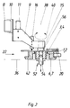
- the device 28 has for clamping and centering a frame 24, in particular a window or door frame or the like, and for moving or pivoting the frame 24 into one or more processing positions on one Processing station 26 on a clamping means 22 movable in the direction of a longitudinal axis 30 or in the conveying direction of the device 28.
- the clamping means 22 has two clamping devices 32, 34, in particular aligned at right angles to one another, for clamping frame parts of the frame 24, in particular, arranged at right angles, such as frame legs 6, 7, fighters 19, frame cross 17 or the like.
- the clamping device 22 is in the direction of one Support 36 of the device 28 can be moved up and down in the vertical axis 38 and pivoted about the pivot axis 38 by an angle 40.
- the clamping devices 32, 34 each have one on the inside of the two profile legs 6, 7 of the Frame corners to lie coming fixed stop 1, 2.
- clamping parts in particular clamping jaws 3 and 4 are arranged on the stop 1, 2 towards and away from the stop 1, 2.
- the clamping means 22 can be pivoted through an angle 40 of approximately 45 ° to 180 °, preferably by angle steps of approximately 45 ° or a multiple thereof, for example approximately 90 °, which can be adjusted by means of a latching device 16.
- a pivoting cylinder 12 is provided on a mounting plate of a support arm 9 for the tensioning means 22 and engages with the associated piston rod 13 on an eye 14 or the like of the tensioning means 22.
- the clamping means 22 is pivoted about a bolt 15 or the pivot axis 38 by the desired angle 40.
- the clamping means 22 is not only 45 °, but rather can also be swiveled by 90 °.
- a latching device 16 according to FIG. 4 is provided, which enables an exact setting of the desired angle 40 for pivoting the clamping means 22.
- clamping devices 32, 34 are actuated by means of clamping cylinders 5 in that the clamping jaws 3, 4 can be moved in the clamping position against the outside of the frame legs 6, 7, whereby the frame 24 is clamped and centered.
- the tensioning means 22 are longitudinally displaceable along a beam 8, for example by means of a toothed belt drive. As a result, the frame 24 to be machined can be moved into the machining position at the machining station 26.
- the tensioning devices 32, 34 are held on a cranked support arm 9, which is connected to the toothed belt drive. To guide the tensioning devices 32, 34 are on the support arm 9 Guide elements 10 are arranged, which are movably mounted on the longitudinal beam 8.
- the tensioning devices 32, 34 In order to bring the tensioning devices 32, 34 into and out of engagement with the frame 24, which is particularly necessary for pivoting or moving the frame 24, the tensioning devices 32, 34 or the tensioning means 22 with respect to the frame 24 or the Longitudinal beam 8 can be moved up and down in the direction of pivot axis 38, which is accomplished by means of a lifting device 11.
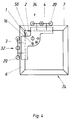
- the support arm 9 has at the free end a holding plate 42 on which the clamping devices 32, 34 and their actuating means, in particular the clamping cylinders 5, are arranged.
- the holding plate 42 is pivotally mounted on the support arm 9 about the pivot axis 38.
- the holding plate 42 is preferably designed as an angle plate or the like and has a recess 50, on the side edges of which the clamping devices 32, 34 are arranged.
- a latching device 52 is provided.
- the latching device 52 preferably has at least two latching bolts 54 which engage in a bore 56 on the holding plate 42, of which only the latching bolt 54 which causes the centering and lies in the pivot axis 38 can be seen.
- the second bolt (not shown) engages in a bore in one leg of the plate 42 and serves to prevent rotation.
- the latching bolts 54 arranged stationary with respect to the processing station 26 can be displaced, for example by means of pneumatic cylinders, in and out of the latched position with the bores 56 of the holding plate 42.
- rollers 20, in particular pressure rollers can also be provided, which on the one hand has the advantage have that optically disturbing impressions on the frame parts due to the clamping are largely avoided. It must be taken into account here that in particular larger frames 24 can reach a weight of up to 150 kg, so that considerable contact forces are required. If conventional clamping jaws are used, optically disruptive impressions on the frame 24 can therefore occur, while this is practically avoided when using rollers 20, in particular pressure rollers.
- the rollers 20 additionally have the advantage that centering is nevertheless possible in the case of a non-simultaneous clamping movement of the clamping devices 32, 34.
- the problem may arise that one clamping device has already clamped a frame part while the other clamping device has not yet come into contact with the corresponding frame part. Then, in particular when using clamping jaws, it can happen that the frame 24 is not in the centering position and cannot be brought into the centering position by the clamping device actuated later, since the clamping device actuated earlier in time has already firmly clamped the frame part or the frame 24 Has.
- the first frame part already clamped by means of the first actuated clamping device can be displaced in the first clamping device due to the effect of the second frame part clamped later and thus the entire frame can be centered even if the two clamping devices are not actuated simultaneously.
- the method for actuating the device 28 according to the invention is shown in individual steps a to g in FIG. 5.
- the frame 24 changes from a position of the device 28 that is dependent on the assembly or manufacturing conditions Move processing station 26.
- the frame 24 can be from a welding machine, in which frame legs or profile pieces are welded together to form the frame, to a processing station 26 for removing welding beads or introducing sealing grooves and the like. the like.
- the frame 24 is received by means of the clamping means 22 by moving the clamping devices 32, 34 along the beam 8 to the frame 24, the clamping devices 32, 34 then being lowered by means of the lifting device 11 and the clamping jaws 3, 4 by means of the Tensioning cylinders 5 are moved against the fixed stops 1, 2 in such a way that the frame section to be machined, in particular a frame corner, comes to lie freely accessible from all sides in the recess 50 of the holding plate 42.
- the frame 24 is not only clamped, but is already centered with respect to the frame part to be machined first, in particular the frame outer or frame inner corner.
- the clamping devices 32, 34 are opened again and raised and moved to the first fighter 19.
- the clamping device 22 has been lowered, the clamping devices 32, 34 are brought back into the bearing position or clamping position, the frame 24 for processing the first fighter connection is moved into the corresponding processing position at the processing station 26 and clamped again against the support 36.
- the first fighter connection is then processed, as shown in FIG. 5c. Unless other fighter connections are present, this operation is repeated, as shown, for example, in Figure 5d.
- the clamping devices 32, 34 are pivoted after opening and lifting by 90 ° according to FIG. 5e and the second frame corner is clamped and processed.
- the frame 24 clamped in the clamping devices 32, 34 is pivoted by 90 ° by pivoting the clamping means 22, as a result of which the position according to FIG. 5f is reached.
- the tensioning devices 32, 34 are opened, raised and lowered analogously to the previous steps, the frame 24 then being pivoted again 90 ° clockwise until the position according to FIG. 5g is reached.
- the third frame leg is then processed in the manner described in FIG. 5b. The processing sequence is repeated until all frame legs or the corner connections located on the frame legs have been processed.
- FIG. 7 it is also possible with the device according to the invention to process so-called frame crosses 17 (FIG. 7d), in which case the clamping means 22 is not to be pivoted by 90 ° but only by 45 °.
- the exemplary embodiments in FIGS. 7a, b and c relate to the previously described processing of the first corner of the frame 24, a fighter connection or the second corner of the frame 24.
- a second clamping means 46 which has a further clamping device 48 and can be moved on the longitudinal beam 8 with a separate toothed belt drive. This ensures that after processing a The first clamping device 22 can be opened and raised while the second clamping device 46 remains in engagement or bearing position with the frame 24 and after opening and lifting the first clamping device 22 moves the frame 24 into the next processing position with respect to the processing station 26.
Landscapes
- Engineering & Computer Science (AREA)
- Mechanical Engineering (AREA)
- Life Sciences & Earth Sciences (AREA)
- Wood Science & Technology (AREA)
- Forests & Forestry (AREA)
- Jigs For Machine Tools (AREA)
Abstract
Description
Die Erfindung betrifft eine Vorrichtung zum Transportieren, Positionieren und/oder Verschwenken eines Rahmens, insbesondere Fenster- oder Türrahmen o. dgl., in wenigstens eine Bearbeitungsposition an einer Bearbeitungsstation.The invention relates to a device for transporting, positioning and / or pivoting a frame, in particular window or door frames or the like, into at least one processing position at a processing station.
Derartige Vorrichtungen werden insbesondere eingesetzt, um einen Fenster- oder Türrahmen an den Rahmenaußen- und -innenschenkeln bzw. -ecken mittels einer Bearbeitungsstation oder -stationen zu bearbeiten, bspw. um Schweißraupen abzutragen oder Dichtungsnuten o. dgl. einzubringen. Bei diesen bekannten Vorrichtungen erfolgt das Transportieren und Einspannen des Rahmens in der Bearbeitungsposition an der Maschine mittels separater Einrichtungen. Zunächst wird der Rahmen zur Bearbeitungsmaschine transportiert und dort mittels einer separaten Einrichtung zentriert, eingespannt und zur Bearbeitung der Rahmenecken bzw. von Kämpferverbindungen oder Rahmenkreuzen o. dgl. entsprechend gewendet.Devices of this type are used in particular to process a window or door frame on the outer and inner legs or corners of the frame by means of a processing station or stations, for example in order to remove weld beads or to introduce sealing grooves or the like. In these known devices, the frame is transported and clamped in the processing position on the machine by means of separate devices. First, the frame is transported to the processing machine, where it is centered, clamped in by means of a separate device, and appropriately turned for processing the frame corners or fighter connections or frame crosses or the like.
Nachteilig hierbei ist der große konstruktive Aufwand sowie das Problem des Positionierens des Rahmens innerhalb der Vorrichtung unter Berücksichtigung der erforderlichen Bewegungsfreiheit der Bearbeitungswerkzeuge der Bearbeitungsstationen.The disadvantage here is the great design effort and the problem of positioning the frame within the device, taking into account the required freedom of movement of the processing tools of the processing stations.
Demgegenüber liegt der Erfindung die Aufgabe zugrunde, eine Vorrichtung der eingangs genannten Art dahingehend weiterzubilden, daß eine konstruktiv einfache Vorrichtung geschaffen wird, bei der darüber hinaus genügend Bewegungsfreiheit für die Bearbeitungswerkzeuge der Bearbeitungsstation vorhanden ist.In contrast, the invention has for its object to develop a device of the type mentioned in such a way that a structurally simple device is created, in addition, enough There is freedom of movement for the processing tools of the processing station.
Diese Aufgabe wird nach der Erfindung bei der Vorrichtung mit den eingangs genannten Merkmalen i. w. dadurch gelöst, daß ein in Richtung einer Längsachse der Vorrichtung verfahrbares Spannmittel vorgesehen ist, das zwei, insbesondere i. w. rechtwinklig zueinander ausgerichtete Spanneinrichtungen zum Einspannen von insbesondere i. w. rechtwinklig angeordneten Rahmenteilen des Rahmens, wie Rahmenschenkel, Kämpfer, Rahmenkreuz o. dgl., aufweist und um eine zur Transportrichtung senkrechte Achse um einen Winkel verschwenkbar ist.This object is achieved according to the invention in the device with the features i. w. solved in that a movable in the direction of a longitudinal axis of the device is provided which two, in particular i. w. clamping devices aligned at right angles to one another for clamping in particular i. w. has frame parts of the frame arranged at right angles, such as frame legs, fighters, frame cross or the like, and can be pivoted through an angle about an axis perpendicular to the transport direction.
Hierdurch wird eine konstruktiv einfache Vorrichtung geschaffen, mit der der Rahmen beim Einspannen selbsttätig positioniert und dann zu der Bearbeitungsstation zur Bearbeitung verfahren wird. Aufgrund der Schwenkbarkeit des Spannmittels besteht zusätzlich die Möglichkeit, den Rahmen zu verschwenken, so daß mittels der Bearbeitungsstation nacheinander sämtliche Rahmenschenkel, insbesondere auf der Rahmeninnenseite wie auch auf der -außenseite abgearbeitet werden können. Die Bearbeitungsstation selbst weist somit keine Spann- oder dgl. Einrichtungen mehr auf, so daß für eine ausreichende Bewegungsfreiheit der Bearbeitungswerkzeuge gesorgt ist.This creates a structurally simple device with which the frame is automatically positioned when it is clamped and then moved to the processing station for processing. Due to the pivotability of the clamping means, there is also the possibility of pivoting the frame, so that all frame legs can be processed one after the other by means of the processing station, in particular on the inside of the frame as well as on the outside. The processing station itself therefore no longer has any clamping or similar devices, so that there is sufficient freedom of movement for the processing tools.
Nach einer ersten besonderen Ausführungsform der Erfindung ist es vorgesehen, daß das Spannmittel bzw. die Spanneinrichtungen in Richtung einer zu einer Auflage der Vorrichtung im wesentlichen senkrechten Achse auf- und abverfahrbar ist bzw. sind. Hierdurch taucht das Spannmittel in das Profil ein, um insbesondere geschlossene Rahmen handhaben zu können. Ein weiterer Vorteil ist, daß durch Anheben des Rahmens eventuell vorstehende Schweißraupen an den zusammengeschweißten Kunststoffprofilstücken keine Behinderung beim Transport des Werkstückes darstellen.According to a first particular embodiment of the invention, it is provided that the tensioning means or the tensioning devices can be moved up and down in the direction of an axis substantially perpendicular to a support of the device. As a result, the clamping device dips into the profile, in order to be able to handle closed frames in particular. Another advantage is that by lifting the frame, any protruding weld beads on the welded together Plastic profile pieces do not represent an obstacle when transporting the workpiece.
Dabei hat es sich gemäß einer vorteilhaften Ausgestaltung der Erfindung als vorteilhaft erwiesen, daß das Spannmittel um Winkel von etwa 45° bis 180°, bevorzugt um, mittels einer Rasteinrichtung einstellbare Winkelschritte von ca. 45° oder ein Vielfaches hiervon verschwenkbar ist. Hierdurch ist die Möglichkeit gegeben, Rahmenaußenecken, Rahmeninnenecken, Rahmenkreuze, Kämpferverbindungen o. dgl. sukzessive nacheinander zu bearbeiten, wobei der Rahmen insbesondere vollautomatisch von der Vorrichtung verfahren bzw. verschwenkt wird. Es versteht sich, daß die angegebenen Winkelschritte auf herkömmliche Rahmen mit rechtwinkliger Rahmenkonstruktion abgestellt sind. Für Sonderausfertigungen, bei denen der Rahmen von der rechtwinkligen Struktur abweicht, sind natürlich entsprechend angepaßte Schwenkwinkel bzw. Winkelschritte einstellbar. Selbstverständlich ist es auch möglich, daß die beiden Spanneinrichtungen gegeneinander verschwenkbar sind, um auch Rahmen mit spitz- oder stumpfwinklig aufeinander zulaufenden Rahmenschenkeln handhaben zu können.It has proven to be advantageous according to an advantageous embodiment of the invention that the clamping means can be pivoted through angles of approximately 45 ° to 180 °, preferably around, by means of a locking device adjustable angle steps of approximately 45 ° or a multiple thereof. This provides the possibility of successively processing frame outer corners, frame inner corners, frame crosses, fighter connections or the like, the frame being moved or pivoted in particular fully automatically by the device. It is understood that the specified angular steps are based on conventional frames with a rectangular frame construction. For special versions in which the frame deviates from the rectangular structure, appropriately adapted swivel angles or angle steps can of course be set. Of course, it is also possible for the two tensioning devices to be pivotable relative to one another in order to be able to handle frames with frame legs tapering at an acute or obtuse angle.
Die Spannvorrichtung ist nach einer anderen vorteilhaften Ausführungsform der Erfindung als Spannzange mit einem vorzugsweise feststehendem Anschlag und einem auf den Anschlag zu und von dem Anschlag weg verfahrbaren Spannteil, insbesondere Spannbacken, ausgebildet. Die feststehenden Anschläge dienen zur Zentrierung des Rahmens sowie als Widerlager für die verfahrbaren Spannteile, so daß die Rahmenteile zwischen den Anschlägen und den Spannteilen sicher zentrierbar und einspannbar sind.According to another advantageous embodiment of the invention, the clamping device is designed as a collet with a preferably fixed stop and a clamping part that can be moved towards and away from the stop, in particular clamping jaws. The fixed stops serve to center the frame and as an abutment for the movable clamping parts, so that the frame parts between the stops and the clamping parts can be centered and clamped securely.
Das Verfahren der Spannteile der Spannzange und/oder der Anschläge in und außer Anlagestellung an das Werkstück bzw. die Rahmenschenkel kann auch durch eine Schwenkbewegung der Spannteile und/oder Anschläge erfolgen. Beispielsweise können die Spannteile bzw. die Anschläge um etwa 90° in und außer Anlagestellung geschwenkt oder weggeklappt werden. Ggf. kann durch diese Maßnahme auf eine Absenkbewegung der Spannmittel verzichtet werden.The movement of the clamping parts of the collet and / or the stops in and out of contact with the workpiece or the frame legs can also by a pivoting movement of the Clamping parts and / or stops are made. For example, the clamping parts or the stops can be pivoted about 90 ° in and out of contact position or folded away. Possibly. can be dispensed with a lowering movement of the clamping means by this measure.
Dabei hat es sich nach einer weiteren, besonders vorteilhaften Ausführungsform der Erfindung als vorteilhaft erwiesen, die ggf. verfahrbaren Spannteile als Rollen, insbesondere Andruckrollen o. dgl. auszubilden. Diese Rollen haben zum einen den Vorteil, daß Impressionen an den Rahmenteilen infolge des Einspannens weitestgehend vermieden werden. Darüber hinaus wird mit dem Einsatz von derartigen Rollen ein im Falle von Spannbacken auftretendes Problem beim Zentrieren des Rahmens vermieden, welches bei nicht simultanen Spannbewegungen der beiden Spannvorrichtungen auftritt. Ist nämlich mittels der einen Spannvorrichtung bereits ein Rahmenteil eingespannt, ohne daß die andere Spannvorrichtung bereits in Anlagestellung an das weitere Rahmenteil getreten ist, kann es vorkommen, daß der Rahmen sich noch nicht in der Zentrierstellung befindet. Bei dem Einsatz herkömmlicher Spannteile kann dann die Situation auftreten, daß das zuletzt in Anlagestellung mit dem Rahmenteil tretende Spannteil nicht mehr in der Lage ist, das entsprechende Rahmenteil gegen den Anschlag in Anlagestellung zu bringen, da der Rahmen bereits durch die erste Spanneinrichtung fest eingespannt ist. Durch den Einsatz von Rollen als Spannteil kann aber der zuerst erfaßte Rahmenteil selbst bei gespannter erster Spanneinrichtung aufgrund der Einwirkung der zweiten Spanneinrichtung dennoch in die zentrierte Stellung verschoben werden.According to a further, particularly advantageous embodiment of the invention, it has proven to be advantageous to design the possibly movable clamping parts as rollers, in particular pressure rollers or the like. On the one hand, these roles have the advantage that impressions on the frame parts as a result of the clamping are largely avoided. In addition, the use of such rollers avoids a problem in the case of clamping jaws when centering the frame, which occurs when the two clamping devices do not simultaneously clamp. If a frame part has already been clamped by means of the one clamping device without the other clamping device already having come into contact with the further frame part, it can happen that the frame is not yet in the centering position. When using conventional clamping parts, the situation may arise that the clamping part that comes last into contact with the frame part is no longer able to bring the corresponding frame part into contact position against the stop, since the frame is already firmly clamped by the first clamping device . However, by using rollers as the tensioning part, the frame part first detected can still be moved into the centered position due to the action of the second tensioning device even when the first tensioning device is tensioned.
Es hat sich nach einer anderen Ausführungsform der Erfindung als vorteilhaft erwiesen, daß das Spannmittel einen Tragarm aufweist, der einends über ein Führungselement an einem in Förderrichtung verlaufenden Balken o. dgl., bspw. mittels eines Zahnriemenantriebs verfahrbar gelagert ist.It has proven to be advantageous according to another embodiment of the invention that the tensioning means has a support arm which at one end via a guide element on a Beam or the like running in the conveying direction, for example, is movably mounted by means of a toothed belt drive.
Von Vorteil ist Tragarm mittels einer Hubvorrichtung bzgl. des Führungselements in Richtung der Schwenkachse auf- und abverfahrbar, so daß ein einfaches Absenken und Anheben des Spannmittels ermöglicht ist.The support arm can advantageously be moved up and down in the direction of the pivot axis by means of a lifting device with respect to the guide element, so that the clamping means can be easily lowered and raised.
Nach einer anderen, konstruktiv besonders vorteilhaften Ausgestaltung der Erfindung weist der Tragarm eine Halteplatte auf, an der die Spannvorrichtungen und deren Betätigungsmittel, wie Spannzylinder o. dgl., angeordnet sind, wobei die Halteplatte verschwenkbar an dem Tragarm gelagert ist.According to another, structurally particularly advantageous embodiment of the invention, the support arm has a holding plate on which the clamping devices and their actuating means, such as clamping cylinders or the like, are arranged, the holding plate being pivotably mounted on the support arm.
Das Verschwenkmittel für die Halteplatte ist als Schwenkzylinder mit zugeordneter Kolbenstange ausgebildet, die einends an der Halteplatte, insbesondere einem Auge der Halteplatte, und anderenends an dem Tragarm angelenkt ist.The pivoting means for the holding plate is designed as a pivot cylinder with an associated piston rod which is articulated on one side on the holding plate, in particular one eye of the holding plate, and on the other end on the support arm.
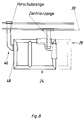
Von Vorteil ist nach einer anderen Ausführungsform der Erfindung entlang der Längsachse bzw. Förderrichtung der Vorrichtung ein zweites Spannmittel verfahrbar angeordnet, welches eine Spanneinrichtung zum Einspannen eines Rahmenteils des Rahmens aufweist. Durch diese Maßnahme kann die Taktzeit zur Bearbeitung des Rahmens reduziert werden, indem nach der Bearbeitung eines Rahmenecks o. dgl. das erste Spannmittel geöffnet und angehoben wird, während das zweite Spannmittel in Eingriff bzw. Anlagestellung mit dem Rahmenteil verbleibt und den Rahmen nach Öffnen unter Anheben des ersten Spannmittels in die nächste Bearbeitungsposition bzgl. der Bearbeitungsstation verfährt.According to another embodiment of the invention, a second clamping means is advantageously arranged to be movable along the longitudinal axis or conveying direction of the device, said clamping means having a clamping device for clamping a frame part of the frame. With this measure, the cycle time for processing the frame can be reduced by opening and lifting the first clamping device after processing a frame corner or the like, while the second clamping device remains in engagement or in the contact position with the frame part and the frame after opening Lifting the first clamping device into the next processing position with respect to the processing station.
Von Vorteil ist das zweite Spannmittel insbesondere mittels eines zweiten Zahnriementriebes o. dgl. unabhängig von dem ersten Spannmittel verfahrbar.The second tensioning means can advantageously be moved independently of the first tensioning means, in particular by means of a second toothed belt drive or the like.
Die Halteplatte ist von Vorteil i. w. als Winkelplatte o. dgl. ausgebildet, die insbesondere im Bereich des Scheitels eine Aussparung aufweist, an deren Seitenrändern die Spannvorrichtungen angeordnet sind. Die Aussparung ist dabei derart positioniert, daß im Bereich der Aussparung das zu bearbeitende Rahmenteil der Innenseite wie auch der Außenseite völlig frei zugänglich ist, so daß die Bearbeitungswerkzeuge der Bearbeitungsstation ohne weiteres allseitig an das zu bearbeitende Rahmenteil heranführbar sind.The holding plate is advantageous i. w. formed as an angle plate or the like, which has a recess, in particular in the region of the apex, on the side edges of which the clamping devices are arranged. The recess is positioned in such a way that the frame part to be machined is completely freely accessible on the inside as well as on the outside in the region of the recess, so that the machining tools of the machining station can be easily approached on all sides to the frame part to be machined.
Nach einer besonderen Ausgestaltung der Erfindung ist es vorgesehen, daß das Spannmittel bzw. deren Halteplatte mittels einer Rasteinrichtung, bspw. wenigstens einem in eine Bohrung an der Halteplatte eingreifenden Rastbolzen, in der Bearbeitungsposition an der Bearbeitungsstation positionierbar ist bzw. sind. Hierdurch werden die Rahmen exakt in die Bearbeitungsposition gebracht und in dieser Position gehalten. Einem Ausschuß infolge von nicht exakter Positionierung der Rahmen in der Bearbeitungsstation ist dadurch vorgebeugt. Bevorzugt sind zwei Rastbolzen vorgesehen, wovon der eine in der Schwenkachse des Spannmittels bzw. der Spannzange liegt und als Zentrierbolzen dient, während der zweite Rastbolzen eine Drehsicherung der Spannzange bewirkt.According to a special embodiment of the invention, it is provided that the clamping means or its holding plate can be positioned in the machining position at the machining station by means of a latching device, for example at least one latching bolt engaging in a hole in the retaining plate. As a result, the frames are brought exactly into the processing position and held in this position. This prevents rejects due to inexact positioning of the frames in the processing station. Two locking bolts are preferably provided, one of which lies in the pivot axis of the clamping means or the collet and serves as a centering bolt, while the second locking bolt ensures that the collet is secured against rotation.
Die Erfindung betrifft auch ein Verfahren für eine erfindungsgemäße Vorrichtung, welches sich dadurch auszeichnet, daß man die Spannmittel hin zum Rahmen verfährt und den Rahmen einspannt, den Rahmen zur Bearbeitungsstation verfährt und bearbeitet, mit den Spannmitteln ggf. den Rahmen erneut einspannt, verfährt und bearbeitet, die Spannmittel um etwa 45° oder ein Vielfaches verschwenkt und den Rahmen einspannt, verfährt und bearbeitet, den eingespannten Rahmen mit dem Spannmittel um etwa 45° oder ein Vielfaches verschwenkt und bearbeitet, ggf. einen oder mehrere der vorhergehenden Schritte wiederholt und den Rahmen weg von der Bearbeitungsstation verfährt und die Spannmittel löst.The invention also relates to a method for a device according to the invention, which is characterized in that the clamping means are moved toward the frame and the frame is clamped, the frame is moved and processed to the processing station, and if necessary the frame is clamped, moved and processed again with the clamping means , the clamping means pivoted by approximately 45 ° or a multiple and clamps the frame, moves and processes, pivots and processes the clamped frame with the clamping means by approximately 45 ° or a multiple, possibly one or more of the preceding steps repeated and moved the frame away from the processing station and loosened the clamping device.
In einer Ausgestaltung des erfindungsgemäßen Verfahrens verfährt man den Rahmen mittels zweiter Spannmittel, sofern die ersten Spannmittel außer Eingriff mit dem Rahmen stehen.In one embodiment of the method according to the invention, the frame is moved by means of second clamping means, provided that the first clamping means are out of engagement with the frame.
Weitere Ziele, Vorteile, Merkmale und Anwendungsmöglichkeiten der vorliegenden Erfindung ergeben sich aus der nachfolgenden Beschreibung der Ausführungsbeispiele anhand der Zeichnungen. Dabei bilden alle beschriebenen und/oder bildlich dargestellten Merkmale für sich oder in beliebiger sinnvoller Kombination den Gegenstand der vorliegenden Erfindung, auch unabhängig von ihrer Zusammenfassung in den Ansprüchen oder deren Rückbeziehung.Further objectives, advantages, features and possible uses of the present invention result from the following description of the exemplary embodiments with reference to the drawings. All of the described and / or illustrated features, alone or in any meaningful combination, form the subject matter of the present invention, regardless of how they are summarized in the claims or their relationship.
Es zeigen:
Figur 1- eine mögliche Ausführungsform eines erfindungsgemäßen Spannmittels in perspektivischer Darstellung,
Figur 2- einen Querschnitt durch das Spannmittel der
Figur 1, Figur 3- in schematischer Darstellung eine Draufsicht auf ein Spannmittel mit eingespanntem Rahmenteil,
Figur 4- in schematischer Darstellung ein Spannmittel mit einer Rasteinrichtung in einer Draufsicht,
- Figur 5a bis g
- in schematischer Darstellung den Funktionsablauf einer erfindungsgemäßen Vorrichtung,
Figur 6- in perspektivischer Darstellung ein mit mehreren Rollen versehenes Spannteil,
- Figur 6a
- eine Seitenansicht der
Figur 6 mit im Querschnitt modifizierten Rahmenteil, - Figur 7a bis d
- verschiedene Positionierungen des Spannmittels für unterschiedliche Rahmenverbindungen, wie eine Eckverbindung, eine Kämpferverbindung, eine zweite Eckverbindung des Rahmens sowie eine Kreuzverbindung und
Figur 8- eine weitere Ausführungsform der erfindungsgemäßen Vorrichtung mit einem zusätzlichen zweiten Spannmittel.
- Figure 1
- a possible embodiment of a clamping device according to the invention in a perspective view,
- Figure 2
- 2 shows a cross section through the clamping device of FIG. 1,
- Figure 3
- a schematic representation of a top view of a clamping device with a clamped frame part,
- Figure 4
- a schematic representation of a clamping device with a locking device in a plan view,
- Figure 5a to g
- a schematic representation of the functional sequence of a device according to the invention,
- Figure 6
- in perspective view a clamping part provided with several rollers,
- Figure 6a
- 6 shows a side view of FIG. 6 with the frame part modified in cross section,
- Figure 7a to d
- different positions of the clamping means for different frame connections, such as a corner connection, a fighter connection, a second corner connection of the frame and a cross connection and
- Figure 8
- a further embodiment of the device according to the invention with an additional second clamping means.
Wie insbesondere aus den Figuren 1 bis 3 ersichtlich ist, weist die Vorrichtung 28 zum Einspannen und Zentrieren eines Rahmens 24, insbesondere eines Fenster- oder Türrahmens o. dgl., und zum Verfahren bzw. Verschwenken des Rahmens 24 in eine oder mehrere Bearbeitungspositionen an einer Bearbeitungsstation 26 ein in Richtung einer Längsachse 30 bzw. in Förderrichtung der Vorrichtung 28 verfahrbares Spannmittel 22 auf. Das Spannmittel 22 besitzt zwei insbesondere i. w. rechtwinklig zueinander ausgerichtete Spanneinrichtungen 32, 34 zum Einspannen von insbesondere i. w. rechtwinklig angeordneten Rahmenteilen des Rahmens 24, wie Rahmenschenkel 6, 7, Kämpfer 19, Rahmenkreuz 17 o. dgl. Das Spannmittel 22 ist in Richtung einer zu einer Auflage 36 der Vorrichtung 28 i. w. senkrechten Achse 38 aufund abverfahrbar sowie um die Schwenkachse 38 um einen Winkel 40 verschwenkter. Die Spanneinrichtungen 32, 34 weisen jeweils ein an der Innenseite der beiden Profilschenkel 6, 7 des Rahmenecks zu liegen kommenden feststehenden Anschlag 1, 2 auf. Auf der gegenüberliegenden Seite, also auf der Rahmenaußenseite sind auf den Anschlag 1, 2 zu und von dem Anschlag 1, 2 weg verfahrbare Spannteile, insbesondere Spannbacken 3 und 4 angeordnet.As can be seen in particular from FIGS. 1 to 3, the
Das Spannmittel 22 ist um Winkel 40 von etwa 45° bis 180°, bevorzugt um mittels einer Rasteinrichtung 16 einstellbare Winkelschritte von ca. 45° oder ein Vielfaches hiervon, bspw. etwa 90°, verschwenkbar. Hierfür ist an einer Montageplatte eines Tragarms 9 für die Spannmittel 22 angelenkter Schwenkzylinder 12 vorgesehen, welcher mit der zugehörigen Kolbenstange 13 an einem Auge 14 o. dgl. des Spannmittels 22 angreift. Durch Ein- und Ausfahren der Kolbenstange 13 erfolgt dann ein Verschwenken des Spannmittels 22 um einen Bolzen 15 bzw. die Schwenkachse 38 um den gewünschten Winkel 40. Das Spannmittel 22 ist je nach spezieller Ausgestaltung des Rahmens 24 nicht nur um bspw. 45°, sondern auch um 90° verschwenkbar. Hierfür ist eine Rasteinrichtung 16 gemäß Figur 4 vorgesehen, welche eine exakte Einstellung des gewünschten Winkels 40 zum Verschwenken des Spannmittels 22 ermöglicht.The clamping means 22 can be pivoted through an
Die Spanneinrichtungen 32, 34 werden mittels Spannzylindern 5 betätigt, indem die Spannbacken 3, 4 in Spannstellung gegen die Außenseite der Rahmenschenkel 6, 7 gefahren werden können, wodurch der Rahmen 24 eingespannt und zentriert wird.The
Die Spannmittel 22 sind längs eines Balkens 8 längsverschieblich, bspw. mittels eines Zahnriemenantriebes angeordnet. Hierdurch kann der zu bearbeitende Rahmen 24 in die Bearbeitungsposition an der Bearbeitungsstation 26 gefahren werden. Die Spanneinrichtungen 32, 34 sind an einem abgekröpften Tragarm 9 gehalten, welcher mit dem Zahnriemenantrieb verbunden ist. Zur Führung der Spanneinrichtungen 32, 34 sind an dem Tragarm 9 Führungselemente 10 angeordnet, welche an dem Längsbalken 8 verfahrbar gelagert sind. Um die Spanneinrichtungen 32, 34 in und außer Eingriff mit dem Rahmen 24 zu bringen, was insbesondere für das Verschwenken bzw. Verfahren des Rahmens 24 erforderlich ist, sind die Spanneinrichtungen 32, 34 bzw. die Spannmittel 22 bzgl. des Rahmens 24 bzw. des Längsbalkens 8 in Richtung der Schwenkachse 38 auf- und abverfahrbar, was mittels einer Hubvorrichtung 11 bewerkstelligt wird.The tensioning means 22 are longitudinally displaceable along a
Der Tragarm 9 weist an dem freien Ende eine Halteplatte 42 auf, an der die Spanneinrichtungen 32, 34 und deren Betätigungsmittel, insbesondere die Spannzylinder 5, angeordnet sind. Die Halteplatte 42 ist dabei um die Schwenkachse 38 verschwenkbar an dem Tragarm 9 gelagert. Die Halteplatte 42 ist bevorzugt als Winkelplatte o. dgl. ausgebildet und weist eine Aussparung 50 auf, an deren Seitenrändern die Spanneinrichtungen 32, 34 angeordnet sind.The
Um ein exaktes Positionierung der Halteplatte 42 in der jeweiligen Bearbeitungsposition an der Bearbeitungsstation 26 zu ermöglichen, ist eine Rasteinrichtung 52 vorgesehen. Die Rasteinrichtung 52 weist vorzugsweise wenigstens zwei in eine Bohrung 56 an der Halteplatte 42 eingreifende Rastbolzen 54 auf, wovon in Figur 2 nur der die Zentrierung bewirkende, in der Schwenkachse 38 liegende Rastbolzen 54 zu erkennen ist. Der zweite (nicht dargestellte) Bolzen greift in eine Bohrung an einem Schenkel der Platte 42 ein und dient zur Drehsicherung. Die ortsfest bzgl. der Bearbeitungsstation 26 angeordneten Rastbolzen 54 sind bspw. mittels Pneumatikzylinder in und außer Raststellung mit den Bohrungen 56 der Halteplatte 42 verschiebbar.In order to enable exact positioning of the holding
Wie insbesondere aus den Figuren 6, 6a ersichtlich ist, können anstelle der Spannbacken 3, 4 auch Rollen 20, insbesondere Andruckrollen vorgesehen sein, die zum einen den Vorteil aufweisen, daß optisch störende Impressionen an den Rahmenteilen aufgrund des Einspannens weitestgehend vermieden werden. Hierbei ist zu berücksichtigen, daß insbesondere größere Rahmen 24 ein Gewicht von bis zu 150 kg erreichen können, so daß erhebliche Anpreßkräfte erforderlich sind. Im Falle des Einsatzes von herkömmlichen Spannbacken kann es deshalb zu optisch störenden Impressionen an dem Rahmen 24 kommen, während dies bei dem Einsatz von Rollen 20, insbesondere Andruckrollen, praktisch vermieden wird.As can be seen in particular from FIGS. 6, 6a, instead of the clamping
Die Rollen 20 haben zusätzlich den Vorteil, daß bei einer nicht simultanen Spannbewegung der Spanneinrichtungen 32, 34 dennoch eine Zentrierung möglich ist. Bei einer nicht simultanen Spannbewegung tritt nämlich unter Umständen das Problem auf, daß eine Spannvorrichtung bereits ein Rahmenteil eingespannt hat, während die andere Spannvorrichtung noch nicht in Anlagestellung an das entsprechende Rahmenteil getreten ist. Dann kann es insbesondere bei Einsatz von Spannbacken vorkommen, daß sich der Rahmen 24 nicht in Zentrierstellung befindet und auch durch die zeitlich spätere betätigte Spanneinrichtung nicht in Zentrierstellung gebracht werden kann, da die zeitlich früher betätigte Spannvorrichtung bereits das Rahmenteil bzw. den Rahmen 24 fest eingespannt hat. Im Falle des Einsatzes von Rollen kann jedoch das erste, bereits mittels der zuerst betätigten Spanneinrichtung eingespannte Rahmenteil aufgrund der Wirkung des zeitlich später gespannten zweiten Rahmenteils in der ersten Spanneinrichtung verschoben und somit der gesamte Rahmen auch bei nicht simultaner Betätigung der beiden Spanneinrichtungen zentriert werden.The
Das Verfahren zur Betätigung der erfindungsgemäßen Vorrichtung 28 ist in einzelnen Schritten a bis g in der Figur 5 dargestellt. In der Ausgangsstellung wird der Rahmen 24 von einer von den Montageverhältnissen bzw. Fertigungsverhältnissen abhängigen Position von der Vorrichtung 28 zu der Bearbeitungsstation 26 verfahren. Bspw. kann der Rahmen 24 von einer Schweißmaschine, in welcher Rahmenschenkel bzw. Profilstücke zu dem Rahmen zusammengeschweißt werden, zu einer Bearbeitungsstation 26 zum Abtragen von Schweißraupen bzw. Einbringen von Dichtungsnuten u. dgl. verfahren werden. Von dieser Ausgangsposition wird der Rahmen 24 mittels des Spannmittels 22 aufgenommen, indem die Spanneinrichtungen 32, 34 längs des Balkens 8 zu dem Rahmen 24 verfahren werden, wobei die Spanneinrichtungen 32, 34 anschließend mittels der Hubvorrichtung 11 abgesenkt und die Spannbacken 3, 4 mittels der Spannzylinder 5 gegen die feststehenden Anschläge 1, 2 verfahren werden, derart, daß der zu bearbeitende Rahmenabschnitt, insbesondere eine Rahmenecke, in der Aussparung 50 der Halteplatte 42 von allen Seiten frei zugänglich zu liegen kommt. Nach Betätigung der Spanneinrichtungen 32, 34 ist der Rahmen 24 nicht nur eingespannt, sondern bereits bzgl. des als erstes, zu bearbeitenden Rahmenteils, insbesondere der Rahmenaußen- bzw. Rahmeninnenecke zentriert.The method for actuating the
Anschließend wird der Rahmen 24 an die Bearbeitungsstation 26 verfahren und das Spannmittel 22 mittels der Hubvorrichtung 11 auf eine Auflage 36 der Vorrichtung 28 gespannt. Dieser Verfahrensschritt ist in Figur 5b dargestellt.The
Nach Bearbeitung der ersten Ecke des Rahmens 24 werden die Spanneinrichtungen 32, 34 wieder geöffnet und angehoben und bis zu dem ersten Kämpfer 19 verfahren. Nach Absenkung des Spannmittels 22 werden die Spanneinrichtungen 32, 34 wieder in Anlagestellung bzw. Spannstellung gebracht, der Rahmen 24 zur Bearbeitung der ersten Kämpferverbindung in die entsprechende Bearbeitungsposition an der Bearbeitungsstation 26 verfahren und wieder gegen die Auflage 36 gespannt. Sodann erfolgt die Bearbeitung der ersten Kämpferverbindung, wie dies in der Figur 5c dargestellt ist. Sofern weitere Kämpferverbindungen vorhanden sind, wiederholt sich dieser Arbeitsvorgang, wie dies bspw. in Figur 5d dargestellt ist. Zum Bearbeiten des in Transportrichtung letzten Rahmenecks werden die Spanneinrichtungen 32, 34 nach Öffnen und Anheben um 90° gemäß Figur 5e geschwenkt und das zweite Rahmeneck eingespannt und bearbeitet. Nach Bearbeitung aller Eckverbindungen an einem Rahmenschenkel wird der in den Spanneinrichtungen 32, 34 eingespannte Rahmen 24 durch eine Schwenkung des Spannmittels 22 um 90° verschwenkt, wodurch die Position gemäß Figur 5f erreicht wird. Nach einer entsprechenden Bearbeitung aller Eckverbindungen des zweiten Rahmenschenkels werden die Spanneinrichtungen 32, 34 analog den vorhergehenden Schritten geöffnet, angehoben und abgesenkt, wobei anschließend der Rahmen 24 erneut um 90° im Uhrzeigersinn verschwenkt wird, bis die Stellung gemäß Figur 5g erreicht ist. Anschließend findet eine Bearbeitung des dritten Rahmenschenkels in der Weise, wie ausgehend von Figur 5b beschrieben, statt. Der Bearbeitungsablauf wiederholt sich, bis alle Rahmenschenkel bzw. die an den Rahmenschenkeln befindlichen Eckverbindungen abgearbeitet sind.After processing the first corner of the
Wie aus Figur 7 ersichtlich, ist es mit der erfindungsgemäßen Vorrichtung ebenfalls möglich, sogenannte Rahmenkreuze 17 (Figur 7d) zu bearbeiten, wobei in diesem Fall das Spannmittel 22 nicht um 90°, sondern nur um 45° zu schwenken ist. Die Ausführungsbeispiele der Figur 7a, b und c beziehen sich auf die vorher bereits beschriebene Bearbeitung der ersten Ecke des Rahmens 24, einer Kämpferverbindung bzw. der zweiten Ecke des Rahmens 24.As can be seen from FIG. 7, it is also possible with the device according to the invention to process so-called frame crosses 17 (FIG. 7d), in which case the clamping means 22 is not to be pivoted by 90 ° but only by 45 °. The exemplary embodiments in FIGS. 7a, b and c relate to the previously described processing of the first corner of the
Um die Taktzeit zur Bearbeitung des Rahmens zu reduzieren, ist es nach einer weiteren Ausführungsform der Erfindung auch möglich, ein zweites Spannmittel 46 gemäß Figur 8 einzusetzen, welches eine weitere Spannvorrichtung 48 aufweist und mit einem separaten Zahnriementrieb an dem Längsbalken 8 verfahrbar ist. Hierdurch wird erreicht, daß nach der Bearbeitung eines Rahmenecks das erste Spannmittel 22 geöffnet und angehoben werden kann, während das zweite Spannmittel 46 in Eingriff bzw. Anlagestellung mit dem Rahmen 24 verbleibt und nach dem Öffnen und Anheben des ersten Spannmittels 22 den Rahmen 24 in die nächste Bearbeitungsposition bzgl. der Bearbeitungsstation 26 verschiebt.In order to reduce the cycle time for processing the frame, it is also possible, according to a further embodiment of the invention, to use a second clamping means 46 according to FIG. 8, which has a
- 11
- - Anschlag- Attack
- 22nd
- - Anschlag- Attack
- 33rd
- - Spannbacke- jaw
- 44th
- - Spannbacke- jaw
- 55
- - Spannzylinder- clamping cylinder
- 66
- - Rahmenschenkel- frame leg
- 77
- - Rahmenschenkel- frame leg
- 88th
- - Balken- Bar
- 99
- - Tragarm- Beam
- 1010th
- - Führungselement- guide element
- 1111
- - Hubvorrichtung- lifting device
- 1212th
- - Schwenkzylinder- swivel cylinder
- 1313
- - Kolbenstange- piston rod
- 1414
- - Auge- eye
- 1515
- - Bolzen- Bolt
- 1616
- - Rasteinrichtung- locking device
- 1717th
- - Rahmenkreuz- frame cross
- 1919th
- - Kämpfer- fighter
- 2020th
- - Rolle- role
- 2222
- - Spannmittel- clamping devices
- 2424th
- - Rahmen- Frame
- 2626
- - Bearbeitungsstation- processing station
- 2828
- - Vorrichtung- Contraption
- 3030th
- - Längsachse- longitudinal axis
- 3232
- - Spanneinrichtung- tensioning device
- 3434
- - Spanneinrichtung- tensioning device
- 3636
- - Auflage- edition
- 3838
- - Schwenkachse- swivel axis
- 4040
- - Winkel- Angle
- 4242
- - Halteplatte- Retaining plate
- 4444
- - Verschwenkmittel- pivoting means
- 4646
- - Spannmittel- clamping devices
- 4848
- - Spannvorrichtung- tensioning device
- 5050
- - Aussparung- recess
- 5252
- - Rasteinrichtung- locking device
- 5454
- - Rastbolzen- locking bolts
- 5656
- - Bohrung- Drilling
Claims (16)
Applications Claiming Priority (2)
| Application Number | Priority Date | Filing Date | Title |
|---|---|---|---|
| DE19525279 | 1995-07-13 | ||
| DE19525279 | 1995-07-13 |
Publications (1)
| Publication Number | Publication Date |
|---|---|
| EP0753378A1 true EP0753378A1 (en) | 1997-01-15 |
Family
ID=7766567
Family Applications (1)
| Application Number | Title | Priority Date | Filing Date |
|---|---|---|---|
| EP96111377A Withdrawn EP0753378A1 (en) | 1995-07-13 | 1996-07-15 | Device and method for transporting, positioning and/or turning of a frame |
Country Status (1)
| Country | Link |
|---|---|
| EP (1) | EP0753378A1 (en) |
Cited By (4)
| Publication number | Priority date | Publication date | Assignee | Title |
|---|---|---|---|---|
| DE20101639U1 (en) * | 2001-01-29 | 2002-06-06 | Urban Gmbh & Co Maschinenbau Kg, 87700 Memmingen | Device for removing a frame from a frame processing or frame manufacturing machine |
| EP1882568A1 (en) | 2006-07-26 | 2008-01-30 | KMW-Engineering GmbH | Device and method for moving window frames |
| ITMI20082334A1 (en) * | 2008-12-29 | 2010-06-30 | Me C Al S P A | APPARATUS FOR THE CONTEMPORARY DRILLING AND HANDLING BETWEEN WORK STATIONS OF A WORKING PIECE. |
| US20160039063A1 (en) * | 2014-08-08 | 2016-02-11 | Murata Machinery, Ltd. | Workpiece conveying device and machine tool |
Citations (3)
| Publication number | Priority date | Publication date | Assignee | Title |
|---|---|---|---|---|
| US3927819A (en) * | 1973-10-01 | 1975-12-23 | Delog Detag Flachglas Ag | Method of treating the corners of planar polygonal workpieces |
| EP0283403A1 (en) * | 1987-03-20 | 1988-09-21 | R.G.D. S.A. | Programmable manipulator for feeding a machine tool |
| EP0410173A2 (en) * | 1989-07-22 | 1991-01-30 | Maschinenfabrik Gubisch GmbH | Grooving machine |
-
1996
- 1996-07-15 EP EP96111377A patent/EP0753378A1/en not_active Withdrawn
Patent Citations (3)
| Publication number | Priority date | Publication date | Assignee | Title |
|---|---|---|---|---|
| US3927819A (en) * | 1973-10-01 | 1975-12-23 | Delog Detag Flachglas Ag | Method of treating the corners of planar polygonal workpieces |
| EP0283403A1 (en) * | 1987-03-20 | 1988-09-21 | R.G.D. S.A. | Programmable manipulator for feeding a machine tool |
| EP0410173A2 (en) * | 1989-07-22 | 1991-01-30 | Maschinenfabrik Gubisch GmbH | Grooving machine |
Cited By (4)
| Publication number | Priority date | Publication date | Assignee | Title |
|---|---|---|---|---|
| DE20101639U1 (en) * | 2001-01-29 | 2002-06-06 | Urban Gmbh & Co Maschinenbau Kg, 87700 Memmingen | Device for removing a frame from a frame processing or frame manufacturing machine |
| EP1882568A1 (en) | 2006-07-26 | 2008-01-30 | KMW-Engineering GmbH | Device and method for moving window frames |
| ITMI20082334A1 (en) * | 2008-12-29 | 2010-06-30 | Me C Al S P A | APPARATUS FOR THE CONTEMPORARY DRILLING AND HANDLING BETWEEN WORK STATIONS OF A WORKING PIECE. |
| US20160039063A1 (en) * | 2014-08-08 | 2016-02-11 | Murata Machinery, Ltd. | Workpiece conveying device and machine tool |
Similar Documents
| Publication | Publication Date | Title |
|---|---|---|
| DE1910977C3 (en) | Clamping device on a workbench | |
| DE3823635C2 (en) | ||
| DE4431384A1 (en) | Device for framing vehicle bodies | |
| AT514821B1 (en) | Bending press and bending process | |
| DE3607020A1 (en) | MOUNTING DEVICE FOR BODY PARTS OF MOTOR VEHICLES | |
| EP2070686B1 (en) | Device and method for welding plastic section pieces | |
| DE10031216A1 (en) | Cutting device has main stock vice mechanism, feed mechanism and workpiece draw mechanism which holds end point of residual length at predetermined position when this is shorter than predetermined cutting length | |
| DE69607159T2 (en) | MULTIPURPOSE HEAD SHAPE AND FINISHING DEVICE | |
| DE4232289C2 (en) | Method and device for pivoting a window frame in the area of a corner cleaning machine | |
| DE2734848A1 (en) | WORK TABLE OF A MACHINE TOOL | |
| EP0460654A1 (en) | Apparatus for the finishing on window frames or the like | |
| DE3312331A1 (en) | DEVICE FOR AUTOMATIC CLAMPING AND RELAXING OF WORKPIECE CARRIERS | |
| DE69008120T2 (en) | Device for the gradual positioning, processing and post-treatment of corners of window or door frames made of plastic in a laterally arranged work station. | |
| EP0753378A1 (en) | Device and method for transporting, positioning and/or turning of a frame | |
| DE7416105U (en) | Device for joining two lengths of strip or sheet metal at the end by flash welding | |
| DE10017315C2 (en) | Device for the movable mounting of an upper mold | |
| EP0618032B1 (en) | Device for the treatment of cornerjoints of window or door frames made of welded plastic profiles | |
| EP0623420A1 (en) | Transporting and locating device | |
| EP4100207A1 (en) | Screw clamp | |
| DE10115653B4 (en) | Clamping system for clamping and possibly centering of profile frames in combination with a cleaning device with at least two processing units and associated method | |
| DE4122567A1 (en) | MOLDING PIECE CLAMPING DEVICE WITH CLAMPING MECHANISM AND CONFIRMATION MECHANISM | |
| EP1800780A2 (en) | Machining device for the machining of corner joints of window frames or door frames | |
| DE9103838U1 (en) | Welding device for rectangular frames, especially window frames | |
| DE4111596C2 (en) | Method and device for machining the corner connections of welded frames | |
| DE10024926C2 (en) | Sheathing machine with detachable retaining rings on the machine frame |
Legal Events
| Date | Code | Title | Description |
|---|---|---|---|
| PUAI | Public reference made under article 153(3) epc to a published international application that has entered the european phase |
Free format text: ORIGINAL CODE: 0009012 |
|
| AK | Designated contracting states |
Kind code of ref document: A1 Designated state(s): AT BE DE FR GB |
|
| 17P | Request for examination filed |
Effective date: 19961207 |
|
| 17Q | First examination report despatched |
Effective date: 19980821 |
|
| STAA | Information on the status of an ep patent application or granted ep patent |
Free format text: STATUS: THE APPLICATION IS DEEMED TO BE WITHDRAWN |
|
| 18D | Application deemed to be withdrawn |
Effective date: 19990422 |