EP0752272A1 - Flour milling machine - Google Patents
Flour milling machine Download PDFInfo
- Publication number
- EP0752272A1 EP0752272A1 EP96304883A EP96304883A EP0752272A1 EP 0752272 A1 EP0752272 A1 EP 0752272A1 EP 96304883 A EP96304883 A EP 96304883A EP 96304883 A EP96304883 A EP 96304883A EP 0752272 A1 EP0752272 A1 EP 0752272A1
- Authority
- EP
- European Patent Office
- Prior art keywords
- rolls
- roll
- metal rolls
- flour mill
- metal
- Prior art date
- Legal status (The legal status is an assumption and is not a legal conclusion. Google has not performed a legal analysis and makes no representation as to the accuracy of the status listed.)
- Granted
Links
Images


Classifications
-
- B—PERFORMING OPERATIONS; TRANSPORTING
- B02—CRUSHING, PULVERISING, OR DISINTEGRATING; PREPARATORY TREATMENT OF GRAIN FOR MILLING
- B02C—CRUSHING, PULVERISING, OR DISINTEGRATING IN GENERAL; MILLING GRAIN
- B02C4/00—Crushing or disintegrating by roller mills
- B02C4/02—Crushing or disintegrating by roller mills with two or more rollers
- B02C4/06—Crushing or disintegrating by roller mills with two or more rollers specially adapted for milling grain
-
- B—PERFORMING OPERATIONS; TRANSPORTING
- B02—CRUSHING, PULVERISING, OR DISINTEGRATING; PREPARATORY TREATMENT OF GRAIN FOR MILLING
- B02C—CRUSHING, PULVERISING, OR DISINTEGRATING IN GENERAL; MILLING GRAIN
- B02C4/00—Crushing or disintegrating by roller mills
- B02C4/28—Details
-
- B—PERFORMING OPERATIONS; TRANSPORTING
- B02—CRUSHING, PULVERISING, OR DISINTEGRATING; PREPARATORY TREATMENT OF GRAIN FOR MILLING
- B02C—CRUSHING, PULVERISING, OR DISINTEGRATING IN GENERAL; MILLING GRAIN
- B02C4/00—Crushing or disintegrating by roller mills
- B02C4/28—Details
- B02C4/30—Shape or construction of rollers
Definitions
- the present invention relates to a flour mill for pulverizing grains and, more particularly, it relates to a flour mill in which each of metal rolls is removably mounted to a shaft in a cantilever form.
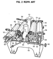
- Figs. 1 and 2 illustrate the so-called duplex type flour mill 57, Fig. 1 schematically showing an external view of the mill and Fig. 2 schematically showing a detailed internal structure thereof.
- Fig. 2 illustrates the so-called duplex type flour mill 57, Fig. 1 schematically showing an external view of the mill and Fig. 2 schematically showing a detailed internal structure thereof.
- two pairs of rolls 51, 52 are arranged symmetrically on both the sides of the machine frame 53. Each of the rolls has an axial length of about 1,000 mm.
- the inner rolls 51, 51 are high speed rolls that are driven at an enhanced rate of revolution and each of which is rotatably carried at the opposite ends by a pair of fixed bearings 54, 54 that are rigidly secured to the frame 53, whereas the outer rolls 52, 52 are low speed rolls that are driven at a reduced rate of revolution and each of which is also carried at the opposite ends by a pair of movable bearings 55, 55.
- Each of the movable bearings 55, 55 is swingable around a pivot pin 56 and controlled by a roll gap adjusting means.
- Each of the rolls 51 is linked to the corresponding roll 52 by engaging a control rod 58 to the corresponding movable bearing 55, the control rod 58 being connected to the corresponding fixed bearing 54 by way of an eccentrically located wheel 61.
- Fig. 2 shows the state in which the control rod 58 is not engaged with the corresponding movable bearing 55
- the right half portion shows the state in which the control rod 58 is engaged with the corresponding movable bearing 55.
- the flour mill 57 operates optimally for producing good flour when the roll diameter is 250 mm, the peripheral speed ratio is 2.5:1, the peripheral running speed of the high speed roll is about 8 m/sec and the rate of feeding grain to the rolls is about 5 t/h per 1 meter of the length of the rolls.
- the rolls 51 and 52 of the conventional flour mill are axially as long as 1,000 mm, each of them has to be carried by the bearings 54 and 55 at both the end portions. This forces the milling chamber of the flour mill 57 to be located in the internal space defined by the bearings 54 and 55 arranged on the frame 53, so that the operator of the mill is prevented from directly viewing the inside of the milling chamber to monitor the on-going milling operation.
- a flour mill having at least a pair of metal rolls having peripheral speeds different from each other for pulverizing grains therebetween, the flour mill comprising:
- a part of the cover surrounding the milling chamber defined by the paired rolls may preferably be constituted by a transparent member.
- each of the rolls can be safely held in position by mounting it only at an end of the rotary shaft that is rotatably carried by the frame of the mill.
- the roll can be replaced simply by pulling it out from the rotary shaft and fitting and securing a new one to the rotary shaft, so that the cumbersome operation of disassembling the bearings required for known flour mills is completely eliminated and the entire replacing operation can be carried out easily in a short period of time.
- each of the rolls is mounted in a cantilever form with respect to an end of the rotary shaft carried by the frame of the flour mill and the cover of the milling chamber defined by the paired rolls comprises a transparent member as a part thereof, the on-going milling operation carried out within the milling chamber is clearly visible to and can be monitored by the operator.
- a flour mill of this embodiment is generally denoted by reference numeral 1 and comprises a grain storing section 2 for storing the grains to be milled; a grain feeding section 5 including a pair of feed rolls 3 and 4 that are driven by a motor; and a milling section 8 including a pair of metal rolls 6 and 7 for pulverizing the grains fed from the grain feeding section 5.
- a plurality of grain sensors 10 are arranged longitudinally in a hopper 9 of the grain storing section 2. Each of the sensors 10 outputs an electric signal representing the presence or absence of the grain at the position where the sensor is located.
- the feed rolls 3 and 4 in the grain feeding section 5 are controlled for their acceleration or deceleration according to the signals outputted from the sensors 10.
- a gate plate 11 is arranged on either one of the feed rolls 3 and 4 in the grain feeding section 5 and provided with a gate control cylinder (not shown) so that the gate plate 11 may be positioned between a fully open position and a fully closed position by the operation of the gate control cylinder according to the electric signals from the sensors 10 or the rate of revolution of the feed rolls 3 and 4.
- a guide chute 12 is vertically arranged next to the feed rolls 3 and 4. The lower end of the guide chute 12 is located above the space between the roll 6 and the roll 7 of the milling section 8.
- the grain feeding section 5 has a feed chamber 14 that contains the feed rolls 3 and 4 therein and is provided with a transparent cover 13, so that the operator can directly view and monitor the grain feeding operation performed by the feed rolls 3 and 4.
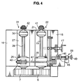
- a table 16 is rigidly secured on a frame 15 and slidably carries thereon a sliding table 18 that is operated to slide by means of a control handle 17.
- a fixed bearing section 22 is arranged on the sliding table 18 and comprises front and rear bearings 20 and 21 for carrying the front and rear portions of a rotary shaft 19. As shown in Fig.
- a movable bearing section 31 is arranged at a lateral side of the fixed bearing section 22 and comprises beds 23 and 24 rigidly secured to the table 16, fixed shafts 25 and 26 carried respectively by the cradles 23 and 24, a rotatable table 27 rotatably supported on the fixed shafts 25 and 26 and bearings 29 and 30 rigidly secured onto the rotatable table 27 to carry front and rear portions of a rotary shaft 28.
- the grain milling rolls 6 and 7 each having a diameter of 250 mm and a length between 100 and 500 mm, more specifically 150 mm in this embodiment, are respectively fitted, in the cantilever form, to the front ends of the rotary shafts 19 and 28 and arranged outside the frame 15.
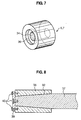
- Each of the grain milling rolls 6 and 7 is provided along its central axis with a shaft receiving hole 34 for receiving the corresponding rotary shaft 19 or 28. Additionally, each of the grain milling rolls 6 and 7 is provided at an end thereof with a recess 36 for receiving an annular locking member 35 (see Fig. 6) for locking the rotary shaft 19 or 28 in position.
- the locking member 35 is so configured that it is stressed to expand at the outer periphery and contract at the inner periphery when bolts provided on it are driven for being tightened.
- the rolls 6 and 7 are secured to the respective rotary shafts 19 and 29 as the former are slidably mounted onto the latter with the shaft receiving holes 34, 34 receiving the respective shafts and the locking members 35, 35 are fitted to the respective recesses 36, 36 of the rolls 6 and 7 and driven for tightening. If the rolls are brake rolls that are threaded over the entire peripheral surface, recesses 36, 36 may be formed on the opposite ends of each of the rolls so that the rolls may be selectively fitted reversely to the respective shafts to realize different combinations of thread pitches (e.g., dull and dull, dull and sharp, sharp and sharp, and sharp and dull).
- thread pitches e.g., dull and dull, dull and sharp, sharp and sharp, and sharp and dull.
- the shaft receiving hole 32 and the corresponding end portion of the shaft 37 may be tapered as shown in Fig. 8 so that the shaft 37 and the roll 38 can be secured to each other by means of bolts 40 with a locking member 39 disposed therebetween. In this way, the roll may revolve without any swinging motion.
- the rear ends of the rotary shafts 19 and 28 are linked respectively to motors 43 and 44 by way of pulleys 41, 42 and belts.
- the motor 43 drives the roll 6 on the fixed bearing section 22 to rotate at a peripheral speed of 12 to 30 m/sec
- the motor 44 drives the roll 7 on the movable bearing section 31 to rotate at a peripheral speed greater than that of the roll 6 on the fixed bearing section 22.
- the ratio of the peripheral speed of the high speed roll 6 to that of the low speed roll 7 is typically 1.1 through 3.0 to 1.
- the ratio is 1.5 through 3.0 to 1 in the case of so-called brake rolls, whereas it is 1.1 through 1.5 to 1 in the case of smooth rolls.
- a link rod 47 is arranged above the bearing 29 of the movable bearing section 31 through a spring 48, to drive the rotatable table 27 to rotate around the fixed shafts 25 and 26 in response to upward or downward movement of a rod 46 of a roll holding/releasing air cylinder 45 so that the roll 7 may be moved to and from the roll 6.
- a crank 65 is pivotably fitted to the lower end of the air cylinder 45 (see Fig. 5) so that the air cylinder 45 may be moved up and down by means of a roll gap adjusting handle 49 in order to finely control the gap between the roll 6 and roll 7 by way of the link rod 47 (see Fig. 4).
- the rolls 6 and 7 are housed in a milling chamber 67, which is provided with a transparent cover 66 removably fitted to the frame 15.
- Reference numeral 68 denotes a collecting hopper for receiving the milled flour in the milling chamber 67 and transferring it to the next station by a conveyor means.
- Reference numeral 33 denotes a flap door for monitoring the milled flour in the collecting hopper.
- the cover 66 When replacing the rolls 6 and 7 of the flour mill 1, the cover 66 is removed from the frame 15 to expose the rolls 6 and 7. Then, the bolts of the locking members 35, 35 disposed in the respective recesses 36, 36 for securing the rolls 6 and 7 respectively to the rotary shafts 19 and 28 are loosened to release and take out the locking members from the recesses 36, 36 and, subsequently, the rolls 6 and 7 are removed from the respective rotary shafts 19 and 28.
- the rolls 6 and 7 can be fitted to the respective rotary shafts 19 and 28 by reversely following the above steps.
- wheat grains are fed for pulverizing to a flour mill according to the invention comprising rolls with a diameter of 250 mm, a peripheral speed ratio of the high speed roll to the low speed roll of 2.5:1 and the peripheral speed of the high speed roll of 20 m/sec at a rate of 10 t/h per 1 meter of the roll and the obtained flour was sifted through a sieve.
- the ash contents of the coarse particles retained by the sieve were calculated for different particle sizes and compared with the corresponding values obtained by a known flour mill comprising rolls with a diameter of 250 mm, a peripheral speed ratio of the high speed roll to the low speed roll of 2.5:1 and the peripheral speed of the high speed roll of 8 m/sec, to which wheat grains are fed at a rate of 5 t/h per 1 meter of the high speed roll.
- a known flour mill comprising rolls with a diameter of 250 mm, a peripheral speed ratio of the high speed roll to the low speed roll of 2.5:1 and the peripheral speed of the high speed roll of 8 m/sec, to which wheat grains are fed at a rate of 5 t/h per 1 meter of the high speed roll.
- the particle size distributions of the milled flour of the two mills were compared (Figs. 9 and 10).
- the ash contents and the particle size distributions of the two mills did not show any significant difference, so that a flour mill according to the invention can be made comparable
Landscapes
- Engineering & Computer Science (AREA)
- Food Science & Technology (AREA)
- Crushing And Grinding (AREA)
Abstract
Description
- The present invention relates to a flour mill for pulverizing grains and, more particularly, it relates to a flour mill in which each of metal rolls is removably mounted to a shaft in a cantilever form.
- A known flour mill will be first described by referring to Figs. 1 and 2 of the accompanying drawings. Figs. 1 and 2 illustrate the so-called duplex
type flour mill 57, Fig. 1 schematically showing an external view of the mill and Fig. 2 schematically showing a detailed internal structure thereof. As shown in Fig. 2, two pairs ofrolls machine frame 53. Each of the rolls has an axial length of about 1,000 mm. Theinner rolls bearings frame 53, whereas theouter rolls movable bearings movable bearings pivot pin 56 and controlled by a roll gap adjusting means. Each of therolls 51 is linked to thecorresponding roll 52 by engaging acontrol rod 58 to the correspondingmovable bearing 55, thecontrol rod 58 being connected to the corresponding fixed bearing 54 by way of an eccentrically locatedwheel 61. The left half portion of Fig. 2 shows the state in which thecontrol rod 58 is not engaged with the correspondingmovable bearing 55, whereas the right half portion shows the state in which thecontrol rod 58 is engaged with the correspondingmovable bearing 55. By the operation of anair cylinder 59 connected to the eccentrically locatedwheel 61 or agap adjusting handle 60 connected to theair cylinder 59, themovable bearing 55 is moved toward or away from the fixed bearing 54 so that the gap between theroll 52 and theroll 51 is adjusted. - Since the
rolls - If the rolls are brake rolls, the
flour mill 57 operates optimally for producing good flour when the roll diameter is 250 mm, the peripheral speed ratio is 2.5:1, the peripheral running speed of the high speed roll is about 8 m/sec and the rate of feeding grain to the rolls is about 5 t/h per 1 meter of the length of the rolls. - In the case where the
rolls conventional flour mill 57 are to be replaced by new ones, thecontrol rods 58 are first disengaged from themovable bearings 55 to separate therolls 51 from therespective rolls 52, which are then released from the fixed andmovable bearings rolls new roles - Additionally, since the
rolls bearings flour mill 57 to be located in the internal space defined by thebearings frame 53, so that the operator of the mill is prevented from directly viewing the inside of the milling chamber to monitor the on-going milling operation. - In view of the above explained problems existing in the conventional flour mills, it is a main object of the invention to provide a flour mill that allows easy replacement of rolls and direct viewing of the inside of the milling chamber so that the operator can monitor the on-going milling operation.
- According to the present invention, there is provided a flour mill having at least a pair of metal rolls having peripheral speeds different from each other for pulverizing grains therebetween, the flour mill comprising:
- a machine frame;
- a first and a second rotary axis rotatably mounted to the machine frame;
- a first metal roll constituting one of the pair of metal rolls and being a low speed roll; and
- a second metal roll constituting the other of the pair of metal rolls and being a high speed roll with a peripheral speed thereof being 12 to 30 meter/second, the first and second metal rolls defining a milling chamber therebetween,
- the first and second metal rolls respectively being rotatably and removably mounted to the first and second rotary axes in a cantilever form, and each of the first and second metal rolls having an axial length in a range between 100 and 500 mm.
- A part of the cover surrounding the milling chamber defined by the paired rolls may preferably be constituted by a transparent member.
- With the above arrangements, since the paired rolls have an axial length between 100 and 500 mm, which is shorter than the axial length of the rolls used in the conventional flour mill, each of the rolls can be safely held in position by mounting it only at an end of the rotary shaft that is rotatably carried by the frame of the mill. The roll can be replaced simply by pulling it out from the rotary shaft and fitting and securing a new one to the rotary shaft, so that the cumbersome operation of disassembling the bearings required for known flour mills is completely eliminated and the entire replacing operation can be carried out easily in a short period of time.
- Additionally, since each of the rolls is mounted in a cantilever form with respect to an end of the rotary shaft carried by the frame of the flour mill and the cover of the milling chamber defined by the paired rolls comprises a transparent member as a part thereof, the on-going milling operation carried out within the milling chamber is clearly visible to and can be monitored by the operator.
- Further, when the high speed rolls are rotated at its peripheral speed between 12 and 30 m/sec, there is no reduction in the milling efficiency of the above arrangement as compared to that of any known flour mills even though the rolls have an axial length between 100 and 500mm.
- The above and other objects, features and advantages of the present invention will be apparent from the following description of preferred embodiments of the invention explained with reference to the accompanying drawings, in which:
- Fig. 1 is a schematic perspective view of a known flour mill;
- Fig. 2 is a schematic perspective view of the inside of the flour mill of Fig. 1;
- Fig. 3 is a simplified schematic front view of a preferred embodiment of the invention, showing its internal structure;
- Fig. 4 is a schematic plan view of the embodiment of Fig. 3;
- Fig. 5 is a schematic lateral view of the embodiment of Fig. 3;
- Fig. 6 is a schematic lateral view of the embodiment of Fig. 3, as viewed from the side opposite to that of Fig. 5;
- Fig. 7 is a schematic perspective view of a milling roll of the embodiment of Fig. 3;
- Fig. 8 is a schematic sectional view of the milling roll of Fig. 7, showing how it is fitted to a rotary shaft;
- Fig. 9 is a graph illustrating the ash content of the milled flour obtained by a known mill and the ash content of the embodiment of the invention that are different from each other in terms of peripheral speed and grain feeding rate; and
- Fig. 10 is a graph illustrating the particle size distribution of the milled flour obtained by a known mill and the particle size distribution of the embodiment of the invention that are different from each other in terms of peripheral speed and grain feeding rate.
- Now, the present invention will be described with reference to the accompanying drawings that illustrate a preferred embodiment of the invention.
- As best seen from Fig. 3, a flour mill of this embodiment is generally denoted by
reference numeral 1 and comprises agrain storing section 2 for storing the grains to be milled; agrain feeding section 5 including a pair offeed rolls milling section 8 including a pair ofmetal rolls grain feeding section 5. - A plurality of
grain sensors 10 are arranged longitudinally in a hopper 9 of thegrain storing section 2. Each of thesensors 10 outputs an electric signal representing the presence or absence of the grain at the position where the sensor is located. Thefeed rolls grain feeding section 5 are controlled for their acceleration or deceleration according to the signals outputted from thesensors 10. - A
gate plate 11 is arranged on either one of thefeed rolls grain feeding section 5 and provided with a gate control cylinder (not shown) so that thegate plate 11 may be positioned between a fully open position and a fully closed position by the operation of the gate control cylinder according to the electric signals from thesensors 10 or the rate of revolution of thefeed rolls feed rolls roll 6 and theroll 7 of themilling section 8. Thegrain feeding section 5 has afeed chamber 14 that contains thefeed rolls transparent cover 13, so that the operator can directly view and monitor the grain feeding operation performed by thefeed rolls - Now, the
milling section 8 will be described in detail. As shown in Figs. 4 and 5, a table 16 is rigidly secured on aframe 15 and slidably carries thereon a sliding table 18 that is operated to slide by means of acontrol handle 17. A fixed bearingsection 22 is arranged on the sliding table 18 and comprises front andrear bearings rotary shaft 19. As shown in Fig. 6, amovable bearing section 31 is arranged at a lateral side of the fixedbearing section 22 and comprisesbeds shafts cradles fixed shafts bearings rotary shaft 28. Thegrain milling rolls rotary shafts frame 15. - Each of the
grain milling rolls shaft receiving hole 34 for receiving the correspondingrotary shaft grain milling rolls recess 36 for receiving an annular locking member 35 (see Fig. 6) for locking therotary shaft locking member 35 is so configured that it is stressed to expand at the outer periphery and contract at the inner periphery when bolts provided on it are driven for being tightened. Therolls respective rotary shafts shaft receiving holes members respective recesses rolls long roll 38 having a length between 300 and 500 mm is used, theshaft receiving hole 32 and the corresponding end portion of theshaft 37 may be tapered as shown in Fig. 8 so that theshaft 37 and theroll 38 can be secured to each other by means ofbolts 40 with a lockingmember 39 disposed therebetween. In this way, the roll may revolve without any swinging motion. - The rear ends of the
rotary shafts motors pulleys motor 43 drives theroll 6 on the fixedbearing section 22 to rotate at a peripheral speed of 12 to 30 m/sec, whereas themotor 44 drives theroll 7 on themovable bearing section 31 to rotate at a peripheral speed greater than that of theroll 6 on the fixedbearing section 22. The ratio of the peripheral speed of thehigh speed roll 6 to that of thelow speed roll 7 is typically 1.1 through 3.0 to 1. The ratio is 1.5 through 3.0 to 1 in the case of so-called brake rolls, whereas it is 1.1 through 1.5 to 1 in the case of smooth rolls. - A
link rod 47 is arranged above the bearing 29 of themovable bearing section 31 through aspring 48, to drive the rotatable table 27 to rotate around the fixedshafts rod 46 of a roll holding/releasingair cylinder 45 so that theroll 7 may be moved to and from theroll 6. Acrank 65 is pivotably fitted to the lower end of the air cylinder 45 (see Fig. 5) so that theair cylinder 45 may be moved up and down by means of a rollgap adjusting handle 49 in order to finely control the gap between theroll 6 androll 7 by way of the link rod 47 (see Fig. 4). - As shown in Fig. 3, the
rolls milling chamber 67, which is provided with atransparent cover 66 removably fitted to theframe 15. -
Reference numeral 68 denotes a collecting hopper for receiving the milled flour in themilling chamber 67 and transferring it to the next station by a conveyor means.Reference numeral 33 denotes a flap door for monitoring the milled flour in the collecting hopper. - When replacing the
rolls flour mill 1, thecover 66 is removed from theframe 15 to expose therolls members respective recesses rolls rotary shafts recesses rolls respective rotary shafts rolls respective rotary shafts - In an experiment, wheat grains are fed for pulverizing to a flour mill according to the invention comprising rolls with a diameter of 250 mm, a peripheral speed ratio of the high speed roll to the low speed roll of 2.5:1 and the peripheral speed of the high speed roll of 20 m/sec at a rate of 10 t/h per 1 meter of the roll and the obtained flour was sifted through a sieve. The ash contents of the coarse particles retained by the sieve were calculated for different particle sizes and compared with the corresponding values obtained by a known flour mill comprising rolls with a diameter of 250 mm, a peripheral speed ratio of the high speed roll to the low speed roll of 2.5:1 and the peripheral speed of the high speed roll of 8 m/sec, to which wheat grains are fed at a rate of 5 t/h per 1 meter of the high speed roll. At the same time the particle size distributions of the milled flour of the two mills were compared (Figs. 9 and 10). As a result, the ash contents and the particle size distributions of the two mills did not show any significant difference, so that a flour mill according to the invention can be made comparable to a known flour mill when its high speed roll is driven at an enhanced peripheral speed.
- While the invention has been described in its preferred embodiments, it is to be understood that the words which have been used are words of description rather than limitation and that changes within the purview of the appended claims may be made without departing from the true scope of the invention as defined by the claims.
Claims (4)
- A flour mill (1) having at least a pair of metal rolls (6,7) having peripheral speeds different from each other for pulverizing grains therebetween, said flour mill characterized by comprising:a machine frame (15);a first and a second rotary axis (28,19) rotatably mounted to said machine frame;a first metal roll (7) constituting one of said pair of metal rolls and being a low speed roll; anda second metal roll (6) constituting the other of said pair of metal rolls and being a high speed roll with a peripheral speed thereof being 12 to 30 meter/second, said first and second metal rolls being arranged in a milling chamber,said first and second metal rolls respectively being rotatably and removably mounted to said first and second rotary axes in a cantilever form, and each of said first and second metal rolls having an axial length in a range between 100 and 500 mm.
- A flour mill according to claim 1, wherein said milling chamber (67) defined by said first and second metal rolls is covered by a cover (66) having a transparent member at least as a part thereof.
- A flour mill according to claim 1, wherein each of said first and second metal rolls (6,7) has along its central axis a hole (34) for receiving said rotary shaft (19,28) and at least at one end thereof a recess portion (36) for receiving a locking member (35) therein.
- A flour mill according to claim 1, wherein one end portion of each of said first and second rotary shafts (19,28) and an axial hole (32) of each of said first and second metal rolls (6,7) are tapered.
Applications Claiming Priority (3)
| Application Number | Priority Date | Filing Date | Title |
|---|---|---|---|
| JP192459/95 | 1995-07-04 | ||
| JP19245995 | 1995-07-04 | ||
| JP7192459A JPH0919641A (en) | 1995-07-04 | 1995-07-04 | Flour mill |
Publications (2)
| Publication Number | Publication Date |
|---|---|
| EP0752272A1 true EP0752272A1 (en) | 1997-01-08 |
| EP0752272B1 EP0752272B1 (en) | 2000-04-19 |
Family
ID=16291656
Family Applications (1)
| Application Number | Title | Priority Date | Filing Date |
|---|---|---|---|
| EP96304883A Expired - Lifetime EP0752272B1 (en) | 1995-07-04 | 1996-07-02 | Flour milling machine |
Country Status (8)
| Country | Link |
|---|---|
| US (1) | US5678777A (en) |
| EP (1) | EP0752272B1 (en) |
| JP (1) | JPH0919641A (en) |
| KR (1) | KR100293336B1 (en) |
| AU (1) | AU697568B2 (en) |
| CA (1) | CA2180388C (en) |
| DE (1) | DE69607790T2 (en) |
| TW (1) | TW315317B (en) |
Cited By (9)
| Publication number | Priority date | Publication date | Assignee | Title |
|---|---|---|---|---|
| WO1999039830A1 (en) * | 1998-02-09 | 1999-08-12 | Krupp Polysius Ag | Roller grinding mill |
| WO2000015342A1 (en) * | 1998-09-11 | 2000-03-23 | Kemetter Georg L | Device for processing materials |
| EP1018369A1 (en) * | 1999-01-08 | 2000-07-12 | F. Zimmermann GmbH & Co. KG | Device for debasing coins |
| EP1293251A1 (en) * | 2001-09-14 | 2003-03-19 | Holland Sweetener Company V.o.F. | Process for the production of alpha-L-aspartyl-l-phenylalanine methyl ester powder |
| WO2009076781A1 (en) * | 2007-12-18 | 2009-06-25 | Bühler AG | Roller mill with special ratio of grinding roller diameter to grinding gap length |
| CN103706432A (en) * | 2013-12-31 | 2014-04-09 | 吴江佳亿电子科技有限公司 | Double-motor smashing machine |
| CN104984785A (en) * | 2015-07-07 | 2015-10-21 | 朱岩 | Roll crusher |
| EP3597299A1 (en) | 2018-07-20 | 2020-01-22 | Bühler AG | Rolling package, milling device and method for adjusting the milling gap of a milling device |
| US10967381B2 (en) | 2017-05-09 | 2021-04-06 | Bühler AG | Transmission for an animal feed and food roller mill, and animal feed and food roller mill having said transmission |
Families Citing this family (15)
| Publication number | Priority date | Publication date | Assignee | Title |
|---|---|---|---|---|
| US6098905A (en) * | 1998-08-11 | 2000-08-08 | Conagra, Inc. | Method for producing an atta flour |
| USD520536S1 (en) * | 2002-10-18 | 2006-05-09 | Satake Corporation | Flour milling machine |
| KR100833861B1 (en) * | 2006-12-31 | 2008-06-02 | 엘지전자 주식회사 | Ice Discharge Device |
| CN102076418B (en) * | 2008-07-02 | 2014-04-09 | 布勒股份公司 | Apparatus and method for producing flour and/or semolina |
| KR101000071B1 (en) * | 2010-07-27 | 2010-12-10 | 이은재 | Continuous supplying device of viscous materials and distribution system |
| US20150129698A1 (en) * | 2011-04-01 | 2015-05-14 | Tyler Olson | Processor |
| JP2014208321A (en) * | 2013-04-16 | 2014-11-06 | 株式会社サタケ | Huller |
| US9827571B2 (en) * | 2014-02-25 | 2017-11-28 | Zhejiang Future Machinery Co., Ltd | Dry granulator |
| KR101641374B1 (en) * | 2016-01-26 | 2016-07-29 | 한국미강연합유통 주식회사 | Rice bran-powder manufacturing device |
| US10807098B1 (en) | 2017-07-26 | 2020-10-20 | Pearson Incorporated | Systems and methods for step grinding |
| US10757860B1 (en) | 2019-10-31 | 2020-09-01 | Hemp Processing Solutions, LLC | Stripper apparatus crop harvesting system |
| US10933424B1 (en) | 2019-12-11 | 2021-03-02 | Pearson Incorporated | Grinding roll improvements |
| DE102020103823B3 (en) * | 2020-02-13 | 2021-01-21 | Matthews International GmbH | Torque support to absorb drive torques and roller arrangement with a torque support |
| CN113351302A (en) * | 2021-06-21 | 2021-09-07 | 马鞍山格林环保科技有限公司 | Roller sleeve with dismounting auxiliary mechanism and roller press |
| CN119016141A (en) * | 2024-08-21 | 2024-11-26 | 珠海格力智能装备有限公司 | Mills and mill systems |
Citations (5)
| Publication number | Priority date | Publication date | Assignee | Title |
|---|---|---|---|---|
| DE400450C (en) * | 1923-01-06 | 1924-08-16 | Elektroschmelze G M B H | Roller for hard milling |
| DE545651C (en) * | 1931-03-31 | 1932-03-04 | Meyer & Cie O | Roller mill for milling purposes |
| GB409611A (en) * | 1932-11-22 | 1934-05-03 | Hanrez Sa J Atel | Improvements in grinding mills for volatile materials |
| FR2386350A1 (en) * | 1977-04-08 | 1978-11-03 | Ceske Vysoke Uceni Tech | MECHANICAL AND THERMAL PREPARATION OF CEREALS |
| DE9304122U1 (en) * | 1993-03-19 | 1994-07-28 | Claudius Peters Ag, 21614 Buxtehude | Arrangement for breaking and cooling the material emerging from a kiln |
Family Cites Families (15)
| Publication number | Priority date | Publication date | Assignee | Title |
|---|---|---|---|---|
| US129238A (en) * | 1872-07-16 | Improvement in ore-crushers | ||
| US666892A (en) * | 1900-04-10 | 1901-01-29 | Philip Argall | Crushing-roll. |
| US771949A (en) * | 1903-01-27 | 1904-10-11 | James A Thomas | Crushing-rolls. |
| US1937030A (en) * | 1931-02-09 | 1933-11-28 | Smidth & Co As F L | Grinding mill |
| US2039264A (en) * | 1933-08-15 | 1936-04-28 | Jeffrey Mfg Co | Apparatus for breaking down material |
| DE729217C (en) * | 1941-05-08 | 1942-12-11 | Curt Von Grueber Maschb Anstal | Spring roller mill |
| US2909330A (en) * | 1954-09-30 | 1959-10-20 | Hardinge Harlowe | Pulverizing mill and process of pulverizing material |
| US3409236A (en) * | 1965-12-21 | 1968-11-05 | Combustion Eng | Segmented grinding roll assembly |
| AT362290B (en) * | 1978-06-26 | 1981-04-27 | Simmering Graz Pauker Ag | METHOD FOR REGENERATING AND REACTIVATING INACTIVE CEMENT |
| SU902805A1 (en) * | 1979-05-28 | 1982-02-07 | Всесоюзный Научно-Исследовательский Институт Соляной Промышленности | Two-roll crusher |
| SU897283A1 (en) * | 1980-05-05 | 1982-01-15 | Всесоюзный Научно-Исследовательский Институт Соляной Промышленности | Two-roller crusher drive |
| KR890002160Y1 (en) * | 1986-06-25 | 1989-04-12 | 한양전공 주식회사 | Overcurrent relay device of three-phase motor |
| DE3801728C2 (en) * | 1988-01-21 | 1998-07-02 | Krupp Polysius Ag | Roller mill |
| GB2252517A (en) * | 1991-02-07 | 1992-08-12 | Smidth & Co As F L | Roller press with torque counter balancing |
| DE4320668A1 (en) * | 1993-06-22 | 1995-01-05 | Krupp Polysius Ag | Roller mill |
-
1995
- 1995-07-04 JP JP7192459A patent/JPH0919641A/en active Pending
-
1996
- 1996-06-27 TW TW085107760A patent/TW315317B/zh active
- 1996-07-02 EP EP96304883A patent/EP0752272B1/en not_active Expired - Lifetime
- 1996-07-02 DE DE69607790T patent/DE69607790T2/en not_active Expired - Fee Related
- 1996-07-02 KR KR1019960026770A patent/KR100293336B1/en not_active Expired - Fee Related
- 1996-07-03 US US08/675,676 patent/US5678777A/en not_active Expired - Fee Related
- 1996-07-03 CA CA002180388A patent/CA2180388C/en not_active Expired - Fee Related
- 1996-07-04 AU AU58350/96A patent/AU697568B2/en not_active Ceased
Patent Citations (5)
| Publication number | Priority date | Publication date | Assignee | Title |
|---|---|---|---|---|
| DE400450C (en) * | 1923-01-06 | 1924-08-16 | Elektroschmelze G M B H | Roller for hard milling |
| DE545651C (en) * | 1931-03-31 | 1932-03-04 | Meyer & Cie O | Roller mill for milling purposes |
| GB409611A (en) * | 1932-11-22 | 1934-05-03 | Hanrez Sa J Atel | Improvements in grinding mills for volatile materials |
| FR2386350A1 (en) * | 1977-04-08 | 1978-11-03 | Ceske Vysoke Uceni Tech | MECHANICAL AND THERMAL PREPARATION OF CEREALS |
| DE9304122U1 (en) * | 1993-03-19 | 1994-07-28 | Claudius Peters Ag, 21614 Buxtehude | Arrangement for breaking and cooling the material emerging from a kiln |
Cited By (12)
| Publication number | Priority date | Publication date | Assignee | Title |
|---|---|---|---|---|
| WO1999039830A1 (en) * | 1998-02-09 | 1999-08-12 | Krupp Polysius Ag | Roller grinding mill |
| AU745821B2 (en) * | 1998-02-09 | 2002-04-11 | Krupp Polysius Ag | Roller grinding mill |
| WO2000015342A1 (en) * | 1998-09-11 | 2000-03-23 | Kemetter Georg L | Device for processing materials |
| EP1018369A1 (en) * | 1999-01-08 | 2000-07-12 | F. Zimmermann GmbH & Co. KG | Device for debasing coins |
| EP1293251A1 (en) * | 2001-09-14 | 2003-03-19 | Holland Sweetener Company V.o.F. | Process for the production of alpha-L-aspartyl-l-phenylalanine methyl ester powder |
| WO2003024600A1 (en) * | 2001-09-14 | 2003-03-27 | Holland Sweetener Company V.O.F. | Process for the production of alpha-l-aspartyl-l-phenylalanine methyl ester powder |
| WO2009076781A1 (en) * | 2007-12-18 | 2009-06-25 | Bühler AG | Roller mill with special ratio of grinding roller diameter to grinding gap length |
| CN103706432A (en) * | 2013-12-31 | 2014-04-09 | 吴江佳亿电子科技有限公司 | Double-motor smashing machine |
| CN104984785A (en) * | 2015-07-07 | 2015-10-21 | 朱岩 | Roll crusher |
| US10967381B2 (en) | 2017-05-09 | 2021-04-06 | Bühler AG | Transmission for an animal feed and food roller mill, and animal feed and food roller mill having said transmission |
| EP3597299A1 (en) | 2018-07-20 | 2020-01-22 | Bühler AG | Rolling package, milling device and method for adjusting the milling gap of a milling device |
| WO2020016060A1 (en) | 2018-07-20 | 2020-01-23 | Bühler AG | Roller set, grinding device and method for adjusting the grinding gap of a grinding device |
Also Published As
| Publication number | Publication date |
|---|---|
| KR100293336B1 (en) | 2002-02-19 |
| AU5835096A (en) | 1997-01-16 |
| TW315317B (en) | 1997-09-11 |
| DE69607790T2 (en) | 2000-10-26 |
| AU697568B2 (en) | 1998-10-08 |
| CA2180388A1 (en) | 1997-01-05 |
| JPH0919641A (en) | 1997-01-21 |
| US5678777A (en) | 1997-10-21 |
| EP0752272B1 (en) | 2000-04-19 |
| DE69607790D1 (en) | 2000-05-25 |
| CA2180388C (en) | 2001-05-15 |
Similar Documents
| Publication | Publication Date | Title |
|---|---|---|
| EP0752272B1 (en) | Flour milling machine | |
| EP0336939B1 (en) | Process for manufacturing a raw starch material and starch mill | |
| CN108816342B (en) | Roller type flour mill with adjustable roll gap | |
| TW539582B (en) | Break roll machine operable with ease in replacement of the rolls | |
| JP4552170B2 (en) | Milling machine | |
| KR930006040B1 (en) | Roll mill | |
| JPH08309213A (en) | Roll machine | |
| JP2011088029A (en) | Milling apparatus | |
| CN221108898U (en) | Fine particle size flour mill | |
| CN107684966A (en) | A kind of corn grinder for controlling charging rate | |
| US10843431B2 (en) | Device for producing pellets | |
| US2738135A (en) | Roller mill with worm gear drive, operable through a range of adjustment positions of the rollers | |
| CN208290260U (en) | A kind of pulverizer | |
| CN213922936U (en) | Light material feeding machine | |
| JP2004267841A (en) | Roll mill | |
| RU2112598C1 (en) | Rolling machine | |
| SU1644998A1 (en) | Device for charging product into rolling machine | |
| CN208260958U (en) | A kind of automation pulverizer | |
| CN222984450U (en) | Novel corn crusher | |
| CN223322962U (en) | Tobacco leaf quick loosening feeding device and threshing machine set | |
| US20260115729A1 (en) | System for maintenance of crusher jaw of a compact eccentric crusher | |
| CN214811643U (en) | Hammer type pulverizer for raw materials of lactobacillus compound preparation | |
| CN216704529U (en) | Novel bentonite tooth breaker with adjustable broken diameter | |
| CN223082858U (en) | A raw material screening structure for a grinding mill | |
| CN216944866U (en) | Be applied to kibbling quantitative unloader of tombarthite ore deposit |
Legal Events
| Date | Code | Title | Description |
|---|---|---|---|
| PUAI | Public reference made under article 153(3) epc to a published international application that has entered the european phase |
Free format text: ORIGINAL CODE: 0009012 |
|
| AK | Designated contracting states |
Kind code of ref document: A1 Designated state(s): CH DE GB IT LI NL |
|
| 17P | Request for examination filed |
Effective date: 19970121 |
|
| GRAG | Despatch of communication of intention to grant |
Free format text: ORIGINAL CODE: EPIDOS AGRA |
|
| GRAG | Despatch of communication of intention to grant |
Free format text: ORIGINAL CODE: EPIDOS AGRA |
|
| GRAG | Despatch of communication of intention to grant |
Free format text: ORIGINAL CODE: EPIDOS AGRA |
|
| GRAH | Despatch of communication of intention to grant a patent |
Free format text: ORIGINAL CODE: EPIDOS IGRA |
|
| 17Q | First examination report despatched |
Effective date: 19990921 |
|
| GRAH | Despatch of communication of intention to grant a patent |
Free format text: ORIGINAL CODE: EPIDOS IGRA |
|
| GRAA | (expected) grant |
Free format text: ORIGINAL CODE: 0009210 |
|
| AK | Designated contracting states |
Kind code of ref document: B1 Designated state(s): CH DE GB IT LI NL |
|
| REG | Reference to a national code |
Ref country code: CH Ref legal event code: EP |
|
| REF | Corresponds to: |
Ref document number: 69607790 Country of ref document: DE Date of ref document: 20000525 |
|
| ITF | It: translation for a ep patent filed | ||
| EN | Fr: translation not filed | ||
| REG | Reference to a national code |
Ref country code: CH Ref legal event code: NV Representative=s name: PATENTANWAELTE SCHAAD, BALASS, MENZL & PARTNER AG |
|
| PLBE | No opposition filed within time limit |
Free format text: ORIGINAL CODE: 0009261 |
|
| STAA | Information on the status of an ep patent application or granted ep patent |
Free format text: STATUS: NO OPPOSITION FILED WITHIN TIME LIMIT |
|
| 26N | No opposition filed | ||
| REG | Reference to a national code |
Ref country code: GB Ref legal event code: IF02 |
|
| PGFP | Annual fee paid to national office [announced via postgrant information from national office to epo] |
Ref country code: GB Payment date: 20020626 Year of fee payment: 7 |
|
| PGFP | Annual fee paid to national office [announced via postgrant information from national office to epo] |
Ref country code: DE Payment date: 20020710 Year of fee payment: 7 |
|
| PGFP | Annual fee paid to national office [announced via postgrant information from national office to epo] |
Ref country code: CH Payment date: 20020717 Year of fee payment: 7 |
|
| PGFP | Annual fee paid to national office [announced via postgrant information from national office to epo] |
Ref country code: NL Payment date: 20020730 Year of fee payment: 7 |
|
| PG25 | Lapsed in a contracting state [announced via postgrant information from national office to epo] |
Ref country code: GB Free format text: LAPSE BECAUSE OF NON-PAYMENT OF DUE FEES Effective date: 20030702 |
|
| PG25 | Lapsed in a contracting state [announced via postgrant information from national office to epo] |
Ref country code: LI Free format text: LAPSE BECAUSE OF NON-PAYMENT OF DUE FEES Effective date: 20030731 Ref country code: CH Free format text: LAPSE BECAUSE OF NON-PAYMENT OF DUE FEES Effective date: 20030731 |
|
| PG25 | Lapsed in a contracting state [announced via postgrant information from national office to epo] |
Ref country code: NL Free format text: LAPSE BECAUSE OF NON-PAYMENT OF DUE FEES Effective date: 20040201 |
|
| PG25 | Lapsed in a contracting state [announced via postgrant information from national office to epo] |
Ref country code: DE Free format text: LAPSE BECAUSE OF NON-PAYMENT OF DUE FEES Effective date: 20040203 |
|
| GBPC | Gb: european patent ceased through non-payment of renewal fee |
Effective date: 20030702 |
|
| REG | Reference to a national code |
Ref country code: CH Ref legal event code: PL |
|
| NLV4 | Nl: lapsed or anulled due to non-payment of the annual fee |
Effective date: 20040201 |
|
| PG25 | Lapsed in a contracting state [announced via postgrant information from national office to epo] |
Ref country code: IT Free format text: LAPSE BECAUSE OF NON-PAYMENT OF DUE FEES Effective date: 20050702 |