EP0751358A2 - Verfahren und Vorrichtung zur Herstellung von ultrahochreinem Sauerstoff - Google Patents
Verfahren und Vorrichtung zur Herstellung von ultrahochreinem Sauerstoff Download PDFInfo
- Publication number
- EP0751358A2 EP0751358A2 EP96304589A EP96304589A EP0751358A2 EP 0751358 A2 EP0751358 A2 EP 0751358A2 EP 96304589 A EP96304589 A EP 96304589A EP 96304589 A EP96304589 A EP 96304589A EP 0751358 A2 EP0751358 A2 EP 0751358A2
- Authority
- EP
- European Patent Office
- Prior art keywords
- stream
- oxygen
- column
- fraction
- rich
- Prior art date
- Legal status (The legal status is an assumption and is not a legal conclusion. Google has not performed a legal analysis and makes no representation as to the accuracy of the status listed.)
- Withdrawn
Links
- QVGXLLKOCUKJST-UHFFFAOYSA-N atomic oxygen Chemical compound [O] QVGXLLKOCUKJST-UHFFFAOYSA-N 0.000 title claims abstract description 92
- 239000001301 oxygen Substances 0.000 title claims abstract description 92
- 229910052760 oxygen Inorganic materials 0.000 title claims abstract description 92
- 238000000034 method Methods 0.000 title claims description 14
- IJGRMHOSHXDMSA-UHFFFAOYSA-N Atomic nitrogen Chemical compound N#N IJGRMHOSHXDMSA-UHFFFAOYSA-N 0.000 claims abstract description 121
- 229910052757 nitrogen Inorganic materials 0.000 claims abstract description 60
- 238000004821 distillation Methods 0.000 claims abstract description 34
- 239000007788 liquid Substances 0.000 claims abstract description 14
- 239000012535 impurity Substances 0.000 claims abstract description 8
- 239000002826 coolant Substances 0.000 claims description 29
- XKRFYHLGVUSROY-UHFFFAOYSA-N Argon Chemical compound [Ar] XKRFYHLGVUSROY-UHFFFAOYSA-N 0.000 claims description 28
- 229910052786 argon Inorganic materials 0.000 claims description 14
- 238000010992 reflux Methods 0.000 claims description 10
- 229930195733 hydrocarbon Natural products 0.000 claims description 9
- 150000002430 hydrocarbons Chemical class 0.000 claims description 9
- 238000009835 boiling Methods 0.000 claims description 7
- 238000001816 cooling Methods 0.000 claims description 6
- 238000009833 condensation Methods 0.000 claims description 5
- 230000005494 condensation Effects 0.000 claims description 5
- 239000002699 waste material Substances 0.000 claims description 4
- 230000006835 compression Effects 0.000 claims description 3
- 238000007906 compression Methods 0.000 claims description 3
- 238000005057 refrigeration Methods 0.000 claims description 3
- 238000011144 upstream manufacturing Methods 0.000 claims description 2
- MYMOFIZGZYHOMD-UHFFFAOYSA-N Dioxygen Chemical compound O=O MYMOFIZGZYHOMD-UHFFFAOYSA-N 0.000 description 22
- VNWKTOKETHGBQD-UHFFFAOYSA-N methane Chemical compound C VNWKTOKETHGBQD-UHFFFAOYSA-N 0.000 description 8
- 238000000926 separation method Methods 0.000 description 5
- ATUOYWHBWRKTHZ-UHFFFAOYSA-N Propane Chemical compound CCC ATUOYWHBWRKTHZ-UHFFFAOYSA-N 0.000 description 4
- CURLTUGMZLYLDI-UHFFFAOYSA-N Carbon dioxide Chemical compound O=C=O CURLTUGMZLYLDI-UHFFFAOYSA-N 0.000 description 2
- HSFWRNGVRCDJHI-UHFFFAOYSA-N alpha-acetylene Natural products C#C HSFWRNGVRCDJHI-UHFFFAOYSA-N 0.000 description 2
- 229910001882 dioxygen Inorganic materials 0.000 description 2
- 125000002534 ethynyl group Chemical group [H]C#C* 0.000 description 2
- 239000001294 propane Substances 0.000 description 2
- QQONPFPTGQHPMA-UHFFFAOYSA-N propylene Natural products CC=C QQONPFPTGQHPMA-UHFFFAOYSA-N 0.000 description 2
- 125000004805 propylene group Chemical group [H]C([H])([H])C([H])([*:1])C([H])([H])[*:2] 0.000 description 2
- 238000009834 vaporization Methods 0.000 description 2
- UGFAIRIUMAVXCW-UHFFFAOYSA-N Carbon monoxide Chemical compound [O+]#[C-] UGFAIRIUMAVXCW-UHFFFAOYSA-N 0.000 description 1
- 238000010420 art technique Methods 0.000 description 1
- 229910002092 carbon dioxide Inorganic materials 0.000 description 1
- 239000001569 carbon dioxide Substances 0.000 description 1
- 229910002091 carbon monoxide Inorganic materials 0.000 description 1
- 239000012141 concentrate Substances 0.000 description 1
- 238000010586 diagram Methods 0.000 description 1
- 229910001873 dinitrogen Inorganic materials 0.000 description 1
- 239000007789 gas Substances 0.000 description 1
- 229910052743 krypton Inorganic materials 0.000 description 1
- DNNSSWSSYDEUBZ-UHFFFAOYSA-N krypton atom Chemical compound [Kr] DNNSSWSSYDEUBZ-UHFFFAOYSA-N 0.000 description 1
- VUZPPFZMUPKLLV-UHFFFAOYSA-N methane;hydrate Chemical compound C.O VUZPPFZMUPKLLV-UHFFFAOYSA-N 0.000 description 1
- 238000000746 purification Methods 0.000 description 1
- 230000003134 recirculating effect Effects 0.000 description 1
- XLYOFNOQVPJJNP-UHFFFAOYSA-N water Substances O XLYOFNOQVPJJNP-UHFFFAOYSA-N 0.000 description 1
- 229910052724 xenon Inorganic materials 0.000 description 1
- FHNFHKCVQCLJFQ-UHFFFAOYSA-N xenon atom Chemical compound [Xe] FHNFHKCVQCLJFQ-UHFFFAOYSA-N 0.000 description 1
Images
Classifications
-
- F—MECHANICAL ENGINEERING; LIGHTING; HEATING; WEAPONS; BLASTING
- F25—REFRIGERATION OR COOLING; COMBINED HEATING AND REFRIGERATION SYSTEMS; HEAT PUMP SYSTEMS; MANUFACTURE OR STORAGE OF ICE; LIQUEFACTION SOLIDIFICATION OF GASES
- F25J—LIQUEFACTION, SOLIDIFICATION OR SEPARATION OF GASES OR GASEOUS OR LIQUEFIED GASEOUS MIXTURES BY PRESSURE AND COLD TREATMENT OR BY BRINGING THEM INTO THE SUPERCRITICAL STATE
- F25J3/00—Processes or apparatus for separating the constituents of gaseous or liquefied gaseous mixtures involving the use of liquefaction or solidification
- F25J3/02—Processes or apparatus for separating the constituents of gaseous or liquefied gaseous mixtures involving the use of liquefaction or solidification by rectification, i.e. by continuous interchange of heat and material between a vapour stream and a liquid stream
- F25J3/04—Processes or apparatus for separating the constituents of gaseous or liquefied gaseous mixtures involving the use of liquefaction or solidification by rectification, i.e. by continuous interchange of heat and material between a vapour stream and a liquid stream for air
- F25J3/04006—Providing pressurised feed air or process streams within or from the air fractionation unit
- F25J3/04048—Providing pressurised feed air or process streams within or from the air fractionation unit by compression of cold gaseous streams, e.g. intermediate or oxygen enriched (waste) streams
- F25J3/04066—Providing pressurised feed air or process streams within or from the air fractionation unit by compression of cold gaseous streams, e.g. intermediate or oxygen enriched (waste) streams of oxygen
-
- F—MECHANICAL ENGINEERING; LIGHTING; HEATING; WEAPONS; BLASTING
- F25—REFRIGERATION OR COOLING; COMBINED HEATING AND REFRIGERATION SYSTEMS; HEAT PUMP SYSTEMS; MANUFACTURE OR STORAGE OF ICE; LIQUEFACTION SOLIDIFICATION OF GASES
- F25J—LIQUEFACTION, SOLIDIFICATION OR SEPARATION OF GASES OR GASEOUS OR LIQUEFIED GASEOUS MIXTURES BY PRESSURE AND COLD TREATMENT OR BY BRINGING THEM INTO THE SUPERCRITICAL STATE
- F25J3/00—Processes or apparatus for separating the constituents of gaseous or liquefied gaseous mixtures involving the use of liquefaction or solidification
- F25J3/02—Processes or apparatus for separating the constituents of gaseous or liquefied gaseous mixtures involving the use of liquefaction or solidification by rectification, i.e. by continuous interchange of heat and material between a vapour stream and a liquid stream
- F25J3/04—Processes or apparatus for separating the constituents of gaseous or liquefied gaseous mixtures involving the use of liquefaction or solidification by rectification, i.e. by continuous interchange of heat and material between a vapour stream and a liquid stream for air
- F25J3/04248—Generation of cold for compensating heat leaks or liquid production, e.g. by Joule-Thompson expansion
- F25J3/04284—Generation of cold for compensating heat leaks or liquid production, e.g. by Joule-Thompson expansion using internal refrigeration by open-loop gas work expansion, e.g. of intermediate or oxygen enriched (waste-)streams
- F25J3/04321—Generation of cold for compensating heat leaks or liquid production, e.g. by Joule-Thompson expansion using internal refrigeration by open-loop gas work expansion, e.g. of intermediate or oxygen enriched (waste-)streams of oxygen
-
- F—MECHANICAL ENGINEERING; LIGHTING; HEATING; WEAPONS; BLASTING
- F25—REFRIGERATION OR COOLING; COMBINED HEATING AND REFRIGERATION SYSTEMS; HEAT PUMP SYSTEMS; MANUFACTURE OR STORAGE OF ICE; LIQUEFACTION SOLIDIFICATION OF GASES
- F25J—LIQUEFACTION, SOLIDIFICATION OR SEPARATION OF GASES OR GASEOUS OR LIQUEFIED GASEOUS MIXTURES BY PRESSURE AND COLD TREATMENT OR BY BRINGING THEM INTO THE SUPERCRITICAL STATE
- F25J3/00—Processes or apparatus for separating the constituents of gaseous or liquefied gaseous mixtures involving the use of liquefaction or solidification
- F25J3/02—Processes or apparatus for separating the constituents of gaseous or liquefied gaseous mixtures involving the use of liquefaction or solidification by rectification, i.e. by continuous interchange of heat and material between a vapour stream and a liquid stream
- F25J3/04—Processes or apparatus for separating the constituents of gaseous or liquefied gaseous mixtures involving the use of liquefaction or solidification by rectification, i.e. by continuous interchange of heat and material between a vapour stream and a liquid stream for air
- F25J3/04248—Generation of cold for compensating heat leaks or liquid production, e.g. by Joule-Thompson expansion
- F25J3/04333—Generation of cold for compensating heat leaks or liquid production, e.g. by Joule-Thompson expansion using quasi-closed loop internal vapor compression refrigeration cycles, e.g. of intermediate or oxygen enriched (waste-)streams
- F25J3/04363—Generation of cold for compensating heat leaks or liquid production, e.g. by Joule-Thompson expansion using quasi-closed loop internal vapor compression refrigeration cycles, e.g. of intermediate or oxygen enriched (waste-)streams of oxygen
-
- F—MECHANICAL ENGINEERING; LIGHTING; HEATING; WEAPONS; BLASTING
- F25—REFRIGERATION OR COOLING; COMBINED HEATING AND REFRIGERATION SYSTEMS; HEAT PUMP SYSTEMS; MANUFACTURE OR STORAGE OF ICE; LIQUEFACTION SOLIDIFICATION OF GASES
- F25J—LIQUEFACTION, SOLIDIFICATION OR SEPARATION OF GASES OR GASEOUS OR LIQUEFIED GASEOUS MIXTURES BY PRESSURE AND COLD TREATMENT OR BY BRINGING THEM INTO THE SUPERCRITICAL STATE
- F25J3/00—Processes or apparatus for separating the constituents of gaseous or liquefied gaseous mixtures involving the use of liquefaction or solidification
- F25J3/02—Processes or apparatus for separating the constituents of gaseous or liquefied gaseous mixtures involving the use of liquefaction or solidification by rectification, i.e. by continuous interchange of heat and material between a vapour stream and a liquid stream
- F25J3/04—Processes or apparatus for separating the constituents of gaseous or liquefied gaseous mixtures involving the use of liquefaction or solidification by rectification, i.e. by continuous interchange of heat and material between a vapour stream and a liquid stream for air
- F25J3/04406—Processes or apparatus for separating the constituents of gaseous or liquefied gaseous mixtures involving the use of liquefaction or solidification by rectification, i.e. by continuous interchange of heat and material between a vapour stream and a liquid stream for air using a dual pressure main column system
- F25J3/0443—A main column system not otherwise provided, e.g. a modified double column flowsheet
-
- F—MECHANICAL ENGINEERING; LIGHTING; HEATING; WEAPONS; BLASTING
- F25—REFRIGERATION OR COOLING; COMBINED HEATING AND REFRIGERATION SYSTEMS; HEAT PUMP SYSTEMS; MANUFACTURE OR STORAGE OF ICE; LIQUEFACTION SOLIDIFICATION OF GASES
- F25J—LIQUEFACTION, SOLIDIFICATION OR SEPARATION OF GASES OR GASEOUS OR LIQUEFIED GASEOUS MIXTURES BY PRESSURE AND COLD TREATMENT OR BY BRINGING THEM INTO THE SUPERCRITICAL STATE
- F25J2200/00—Processes or apparatus using separation by rectification
- F25J2200/32—Processes or apparatus using separation by rectification using a side column fed by a stream from the high pressure column
-
- F—MECHANICAL ENGINEERING; LIGHTING; HEATING; WEAPONS; BLASTING
- F25—REFRIGERATION OR COOLING; COMBINED HEATING AND REFRIGERATION SYSTEMS; HEAT PUMP SYSTEMS; MANUFACTURE OR STORAGE OF ICE; LIQUEFACTION SOLIDIFICATION OF GASES
- F25J—LIQUEFACTION, SOLIDIFICATION OR SEPARATION OF GASES OR GASEOUS OR LIQUEFIED GASEOUS MIXTURES BY PRESSURE AND COLD TREATMENT OR BY BRINGING THEM INTO THE SUPERCRITICAL STATE
- F25J2215/00—Processes characterised by the type or other details of the product stream
- F25J2215/50—Oxygen or special cases, e.g. isotope-mixtures or low purity O2
- F25J2215/56—Ultra high purity oxygen, i.e. generally more than 99,9% O2
-
- F—MECHANICAL ENGINEERING; LIGHTING; HEATING; WEAPONS; BLASTING
- F25—REFRIGERATION OR COOLING; COMBINED HEATING AND REFRIGERATION SYSTEMS; HEAT PUMP SYSTEMS; MANUFACTURE OR STORAGE OF ICE; LIQUEFACTION SOLIDIFICATION OF GASES
- F25J—LIQUEFACTION, SOLIDIFICATION OR SEPARATION OF GASES OR GASEOUS OR LIQUEFIED GASEOUS MIXTURES BY PRESSURE AND COLD TREATMENT OR BY BRINGING THEM INTO THE SUPERCRITICAL STATE
- F25J2220/00—Processes or apparatus involving steps for the removal of impurities
- F25J2220/50—Separating low boiling, i.e. more volatile components from oxygen, e.g. N2, Ar
-
- F—MECHANICAL ENGINEERING; LIGHTING; HEATING; WEAPONS; BLASTING
- F25—REFRIGERATION OR COOLING; COMBINED HEATING AND REFRIGERATION SYSTEMS; HEAT PUMP SYSTEMS; MANUFACTURE OR STORAGE OF ICE; LIQUEFACTION SOLIDIFICATION OF GASES
- F25J—LIQUEFACTION, SOLIDIFICATION OR SEPARATION OF GASES OR GASEOUS OR LIQUEFIED GASEOUS MIXTURES BY PRESSURE AND COLD TREATMENT OR BY BRINGING THEM INTO THE SUPERCRITICAL STATE
- F25J2220/00—Processes or apparatus involving steps for the removal of impurities
- F25J2220/52—Separating high boiling, i.e. less volatile components from oxygen, e.g. Kr, Xe, Hydrocarbons, Nitrous oxides, O3
-
- F—MECHANICAL ENGINEERING; LIGHTING; HEATING; WEAPONS; BLASTING
- F25—REFRIGERATION OR COOLING; COMBINED HEATING AND REFRIGERATION SYSTEMS; HEAT PUMP SYSTEMS; MANUFACTURE OR STORAGE OF ICE; LIQUEFACTION SOLIDIFICATION OF GASES
- F25J—LIQUEFACTION, SOLIDIFICATION OR SEPARATION OF GASES OR GASEOUS OR LIQUEFIED GASEOUS MIXTURES BY PRESSURE AND COLD TREATMENT OR BY BRINGING THEM INTO THE SUPERCRITICAL STATE
- F25J2245/00—Processes or apparatus involving steps for recycling of process streams
- F25J2245/02—Recycle of a stream in general, e.g. a by-pass stream
-
- Y—GENERAL TAGGING OF NEW TECHNOLOGICAL DEVELOPMENTS; GENERAL TAGGING OF CROSS-SECTIONAL TECHNOLOGIES SPANNING OVER SEVERAL SECTIONS OF THE IPC; TECHNICAL SUBJECTS COVERED BY FORMER USPC CROSS-REFERENCE ART COLLECTIONS [XRACs] AND DIGESTS
- Y10—TECHNICAL SUBJECTS COVERED BY FORMER USPC
- Y10S—TECHNICAL SUBJECTS COVERED BY FORMER USPC CROSS-REFERENCE ART COLLECTIONS [XRACs] AND DIGESTS
- Y10S62/00—Refrigeration
- Y10S62/923—Inert gas
- Y10S62/924—Argon
Definitions
- the present invention relates to a method and apparatus for producing ultra-high purity oxygen from the separation of air.
- Air can be separated into nitrogen-rich and oxygen-rich fractions by various cryogenic rectification processes.
- incoming air after having been compressed and cooled to a temperature suitable for its rectification, is rectified in a higher pressure column into oxygen and nitrogen-rich fractions.
- the oxygen-rich fraction is further refined in a lower pressure column connected to the higher pressure column in a heat transfer relationship.
- a gaseous nitrogen head fraction and a liquid oxygen bottom fraction collect in the lower pressure column.
- the higher boiling components such as hydrocarbons tend to concentrate in the liquid oxygen.
- Argon which has a similar volatility to oxygen, will also form part of the liquid oxygen column bottoms.
- the liquid oxygen produced in the lower pressure column typically is not of ultra-high purity.
- air is separated in a single column known in the art as a nitrogen generator.
- a bottom oxygen-rich fraction and a high-purity nitrogen-rich head fraction are produced.
- the oxygen-rich fraction known as crude liquid oxygen
- the oxygen-rich fraction can be used as a coolant for the head condenser at the top of the nitrogen generator in order to provide reflux for the column.
- the oxygen-rich fraction is discharged as waste and part of it may be recompressed either at column temperature or at ambient temperature and then recycled back to the column.
- This type of column although capable of producing high-purity nitrogen, is therefore not in of itself capable of producing ultra-high purity liquid oxygen.
- the resultant liquid oxygen is heated so as to be evaporated by a reboiler of the second rectification column and the evaporated oxygen is then introduced into a third rectification column to produce high purity oxygen gas.
- the high-purity oxygen gas in then introduced into a fourth rectification column so that oxygen,, nitrogen, carbon monoxide and argon, are produced as tower overhead and an ultra-high purity liquid oxygen is produced at the bottom of the column.
- the present invention provides a method and apparatus for producing ultra-high purity oxygen which is particularly well adapted to be used with a nitrogen generator that is designed to efficiently produce high-purity nitrogen in addition to the ultra-high purity oxygen.
- the present invention provides a method of producing ultra-high purity oxygen.
- ultra-high purity oxygen as used herein means oxygen containing less than about 100 parts per billion argon, less than about 10 parts per billion of the impurities such as methane, acetylene, propane and propylene and less than about 10 parts per billion parts nitrogen.
- the term billion means a thousand million.
- a method of producing ultra-high purity oxygen comprising:
- the invention also provides an apparatus for producing an ultra-high purity oxygen product comprising:
- the present invention as contrasted with prior art techniques utilises three (instead of four) columns to produce an ultra-high purity oxygen product at pressure. Unlike the prior art, a compressed crude oxygen stream is rectified to rid the eventual product of hydrocarbons. Thereafter, a stripping column, acting at low pressure, separates argon and nitrogen from the product to produce the ultra-high purity oxygen product. Another feature of the present invention is that crude liquid oxygen serves both to condense head vapour in the rectification column and to vaporise ultra-high purity oxygen in the stripping column. This arrangement simplifies piping layouts in a plant constructed in accordance with the present invention.
- a still further advantage of the present invention is that it can be integrated with a nitrogen generator employing recompression of the crude liquid oxygen stream, after having served as coolant in the head condenser, for recycle back into the nitrogen generating column.
- a nitrogen generator employing recompression of the crude liquid oxygen stream, after having served as coolant in the head condenser, for recycle back into the nitrogen generating column.
- An example of such a nitrogen generating scheme can be found in US-A-4,966,002.
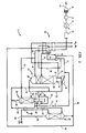
- an air separation plant 1 is illustrated that is designed to produce a high purity gaseous nitrogen product and an ultra-high purity liquid oxygen product. It should be pointed out that the present invention has equal applicability to a nitrogen generator that is designed to produce a lower purity nitrogen. Air is filtered in the filter 10 and is then compressed in a compressor 12. The heat of compression is removed by an aftercooler 14 and the thus cooled air is then initially processed in a pre-purification unit 16 to remove carbon dioxide and water vapour. The resulting air is cooled within a main heat exchanger 18 to a temperature suitable for its rectification.
- the air now in partially liquid state passes in a stream 20 into a distillation column 24 which separates the air into an oxygen-rich fraction which collects in a sump or bottom region 26 of distillation column 24 and a high-purity nitrogen-rich fraction which collects in a top region 28 of distillation column 24.
- a first head condenser 30 is connected to (and hence associated with) distillation column 24 so that a nitrogen-rich stream 32 composed of the nitrogen-rich fraction is condensed in indirect heat exchange with a coolant stream 33 that is formed by taking a stream 38 of the oxygen-rich fraction (or "crude oxygen") that has collected in sump 26 of distillation column 24, and expanding part of the stream through a valve 40.
- the expansion valve 40 is arranged to expand part of the crude oxygen stream 38 to a sufficiently low temperature to condense nitrogen-rich stream 32 within first head condenser 30.
- Resulting condensed nitrogen-rich stream 34 is introduced into top region 28 of distillation column 24 as reflux.
- Part of nitrogen-rich stream 32 can be extracted as a gaseous nitrogen product stream 36 which is warmed to approximately ambient temperature in main heat exchanger 18.
- a liquid nitrogen product stream may be taken from the condensed nitrogen-rich stream 34.
- high purity nitrogen as used herein means nitrogen having a purity of less than about 100 parts per billion oxygen by volume.
- a portion of vaporised coolant stream 42 flows from the condenser 30 and is recompressed within a recycle compressor 44 to the column pressure of distillation column 24.
- the recycle compressor is connected intermediate main heat exchanger 18 and first head condenser 30 so that a compressed crude oxygen stream 46 is cooled to a rectification temperature at which distillation column 24 operates.
- Distillation column 24 communicates with main heat exchanger 18 thereby enabling a part 47 of compressed crude oxygen stream 46 is introduced into bottom region 26 of distillation column 24.
- a rectification column 48 also communicates with main heat exchanger 18 to receive a first subsidiary stream 50 formed from a remaining part of compressed crude oxygen stream 46 downstream of the main heat exchanger 18.
- Rectification column 48 is configured to rectify crude oxygen contained within first subsidiary stream 50 in order to produce a substantially hydrocarbon-free head fraction and a bottom liquid fraction is concentrated in the hydrocarbons.
- first subsidiary stream 50 contains about 45% by volume of oxygen with the remainder being made up of nitrogen and argon and higher boiling impurities such as methane, krypton, and xenon. These higher boiling impurities have a concentration of approximately 10 parts per million within first subsidiary stream 50.
- the head vapour After rectification, the head vapour has a concentration of approximately 30% by volume of oxygen and less than 0.1 parts per billion by volume methane, about 1.5% by volume argon and the remainder nitrogen.
- a second subsidiary stream 52 is formed which is composed of a portion of crude oxygen stream 38.
- a second head condenser 54 is associated with rectification column 48 for receiving second subsidiary stream 52 and indirectly exchanging heat between second subsidiary stream 52 and a hydrocarbon-free stream 56, composed of the substantially hydrocarbon-free vapour fraction.
- Second head condenser 54 condenses hydrocarbon-free stream 56 and returns a part of the hydrocarbon-free stream 56 as a reflux stream 58 to rectification column 48.
- a stripping column 60 communicates with a second head condenser 54 to receive another part 62 of hydrocarbon-free stream 56, after the condensation thereof within second head condenser 54.
- the stripping column 60 is configured to strip argon and nitrogen from the part 62 of hydrocarbon-free stream 56 to produce ultra-high purity oxygen as a bottom fraction.
- An expansion valve 64 is interposed between stripping column 60 and second head condenser 54 and expands the part 62 of the hydrocarbon-free stream to a low pressure which facilitates separation of argon and nitrogen, together, from oxygen to produce the ultra-high purity liquid oxygen.
- a heat exchanger or reboiler 66 communicates with second head condenser 54 and with stripping column 60 and vaporises part of the ultra-high purity oxygen by indirect heat exchange with part of second subsidiary stream 52, downstream of the condensation of the hydrocarbon-free stream 56. This causes vaporisation of the ultra-high purity liquid oxygen to produce boil-up within stripping column 60 and condensation of the part of second subsidiary stream 52.
- a stream of the bottom liquid fraction of rectification column 48 and the part of the second subsidiary stream 52 are expanded through expansion valves 68 and 69, respectively, and are combined to form a combined stream 70.
- the combined stream 70 is at the pressure of crude oxygen stream 38 downstream of the valve 40 and is combined with the crude oxygen stream 38 downstream of the valve 40.
- second subsidiary stream 52 is required to boil ultra-high purity liquid oxygen within stripping column 60.
- a bypass stream 72 can be extracted from second subsidiary stream 52 downstream of second head condenser 54 and combined with coolant stream 33 (after vaporisation thereof) to form vaporised coolant stream 42.
- Pressure reduction is accomplished by means of an expansion valve 74. This is, however, optional and as such, all of second subsidiary stream 52 could be used to boil ultra-high purity liquid oxygen within stripping column 60.
- a third subsidiary stream 76 is formed from a further portion of vaporised coolant stream 42.
- Third subsidiary stream 76 is preferably partially warmed, that is warmed to a temperature between the cold and warm end temperatures of main heat exchanger 18, and is then expanded in a turboexpander 78 to produce the refrigeration.
- turboexpander 78 is coupled to recycle compressor 44 to use at least part of the work performed by the turboexpansion in driving the recycle compressor 44.
- vapour produced at the head of stripping column 60 which contains in the main, argon and nitrogen, can be combined with a resultant turboexpanded stream 80 to produce a waste nitrogen stream 82 which is warmed within main heat exchanger 18 to the temperature of the warm end of main heat exchanger 18.
- the resultant ultra-high purity liquid oxygen produced within stripping column 60 contains oxygen, less than about 3 parts per billion by volume of hydrocarbons such as methane, acetylene, propane and propylene, less than about 50 parts per billion by volume of argon and less than about 1 part per billion by volume of nitrogen.
- the ultra-high purity stream can be extracted as a product stream 84 from part of a recirculating boil-up stream 86 passing through heat exchanger 66 to provide boil-up for stripping column 60.
- all or part of the product stream could be vaporised either through a separate vaporiser or be withdrawn as a vapour from stripping column 60 and passed through main heat exchanger 18.
Landscapes
- Engineering & Computer Science (AREA)
- Physics & Mathematics (AREA)
- Mechanical Engineering (AREA)
- Thermal Sciences (AREA)
- General Engineering & Computer Science (AREA)
- Health & Medical Sciences (AREA)
- Emergency Medicine (AREA)
- Separation By Low-Temperature Treatments (AREA)
Applications Claiming Priority (2)
| Application Number | Priority Date | Filing Date | Title |
|---|---|---|---|
| US494899 | 1995-06-26 | ||
| US08/494,899 US5528906A (en) | 1995-06-26 | 1995-06-26 | Method and apparatus for producing ultra-high purity oxygen |
Publications (2)
| Publication Number | Publication Date |
|---|---|
| EP0751358A2 true EP0751358A2 (de) | 1997-01-02 |
| EP0751358A3 EP0751358A3 (de) | 1997-05-07 |
Family
ID=23966419
Family Applications (1)
| Application Number | Title | Priority Date | Filing Date |
|---|---|---|---|
| EP96304589A Withdrawn EP0751358A3 (de) | 1995-06-26 | 1996-06-20 | Verfahren und Vorrichtung zur Herstellung von ultrahochreinem Sauerstoff |
Country Status (11)
| Country | Link |
|---|---|
| US (1) | US5528906A (de) |
| EP (1) | EP0751358A3 (de) |
| JP (1) | JPH0914832A (de) |
| KR (1) | KR970002229A (de) |
| CN (1) | CN1158978A (de) |
| AU (1) | AU698037B2 (de) |
| CA (1) | CA2175775A1 (de) |
| IL (1) | IL118053A0 (de) |
| MY (1) | MY132272A (de) |
| SG (1) | SG38969A1 (de) |
| ZA (1) | ZA963791B (de) |
Families Citing this family (15)
| Publication number | Priority date | Publication date | Assignee | Title |
|---|---|---|---|---|
| GB9607200D0 (en) * | 1996-04-04 | 1996-06-12 | Boc Group Plc | Air separation |
| US5682765A (en) * | 1996-12-12 | 1997-11-04 | Praxair Technology, Inc. | Cryogenic rectification system for producing argon and lower purity oxygen |
| US5918482A (en) * | 1998-02-17 | 1999-07-06 | Praxair Technology, Inc. | Cryogenic rectification system for producing ultra-high purity nitrogen and ultra-high purity oxygen |
| DE19817794A1 (de) | 1998-04-21 | 1999-10-28 | Basf Ag | Hochreine wässrige Wasserstoffperoxid-Lösungen, Verfahren zu ihrer Herstellung und ihre Verwendung |
| US6279345B1 (en) | 2000-05-18 | 2001-08-28 | Praxair Technology, Inc. | Cryogenic air separation system with split kettle recycle |
| US6327873B1 (en) | 2000-06-14 | 2001-12-11 | Praxair Technology Inc. | Cryogenic rectification system for producing ultra high purity oxygen |
| US6397632B1 (en) * | 2001-07-11 | 2002-06-04 | Praxair Technology, Inc. | Gryogenic rectification method for increased argon production |
| US6460373B1 (en) | 2001-12-04 | 2002-10-08 | Praxair Technology, Inc. | Cryogenic rectification system for producing high purity oxygen |
| DE102007024168A1 (de) * | 2007-05-24 | 2008-11-27 | Linde Ag | Verfahren und Vorrichtung zur Tieftemperatur-Luftzerlegung |
| DE102007051183A1 (de) * | 2007-10-25 | 2009-04-30 | Linde Aktiengesellschaft | Verfahren zur Tieftemperatur-Luftzerlegung |
| DE102007051184A1 (de) * | 2007-10-25 | 2009-04-30 | Linde Aktiengesellschaft | Verfahren und Vorrichtung zur Tieftemperatur-Luftzerlegung |
| DE102008064117A1 (de) | 2008-12-19 | 2009-05-28 | Linde Ag | Verfahren und Vorrichtung zur Tieftemperaturzerlegung von Luft |
| EP2236964B1 (de) | 2009-03-24 | 2019-11-20 | Linde AG | Verfahren und Vorrichtung zur Tieftemperatur-Luftzerlegung |
| EP3870915A1 (de) * | 2018-10-23 | 2021-09-01 | Linde GmbH | Verfahren und anlage zur tieftemperaturzerlegung von luft |
| JP7355978B2 (ja) * | 2019-04-08 | 2023-10-04 | レール・リキード-ソシエテ・アノニム・プール・レテュード・エ・レクスプロワタシオン・デ・プロセデ・ジョルジュ・クロード | 深冷空気分離装置 |
Citations (4)
| Publication number | Priority date | Publication date | Assignee | Title |
|---|---|---|---|---|
| US4824453A (en) * | 1987-07-09 | 1989-04-25 | Linde Aktiengesellschaft | Process and apparatus for air separation by rectification |
| EP0376464A1 (de) * | 1988-12-02 | 1990-07-04 | The BOC Group plc | Lufttrennung |
| EP0377354A1 (de) * | 1988-11-29 | 1990-07-11 | Liquid Air Engineering Corporation | Reinigungsverfahren und Apparat für kryogenisches Gas |
| WO1993021488A1 (en) * | 1992-04-13 | 1993-10-28 | L'air Liquide, Societe Anonyme Pour L'etude Et L'exploitation Des Procedes Georges Claude | Ultra-high purity nitrogen and oxygen generator |
Family Cites Families (12)
| Publication number | Priority date | Publication date | Assignee | Title |
|---|---|---|---|---|
| JPS6124967A (ja) * | 1984-07-13 | 1986-02-03 | 大同酸素株式会社 | 高純度窒素ガス製造装置 |
| US4560397A (en) * | 1984-08-16 | 1985-12-24 | Union Carbide Corporation | Process to produce ultrahigh purity oxygen |
| US4615716A (en) * | 1985-08-27 | 1986-10-07 | Air Products And Chemicals, Inc. | Process for producing ultra high purity oxygen |
| US4783210A (en) * | 1987-12-14 | 1988-11-08 | Air Products And Chemicals, Inc. | Air separation process with modified single distillation column nitrogen generator |
| US4869741A (en) * | 1988-05-13 | 1989-09-26 | Air Products And Chemicals, Inc. | Ultra pure liquid oxygen cycle |
| JPH0672740B2 (ja) * | 1989-01-20 | 1994-09-14 | ル・エール・リクイツド・ソシエテ・アノニム・プール・ル・エチユド・エ・ル・エクスプルワテション・デ・プロセデ・ジエオルジエ・クロード | 空気分離及び超高純度酸素製造方法並びに装置 |
| US5049173A (en) * | 1990-03-06 | 1991-09-17 | Air Products And Chemicals, Inc. | Production of ultra-high purity oxygen from cryogenic air separation plants |
| US5133790A (en) * | 1991-06-24 | 1992-07-28 | Union Carbide Industrial Gases Technology Corporation | Cryogenic rectification method for producing refined argon |
| US5235816A (en) * | 1991-10-10 | 1993-08-17 | Praxair Technology, Inc. | Cryogenic rectification system for producing high purity oxygen |
| US5218825A (en) * | 1991-11-15 | 1993-06-15 | Air Products And Chemicals, Inc. | Coproduction of a normal purity and ultra high purity volatile component from a multi-component stream |
| US5228296A (en) * | 1992-02-27 | 1993-07-20 | Praxair Technology, Inc. | Cryogenic rectification system with argon heat pump |
| US5195324A (en) * | 1992-03-19 | 1993-03-23 | Prazair Technology, Inc. | Cryogenic rectification system for producing nitrogen and ultra high purity oxygen |
-
1995
- 1995-06-26 US US08/494,899 patent/US5528906A/en not_active Expired - Fee Related
-
1996
- 1996-04-26 IL IL11805396A patent/IL118053A0/xx unknown
- 1996-04-26 AU AU50899/96A patent/AU698037B2/en not_active Ceased
- 1996-05-03 CA CA002175775A patent/CA2175775A1/en not_active Abandoned
- 1996-05-13 SG SG1996009782A patent/SG38969A1/en unknown
- 1996-05-13 ZA ZA963791A patent/ZA963791B/xx unknown
- 1996-06-20 EP EP96304589A patent/EP0751358A3/de not_active Withdrawn
- 1996-06-24 JP JP8162708A patent/JPH0914832A/ja active Pending
- 1996-06-25 KR KR1019960023575A patent/KR970002229A/ko active IP Right Grant
- 1996-06-26 MY MYPI96002592A patent/MY132272A/en unknown
- 1996-06-26 CN CN96106926A patent/CN1158978A/zh active Pending
Patent Citations (4)
| Publication number | Priority date | Publication date | Assignee | Title |
|---|---|---|---|---|
| US4824453A (en) * | 1987-07-09 | 1989-04-25 | Linde Aktiengesellschaft | Process and apparatus for air separation by rectification |
| EP0377354A1 (de) * | 1988-11-29 | 1990-07-11 | Liquid Air Engineering Corporation | Reinigungsverfahren und Apparat für kryogenisches Gas |
| EP0376464A1 (de) * | 1988-12-02 | 1990-07-04 | The BOC Group plc | Lufttrennung |
| WO1993021488A1 (en) * | 1992-04-13 | 1993-10-28 | L'air Liquide, Societe Anonyme Pour L'etude Et L'exploitation Des Procedes Georges Claude | Ultra-high purity nitrogen and oxygen generator |
Also Published As
| Publication number | Publication date |
|---|---|
| CN1158978A (zh) | 1997-09-10 |
| AU5089996A (en) | 1997-01-09 |
| AU698037B2 (en) | 1998-10-22 |
| ZA963791B (en) | 1996-09-05 |
| MY132272A (en) | 2007-09-28 |
| EP0751358A3 (de) | 1997-05-07 |
| KR970002229A (ko) | 1997-01-24 |
| CA2175775A1 (en) | 1996-12-27 |
| US5528906A (en) | 1996-06-25 |
| IL118053A0 (en) | 1996-08-04 |
| JPH0914832A (ja) | 1997-01-17 |
| SG38969A1 (en) | 1997-04-17 |
Similar Documents
| Publication | Publication Date | Title |
|---|---|---|
| US4704148A (en) | Cycle to produce low purity oxygen | |
| US5454227A (en) | Air separation method and apparatus | |
| US4702757A (en) | Dual air pressure cycle to produce low purity oxygen | |
| US4783210A (en) | Air separation process with modified single distillation column nitrogen generator | |
| JP2836781B2 (ja) | 空気分離方法 | |
| US5582034A (en) | Air separation method and apparatus for producing nitrogen | |
| EP0751358A2 (de) | Verfahren und Vorrichtung zur Herstellung von ultrahochreinem Sauerstoff | |
| AU680472B2 (en) | Single column process and apparatus for producing oxygen at above atmospheric pressure | |
| US5170630A (en) | Process and apparatus for producing nitrogen of ultra-high purity | |
| EP0780648A2 (de) | Verfahren und Vorrichtung zur Stickstofferzeugung | |
| EP0807792B1 (de) | Verfahren und Vorrichtung zur Lufttrennung | |
| US5682762A (en) | Process to produce high pressure nitrogen using a high pressure column and one or more lower pressure columns | |
| EP0997694A2 (de) | Verfahren und Vorrichtung zur Luftzerleggung zur Sauerstoffsherstellung | |
| AU706680B2 (en) | Air separation | |
| EP0615105B1 (de) | Luftzerlegung | |
| EP0932004A2 (de) | Vorrichtung zur Herstellung von Stickstoff | |
| EP1050730A1 (de) | Luftzerlegung | |
| JPH11325717A (ja) | 空気の分離 | |
| EP0952417A2 (de) | Lufttrennung | |
| KR0168707B1 (ko) | 질소의 제조를 위한 공기 분리 방법 및 장치 | |
| MXPA97003268A (en) | Method and separation apparatus of a |
Legal Events
| Date | Code | Title | Description |
|---|---|---|---|
| PUAI | Public reference made under article 153(3) epc to a published international application that has entered the european phase |
Free format text: ORIGINAL CODE: 0009012 |
|
| AK | Designated contracting states |
Kind code of ref document: A2 Designated state(s): BE DE FR GB IE IT NL SE |
|
| PUAL | Search report despatched |
Free format text: ORIGINAL CODE: 0009013 |
|
| AK | Designated contracting states |
Kind code of ref document: A3 Designated state(s): BE DE FR GB IE IT NL SE |
|
| 17P | Request for examination filed |
Effective date: 19971001 |
|
| STAA | Information on the status of an ep patent application or granted ep patent |
Free format text: STATUS: THE APPLICATION IS DEEMED TO BE WITHDRAWN |
|
| 18D | Application deemed to be withdrawn |
Effective date: 19990101 |