EP0751097A2 - Wasserbehandlungssystem - Google Patents
Wasserbehandlungssystem Download PDFInfo
- Publication number
- EP0751097A2 EP0751097A2 EP96304646A EP96304646A EP0751097A2 EP 0751097 A2 EP0751097 A2 EP 0751097A2 EP 96304646 A EP96304646 A EP 96304646A EP 96304646 A EP96304646 A EP 96304646A EP 0751097 A2 EP0751097 A2 EP 0751097A2
- Authority
- EP
- European Patent Office
- Prior art keywords
- water
- main
- bypass
- flow
- delivery means
- Prior art date
- Legal status (The legal status is an assumption and is not a legal conclusion. Google has not performed a legal analysis and makes no representation as to the accuracy of the status listed.)
- Withdrawn
Links
- XLYOFNOQVPJJNP-UHFFFAOYSA-N water Substances O XLYOFNOQVPJJNP-UHFFFAOYSA-N 0.000 title claims abstract description 102
- 239000000126 substance Substances 0.000 claims abstract description 59
- 238000000034 method Methods 0.000 claims abstract description 12
- 238000004891 communication Methods 0.000 claims abstract description 11
- 239000012530 fluid Substances 0.000 claims abstract description 11
- 238000011144 upstream manufacturing Methods 0.000 claims description 23
- 238000005086 pumping Methods 0.000 claims description 2
- 238000005070 sampling Methods 0.000 claims 2
- 230000009182 swimming Effects 0.000 description 10
- 238000005660 chlorination reaction Methods 0.000 description 9
- ZAMOUSCENKQFHK-UHFFFAOYSA-N Chlorine atom Chemical compound [Cl] ZAMOUSCENKQFHK-UHFFFAOYSA-N 0.000 description 4
- 239000000460 chlorine Substances 0.000 description 4
- 229910052801 chlorine Inorganic materials 0.000 description 4
- 238000010586 diagram Methods 0.000 description 3
- 238000002955 isolation Methods 0.000 description 3
- ZKQDCIXGCQPQNV-UHFFFAOYSA-N Calcium hypochlorite Chemical compound [Ca+2].Cl[O-].Cl[O-] ZKQDCIXGCQPQNV-UHFFFAOYSA-N 0.000 description 2
- 238000012423 maintenance Methods 0.000 description 2
- OYPRJOBELJOOCE-UHFFFAOYSA-N Calcium Chemical compound [Ca] OYPRJOBELJOOCE-UHFFFAOYSA-N 0.000 description 1
- 239000011575 calcium Substances 0.000 description 1
- 229910052791 calcium Inorganic materials 0.000 description 1
- 238000010276 construction Methods 0.000 description 1
- 230000001419 dependent effect Effects 0.000 description 1
- 230000003628 erosive effect Effects 0.000 description 1
- 230000005484 gravity Effects 0.000 description 1
- 231100001261 hazardous Toxicity 0.000 description 1
- 238000009434 installation Methods 0.000 description 1
- 230000007257 malfunction Effects 0.000 description 1
- 239000002245 particle Substances 0.000 description 1
- 230000002035 prolonged effect Effects 0.000 description 1
- 238000009877 rendering Methods 0.000 description 1
- 230000000284 resting effect Effects 0.000 description 1
- 229920006395 saturated elastomer Polymers 0.000 description 1
- 238000004062 sedimentation Methods 0.000 description 1
Images
Classifications
-
- C—CHEMISTRY; METALLURGY
- C02—TREATMENT OF WATER, WASTE WATER, SEWAGE, OR SLUDGE
- C02F—TREATMENT OF WATER, WASTE WATER, SEWAGE, OR SLUDGE
- C02F1/00—Treatment of water, waste water, or sewage
- C02F1/68—Treatment of water, waste water, or sewage by addition of specified substances, e.g. trace elements, for ameliorating potable water
- C02F1/685—Devices for dosing the additives
- C02F1/688—Devices in which the water progressively dissolves a solid compound
-
- G—PHYSICS
- G05—CONTROLLING; REGULATING
- G05D—SYSTEMS FOR CONTROLLING OR REGULATING NON-ELECTRIC VARIABLES
- G05D11/00—Control of flow ratio
- G05D11/02—Controlling ratio of two or more flows of fluid or fluent material
- G05D11/13—Controlling ratio of two or more flows of fluid or fluent material characterised by the use of electric means
- G05D11/135—Controlling ratio of two or more flows of fluid or fluent material characterised by the use of electric means by sensing at least one property of the mixture
- G05D11/138—Controlling ratio of two or more flows of fluid or fluent material characterised by the use of electric means by sensing at least one property of the mixture by sensing the concentration of the mixture, e.g. measuring pH value
Definitions
- This invention relates to a water treatment system, for example a water treatment system for introducing chemical into a swimming pool.
- swimming pools are normally treated by a chlorine donor.
- Calcium hypochlorite is a typical source of chlorine and this is normally available in granular form.
- calcium hypochlorite has an inherent characteristic of forming scale, blockage and sedimentation which has caused other types of treatment systems to malfunction.
- a typical system is disclosed in US-A-4732689.
- This system comprises two vertical feeder tubes containing chemical tablets, extending into a bath.
- the bath receives water from a main via an inlet branch pipe.
- the bath includes a linear weir, thus rendering the level of water in the bath directly proportional to the flow of water into the bath.
- Vertical slots extend from the lower end of each of the feeder tubes, thus exposing the tablets to the water. Thus the area of tablet exposed to water is directly proportional to the flow rate of water through the system.
- the linear weir of this device is a precision engineered component, and the system is entirely dependent on flow rate.
- the device also relies on there being sufficient chemical tablets in the feeders that the stacks extend above the water surface in the bath for the entire range of the level of the surface. Thus a large quantity of chemical must be stocked.
- US-A-4584106 discloses a chlorination system for chlorinating a hot tub or spa and comprise a main tube defining a flow path to the tub and a chlorination unit including a feeder tube connected to and in parallel with the main tube having a chlorination chamber in which flow through the feeder tube is exposed to chlorination tablets. Positioned upstream and downstream of the chlorination chambers are baffles which serve to regulate flow and to prevent large particles of the chlorination tablets from escaping into the flow path.
- the feeder tube forms a loop from the main flow path extending from the downstream (high pressure) side of a main circulating pump to the upstream (low pressure) side of the main circulating pump connected by inlet and outlet venturis.
- a control valve is provided in the feeder loop upstream of the chlorination unit which controls the flow of water and thus regulates the concentration of the treatment chemicals present in the pool water. In order to prevent the introduction of chemical completely, the control valve is used to close the feeder loop.
- An object of the present invention is to provide an improved water treatment system.
- the invention therefore includes a method of treating water passing through a main, the method comprising providing a bypass including chemical delivery means, a bypass inlet and a bypass outlet in fluid communication with the main, and valve means for selectively interrupting flow of water to the chemical delivery means, passing water from the main through said bypass to dose said water at the chemical delivery means, passing said dosed water back to the main, selectively interrupting the flow of water to the chemical delivery means, and evacuating water from the chemical delivery means whilst the flow of water is interrupted.
- the method further comprises providing a constriction in fluid communication with the main and the bypass outlet, and by means of the constriction drawing water through the bypass.
- a water treatment system comprising a main, a main inlet for receiving water into the system, a main outlet for delivering water from the system, a main pump for pumping water from the main inlet to the main outlet, and a bypass including chemical delivery means, said bypass including a bypass inlet and a bypass outlet in fluid communication with the main, the system further comprising means to draw water from said chemical delivery means and means for selectively interrupting flow of water to the chemical delivery means, such that on interruption of said flow, water is substantially removed from said delivery means.
- the means for selectively interrupting flow of water may be valve means.
- the valve means may be a manually operable valve or an automatic control valve operative according to the concentration of chemical in the water in the main.
- the system further comprises a constriction in fluid communication with the main and with the bypass outlet, the constriction being arranged to exert suction on the bypass outlet to draw water through the bypass in use.
- the constriction is a venturi type constriction, the bypass outlet entering the constriction at the throat of the venturi.
- the bypass may include a control valve situated upstream of the chemical delivery means.
- the control valve is operable to regulate flow through the chemical delivery means in order to regulate chemical delivery. If the control valve is shut off, water is drawn away from the chemical delivery means thus avoiding prolonged contact of the chemical delivery means with water.
- the main pump is preferably situated between the main inlet and the main outlet.
- the bypass inlet may be in fluid communication with the main downstream of said pump.
- a secondary branch may be provided, having an inlet and an outlet both in fluid communication with the main, the inlet being situated upstream of the outlet in the main, the constriction being situated in the secondary branch.
- the inlet and outlet of the branch are preferably situated downstream of the main pump.
- the main may include devices such as a filter or a heater, preferably downstream of the main pump.
- devices such as a filter or a heater, preferably downstream of the main pump.
- the inlet of the secondary branch is upstream of such devices, and the outlet of the secondary branch is downstream of such devices.
- the secondary branch is advantageous in cases where pressure upstream of the main pump is relatively high, such as where the system is arranged to receive, treat and discharge water of a swimming pool and the system is situated a considerable depth below the pool.
- a secondary pump may be provided in the secondary branch between the inlet of the secondary branch and the constriction to improve the effectiveness of the constriction.
- Isolating valves may be provided upstream and downstream of the chemical delivery means in the bypass to prevent flow of water in the bypass. This allows maintenance operations to be performed on the chemical delivery means without shutting down the entire system.
- Isolating valves may be provided in the secondary branch for maintenance purposes.
- the chemical delivery means is a feeder device comprising a body defining a flow path therethrough, a tablet tube opening into the flow path retaining a supply of chemical to be exposed to erosion by water caused to flow along the flow path, and shield means for partially shielding the chemical with respect to the flow of water.
- the shield means may be movable to regulate the degree of exposure of the chemical to the flow of pool water.
- the shield means comprises a portion of the tablet tube extending into the flow path, and the tablet tube further includes interengaging means on the tablet tube and on the body whereby the tablet tube is movably engaged with the body, in use movement of the tablet tube in a direction transverse to the flow of water moving the shield means with respect to the chemical thereby exposing more or less chemical according to the direction of movement.
- the interengaging means may comprise cooperable screw threads on the tablet tube and body.
- the tablet tube is preferably threadingly engaged with the body whereby, screwing or unscrewing the tablet tube will determine the amount of chemical exposed to the flow of pool water.
- the chemical is in tablet form.
- the tablet may be gravity fed or may be biassed into position in the flow tube by suitable spring means.
- a platform may be disposed opposite the tablet tube on which the lowermost tablet rests in use. If desired, more than one tablet tube may open into the flow path.
- the system may include sample means adapted to sample the concentration of the chemical in the main for control of said feeder device, and which said feeder device is arranged to return said flow to said main downstream of said sample means.
- the sample means may be arranged to receive the flow of water downstream of the main pump and to return said flow upstream of said pump.
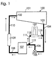
- Figure 1 illustrates a first water treatment system 100 for a swimming pool 101 provided with an inlet 102 and an outlet 103.
- An outlet pipe 104 extends from the outlet 103 to an inlet of a main circulating pump 105.
- An outlet of the pump 105 is connected via a first main pipe 106 to an inlet of a filter 107.
- a second main pipe 108 extends from an outlet of the filter 107 to an inlet of a water heater 109.
- a third main pipe 110 extends from an outlet of the water heater 109 to the inlet 102 of the swimming pool 100, completing the main flow circuit.
- a branch pipe 111 branches from the first main pipe 106 and rejoins the main flow circuit by connecting to the outlet pipe 104.
- the first branch pipe 111 includes, in series from upstream to downstream, a first isolating valve 113, a control valve 118, a feeder device 150 and a second isolating valve 116.
- the embodiment of the invention is effective when the system is to be installed above or level with the swimming pool 101.
- the pressure in the outlet pipe 104 is sufficiently low that on closure of the control valve 118 or the first isolating valve 113, water is drawn out of the feeder device 150 by the pressure differential and the action of the main pump 105.
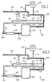
- Figure 2 illustrates schematically a second water treatment system 130 for the swimming pool 101 (not shown).
- the second system includes a main flow circuit as described with reference to figure 1 and the same reference numerals have been used for corresponding parts.
- a first branch pipe 112 branches from the first main pipe 106 and rejoins the main flow circuit by connecting to the outlet pipe 110.
- the first branch pipe 112 includes, in series from upstream to downstream, a first isolating valve 113, a venturi 115 and a second isolating valve 116.
- a second branch pipe 117 is connected at its upstream end to first main pipe 106 upstream of the connection of the first branch pipe 112 to the first main pipe 106.
- the second branch pipe 117 includes, in series from upstream to downstream, a first isolation valve 131, the control valve 118 as previously described, a feeder device 180 and a second isolation valve 132.
- the feeder device 180 is of similar construction to feeder device 150 of the first system; the differences between the two feeder devices 150, 180 will be described below.
- a sample cell feeder pipe 133 extends from the first main pipe 106 upstream of the connection of the second branch pipe 117 to the first main pipe 106.
- the sample cell feeder pipe 133 extends to the inlet of a sample cell 134 which is operative to measure chemical concentrations.
- Control equipment (not shown) may be used to process the results obtained by the sample cell 134 to control the control valve 118 in response to changes in chemical concentration.
- a sample cell outlet pipe 135 extends from the sample cell 134 and connects to the outlet pipe 104. Thus a sample loop is formed, water being driven around the loop by the action of the pump 105.
- FIG 3 illustrates schematically a third water treatment system 140 for the swimming pool 101 (not shown) including a main flow circuit; first branch pipe 112, second branch pipe 117 and sample loop as described with reference to the second system 130. Additionally, a booster pump 114 as described with reference to the first system 100 is provided in the first branch pipe 112.
- the third system 140 is particularly effective when the system is situated a considerable depth below the water level of the swimming pool.
- the booster pump increases the effectiveness of the venturi 115, which is extremely important because of the high pressure which will be encountered upstream of the main pump 105 and the feeder device 180.
- the second system 130 is effective when installed moderately below the swimming pool water level. It is cheaper than the third system, both in apparatus and installation costs as only one pump need be provided.
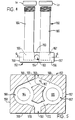
- FIGs 4 and 5 illustrate the feeder device 150 shown schematically in figure 1 except that in figure 1 the feeder tubes are shown aligned for simplicity.
- the feeder device 150 comprises a flat rectangular body 152 including upper and lower faces 153, 154, upstream and downstream faces 155, 156 and side faces 157, 158.
- An inlet bore 160 of circular cross section extends from the centre of the upstream face 155, within the body 152.
- An auxiliary inlet bore 162 extends from the upper face 153, proximate the edge adjoining the upstream face 155, and joins the inlet bore 160.
- An outlet bore 163 extends within the body 152 from the downstream face 156 coaxially with the inlet bore 160.
- Two feeder tubes 164, 165 extend perpendicularly with respect to the upper face 153, and are arranged symmetrically about the axis of the inlet bore 160 and the outlet bore 163.
- the feeder tubes 164, 165 threadingly extend within the body 152 to respective tablet dissolving chambers 166, 167.
- each feeder tube 164, 165 is closed by a screw cap 21 sealed to the feeder tube 164, 165 by an O-ring (not shown).
- the feeder tubes 164, 165 are provided in use with one or more pool chemical tablets, known as DURATION (Registered Trade Mark).
- Each tablet dissolving chamber is cylindrical and coaxial with the respective feeder tube, a chemical tablet in use emerging from the feeder tube and resting on the floor on the tablet dissolving chamber. By rotating the feeder tubes 164, 165 the amount of chemical exposed to the flow of water may be adjusted.
- the inlet bore 160 splits into two inlet branches 168, 169 each of which extends to a respective tablet dissolving chamber.
- Each tablet dissolving chamber has an outlet branch 170, 172, which join and form the outlet bore 163.
- the feeder device 150 is located so as to introduce treated water downstream of the sample cell, since introduction of chemical upstream of the sample cell would otherwise provide a false reading.
- the removable cap 21 allows chemicals to be replenished after first isolating the feeder device 150 by closing both isolation valves.
- the feeder device 150 is totally variable by either:
- the feeder device 180 of Figures 2 and 3 is similar to the feeder device of Figure 1. However, the device has only one feeder tube and consequently only one tablet dissolving chamber.
- the cap 21 of the feeder tube may incorporate an air vent (not shown).
- the water level should rise up the feeder tube no higher than half of one tablet.
- the chlorine output can be increased slightly by allowing the water level to rise higher up the feeder tubes.
- This level can be adjusted by manipulation of the inlet/outlet valves and the air vent. It should be noted that this will increase the calcium build up on the inside of the tubes and, if the feeder tubes are transparent, will in time obscure the view of the tablets within the tubes.
- the pressure must be raised to atmospheric pressure. This is achieved by adjusting the air vent and outlet isolating valve to create a slight back pressure.
Landscapes
- Engineering & Computer Science (AREA)
- Chemical & Material Sciences (AREA)
- Organic Chemistry (AREA)
- Physics & Mathematics (AREA)
- Hydrology & Water Resources (AREA)
- Medicinal Chemistry (AREA)
- Environmental & Geological Engineering (AREA)
- Water Supply & Treatment (AREA)
- Health & Medical Sciences (AREA)
- Life Sciences & Earth Sciences (AREA)
- General Physics & Mathematics (AREA)
- Automation & Control Theory (AREA)
- Treatment Of Water By Oxidation Or Reduction (AREA)
- Separation Using Semi-Permeable Membranes (AREA)
- Water Treatment By Sorption (AREA)
- Treatment Of Water By Ion Exchange (AREA)
Applications Claiming Priority (2)
| Application Number | Priority Date | Filing Date | Title |
|---|---|---|---|
| GB9513106 | 1995-06-27 | ||
| GBGB9513106.6A GB9513106D0 (en) | 1995-06-27 | 1995-06-27 | Water treatment system |
Publications (2)
| Publication Number | Publication Date |
|---|---|
| EP0751097A2 true EP0751097A2 (de) | 1997-01-02 |
| EP0751097A3 EP0751097A3 (de) | 1998-04-08 |
Family
ID=10776763
Family Applications (1)
| Application Number | Title | Priority Date | Filing Date |
|---|---|---|---|
| EP96304646A Withdrawn EP0751097A3 (de) | 1995-06-27 | 1996-06-24 | Wasserbehandlungssystem |
Country Status (2)
| Country | Link |
|---|---|
| EP (1) | EP0751097A3 (de) |
| GB (1) | GB9513106D0 (de) |
Cited By (4)
| Publication number | Priority date | Publication date | Assignee | Title |
|---|---|---|---|---|
| FR2809330A1 (fr) * | 2000-05-26 | 2001-11-30 | Inst Francais Du Petrole | Dispositif de dosage d'un reactif par dissolution dans un ecoulement de liquide |
| US8114298B2 (en) | 2006-08-03 | 2012-02-14 | Bromine Compounds Ltd. | Method, device and system for water treatment |
| CN104768879A (zh) * | 2012-11-16 | 2015-07-08 | 荷兰联合利华有限公司 | 膳食补充剂配给装置 |
| CN110510717A (zh) * | 2019-08-22 | 2019-11-29 | 广州腾龙电子塑胶科技有限公司 | 一种投药器 |
Family Cites Families (5)
| Publication number | Priority date | Publication date | Assignee | Title |
|---|---|---|---|---|
| US3710817A (en) * | 1970-02-03 | 1973-01-16 | Anzen Prod | Multiple solutes additive apparatus |
| US3867290A (en) * | 1973-06-04 | 1975-02-18 | Charles A Mackey | Apparatus for chemical treatment of swimming pools |
| US5066408A (en) * | 1990-03-15 | 1991-11-19 | Powell Jonathan S | Means and method to treat swimming pool water |
| US5133381A (en) * | 1990-10-29 | 1992-07-28 | Olin Corporation | Dual range periodic chemical dispenser for swimming pools |
| GB9326448D0 (en) * | 1993-12-24 | 1994-02-23 | Olin Uk Limited | Feeder device |
-
1995
- 1995-06-27 GB GBGB9513106.6A patent/GB9513106D0/en active Pending
-
1996
- 1996-06-24 EP EP96304646A patent/EP0751097A3/de not_active Withdrawn
Cited By (6)
| Publication number | Priority date | Publication date | Assignee | Title |
|---|---|---|---|---|
| FR2809330A1 (fr) * | 2000-05-26 | 2001-11-30 | Inst Francais Du Petrole | Dispositif de dosage d'un reactif par dissolution dans un ecoulement de liquide |
| WO2001092164A1 (fr) * | 2000-05-26 | 2001-12-06 | Institut Francais Du Petrole | Dispositif de dosage d'un reactif par dissolution dans un ecoulement de liquide |
| US8114298B2 (en) | 2006-08-03 | 2012-02-14 | Bromine Compounds Ltd. | Method, device and system for water treatment |
| CN104768879A (zh) * | 2012-11-16 | 2015-07-08 | 荷兰联合利华有限公司 | 膳食补充剂配给装置 |
| US9668508B2 (en) | 2012-11-16 | 2017-06-06 | Conopco, Inc. | Dietary supplement dosing device |
| CN110510717A (zh) * | 2019-08-22 | 2019-11-29 | 广州腾龙电子塑胶科技有限公司 | 一种投药器 |
Also Published As
| Publication number | Publication date |
|---|---|
| GB9513106D0 (en) | 1995-08-30 |
| EP0751097A3 (de) | 1998-04-08 |
Similar Documents
| Publication | Publication Date | Title |
|---|---|---|
| US5213694A (en) | Water treatment control system for treating cooling tower makeup water | |
| KR101899564B1 (ko) | 차아염소산나트륨 주입시스템 | |
| US5089127A (en) | Chemical feed apparatus | |
| CA1330549C (en) | Pool chemical dispenser | |
| KR100494971B1 (ko) | 유체 이송 시스템, 및 유체 공급 탱크로부터 유체 유출 라인으로 유체를 이송하는 방법 | |
| US3672508A (en) | Swimming pool chlorinator apparatus | |
| CN103347820B (zh) | 水处理系统 | |
| US6932912B2 (en) | Wastewater treatment system for residential septic systems | |
| EP2884190B1 (de) | Verfahren und Vorrichtung zur Entgasung eines Mediums in einem Kreislauf | |
| EP0751097A2 (de) | Wasserbehandlungssystem | |
| US3727632A (en) | Automatic chlorinator, plunger selector type | |
| EP0659956A1 (de) | Zuführvorrichtung | |
| US6048134A (en) | Automatic aspirator air control system | |
| JPS5852215B2 (ja) | 写真材料の現像装置 | |
| US4040962A (en) | Apparatus for feeding chemicals to a liquid stream | |
| CN105905962A (zh) | 一种cod稳定达标排放装置 | |
| US20040050798A1 (en) | Method and apparatus for ozone disinfection of liquid-carrying conduits | |
| CN204474384U (zh) | 一种污水处理系统的新型加氯装置 | |
| CN210915629U (zh) | 一种实验室离子型废液处理装置 | |
| CN116730457B (zh) | 一种污水处理剂播撒装置 | |
| RU2094388C1 (ru) | Хлоратор | |
| KR200267305Y1 (ko) | 자동 염소 투입기의 인젝터 | |
| US4946140A (en) | System for automatically feeding chemical liquids to cooling towers | |
| JP4744289B2 (ja) | 水質測定装置 | |
| CA1334611C (en) | Sewage flushing apparatus |
Legal Events
| Date | Code | Title | Description |
|---|---|---|---|
| PUAI | Public reference made under article 153(3) epc to a published international application that has entered the european phase |
Free format text: ORIGINAL CODE: 0009012 |
|
| AK | Designated contracting states |
Kind code of ref document: A2 Designated state(s): AT DE FR GB IE SE |
|
| PUAL | Search report despatched |
Free format text: ORIGINAL CODE: 0009013 |
|
| AK | Designated contracting states |
Kind code of ref document: A3 Designated state(s): AT DE FR GB IE SE |
|
| 17P | Request for examination filed |
Effective date: 19980619 |
|
| 17Q | First examination report despatched |
Effective date: 19980929 |
|
| RAP1 | Party data changed (applicant data changed or rights of an application transferred) |
Owner name: ARCH CHEMICALS LIMITED |
|
| STAA | Information on the status of an ep patent application or granted ep patent |
Free format text: STATUS: THE APPLICATION HAS BEEN WITHDRAWN |
|
| 18W | Application withdrawn |
Withdrawal date: 20020108 |