EP0750184A2 - Method and apparatus for diagnosing a multi-cylinder internal combustion engine - Google Patents
Method and apparatus for diagnosing a multi-cylinder internal combustion engine Download PDFInfo
- Publication number
- EP0750184A2 EP0750184A2 EP96890107A EP96890107A EP0750184A2 EP 0750184 A2 EP0750184 A2 EP 0750184A2 EP 96890107 A EP96890107 A EP 96890107A EP 96890107 A EP96890107 A EP 96890107A EP 0750184 A2 EP0750184 A2 EP 0750184A2
- Authority
- EP
- European Patent Office
- Prior art keywords
- internal combustion
- cylinder
- combustion engine
- diagnostic
- diagnostic method
- Prior art date
- Legal status (The legal status is an assumption and is not a legal conclusion. Google has not performed a legal analysis and makes no representation as to the accuracy of the status listed.)
- Granted
Links
Images


Classifications
-
- G—PHYSICS
- G01—MEASURING; TESTING
- G01M—TESTING STATIC OR DYNAMIC BALANCE OF MACHINES OR STRUCTURES; TESTING OF STRUCTURES OR APPARATUS, NOT OTHERWISE PROVIDED FOR
- G01M15/00—Testing of engines
- G01M15/04—Testing internal-combustion engines
- G01M15/042—Testing internal-combustion engines by monitoring a single specific parameter not covered by groups G01M15/06 - G01M15/12
- G01M15/046—Testing internal-combustion engines by monitoring a single specific parameter not covered by groups G01M15/06 - G01M15/12 by monitoring revolutions
-
- F—MECHANICAL ENGINEERING; LIGHTING; HEATING; WEAPONS; BLASTING
- F02—COMBUSTION ENGINES; HOT-GAS OR COMBUSTION-PRODUCT ENGINE PLANTS
- F02D—CONTROLLING COMBUSTION ENGINES
- F02D2200/00—Input parameters for engine control
- F02D2200/02—Input parameters for engine control the parameters being related to the engine
- F02D2200/10—Parameters related to the engine output, e.g. engine torque or engine speed
- F02D2200/1015—Engines misfires
Definitions
- the invention relates to a diagnostic method for multi-cylinder internal combustion engines, wherein angular velocities are recorded for at least one crank-driven component of the internal combustion engine for defined crank angle positions, and from this, taking into account the respectively effective total moment of inertia, the respective total energies or diagnostic parameters represented thereby, such as in particular single-cylinder power quantities or single-cylinder load variables, be determined. Furthermore, the invention also relates to a method for the initial adjustment or for the adjustment if necessary of an internal combustion engine checked by means of such a diagnostic method.
- the invention also relates to a device for diagnosing multi-cylinder internal combustion engines, with at least one measuring unit for determining angular velocities on a crank-driven component of the internal combustion engine and an associated evaluation unit, in which, taking into account crank angle-dependent total moments of inertia, diagnostic parameters, such as, in particular, single-cylinder power parameters or Single cylinder load sizes can be determined.
- EP-A-0 434 665 it is known to determine a single cylinder power measure based on one or more angular velocity profiles (at several locations on the shaft train) using the so-called energy level method from the profile of the stored kinetic energy.
- the influence of the mass force and the influence of torsional vibrations are taken into account and, on the other hand, a so-called mixed effective mean pressure is calculated as a measurement, which allows small changes in individual cylinder power values to be recognized and not just the total failure of a cylinder, for example.
- the disadvantage is that only those torsional vibrations can be compensated for that run within the intended system limits.
- the object of the present invention is to improve methods and devices of the type mentioned at the outset in such a way that the disadvantages mentioned of the known methods and devices are avoided and in particular, for example, that the accuracy of the diagnostic parameters determined for the single-cylinder evaluation can be increased in such a way that not only misfire detection, but also a direct control of the amount of fuel supplied to the individual cylinders is made possible.
- This task is also to be solved not only at idling but also at all engine speeds, particularly in the full-load range, which is particularly advantageous, for example, in diesel internal combustion engines, which with full load minimal excess air can be operated. If this minimum air excess value in individual cylinders is undershot, the undesirable emission of pollutants increases disproportionately.
- the stated object is achieved in a diagnostic method of the type mentioned at the outset in that, in addition to the angular velocity measurement (s), at least one rotational angle or time-resolved torque measurement is carried out on an output-side system boundary and the respective energy transport represented thereby System limit is taken into account when determining the diagnostic parameters.
- the device according to the invention for diagnosing multi-cylinder internal combustion engines is accordingly characterized in that at least one further measuring unit for measuring the angle of rotation or time-resolved torque is provided on a system boundary on the output side and is likewise connected to the evaluation unit.
- the additional instantaneous measurement - preferably according to the flywheel of the internal combustion engine - makes the associated instantaneous Energy transport recorded over this system boundary and billed. This advantageously makes one directly independent of the assumption that the torque on the flywheel is periodic in the ignition interval. This is not the case if, e.g. Torsional vibrations occur in the drive train, or feedback effects from an uneven roadway or the like require a strongly fluctuating torque from the internal combustion engine.
- the invention thus represents an essential improvement or generalization of the above-mentioned "energy level method".
- This is versatile - and not only usable for single-cylinder power measurement
- the calculation of the energy currently stored in the respective system is improved by evaluating not only the energy level curve according to the prior art but also a torque curve at a system limit. In this way, fluctuations in the drive train torsion and the load torque that reacts from the outside of the internal combustion engine can be taken into account, so that the corrected energy level curve obtained is determined practically exclusively by the acting gas forces and the friction.
- a number of diagnostic variables such as those e.g. can be derived in the indexing technique from the entirety of the measured combustion chamber pressure curves of all cylinders or are causally related to them.
- the corrected energy level curve mentioned or the corresponding curve of the corrected torque contains diagnostic information about the entire internal combustion engine and at the same time also about the individual cylinders; among other things with regard to torque or power, friction torque or power, compression and charge changes. Diagnostic statements can be made about all these "cylinder pressure effects" using the method or the corresponding device improved according to the invention, which is particularly important for production test applications by considering the corrected course of the stored energy or its derivation.
- the respective angle of rotation between a flywheel arranged on the crankshaft of the internal combustion engine and a downstream load device is measured and evaluated together with the spring constant of an elastic drive train element located between the flywheel and load device.
- the spring constants can preferably be calibrated using the mean angle of rotation and an additional measure for the mean value of the engine load.
- the angle of rotation measurement for torque measurement can also be carried out via a clutch lining, with early clutch wear being diagnosed in the event of permanent slippage under high load. In this way, additional diagnostic statements that go beyond the cylinder pressure effects mentioned can also be obtained.
- difference profiles between the profiles of the corrected diagnostic parameters of the respectively tested internal combustion engine and an internal combustion engine which has been found to be good are evaluated, statistical aids - such as e.g. Good condition scatter bands - can be used.
- the recorded flywheel angular velocity is low-pass filtered.
- the result variable can also be corrected using a correction map after the calculation of a single-cylinder torque measure which was initially falsified by high-frequency crankshaft torsional vibrations and which was calculated solely from the flywheel angular velocity and the torque measurement.
- This correction map only has to be created once for each engine type-clutch combination.
- Different individual cylinder torque contributions influence the excitation state in the low frequency range in which the clutch torsional vibrations occur.
- the severity of the coupling torsional vibrations and thus their falsifying influence on the result size depends on whether the cylinders work evenly - or not. This means that the correction map must also depend on it so that it cannot be determined once.
- misfires of individual cylinders can be determined from the courses of corrected single-cylinder diagnostic parameters.
- a further embodiment is advantageous for evaluating or increasing the significance of the diagnostic method according to the invention, according to which at least one angular velocity curve is recorded in the region of a modal vibration node of the crankshaft.
- an adaptive setting of parameters and / or target values of the control or regulation is carried out with the aid of the corrected single-cylinder diagnostic parameters determined on-board.
- a further embodiment of the device according to the invention is finally characterized accordingly by a connection to an engine management system for adaptively setting parameters and / or target values for the control or regulation of the internal combustion engine.
- a single cylinder torque can thus be determined very easily in accordance with the invention, which is very important, for example, for the on-board applications mentioned for "cylinder equalization".
- This single-cylinder torque also allows, in particular, diagnostic conclusions to be drawn about the general function of the injection system of an internal combustion engine, the amount of fuel injected itself, and possible misfires.
- Preferred areas of application for the described method configurations according to the invention or the corresponding devices are production test benches with a towed internal combustion engine (cold test), production test benches with a fired internal combustion engine and on-board applications.
- testing is generally carried out while the internal combustion engine is idling, so that the simple, uncorrected energy level method according to the prior art will usually be sufficient there.
- the aforementioned initial setting of an internal combustion engine can take place on the production test bench; on the other hand - expediently using on-board devices for determining E ( ⁇ ) and / or M ( ⁇ ) - the internal combustion engine can be readjusted (occasionally, periodically, continuously), regulation (possibly adaptive) or diagnosis become.
- E ( ⁇ ) and / or M ( ⁇ ) - the internal combustion engine can be readjusted (occasionally, periodically, continuously), regulation (possibly adaptive) or diagnosis become.
- the "corrected energy level curves” either absolute parameters can be determined or relative parameters of the internal combustion engine to be tested on the one hand and the known internal combustion engine on the other hand can be in good condition.
- differential courses and / or differential parameters of unknown and known (good) can be calculated or statistical methods and dimensions such as scatter bands, reliability ranges, etc. can be used.
- the additionally determined torque serving for the mentioned correction can be determined with conventional, known torque sensors or - in any case known per se - can be determined from the angle of rotation of a torsionally elastic part of the drive train.
- the spring constants are calibrated from a known average engine load, so that the required dynamic portion of the engine torque can be determined with existing low-quality components, without having to use high-precision, expensive and space-consuming torque measuring shafts or the like. It should be noted that such a linear calibration essentially only applies in the area of the relevant working point (load point) if the spring line itself is not linear.
- the slip must also be monitored or excluded and in particular the shaft rotation when disengaging must also be taken into account. If, on the other hand, there is residual slip after engaging, this indicates that the clutch is worn.
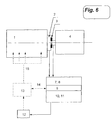
- FIG. 6 shows a preferred device in which the method for controlling single cylinder injection quantities is used.
- the torque signal is calculated in a self-calibrating manner from two angular velocity signals - on both sides of the elastic intermediate element between the flywheel and the load device.
- Figure 1 shows the delimitation of the system under consideration. Accordingly, the internal combustion engine is separated immediately after the flywheel from the rest of the drive train - in the case of the example: from the test bench brake.
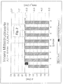
- Figure 2 shows values for indexed mean pressures of an 8 cylinder truck engine.
- the cylinder pressure curve of cylinder 1 was multiplied by 0.95, so that the pi value for cylinder 1 - compared to the pi values of cylinders 2 to 8, which are all the same - was also reduced by 5%.
- delta_pi the common mean in bar form
- E_S does not correctly represent the course of the stored energy: torsional vibrations in the crankshaft falsify the amplitude in the ignition frequency and torsional vibrations in the clutch - stimulated by the non-uniform load torque - even cause an energy increase in the expansion range of cylinder 1, which in this example is 5% weaker than the others.
- Such a 2-mass distribution can be understood as an approximation for the real torsional vibration system, which has significantly more partial masses and degrees of freedom.
- FIG. 5 shows that, especially for evaluating deviations in the individual cylinder power - for example for equalizing injection quantities - the combined evaluation of angular velocity and torque achieves decisive advantages in accuracy, so that an application in control systems is possible in the first place.
- the accuracy of the results can be increased even further by correcting cylinder-specific errors that primarily depend on the operating state (e.g. remaining errors as a result of high-frequency torsional vibrations) via an engine-specific correction map.
- E total ( ⁇ OTj) I. ⁇ s ⁇ ⁇ ⁇ s j 2nd 2nd
- I. S ⁇ Mean of I S according to Eq. 7 - - maximum in the interval of ⁇ OTj - Firing interval 2nd to ⁇ OTj + Firing interval 2nd
- ⁇ sj ⁇ Mean of ⁇ s ( ⁇ ) - maximum in the interval of ⁇ OTj - Firing interval 2nd to ⁇ OTj + Firing interval 2nd
- the size is absolutely comparable with deviations in the indicated medium pressure [bar] and is furthermore not restricted to any special operating conditions of the internal combustion engine.
- a fluctuating load torque is e.g. also given in ship engines, and not only in the auxiliary units, for example for driving compressors or pumps, but also in the main drive motors.
- Load, swell and water depth are factors that influence the propeller characteristics, so that the propeller load is not a clear function of the speed, both on the high seas and in coastal and inland waters.
- the method presented here can therefore also be used to advantage in this area, for example in a device with which the individual cylinder output is continuously monitored and / or set within certain limits.
- the spring characteristic is basically known about the angle of rotation of the elastic element, but can change slowly over the course of years of use or with the temperature.
- the spring constant is continuously determined using the following method:
- the current recalibration of the spring constant is based on Hook's law when measuring the differential angle using a linear-elastic element :
- Eq. 21 iteratively determines the current c-value and then again ⁇ 0 , and these values are preferably linked to the respective past values by weighted averaging and are thus kept up to date with regard to slow changes in the spring constants.
- This adaptation is interrupted immediately when the condition of the periodicity of ⁇ B, S over the engine cycle is no longer fulfilled - that is, when slip occurs, which typically occurs when the vehicle is disengaged. Then the previous values of ⁇ 0 become invalid, but the current value for the spring constant c represents the initial value for the next engaged state.
- the monitoring of a possible clutch slip can advantageously also be used in vehicle applications for the early detection of clutch wear, namely, if slippage is found under continuously high load.
- spring constants are preferably dependent on the amount of torque in the coupling saved.
- the following is suggested as a procedure for the recalibration: the values for ⁇ ⁇ B, S ⁇ and are recorded over a large number of work cycles (e.g. 200) after each engagement process, with a corresponding number of value pairs (in each case approx. 25% of the total number) being present at least for low and high loads.
- a polynomial which corresponds to the basic characteristic of the coupling is fitted into this set of points, for example using the "least squares method":
- a quadratic polynomial can be used:
- the calculated spring constants are subsequently saved as weighted average values with the past values. -
- the validity of the polynomial coefficient is always limited to an engaged state.
- the values of the spring constants as a function of the current engine load remain valid until an updated calibration is completed in the background has been. A continuous determination of the single cylinder torque is thus possible even in the case of the nonlinear, elastic intermediate element. This procedure can of course also be used in the case of linear-elastic elements.
- a device that measures the angular velocity and the torque.
- FIG. 6 shows a preferred embodiment, which is used here, for example, in a control circuit for equalizing single-cylinder injection quantities:
- An internal combustion engine 1 drives a load device 4 via a flywheel 2 and an elastic intermediate element 3.
- the angle gradients (approx. 30 to 200 marks) and a reference mark (trigger or an irregular mark spacing) are measured in time on both the flywheel side 5 and the load side 6 of the elastic intermediate element.
- the output values for calculating the single cylinder torque values are provided in an angular velocity calculation unit 7 and in a torque calculation unit 8.
- the spring constant is continuously updated in the self-calibration device 9 and the slip is monitored. Via a data interface 14 to the engine control electronics 13, both "unusual slip" can be reported and "the current average torque value" can be obtained.
- a diagnostic parameter is calculated in a single-cylinder torque calculation unit 10, which is preferably also corrected for cylinder-specific errors with a correction map 11, so that a single-cylinder torque measure 12 is obtained for each cylinder.
- This dimension is so precise that it can be used, for example, with the help of the engine control electronics 13 to regulate the signals for fuel quantity control for each cylinder 15.
Abstract
Description
Die Erfindung betrifft ein Diagnoseverfahren für mehrzylindrige Brennkraftmaschinen, wobei an zumindest einem kurbelgetriebenen Bauteil der Brennkraftmaschine für definierte Kurbelwinkelstellungen Winkelgeschwindigkeiten aufgenommen und daraus unter Berücksichtigung des jeweils wirksamen Gesamtträgheitsmomentes die jeweiligen Gesamtenergien bzw. dadurch repräsentierte Diagnosekenngrößen, wie insbesonders Einzelzylinder-Leistungsgrößen bzw. Einzelzylinder-Lastgrößen, bestimmt werden. Weiters betrifft die Erfindung auch ein Verfahren zur Erst-Einstellung bzw. zur bedarfsweisen Nach-Einstellung einer mittels eines derartigen Diagnoseverfahrens geprüften Brennkraftmaschine. Die Erfindung betrifft schließlich auch noch eine Einrichtung zur Diagnose mehrzylindriger Brennkraftmaschinen, mit zumindest einer Meßeinheit zur Bestimmung von Winkelgeschwindigkeiten an einem kurbelgetriebenen Bauteil der Brennkraftmaschine und einer damit in Verbindung stehenden Auswerteeinheit, in der unter Berücksichtigung von kurbelwinkelabhängigen Gesamtträgheitsmomenten Diagnosekenngrößen, wie insbesonders Einzelzylinder-Leistungsgrößen bzw. Einzelzylinder-Lastgrößen, ermittelt werden.The invention relates to a diagnostic method for multi-cylinder internal combustion engines, wherein angular velocities are recorded for at least one crank-driven component of the internal combustion engine for defined crank angle positions, and from this, taking into account the respectively effective total moment of inertia, the respective total energies or diagnostic parameters represented thereby, such as in particular single-cylinder power quantities or single-cylinder load variables, be determined. Furthermore, the invention also relates to a method for the initial adjustment or for the adjustment if necessary of an internal combustion engine checked by means of such a diagnostic method. Finally, the invention also relates to a device for diagnosing multi-cylinder internal combustion engines, with at least one measuring unit for determining angular velocities on a crank-driven component of the internal combustion engine and an associated evaluation unit, in which, taking into account crank angle-dependent total moments of inertia, diagnostic parameters, such as, in particular, single-cylinder power parameters or Single cylinder load sizes can be determined.
Verfahren bzw. Einrichtungen der genannten Art sind in verschiedenen Zusammenhängen, beispielsweise zur Erkennung von Zündaussetzern oder zur Gleichlaufregelung im Leerlauf, bekannt. Sie beruhen in vielen Fällen auf der Auswertung des Verlaufes der Kurbelwellen-Winkelgeschwindigkeit. So wird z.B. gemäß DE-A1 4 028 131 vorgeschlagen, die Zeitdauer für die Winkel spanne eines halben Zündabstandes vor dem oberen Totpunkt, also während die Kompressionsphase dominiert, mit der Zeitspanne zu vergleichen, die die Kurbelwelle benötigt um die gleiche Winkel spanne unmittelbar nach dem oberen Totpunkt zurückzulegen. Ab einer gewissen Abweichung dieser Zeitspannen wird auf einen Zündaussetzer am jeweiligen Zylinder entschieden. Weiters wurde gemäß EP-A 0 469 658 zur Beurteilung von Einzelzylinder-Leistungen generell eine Dreiteilung des Zündabstandes vorgesehen, um mit entsprechend wenigen Kurbelwinkelmarken die minimale und die maximale Winkelgeschwindigkeit anzunähern. Letztendlich wird dann die Einzelzylinder-Leistung am Anstieg der jeweiligen Winkelgeschwindigkeit in der Expansionsphase beurteilt.Methods and devices of the type mentioned are known in various contexts, for example for the detection of misfires or for synchronous control during idling. In many cases, they are based on the evaluation of the course of the crankshaft angular velocity. For example, According to DE-A1 4 028 131 proposed to compare the time period for the angular span of half an ignition interval before top dead center, that is to say while the compression phase dominates, with the time span which the crankshaft requires to cover the same angular span immediately after top dead center . From a certain deviation of these time periods, a misfire is decided on the respective cylinder. Furthermore, in accordance with EP-
Beide der genannten Methoden haben den unmittelbaren Nachteil, daß gleiche Abweichungen in den Einzelzylinder-Leistungen bei unterschiedlichen Drehzahlen zu unterschiedlich starken Abweichungen in den Winkelgeschwindigkeitsmaßen führen. Aus diesem Grunde ist man auch bei der Zündaussetzererkennung verschiedentlich dazu übergegangen, Differenzen in quadrierten, zylinderspezifischen Winkelgeschwindigkeitswerten als Rauhigkeitsmaßzahl heranzuziehen. So wird beispielsweise im SAE-Paper 930399 von M. Klenk et al gezeigt, daß damit bei Brennkraftmaschinen bis zu sechs Zylindern eine Zündaussetzererkennung im gesamten Kennfeld sichergestellt werden kann. Um dem Einfluß von Drehschwingungen der Kurbelwelle zu begegnen wird das Rauhigkeitsmaß einem kennfeldabhängigen Grenzwert gegenübergestellt, der allerdings zuvor experimentiell bestimmt werden muß. Trotzdem müssen schnelle Drehzahl- bzw. Lastwechselsituationen sowie beispielsweise Fahrten eines mit der geprüften Brennkraftmaschine ausgerüsteten Fahrzeuges auf unebener Straße von der Zündaussetzerüberwachung ausgenommen werden, da in diesen Fällen Antriebsstrangschwingungen angeregt werden, die nicht mehr durch einfache kennfeldabhängige Grenzwerte korrigiert werden können.Both of the methods mentioned have the direct disadvantage that the same deviations in the individual cylinder outputs at different speeds lead to deviations in the magnitude of the angular velocity that are different. For this reason, misfiring detection has also started to use differences in squared, cylinder-specific angular velocity values as a roughness measure. For example, in SAE paper 930399 by M. Klenk et al demonstrated that misfire detection can be ensured in the entire map in internal combustion engines with up to six cylinders. In order to counteract the influence of torsional vibrations of the crankshaft, the roughness measure is compared to a map-dependent limit value, which however must first be determined experimentally. Nevertheless, rapid speed or load change situations and, for example, journeys of a vehicle equipped with the tested internal combustion engine on uneven roads must be excluded from misfiring monitoring, since in these cases drive train vibrations are stimulated that can no longer be corrected by simple map-dependent limit values.
Weiters ist beispielsweise gemäß EP-A-0 434 665 bekannt, auf der Basis von einem oder mehreren Winkelgeschwindigkeitsverläufen (an mehreren Orten des Wellenstranges) ein Einzelzylinder-Leistungsmaß nach der sogenannten Energiepegelmethode aus dem Verlauf der gespeicherten kinetischen Energie zu ermitteln. Dabei werden einerseits der Massenkrafteinfluß und auch der Torsionsschwingungseinfluß grundsätzlich berücksichtigt und andererseits wird als Maßgröße ein sogenannter gemischter effektiver Mitteldruck berechnet, der es erlaubt, auch kleine Veränderungen von Einzelzylinderleistungswerten zu erkennen und nicht nur beispielsweise den Totalausfall eines Zylinders. In gewisser Weise nachteilig ist dabei allerdings der Umstand, daß nur jene Torsionsschwingungen kompensiert werden können, die innerhalb der gedachten Systemgrenzen ablaufen. D.h., sollte man Schwingungen im Antriebsstrang am Abtrieb der Brennkraftmaschine mitkorrigieren, so müßte der gesamte Antriebsstrang in das betrachtete System miteingeschlossen werden. Damit müßten allerdings auch entsprechend viele zusätzliche Winkelgeschwindigkeitsmessungen durchgeführt werden, was - neben der gewünschten Berücksichtigung der Torsionsschwingungen - auch zu einer Addition von Meßfehlern und damit nur bedingt zu Genauigkeitssteigerungen führen würde.Furthermore, according to EP-A-0 434 665, for example, it is known to determine a single cylinder power measure based on one or more angular velocity profiles (at several locations on the shaft train) using the so-called energy level method from the profile of the stored kinetic energy. On the one hand, the influence of the mass force and the influence of torsional vibrations are taken into account and, on the other hand, a so-called mixed effective mean pressure is calculated as a measurement, which allows small changes in individual cylinder power values to be recognized and not just the total failure of a cylinder, for example. To a certain extent, however, the disadvantage is that only those torsional vibrations can be compensated for that run within the intended system limits. This means that if you correct vibrations in the drive train at the output of the internal combustion engine, the entire drive train would have to be included in the system under consideration. However, this would also have to result in a correspondingly large number of additional angular velocity measurements, which - in addition to the desired consideration of the torsional vibrations - would also lead to an addition of measurement errors and thus only to a limited extent to accuracy increases.
Aufgabe der vorliegenden Erfindung ist es, Verfahren bzw. Einrichtungen der eingangs genannten Art so zu verbessern, daß die erwähnten Nachteile der bekannten Verfahren bzw. Einrichtungen vermieden werden und daß insbesonders beispielsweise die Genauigkeit der ermittelten Diagnosekenngrößen für die Einzelzylinderbewertung so gesteigert werden kann, daß nicht nur eine Zündaussetzererkennung, sondern etwa auch eine unmittelbare Regelung der den einzelnen Zylindern zugeführte Kraftstoffmenge ermöglicht wird. Diese Aufgabe soll weiters nicht nur im Leerlauf sondern bei allen Motordrehzahleninsbesonders auch im Vollastbereich - gelöst werden, was speziell etwa bei Diesel-Brennkraftmaschinen sehr vorteilhaft ist, die ja bei Vollast mit minimalem Luftüberschuß betrieben werden. Wenn dieser minimale Luftüberschußwert in einzelnen Zylindern unterschritten wird, steigt der unerwünschte Schadstoffausstoß überproportional.The object of the present invention is to improve methods and devices of the type mentioned at the outset in such a way that the disadvantages mentioned of the known methods and devices are avoided and in particular, for example, that the accuracy of the diagnostic parameters determined for the single-cylinder evaluation can be increased in such a way that not only misfire detection, but also a direct control of the amount of fuel supplied to the individual cylinders is made possible. This task is also to be solved not only at idling but also at all engine speeds, particularly in the full-load range, which is particularly advantageous, for example, in diesel internal combustion engines, which with full load minimal excess air can be operated. If this minimum air excess value in individual cylinders is undershot, the undesirable emission of pollutants increases disproportionately.
Die genannte Aufgabe wird gemäß der vorliegenden Erfindung bei einem Diagnoseverfahren der eingangs genannten Art dadurch gelöst, daß zusätzlich zu der bzw. den Winkelgeschwindigkeitsmessung(en) zumindest eine drehwinkel- bzw. zeitaufgelöste Drehmomentmessung an einer abtriebseitigen Systemgrenze vorgenommen und der dadurch repräsentierte jeweilige Energietransport über diese Systemgrenze bei der Bestimmung der Diagnosekenngrößen berücksichtigt wird. Die erfindungsgemäße Einrichtung zur Diagnose mehrzylindriger Brennkraftmaschinen zeichnet sich demgemäß dadurch aus, daß zumindest eine weitere Meßeinheit zur drehwinkel- bzw. zeitaufgelösten Drehmomentmessung an einer abtriebseitigen Systemgrenze vorgesehen und ebenfalls mit der Auswerteeinheit verbunden ist.According to the present invention, the stated object is achieved in a diagnostic method of the type mentioned at the outset in that, in addition to the angular velocity measurement (s), at least one rotational angle or time-resolved torque measurement is carried out on an output-side system boundary and the respective energy transport represented thereby System limit is taken into account when determining the diagnostic parameters. The device according to the invention for diagnosing multi-cylinder internal combustion engines is accordingly characterized in that at least one further measuring unit for measuring the angle of rotation or time-resolved torque is provided on a system boundary on the output side and is likewise connected to the evaluation unit.
Beim eingangs erwähnten Verfahren zur Erst-Einstellung einer mittels eines beschriebenen Diagnoseverfahrens geprüften Brennkraftmaschine ist gemäß der Erfindung entsprechend vorgesehen, daß mit Hilfe der auf einem Produktionsprüfstand ermittelten korrigierten Diagnosekenngrößen eine Grundeinstellung von geprüften Serien-Brennkraftmaschinen vorgenommen wird. Zur bedarfsweisen Nach-Einstellung einer mittels eines erfindungsgemäßen Diagnoseverfahrens geprüften Brennkraftmaschine wird mit Hilfe der auf einer Belastungseinrichtung bzw. on-board ermittelten korrigierten Einzelzylinder-Diagnosekenngrößen eine Einstellung von Einzelzylinder-Einspritzmengen auf einen Zielwert vorgenommen.In the method mentioned at the outset for the initial setting of an internal combustion engine tested by means of a described diagnostic method, provision is accordingly made in accordance with the invention for a basic setting of tested series internal combustion engines to be carried out with the aid of the corrected diagnostic parameters determined on a production test bench. In order to readjust an internal combustion engine tested by means of a diagnostic method according to the invention, the corrected individual cylinder diagnostic parameters determined on a loading device or on-board are used to set individual cylinder injection quantities to a target value.
Während aus der (bzw. den) Winkelgeschwindigkeitsmessung(en) Differenzen ermittelt werden können, die der Änderung der gespeicherten Energie innerhalb des betrachteten Systems infolge der Gaswirkungen einzelner Zylinder entsprechen, wird durch die zusätzlich Drehmomentmessung - vorzugsweise nach dem Schwungrad der Brennkraftmaschine - der zugehörige augenblickliche Energietransport über diese Systemgrenze erfaßt und in Rechnung gestellt. Damit wird man in vorteilhafter Weise unmittelbar von der Annahme unabhängig, daß das Drehmoment am Schwungrad im Zündabstand periodisch ist. Dies ist nämlich genau dann nicht der Fall, wenn z.B. im Antriebsstrang Torsionsschwingungen auftreten, oder aber Rückwirkungen von einer unebenen Fahrbahn oder dgl. der Brennkraftmaschine ein stark schwankendes Drehmoment abverlangen.While differences can be determined from the (or) angular velocity measurement (s) that correspond to the change in stored energy within the system under consideration due to the gas effects of individual cylinders, the additional instantaneous measurement - preferably according to the flywheel of the internal combustion engine - makes the associated instantaneous Energy transport recorded over this system boundary and billed. This advantageously makes one directly independent of the assumption that the torque on the flywheel is periodic in the ignition interval. This is not the case if, e.g. Torsional vibrations occur in the drive train, or feedback effects from an uneven roadway or the like require a strongly fluctuating torque from the internal combustion engine.
Die Erfindung stellt also eine wesentliche Verbesserung bzw. Verallgemeinerung der oben angesprochenen "Energiepegelmethode" dar. Diese vielseitig - und nicht nur etwa zur Einzelzylinder-Leistungsmessung - verwendbare, auf der Berechnung der im jeweiligen System aktuell gespeicherten Energie beruhende Methode wird verbessert, indem nicht nur der Energiepegelverlauf nach dem Stand der Technik sondern zusätzlich ein Drehmomentverlauf an einer Systemgrenze ausgewertet werden. Damit können auf erwähnte Weise Schwankungen der Antriebsstrangtorsion und des von außen auf die Brennkraftmaschine rückwirkenden Lastmomentes berücksichtigt werden, sodaß der erhaltene korrigierte Energiepegelverlauf praktisch ausschließlich von den wirkenden Gaskräften und der Reibung bestimmt ist.The invention thus represents an essential improvement or generalization of the above-mentioned "energy level method". This is versatile - and not only usable for single-cylinder power measurement The calculation of the energy currently stored in the respective system is improved by evaluating not only the energy level curve according to the prior art but also a torque curve at a system limit. In this way, fluctuations in the drive train torsion and the load torque that reacts from the outside of the internal combustion engine can be taken into account, so that the corrected energy level curve obtained is determined practically exclusively by the acting gas forces and the friction.
Als Diagnosekenngrößen im angesprochenen Sinne sind hier nun eine Reihe diagnostischer Größen zu verstehen, wie sie z.B. in der Indiziertechnik aus der Gesamtheit der gemessenen Brennraumdruckverläufe aller Zylinder abgeleitet werden können bzw. mit diesen in ursächlichem Zusammenhang stehen. Der erwähnte korrigierte Energiepegelverlauf bzw. der entsprechende Verlauf des korrigierten Moments enthält diagnostische Informationen über die gesamte Brennkraftmaschine und gleichzeitig auch über die einzelnen Zylinder; unter anderem bezüglich Drehmoment bzw. -leistung, Reibmoment bzw. -leistung, Kompression und Ladungswechsel. Zu all diesen "Zylinderdruckeffekten" können unter Nutzung des angesprochenen erfindungsgemäß verbesserten Verfahrens bzw. der entsprechenden Einrichtung diagnostische Aussagen gemacht werden, was insbesonders für Produktionsprüfungsanwendungen durch die Betrachtung des korrigierten Verlaufes der gespeicherten Energie bzw. von dessen Ableitung von Bedeutung ist.A number of diagnostic variables, such as those e.g. can be derived in the indexing technique from the entirety of the measured combustion chamber pressure curves of all cylinders or are causally related to them. The corrected energy level curve mentioned or the corresponding curve of the corrected torque contains diagnostic information about the entire internal combustion engine and at the same time also about the individual cylinders; among other things with regard to torque or power, friction torque or power, compression and charge changes. Diagnostic statements can be made about all these "cylinder pressure effects" using the method or the corresponding device improved according to the invention, which is particularly important for production test applications by considering the corrected course of the stored energy or its derivation.
In bevorzugter Ausgestaltung des erfindungsgemäßen Diagnoseverfahrens ist vorgesehen, daß zur Drehmomentmessung der jeweilige Verdrehwinkel zwischen einem auf der Kurbelwelle der Brennkraftmaschine angeordneten Schwungrad und einer nachgeschalteten Belastungseinrichtung gemessen und zusammen mit der Federkonstanten eines zwischen Schwungrad und Belastungseinrichtung liegenden elastischen Antriebsstrangelementes ausgewertet wird. Die Kalibrierung der Federkonstanten kann dabei bevorzugt anhand des mittleren Verdrehwinkels und eines zusätzlichen Maßes für den Mittelwert der Motorlast erfolgen. Dies ergibt eine sehr einfache Ausgestaltung des Verfahrens, wobei eine vorteilhafte Weiterbildung der erfindungsgemäßen Einrichtung auch vorsehen kann, daß die weitere Meßeinheit zur Drehmomentmessung mit der Meßeinheit zur Winkelgeschwindigkeitsmessung zusammengefaßt ist.In a preferred embodiment of the diagnostic method according to the invention it is provided that for torque measurement the respective angle of rotation between a flywheel arranged on the crankshaft of the internal combustion engine and a downstream load device is measured and evaluated together with the spring constant of an elastic drive train element located between the flywheel and load device. The spring constants can preferably be calibrated using the mean angle of rotation and an additional measure for the mean value of the engine load. This results in a very simple embodiment of the method, and an advantageous further development of the device according to the invention can also provide that the further measuring unit for torque measurement is combined with the measuring unit for angular velocity measurement.
Die Verdrehwinkelmessung zur Drehmomentmessung kann nach einer anderen Weiterbildung des erfindungsgemäßen Diagnoseverfahrens auch über einen Schaltkupplungsbelag erfolgen, wobei bei dauerhaft auftretendem Schlupf bei hoher Last ein frühzeitiger Kupplungsverschleiß diagnostiziert werden kann. Auf diese Weise können also auch zusätzliche, über die erwähnten Zylinderdruckeffekte hinausgehende Diagnoseaussagen gewonnen werden.According to another development of the diagnostic method according to the invention, the angle of rotation measurement for torque measurement can also be carried out via a clutch lining, with early clutch wear being diagnosed in the event of permanent slippage under high load. In this way, additional diagnostic statements that go beyond the cylinder pressure effects mentioned can also be obtained.
In weiters bevorzugter Ausgestaltung der Erfindung werden Differenzverläufe zwischen den Verläufen der korrigierten Diagnosekenngrößen der jeweils geprüften und einer als gut befundenen Brennkraftmaschine ausgewertet, wobei zur Entscheidung ob ein Fehler vorliegt, statistische Hilfsmittel - wie z.B. Gutzustandsstreubänder - herangezogen werden können.In a further preferred embodiment of the invention, difference profiles between the profiles of the corrected diagnostic parameters of the respectively tested internal combustion engine and an internal combustion engine which has been found to be good are evaluated, statistical aids - such as e.g. Good condition scatter bands - can be used.
Zum Ausgleich von höherfrequenten Torsionsschwingungen innerhalb des Kurbeltriebes kann in bevorzugter weiterer Ausgestaltung der Erfindung auch vorgesehen sein, daß die aufgenommene Schwungradwinkelgeschwindigkeit tiefpaßgefiltert wird.To compensate for higher-frequency torsional vibrations within the crank mechanism, it can also be provided in a preferred further embodiment of the invention that the recorded flywheel angular velocity is low-pass filtered.
Als weitere Ausgestaltungsform kann auch nach der Berechnung eines zunächst durch hochfrequente Kurbelwellendrehschwingungen verfälschten Einzelzylinderdrehmomentmaßes, das alleine aus der Schwungradwinkelgeschwindigkeit und der Drehmomentenmessung berechnet wurde, eine Korrektur der Ergebnisgröße mit einem Korrekturkennfeld erfolgen. Dieses Korrekturkennfeld muß nur einmalig pro Motortype-Kupplungskombination erstellt werden. Bei alleiniger Auswertung der Schwungradwinkelgeschwindigkeit - ohne die kombinierte Auswertung von Winkelgeschwindigkeit und Drehmoment - existiert ein derartiges Korrekturkennfeld aber nicht: Unterschiedliche Einzelzylinderdrehmomentbeiträge beeinflussen nämlich den Anregungszustand im niedrigen Frequenzbereich, in dem die Kupplungstorsionsschwingungen ablaufen. Damit hängt die Heftigkeit der Kupplungstorsionsschwingungen und damit ihr verfälschender Einfluß auf die Ergebnisgröße davon ab, ob die Zylinder gleichmäßig arbeiten - oder nicht. Das heißt, daß auch das Korrekturkennfeld davon abhängen muß, sodaß es nicht einmalig bestimmt werden kann.As a further embodiment, the result variable can also be corrected using a correction map after the calculation of a single-cylinder torque measure which was initially falsified by high-frequency crankshaft torsional vibrations and which was calculated solely from the flywheel angular velocity and the torque measurement. This correction map only has to be created once for each engine type-clutch combination. However, when evaluating the flywheel angular velocity alone - without the combined evaluation of angular velocity and torque - such a correction map does not exist: Different individual cylinder torque contributions influence the excitation state in the low frequency range in which the clutch torsional vibrations occur. The severity of the coupling torsional vibrations and thus their falsifying influence on the result size depends on whether the cylinders work evenly - or not. This means that the correction map must also depend on it so that it cannot be determined once.
In weiterer Ausgestaltung des erfindungsgemäßen Diagnoseverfahrens können aus den Verläufen von korrigierten Einzelzylinder-Diagnosekenngrößen Zündaussetzer einzelner Zylinder bestimmt werden.In a further embodiment of the diagnostic method according to the invention, misfires of individual cylinders can be determined from the courses of corrected single-cylinder diagnostic parameters.
Besonders vorteilhaft ist eine Weiterbildung des erfindungsgemäßen Diagnoseverfahrens, gemäß welcher die Brennkraftmaschine bei diesem Verfahren zündungslos geschleppt wird, da damit einfach und schnell diagnostiziert werden kann (Kaltprüfung).A further development of the diagnostic method according to the invention, according to which the internal combustion engine is towed without ignition in this method, is particularly advantageous, since it can be used to diagnose it simply and quickly (cold test).
Für die Auswertung bzw. Erhöhung der Aussagekraft des erfindungsgemäßen Diagnoseverfahrens von Vorteil ist eine weitere Ausgestaltung, gemäß welcher mindestens ein Winkelgeschwindigkeitsverlauf im Bereich eines modalen Schwingungsknotens der Kurbelwelle aufgenommen wird.A further embodiment is advantageous for evaluating or increasing the significance of the diagnostic method according to the invention, according to which at least one angular velocity curve is recorded in the region of a modal vibration node of the crankshaft.
In bevorzugter weiterer Ausgestaltung der Erfindung ist vorgesehen, daß zur Steuerung bzw. Regelung einer in Betrieb befindlichen Brennkraftmaschine eine adaptive Einstellung von Parametern und/oder Zielwerten der Steuerung bzw. Regelung mit Hilfe der on-board ermittelten korrigierten Einzelzylinder-Diagnosekenngrößen vorgenommen wird.In a preferred further embodiment of the invention it is provided that to control or regulate an internal combustion engine in operation, an adaptive setting of parameters and / or target values of the control or regulation is carried out with the aid of the corrected single-cylinder diagnostic parameters determined on-board.
Eine weitere Ausgestaltung der erfindungsgemäßen Einrichtung ist schließlich entsprechend gekennzeichnet durch eine Verbindung mit einem Motormanagementsystem zur adaptiven Einstellung von Parametern und/oder Zielwerten für die Steuerung bzw. Regelung der Brennkraftmaschine.A further embodiment of the device according to the invention is finally characterized accordingly by a connection to an engine management system for adaptively setting parameters and / or target values for the control or regulation of the internal combustion engine.
Unter der Voraussetzung der Gleichmäßigkeit von Reibmoment, Kompression und Ladungswechsel kann gemäß der Erfindung also sehr einfach ein Einzelzylinder-Drehmoment ermittelt werden, was beispielsweise für die erwähnten on-board-Anwendungen zur "Zylindergleichstellung" sehr wichtig ist. Dieses Einzelzylinderdrehmoment erlaubt weiters insbesonders diagnostische Schlüsse auf die allgemeine Funktion des Einspritzsystems einer Brennkraftmaschine, die eingespritzte Kraftstoffmenge selbst, sowie eventuelle Zündaussetzer.Provided that the friction torque, compression and charge exchange are uniform, a single cylinder torque can thus be determined very easily in accordance with the invention, which is very important, for example, for the on-board applications mentioned for "cylinder equalization". This single-cylinder torque also allows, in particular, diagnostic conclusions to be drawn about the general function of the injection system of an internal combustion engine, the amount of fuel injected itself, and possible misfires.
Bevorzugte Einsatzgebiete für die beschriebenen erfindungsgemäßen Verfahrensausgestaltungen bzw. die entsprechenden Einrichtungen sind Produktionsprüfstände mit geschleppter Brennkraftmaschine (Kalttest), Produktionsprüfstände mit gefeuerter Brennkraftmaschine sowie on-board-Anwendungen. Im Werkstattbereich wird dagegen im allgemeinen im Leerlauf der Brennkraftmaschine getestet, sodaß dort die einfache, unkorrigierte Energiepegelmethode nach dem Stande der Technik zumeist ausreichend sein wird.Preferred areas of application for the described method configurations according to the invention or the corresponding devices are production test benches with a towed internal combustion engine (cold test), production test benches with a fired internal combustion engine and on-board applications. In the workshop area, on the other hand, testing is generally carried out while the internal combustion engine is idling, so that the simple, uncorrected energy level method according to the prior art will usually be sufficient there.
Es kann damit beispielsweise die erwähnte Erst-Einstellung einer Brennkraftmaschine am Produktionsprüfstand erfolgen; andererseits kann - zweckmäßigerweise unter Nutzung von on-board-Einrichtungen für die Ermittlung von E(α) und/oder M(α) - eine Nacheinstellung der Brennkraftmaschine (fallweise, periodisch, laufend), eine Regelung (eventuell adaptiv) oder eine Diagnose durchgeführt werden. Zur Auswertung der "korrigierten Energiepegelverläufe" können entweder absolute Kenngrößen ermittelt oder aber relative Kenngrößen von einerseits zu testender Brennkraftmaschine und andererseits bekannter Brennkraftmaschine im Gutzustand erfolgen. Weiters können Differenzverläufe und/oder Differenzkenngrößen von unbekannt und bekannt (gut) berechnet oder statistische Methoden und Maße wie etwa Streubänder, Zuverlässigkeitsbereiche, etc. genutzt werden.For example, the aforementioned initial setting of an internal combustion engine can take place on the production test bench; on the other hand - expediently using on-board devices for determining E (α) and / or M (α) - the internal combustion engine can be readjusted (occasionally, periodically, continuously), regulation (possibly adaptive) or diagnosis become. To evaluate the "corrected energy level curves", either absolute parameters can be determined or relative parameters of the internal combustion engine to be tested on the one hand and the known internal combustion engine on the other hand can be in good condition. Furthermore, differential courses and / or differential parameters of unknown and known (good) can be calculated or statistical methods and dimensions such as scatter bands, reliability ranges, etc. can be used.
Das zur erwähnten Korrektur dienende, zusätzlich ermittelte Drehmoment kann mit üblichen, bekannten Drehmomentsensoren bestimmt oder - auf jedenfalls an sich bekannte Art - aus dem Verdrehwinkel eines drehelastischen Teiles des Antriebstranges ermittelt werden. Vorteilhaft kann dabei wie erwähnt fallweise, periodisch oder laufend eine Kalibrierung der Federkonstanten aus einer bekannten mittleren Motorlast erfolgen, womit mit vorhandenen meßtechnisch geringwertigen Bauteilen der erforderliche dynamische Anteil am Motordrehmoment ermittelbar ist, ohne hochpräzise, teure und platzraubende Drehmomentmeßwellen oder dgl. einsetzen zu müssen. Zu beachten ist, daß eine derartige lineare Kalibrierung im wesentlichen nur im Bereich des betreffenden Arbeitspunktes (Lastpunktes) gilt wenn die Federlinie selbst nicht linear ist.The additionally determined torque serving for the mentioned correction can be determined with conventional, known torque sensors or - in any case known per se - can be determined from the angle of rotation of a torsionally elastic part of the drive train. How can be advantageous mentioned occasionally, periodically or continuously, the spring constants are calibrated from a known average engine load, so that the required dynamic portion of the engine torque can be determined with existing low-quality components, without having to use high-precision, expensive and space-consuming torque measuring shafts or the like. It should be noted that such a linear calibration essentially only applies in the area of the relevant working point (load point) if the spring line itself is not linear.
Falls zur zusätzlichen Drehmomentmessung auf erwähnte Weise die Elastizität der Kupplung der Brennkraftmaschine verwendet wird, muß auch der Schlupf überwacht bzw. ausgeschlossen werden und insbesonders auch die Wellenverdrehung beim Auskuppeln berücksichtigt werden. Verbleibt dagegen nach dem Einkuppeln ein Restschlupf, so kann aus diesem auf Kupplungsverschleiß geschlossen werden.If the elasticity of the clutch of the internal combustion engine is used for the additional torque measurement in the manner mentioned, the slip must also be monitored or excluded and in particular the shaft rotation when disengaging must also be taken into account. If, on the other hand, there is residual slip after engaging, this indicates that the clutch is worn.
In weiterer Folge wird die Erfindung an Hand eines Beispiels von einem LKW-Motor erläutert:The invention is explained below using an example of a truck engine:
Fig. 1 zeigt die Abgrenzung des betrachteten Systems.1 shows the delimitation of the system under consideration.
Fig. 2 zeigt die inneren Mitteldruckwerte von 8 Zylinderdruckverläufen, die als Eingabe in eine Drehschwingungssimulationsrechnung dienen.2 shows the inner mean pressure values of 8 cylinder pressure curves, which serve as input in a torsional vibration simulation calculation.
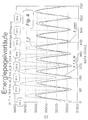
Fig. 3 zeigt als Ergebnis der Drehschwingungssimulation in der Form der Winkelgeschwindigkeitsverläufe an den Orten, an denen die Winkelgeschwindigkeit meßbar ist. Zusätzlich ist der Verlauf des Schnittmomentes zwischen Schwungrad und Bremse aufgetragen.3 shows the result of the torsional vibration simulation in the form of the angular velocity profiles at the locations where the angular velocity can be measured. The curve of the cutting torque between the flywheel and the brake is also plotted.
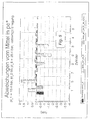
Fig. 4 zeigt Energiepegelverläufe, und zwar in einem Fall auf der Basis des Schwungradwinkelgeschwindigkeitsverlaufes und im anderen Fall erfindungsgemäß korrigiert.4 shows energy level profiles, specifically in one case on the basis of the flywheel angular velocity profile and in the other case corrected according to the invention.
Fig. 5 zeigt das jeweilige Ergebnis der Einzelzylinderdrehmomentenbewertung im Vergleich mit der absoluten Abweichung der pi-Werte von ihrem Mittelwert über alle Zylinder.5 shows the respective result of the single-cylinder torque evaluation in comparison with the absolute deviation of the pi values from their mean value over all cylinders.
Fig. 6 zeigt eine vorzugsweise Einrichtung in der das Verfahren zur Regelung von Einzelzylindereinspritzmengen genutzt wird. Dabei wird das Drehmomentensignal aus zwei Winkelgeschwindigkeitssignalen - beiderseits des elastischen Zwischenelements zwischen Schwungrad und Belastungseinrichtung- in selbstkalibrierender Art und Weise berechnet.FIG. 6 shows a preferred device in which the method for controlling single cylinder injection quantities is used. The torque signal is calculated in a self-calibrating manner from two angular velocity signals - on both sides of the elastic intermediate element between the flywheel and the load device.
Figur 1 zeigt die Abgrenzung des betrachteten Systems. Demnach wird die Brennkraftmaschine unmittelbar nach dem Schwungrad vom Rest des Antriebsstranges - im Fall des Beispieles: von der Prüfstandsbremse - abgetrennt.Figure 1 shows the delimitation of the system under consideration. Accordingly, the internal combustion engine is separated immediately after the flywheel from the rest of the drive train - in the case of the example: from the test bench brake.
Innerhalb des so definierten "offenen mechanischen Systems" gilt - für ein beliebiges Winkelintervall: Δα=α2 - α1 - die folgende Energiebilanz:
Dabei bedeuten:Here mean:
Indices:
- i
- innere, von den Gaskräften aller Zylinder herrührend
- j
- Zylinderindex
- r
- in Folge von allen Reibungsanteilen innerhalb der Systemgrenze
- außen
- von der Belastungseinrichtung her wirkend (positiv, wenn Motor geschleppt wird)
- i
- internal, resulting from the gas forces of all cylinders
- j
- Cylinder index
- r
- as a result of all friction components within the system limit
- Outside
- acting from the load device (positive if engine is being towed)
Formelzeichen:
- W
- Arbeit
- M
- Moment
- E
- Energie

- W
- job
- M
- moment
- E
- energy
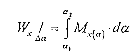
Andererseits kann der Verlauf der Arbeiten in Folge der Gaskräfte und der Motorreibung auch als Funktion des Kurbelwinkels dargestellt werden. Dazu wird α2 = α gesetzt und von einem beliebigen Startwert α0 aus variiert.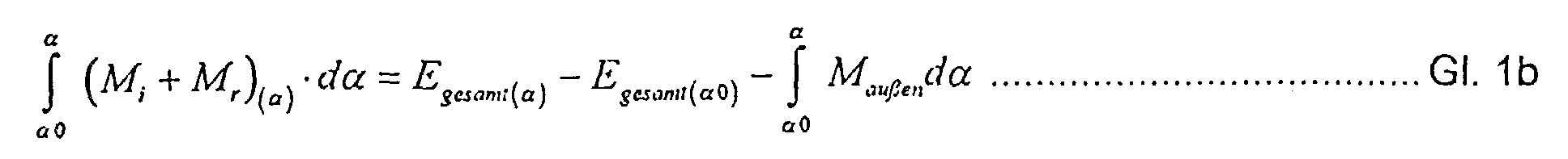
Dieser Verlauf steigt - bei gefeuertem Motor - mit dem Kurbelwinkel stark an. Aus den Differenzen in diesem Verlauf kann einerseits der Absolutwert für den "gemischten effektiven Mitteldruck" für jeden einzelnen Zylinder berechnet werden. (Vgl. Gl. 12)This curve increases - with the engine fired - with the crank angle. On the one hand, the differences in this course can be used to calculate the absolute value for the “mixed effective mean pressure” for each individual cylinder. (See Eq. 12)
Differenziert man Gleichung 1b nach α, so läßt sich andererseits der Verlauf der aufsummierten Gaskraftdrehmomente zuzüglich des Motorreibmomentes direkt errechnen:![]()
![]()
An Hand dieses Verlaufes lassen sich die Gaskraftwirkungen der einzelnen Zylinder besonders deutlich überwachen.The gas force effects of the individual cylinders can be monitored particularly clearly on the basis of this profile.
Vergleiche, ob solche Verläufe innerhalb eines Gutzustandsstreubandes liegen, sind insbesondere in der Produktionsprüfung von Motoren zweckmäßig. Auch hier verfälschen oft Antriebsstrangschwingungen das Diagnoseergebnis; wenn es entweder nur auf einer Winkelgeschwindigkeitsmessung oder nur auf einer Drehmomentmessung beruht. Dies gilt insbesondere für Kalttestverfahren, bei denen der Verbrennungsmotor bei niedriger Drehzahl geschleppt wird, die meist in der Nähe der Resonanzfrequenz der Einheit "Motor - Kupplung - Antriebseinrichtung" liegt.Comparisons of whether such courses lie within a good condition scatter band are particularly useful in the production testing of engines. Here, too, drive train vibrations often falsify the diagnostic result; if it is based either only on an angular velocity measurement or only on a torque measurement. This applies in particular to cold test methods in which the internal combustion engine is towed at a low speed, which is usually close to the resonance frequency of the "motor - clutch - drive device" unit.
Verwendet man
![]()

![]()
Er entspricht dem Verlauf der gespeicherten Energie beim Stationärbetrieb eines Motors, wenn das äußere Drehmoment konstant ist. Aus geeigneten Differenzbildungen in diesem Verlauf kann die Abweichung des "inneren Mitteldruckes" für jeden Zylinder vom mittleren pi-Wert aller Zylinder berechnet werden (vgl. Gl. 13).It corresponds to the course of the stored energy during stationary operation of an engine when the external torque is constant. The deviation of the "internal mean pressure" for each cylinder from the mean pi value of all cylinders can be calculated from suitable differences in this course (cf. Eq. 13).
Figur 2 zeigt Werte für indizierte Mitteldrücke, eines 8 Zylinder LKW-Motors. Der Zylinderdruckverlauf von Zylinder 1 wurde mit 0,95 multipliziert, so daß sich der pi-Wert für Zylinder 1 - im Vergleich zu den pi-Werten der Zylinder 2 bis 8, die alle gleich sind, ebenfalls um 5 % reduzierte.Figure 2 shows values for indexed mean pressures of an 8 cylinder truck engine. The cylinder pressure curve of
Weiters ist in Fig. 2 auch die Abweichung dieser pi-Werte vom gemeinsamen Mittelwert in Balkenform dargestellt (delta_pi). Zur Gleichstellung von Kraftstoffmengen müssen diese Abweichungen möglichst klein gehalten werden. Das heißt, daß die Meßgröße für diese Abweichung in hoher Genauigkeit vorliegen muß, so daß beispielsweise eine Minderleistung eines Zylinders um 5 % deutlich abgebildet sein muß.2 also shows the deviation of these pi values from the common mean in bar form (delta_pi). In order to equalize fuel quantities, these deviations must be kept as small as possible. This means that the measured variable for this deviation must be present with a high degree of accuracy, so that, for example, an underperformance of a cylinder by 5% must be clearly shown.
Weil diese Maßgröße aus einfach und dauerhaft meßbaren Signalen berechnet werden muß, sind in Figur 3 die Winkelgeschwindigkeitsverläufe, so wie sie am freien Motorende ("om_f"), am Schwungrad ("om_S") und auf der Belastungseinrichtung (om_B) zu erwarten sind, sowie das Drehmoment ("-Maußen"), das von der Kupplung übertragen wird, dargestellt.Because this measure must be calculated from signals that can be measured simply and permanently, the angular velocity curves in FIG. 3 are to be expected as they are to be expected at the free engine end ("om_f"), on the flywheel ("om_S") and on the loading device (om_B). and the torque ("-M outside ") that is transmitted from the clutch.
Diese Ergebnisse stammen aus einer Simulationsrechnung bei 1400 1/min, wobei auf der Belastungseinrichtung ("Prüfstandsbremse") ein sinusförmiges, störendes Drehmoment angreift. Dieses Erregermoment hat eine Amplitude von 200 Nm und die Periodendauer eines Motorzyklusses - es stellt eine denkbare Rückwirkung dar, wie sie von einem LKW-Antriebsstrang - beispielsweise bei einem Anfahrvorgang oder auf unebener Fahrbahn - ohne weiters ausgehen kann.These results come from a simulation calculation at 1400 1 / min, a sinusoidal, disturbing torque acting on the load device ("test bench brake"). This excitation torque has an amplitude of 200 Nm and the period of an engine cycle - it represents a conceivable reaction, as can easily be expected from a truck drive train - for example during a start-up process or on an uneven road surface.
Durch diese Rückwirkung kann - alleine aus den Winkelgeschwindigkeitsverläufen - kein brauchbares Maß für die Einzelzylinderleistung abgeleitet werden. Wird der Energiepegelverlauf aber erfindungsgemäß mit der Drehmomentmessung an der Systemgrenze korrigiert (Gl. 5), so kann die Wirkung der Gaskraftdrehmomente abzüglich der Reibungsmomente in voller Winkelauflösung dargestellt werden:Due to this reaction, a usable measure of the individual cylinder power cannot be derived from the angular velocity curves alone. However, if the energy level curve is corrected according to the invention with the torque measurement at the system boundary (Eq. 5), the effect of the gas force torques minus the frictional moments can be shown in full angular resolution:
Figur 4 zeigt zur Veranschaulichung zwei Energiepegelverläufe ("E_S" und "E_f_S_M"), die aus den Ergebnissen der Drehschwingungssimulationsrechnung abgeleitet sind, im Vergleich zum Energiepegelverlauf, der sich für ein starr angesetztes und nicht erregtes System ergibt (E_starr):
"E_S" wurde alleine auf der Basis der Schwungradwinkelgeschwindigkeit (ωs) berechnet:![]()
![]()
- wobei Irot0 =
- Summe aller Teilträgheitsmomente innerhalb der Systemgrenzen (rotierende Massen)
- Ios(α)
- Trägheitsanteil zur Berücksichtigung der oszillierenden Massen (siehe EP 0434 665A1,
Seite 5 / Zeile 34bis Seite 6 / Zeile 43).
"E_S" was calculated based solely on the flywheel angular velocity (ω s ):
- where I rot0 =
- Sum of all partial moments of inertia within the system limits (rotating masses)
- I os (α)
- Inertia component to take into account the oscillating masses (see EP 0434 665A1,
page 5 / line 34 topage 6 / line 43).
Zur Bewertung dieses Ergebnisses ist als Referenz der Verlauf E_starr eingetragen:![]()
Is(α) nach Gl. 7 und
- ωstarr
- Ergebnis einer Simulationsrechnung bei der die Kurbelwelle starr und das Drehmoment am Schwungrad konstant war.
I s (α) according to Eq. 7 and
- ω rigid
- Result of a simulation calculation in which the crankshaft was rigid and the torque on the flywheel was constant.
Wie Figur 4 zeigt, stellt E_S den Verlauf der gespeicherten Energie nicht korrekt dar: - Torsionsschwingungen in der Kurbelwelle verfälschen die Amplitude in der Zündfrequenz und Torsionsschwingungen in der Kupplung - angeregt durch das ungleichförmige Lastmoment - sorgen sogar für eine Energiezunahme im Expansionsbereich von Zylinder 1, der ja in diesem Beispiel um 5 % schwächer ist, als die anderen.As FIG. 4 shows, E_S does not correctly represent the course of the stored energy: torsional vibrations in the crankshaft falsify the amplitude in the ignition frequency and torsional vibrations in the clutch - stimulated by the non-uniform load torque - even cause an energy increase in the expansion range of
Dagegen zeigt der Verlauf "E_f_S_M" eine sehr gute Annäherung an den Verlauf von E_starr, der ja direkt von den Gaskräften abzüglich der Motorreibung geprägt ist: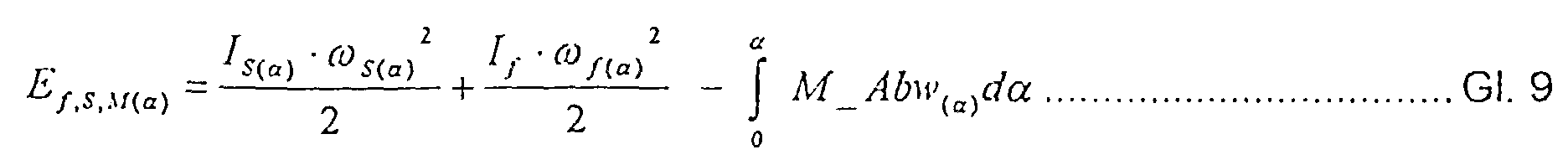
![]()
- wobei: Iso
- rotierender Anteil des schwungradseitigen Trägheitsmomentes
- Ios(α)
- Trägheitsmomentenanteil zur Berücksichtigung der oszillierenden Massen (siehe EP 0434665A1,
Seite 5 / Zeile 34bis Seite 6 / Zeile 43). - If
- rotierender Anteil des Motorträgheitsmomentes am freien Motorende,
- f
- freies Kurbelwellenende und
- S
- Schwungrad
z.b. Massenerhaltung:

Impulserhaltung:

- where: I so
- rotating part of the moment of inertia on the flywheel side
- I os (α)
- Moment of inertia to take account of the oscillating masses (see EP 0434665A1,
page 5 / line 34 topage 6 / line 43). - I f
- rotating part of the motor moment of inertia at the free motor end,
- f
- free crankshaft end and
- S
- flywheel
e.g. mass conservation:
Conservation of momentum:
So eine 2-Massenaufteilung kann als Näherung für das reale Drehschwingungssystem aufgefaßt werden, das wesentlich mehr Teilmassen und Freiheitsgrade aufweist.
Dabei bedeutet:
- pe*j
- "gemischter effektiver Mitteldruck" für den Zylinder "j"
- αOTj
- Kurbelwinkel im Zünd OT des Zylinders "j"
- αOTj+1
- Kurbelwinkel im Zünd OT des Zylinders "j+1"
- pe * j
- "mixed effective medium pressure" for cylinder "j"
- α OTj
- Crank angle in the ignition TDC of the cylinder "j"
- α OTj + 1
- Crank angle in the ignition TDC of the cylinder "j + 1"
Zur Bewertung von unterschiedlichen Einspritzmengen wird vorzugsweise die Abweichung vom Mittelwert aller pe* Werte: delta_pe*j berechnet: Weil sich pi und pe nur um pr unterscheiden, das ja dem Anteil eines Zylinders an der Motorgesamtreibung entspricht und definitionsgemäß für alle Zylinder gleich ist, gilt:![]()
- e
- effektiver
- i
- innerer
- r
- auf Grund der Motorreibung
- e
- more effective
- i
- inner
- r
- due to engine friction
beziehungsweise: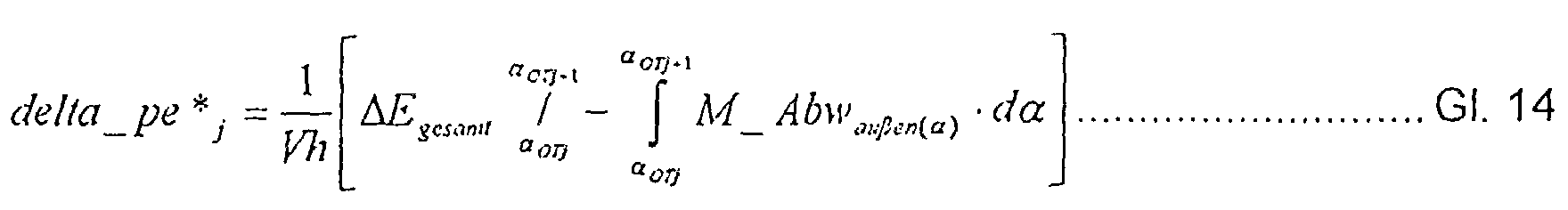
Weil die Kurbelwellentorsionsschwingungen hochfrequent sind, können hier weiters die Werte für Egesamt (αOTj) alleine auf der Basis einer tiefpaßgefilterten bzw. stark geglätteten Schwungradwinkelgeschwindigkeit mit guter Näherung berechnet werden: Wie Fig. 4 zeigt, kann bereits diese erste näherungsweise Berücksichtigung der Kurbelwellentorsionsschwingungen den Großteil der hochfrequenten Fehler in der Energiepegelverlaufsberechnung von "E_S" beseitigen. - Demgegenüber gleicht die Berücksichtigung des Drehmomentes an der Systemgrenze die niederfrequenten Drehschwingungen aus, die abtriebsseitig den Winkelgeschwindigkeitsverlauf des Schwungrades beeinflussen. Insgesamt kann also mit dem Verlauf (Ef,S,M) die Auswirkung der Gaskräfte - auch an einem stark schwingenden System, wie es in der Realität oft vorliegt - fast vollständig rekonstruiert werden; und zwar mit einfachen Rechenoperationen, die entweder in einem Auswertegerät, in einem Motormanagementsystem oder sogar direkt in einer Sensoreinheit ablaufen können.Because the crankshaft torsional vibrations are high-frequency, the values for E total (αOTj) can also be calculated with good approximation solely on the basis of a low-pass filtered or highly smoothed flywheel angular velocity: As FIG. 4 shows, this first approximate consideration of the crankshaft torsional vibrations can eliminate the majority of the high-frequency errors in the energy level curve calculation of "E_S". - In contrast, the consideration of the torque at the system boundary compensates for the low-frequency torsional vibrations, which influence the angular velocity curve of the flywheel on the output side. All in all, the course (E f, S, M ) of the effect of the gas forces - even on a strongly vibrating system, as is often the case in reality - can be almost completely reconstructed; with simple arithmetic operations that can either take place in an evaluation device, in an engine management system or even directly in a sensor unit.
Somit erkennt man an Fig. 4 die hohe Bedeutung der gemeinsamen Auswertung von Winkelgeschwindigkeit(en) und Drehmoment für alle jene Anwendungen, bei denen die Annahme eines konstanten - oder zumindest streng im Zündabstand periodischen - Drehmomentes an der Systemgrenze nicht erfüllt ist.4 shows the great importance of the joint evaluation of angular velocity (s) and torque for all those applications in which the assumption of a constant - or at least strictly periodic in the ignition interval - torque at the system limit is not fulfilled.
Darüber hinaus zeigt Fig. 5, daß man speziell zur Bewertung von Abweichungen in der Einzelzylinderleistung - beispielsweise zur Gleichstellung von Einspritzmengen - durch die kombinierte Auswertung von Winkelgeschwindigkeit und Drehmoment entscheidende Genauigkeitsvorteile erreicht, so daß eine Anwendung in Regelungssystemen überhaupt erst ermöglicht wird.In addition, FIG. 5 shows that, especially for evaluating deviations in the individual cylinder power - for example for equalizing injection quantities - the combined evaluation of angular velocity and torque achieves decisive advantages in accuracy, so that an application in control systems is possible in the first place.
Dabei kann die Genauigkeit der Ergebnisse noch dadurch gesteigert werden, daß zylinderspezifische Fehler, die in erster Linie vom Betriebszustand abhängen (z.B. verbleibende Fehler in Folge von hochfrequenten Torsionsschwingunggen),über ein motorspezifisches Korrekturkennfeld bereinigt werden.The accuracy of the results can be increased even further by correcting cylinder-specific errors that primarily depend on the operating state (e.g. remaining errors as a result of high-frequency torsional vibrations) via an engine-specific correction map.
Als Maß für die Einzelzylinderleistung wird der sogenannte ,,gemischte effektive Mitteldruck" (pe*j) für jeden Zylinder "j" berechnet (siehe z. B.auch EP 0434665A1, Seite 3, Zeile 48 bis Seite 7, Zeile 27).The so-called "mixed effective mean pressure" (pe * j ) for each cylinder "j" is calculated as a measure of the individual cylinder output (see also EP 0434665A1,
Für Motoren mit konstantem Zündabstand gilt:
Dabei bedeutet:
- pe*j
- "gemischter effektiver Mitteldruck" für den Zylinder "j"
- αOTj
- Kurbelwinkel im Zünd OT des Zylinders "j"
- αOTj+1
- Kurbelwinkel im Zünd OT des Zylinders "j+1"
- pe * j
- "mixed effective medium pressure" for cylinder "j"
- α OTj
- Crank angle in the ignition TDC of the cylinder "j"
- α OTj + 1
- Crank angle in the ignition TDC of the cylinder "j + 1"
Zur Bewertung von unterschiedlichen Einspritzmengen wird vorzugsweise die Abweichung vom Mittelwert aller pe* Werte: delta_pe*j berechnet:
Weil sich pi und pe nur um pr unterscheiden, das ja dem Anteil eines Zylinders an der Motorgesamtreibung entspricht und definitionsgemäß für alle Zylinder gleich ist, gilt:![]()
- e
- effektiver
- i
- innerer
- r
- auf Grund der Motorreibung

Because p i and p e differ only by p r , which corresponds to the proportion of a cylinder in the overall engine friction and is by definition the same for all cylinders, the following applies:
- e
- more effective
- i
- inner
- r
- due to engine friction
Weil die Kurbelwellentorsionsschwingungen hochfrequent sind, können hier weiters die Werte für Egesamt (αOTj) alleine auf der Basis einer tiefpaßgefilterten bzw. stark geglätteten Schwungradwinkelgeschwindigkeit mit guter Näherung berechnet werden:![]()
![]()
![]()
![]()
![]()
![]()
![]()
![]()
![]()
![]()
Mit dieser Mittelung (im maximalen Intervall) wurden die delta_pe*Werte in Fig. 5 berechnet und den pi Abweichungen aus Fig. 2 gegenübergestellt. Dabei wurde für
Weiters gilt für
Es ist daher mit der hier präsentierten Methodik ohne weiters möglich, auch kleine Änderungen im Beitrag einzelner Zylinder zum Motorgesamtdrehmoment zu erkennen. Die Maßgröße ist absolut vergleichbar mit Abweichungen im indizierten Mitteldruck [bar] und ist weiters auf keinerlei spezielle Betriebsbedingungen der Verbrennungskraftmaschine eingeschränkt.With the methodology presented here, it is therefore easily possible to detect even small changes in the contribution of individual cylinders to the total engine torque. The size is absolutely comparable with deviations in the indicated medium pressure [bar] and is furthermore not restricted to any special operating conditions of the internal combustion engine.
Ein schwankendes Lastmoment ist in vielen Fällen z.B. auch bei Schiffsmotoren gegeben, und zwar nicht nur bei den Hilfsaggregaten, beispielsweise zum Antrieb von Kompressoren oder Pumpen, sondern auch bei den Hauptantriebsmotoren. Ladung, Seegang und Wassertiefe sind unter anderem Faktoren, die die Propeller-Charakteristik beeinflussen, sodaß die Propellerlast sowohl auf hoher See als auch in Küsten- und Binnengewässern keine eindeutige Funktion der Drehzahl ist.In many cases, a fluctuating load torque is e.g. also given in ship engines, and not only in the auxiliary units, for example for driving compressors or pumps, but also in the main drive motors. Load, swell and water depth are factors that influence the propeller characteristics, so that the propeller load is not a clear function of the speed, both on the high seas and in coastal and inland waters.
Das hier vorgestellte Verfahren kann daher auch auf diesem Gebiet nutzbringend eingesetzt werden, beispielsweise in einem Gerät, mit dem die Einzelzylinderleistung ständig überwacht und/oder in gewissen Grenzen eingestellt wird.The method presented here can therefore also be used to advantage in this area, for example in a device with which the individual cylinder output is continuously monitored and / or set within certain limits.
In manchen Anwendungsfällen, z.B. am Prüfstand oder bei der on-board- Anwendung, kann es vorteilhaft sein, einen eigenen Drehmomentensensor einzusparen und statt dessen einen zusätzlichen Winkelgeschwindigkeitsverlauf lastseitig von einem elastischen Element zu messen (z.B. "om_B" in Fig. 3).
Bei bekannter Federkonstante kann aus dem absoluten Verdrehwinkel zwischen Schwungrad- und Lastseite einer elastischen Kupplung das Drehmoment angenähert werden:![]()
- α
- Bezugswinkel = αS
- c
- Federkonstante des elastischen Elementes

- αB0
- absoluter Drehwinkel auf der Bremsen- bzw. Lastseite zur Zeit t = 0
- Δα0
- Differenzwinkel zwischen den Meßstellen, wenn
das übertragene Drehmoment 0 ist.
If the spring constant is known, the torque can be approximated from the absolute angle of rotation between the flywheel and load side of an elastic coupling:
- α
- Reference angle = α S
- c
- Spring constant of the elastic element
- α B0
- absolute angle of rotation on the brake or load side at time t = 0
- Δα 0
- Difference angle between the measuring points when the transmitted torque is 0.
Zur Bestimmung des absoluten Differenzwinkels ist es erforderlich, auf beiden Meßstellen einen Bezugspunkt zu erfassen. Dies kann durch eine eigene Triggermarke, ebenso wie durch einen unregelmäßigen Markenabstand zwischen den Meßmarken, an mindestens einer Stelle am Umfang geschehen.
Weil die Federkonstanten von Kupplungen oft unlinear sind, und auch Schaltkupplungsbeläge für die grobe Erfassung des dynamischen Lastverlaufs in Frage kommen, wird erfindungsgemäß die folgende Selbstkalibrierungsprozedur vorgeschlagen:To determine the absolute difference angle, it is necessary to record a reference point at both measuring points. This can be done by a separate trigger mark, as well as by an irregular mark spacing between the measurement marks, at at least one point on the circumference.
Because the spring constants of clutches are often non-linear and shift clutch linings can be used for the rough detection of the dynamic load curve, the following self-calibration procedure is proposed according to the invention:
Es wird davon ausgegangen, daß zwar die Federcharakteristik über dem Verdrehwinkel des elastischen Elements grundsätzlich bekannt ist, sich aber im Laufe der jahrelangen Benutzung bzw. mit der Temperatur langsam ändern kann. Hingegen ist der mittlere Verdrehwinkel Δα0 nach jedem Kupplungsvorgang - wie er sowohl im Fahrzeug als auch am Produktionsprüfstand auftritt (wenn ein neuer Motor an die Belastungseinrichtung angekoppelt wird) - vollkommen unbekannt. Das heißt, dann ist pe* zwar nach Gl. 14 lösbar - also mit Hilfe des dynamischen Anteils am Motordrehmoment (M_Abwaußen) aber um Maußen (mit Gl. 18) mit unbekanntem Offset (Δα0 = 0!) bestimmen zu können, ist zumindest eine lineare Federcharakteristik bzw. die Kenntnis der Federkonstanten bei der entsprechenden Belastung Voraussetzung. Der unbekannte Offsett, der durch die willkürliche Annahme (Δα0 = 0) entsteht, spielt keine Rolle, weil ja durch Anwendung von Gl. 3 und 4 nur der dynamische Anteil des Motordrehmoments ausgewertet wird.It is assumed that the spring characteristic is basically known about the angle of rotation of the elastic element, but can change slowly over the course of years of use or with the temperature. On the other hand, the average angle of rotation Δα 0 after each coupling operation - as occurs both in the vehicle and on the production test bench (when a new motor is coupled to the loading device) - is completely unknown. That means that pe * is according to Eq. 14 solvable - i.e. with the help of the dynamic part of the motor torque (M_Abw outside ) but in order to be able to determine M outside (with Eq. 18) with an unknown offset (Δα 0 = 0!), At least a linear spring characteristic or the knowledge of the spring constants a prerequisite for the corresponding load. The unknown offset that arises from the arbitrary assumption (Δα 0 = 0) is irrelevant, because by applying Eq. 3 and 4 only the dynamic part of the engine torque is evaluated.
Dabei können zwar - in erster Näherung - ohne weiters die c-Werte herangezogen werden, die vor kurzer Zeit gültig waren (z.B. vor 5 Minuten) - es ist aber nicht möglich, die Federcharakteristiken von Kupplungsbelägen oder Prüfstandskupplungen einmalig und unabhängig von der Temperatur festzuschreiben.
Daher wird fortlaufend die Federkonstante nach der folgenden Methodik selbstkalibrierend bestimmt:In a first approximation, the c-values that were valid a short time ago (e.g. 5 minutes ago) can be used without further ado - but it is not possible to write down the spring characteristics of clutch linings or test bench couplings once and independently of the temperature.
Therefore, the spring constant is continuously determined using the following method:
Es wird nach jedem Einkupplungsvorgang für jeden Motorzyklus
- der Mittelwert vom momentanen absoluten Verdrehwinkel bestimmt:


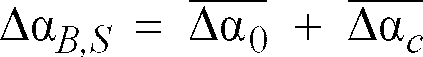
- the average of the current absolute angle of rotation determines:
Weiters wird
- das mittlere Lastmoment, mit dem der Motor betrieben wurde (

- the average load torque with which the motor was operated (
Zur aktuellen Nachkalibrierung der Federkonstanten geht man bei der Differenzwinkelmessung über ein linear-elastisches Element vom Hook'schen Gesetz aus:![]()
![]()
Wobei mit ![]()
![]()

![]()
![]()
Dabei wird für c der zuletzt gültige Wert der Federkonstanten eingesetzt.The last valid value of the spring constant is used for c.
Der Mittelwert aus diesen 5 Δα0-Werten bildet den Ausgangspunkt für die weitere laufende Kalibrierung:
In den folgenden Motorzyklen wird aus Gl. 21 iterativ der aktuelle c-Wert und dann wieder Δα0 bestimmt, und diese Werte werden vorzugsweise mit einer gewichteten Mittelwertbildung mit den jeweiligen Vergangenheitswerten verknüpft und so in bezug auf langsame Veränderungen der Federkonstanten ständig am aktuellen Stand gehalten.
Diese Adaptierung wird sofort unterbrochen, wenn die Bedingung der Periodizität von ΔαB,S über dem Motorzyklus nicht mehr erfüllt ist - also wenn Schlupf auftritt, was typischerweise beim Auskuppeln im Fahrzeugbetrieb geschieht. Dann werden die bisherigen Werte von Δα0 ungültig, der aktuelle Wert für die Federkonstante c stellt aber den Ausgangswert für den nächsten eingekuppelten Zustand dar. Die Überwachung eines allfälligen Kupplungsschlupfes kann bei Fahrzeuganwendungen vorteilhafterweise auch zur frühzeitigen Erkennung von Kupplungsverschleiß genutzt werden, und zwar dann, wenn bei andauernd hoher Last Schlupf festgestellt wird.The mean of these 5 Δα 0 values forms the starting point for the ongoing calibration:
In the following motor cycles, Eq. 21 iteratively determines the current c-value and then again Δα 0 , and these values are preferably linked to the respective past values by weighted averaging and are thus kept up to date with regard to slow changes in the spring constants.
This adaptation is interrupted immediately when the condition of the periodicity of Δα B, S over the engine cycle is no longer fulfilled - that is, when slip occurs, which typically occurs when the vehicle is disengaged. Then the previous values of Δα 0 become invalid, but the current value for the spring constant c represents the initial value for the next engaged state. The monitoring of a possible clutch slip can advantageously also be used in vehicle applications for the early detection of clutch wear, namely, if slippage is found under continuously high load.
Bei nichtlinearen elastischen Elementen werden Federkonstanten vorzugsweise in Abhängigkeit von der Höhe des Drehmomentes in der Kupplung
die Werte für Δ![]()

the values for Δ ![]()
Beispielsweise kann ein quadratisches Polynom angesetzt werden: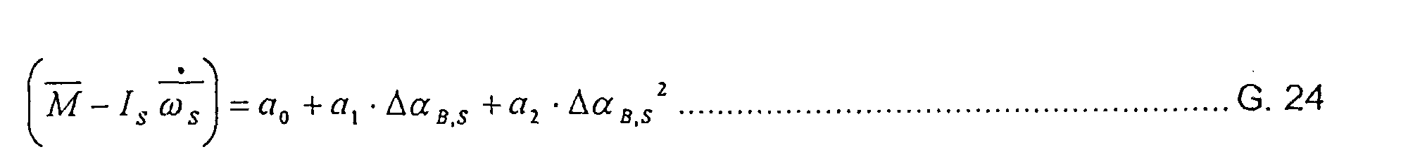
Aus dem Einpaßvorgang ergeben sich Werte für a0, a1 und a2.Values for a 0 , a 1 and a 2 result from the fitting process.
Als "Federkonstanten" für die entsprechenden

Die berechneten Federkonstanten werden in weiterer Folge als gewichtete Mittelwerte mit den Vergangenheitswerten abgespeichert. - Die Gültigkeit des Polynomkoeffizienten ist jeweils auf einen eingekuppelten Zustand eingeschränkt. Die Werte der Federkonstanten in Abhängigkeit von der augenblicklichen Motorlast bleiben dagegen gültig, bis im Hintergrund eine aktualisierte Kalibrierung abgeschlossen wurde. Damit ist auch im Fall des nichtlinearen, elastischen Zwischenelements eine fortlaufende Bestimmung des Einzelzylinderdrehmoments möglich. Diese Vorgangsweise ist natürlich auch im Falle von linear-elastischen Elementen anwendbar.The calculated spring constants are subsequently saved as weighted average values with the past values. - The validity of the polynomial coefficient is always limited to an engaged state. The values of the spring constants as a function of the current engine load, however, remain valid until an updated calibration is completed in the background has been. A continuous determination of the single cylinder torque is thus possible even in the case of the nonlinear, elastic intermediate element. This procedure can of course also be used in the case of linear-elastic elements.
Mit diesen selbstkalibrierenden Methoden kann also bereits aus zwei Winkelgeschwindigkeitsmessungen, und zwar vorzugsweise am Schwungrad und in Richtung Last nach einem elastischen Element (Zweimassenschwungrad, Kupplungsbelag, elastische Kupplung, lange Stahlwelle usw.) eine absolute Bewertung der Abweichungen in den Einzelzylinderdrehmomenten von deren Mittelwert realisiert werden, und zwar in so guter Qualität, daß damit auch eine Zylindergleichstellung möglich ist. Rückwirkungen vom Antriebsstrang her, wie beispielsweise "Ruckeln" oder Torsionsschwingungen, verfälschen das Ergebnis nicht.With these self-calibrating methods, an absolute evaluation of the deviations in the individual cylinder torques from their mean value can be realized from two angular velocity measurements, preferably on the flywheel and in the direction of the load after an elastic element (dual-mass flywheel, clutch lining, elastic coupling, long steel shaft, etc.) , and in such good quality that cylinder equality is also possible. Reactions from the drive train, such as "jerking" or torsional vibrations, do not falsify the result.
Die gleiche Methodik - die Kombination von Drehmoment - und Winkelgeschwindigkeitsmessung kann aber auch eingesetzt werden, wenn die Systemgrenze - und damit der Ort der Drehmomentmessung - unmittelbar vor das Schwungrad verlegt wird. Damit verlagert sich der Informationsgehalt über die Gaskraftwirkung zu einem größeren Teil in das Drehmomentensignal. Die Winkelgeschwindigkeit, gemessen an einem Ort, der starr mit der Drehmomentenmeßstelle verbunden ist, verliert an Bedeutung, was durch einen reduzierten Wert für das Motorträgheitsmoment - das Schwungrad ist dann ja außerhalb des betrachteten Systems - in die Gleichungen 9, 12 oder 14 Eingang findet.The same method - the combination of torque and angular velocity measurement can also be used if the system limit - and thus the location of the torque measurement - is moved directly in front of the flywheel. As a result, the information content on the gas force effect shifts to a greater extent into the torque signal. The angular velocity, measured at a location that is rigidly connected to the torque measuring point, loses importance, which is due to a reduced value for the engine moment of inertia - the flywheel is then outside the system under consideration - in
Diese Vorgangsweise bietet den Vorteil für,,on board"-Anwendungen, daß der Drehmomentsensor, vorzugsweise gleich kombiniert mit dem Winkelgeschwindigkeitssensor, direkt in die Kurbelwelle eingebaut werden kann. Dazu eignen sich beispielsweise Drehmomentmeßeinrichtung auf magnetisch induktiver Basis. Weiters kann das Auswerteverfahren in Hinblick auf Einzelzylinderleistung direkt in die Drehmomentenauswerteelektronik integriert werden, so daß dem Motormanagementsystem beispielsweise
- ein Signal für die Winkellage
- ein Signal für den Mittelwert des Drehmoments über einen Motorzyklus und
- ein Signal für das letzte Einzelzylinderdrehmoment
- a signal for the angular position
- a signal for the mean value of the torque over an engine cycle and
- a signal for the last single cylinder torque
Zur Gleichstellung von Einzelzylindereinspritzmengen wird weiters eine Einrichtung vorgestellt, die die Winkelgeschwindigkeit und das Drehmoment mißt.To equate single-cylinder injection quantities, a device is also presented that measures the angular velocity and the torque.
Dazu zeigt Fig. 6 eine bevorzugte Ausgestaltungsform, die hier beispielsweise in einem Regelkreis zur Gleichstellung von Einzelzylindereinspritzmengen eingesetzt wird:
Eine Brennkraftmaschine 1 treibt über ein Schwungrad 2 und über ein elastisches Zwischenelement 3 eine Belastungseinrichtung 4 an. Es werden sowohl schwungeradseitig 5 als auch lastseitig 6 vom elastischen Zwischenelement die Winkelverläufe (ca. 30 bis 200 Marken) sowie jeweils eine Bezugsmarke (Trigger oder ein unregelmäßiger Markenabstand) zeitlich vermessen.
In einer Winkelgeschwindigkeitsberechnungseinheit 7 und in einer Drehmomentenberechnungseinheit 8 werden die Ausgangswerte zur Berechnung der Einzelzylinderdrehmomentwerte bereitgestellt. Dabei wird in der Selbstkalibriereinrichtung 9 fortlaufend die Federkonstante aktualisiert und der Schlupf überwacht. Über eine Datenschnittstelle 14 zur Motorsteuerungselektronik 13 kann sowohl "unüblicher Schlupf" gemeldet als auch "der aktuelle mittlere Drehmomentenwert" erhalten werden. Weiters wird in einer Einzelzylinderdrehmomentenberechnungseinheit 10 eine Diagnosekenngröße berechnet, die vorzugsweise noch mit einem Korrekturkennfeld 11 um zylinderspezifische Fehler bereinigt wird, sodaß man für jeden Zylinder ein Einzelzylinderdrehmomentenmaß 12 erhält. Dieses Maß ist so genau, daß es beispielsweise ohne weiteres mit Hilfe der Motorsteuerungselekronik 13 dazu eingesetzt werden kann, die Signale zur Kraftstoffmengenansteuerung für jeden Zylinder 15 zu regeln.6 shows a preferred embodiment, which is used here, for example, in a control circuit for equalizing single-cylinder injection quantities:
An
The output values for calculating the single cylinder torque values are provided in an angular
Claims (17)
Applications Claiming Priority (3)
| Application Number | Priority Date | Filing Date | Title |
|---|---|---|---|
| AT338/95 | 1995-02-24 | ||
| AT33895 | 1995-06-22 | ||
| AT0033895U AT755U1 (en) | 1995-06-22 | 1995-06-22 | METHOD AND DEVICE FOR DIAGNOSING MULTI-CYLINDER INTERNAL COMBUSTION ENGINES |
Publications (3)
| Publication Number | Publication Date |
|---|---|
| EP0750184A2 true EP0750184A2 (en) | 1996-12-27 |
| EP0750184A3 EP0750184A3 (en) | 1997-06-18 |
| EP0750184B1 EP0750184B1 (en) | 2001-12-05 |
Family
ID=3487944
Family Applications (1)
| Application Number | Title | Priority Date | Filing Date |
|---|---|---|---|
| EP96890107A Expired - Lifetime EP0750184B1 (en) | 1995-06-22 | 1996-06-19 | Method and apparatus for diagnosing a multi-cylinder internal combustion engine |
Country Status (3)
| Country | Link |
|---|---|
| EP (1) | EP0750184B1 (en) |
| AT (2) | AT755U1 (en) |
| DE (1) | DE59608341D1 (en) |
Cited By (6)
| Publication number | Priority date | Publication date | Assignee | Title |
|---|---|---|---|---|
| EP1058108A2 (en) | 1999-05-31 | 2000-12-06 | AVL List GmbH | Method and apparatus for diagnosing and controlling an internal combustion engine |
| WO2001065225A2 (en) * | 2000-03-02 | 2001-09-07 | Siemens Automotive Corporation | Engine torque sensor |
| CN103389210A (en) * | 2013-07-08 | 2013-11-13 | 潍柴动力股份有限公司 | Elastomer vibration reducing performance detecting method |
| DE102013220413A1 (en) * | 2013-10-10 | 2015-04-16 | Continental Automotive Gmbh | Method for diagnosing a combustion engine coupled to an electric machine by a shaft and diagnostic device |
| DE112007003038B4 (en) * | 2007-01-05 | 2019-11-21 | Schaeffler Technologies AG & Co. KG | powertrain |
| DE112007003032B4 (en) * | 2007-01-05 | 2019-12-12 | Schaeffler Technologies AG & Co. KG | powertrain |
Citations (6)
| Publication number | Priority date | Publication date | Assignee | Title |
|---|---|---|---|---|
| EP0434665A1 (en) * | 1989-12-22 | 1991-06-26 | AVL Gesellschaft für Verbrennungskraftmaschinen und Messtechnik mbH.Prof.Dr.Dr.h.c. Hans List | Method and device for diagnosis of an internal combustion engine |
| EP0469658A2 (en) * | 1990-07-30 | 1992-02-05 | General Motors Corporation | Method of analysing cylinder performance in an internal combustion engine |
| DE4028131A1 (en) * | 1990-09-05 | 1992-03-12 | Bosch Gmbh Robert | METHOD FOR DETECTING FAILURE IN AN INTERNAL COMBUSTION ENGINE |
| US5109696A (en) * | 1990-09-06 | 1992-05-05 | Caterpillar Inc. | Powertrain performance assessment system |
| US5313826A (en) * | 1990-12-10 | 1994-05-24 | Sensortech L.P. | Engine misfire, knock or roughness detection method and apparatus |
| US5353636A (en) * | 1992-08-07 | 1994-10-11 | Toyota Jidosha Kabushiki Kaisha | Device for determining misfiring of cylinders in multi-cylinder engines |
-
1995
- 1995-06-22 AT AT0033895U patent/AT755U1/en not_active IP Right Cessation
-
1996
- 1996-06-19 AT AT96890107T patent/ATE210286T1/en not_active IP Right Cessation
- 1996-06-19 DE DE59608341T patent/DE59608341D1/en not_active Expired - Lifetime
- 1996-06-19 EP EP96890107A patent/EP0750184B1/en not_active Expired - Lifetime
Patent Citations (6)
| Publication number | Priority date | Publication date | Assignee | Title |
|---|---|---|---|---|
| EP0434665A1 (en) * | 1989-12-22 | 1991-06-26 | AVL Gesellschaft für Verbrennungskraftmaschinen und Messtechnik mbH.Prof.Dr.Dr.h.c. Hans List | Method and device for diagnosis of an internal combustion engine |
| EP0469658A2 (en) * | 1990-07-30 | 1992-02-05 | General Motors Corporation | Method of analysing cylinder performance in an internal combustion engine |
| DE4028131A1 (en) * | 1990-09-05 | 1992-03-12 | Bosch Gmbh Robert | METHOD FOR DETECTING FAILURE IN AN INTERNAL COMBUSTION ENGINE |
| US5109696A (en) * | 1990-09-06 | 1992-05-05 | Caterpillar Inc. | Powertrain performance assessment system |
| US5313826A (en) * | 1990-12-10 | 1994-05-24 | Sensortech L.P. | Engine misfire, knock or roughness detection method and apparatus |
| US5353636A (en) * | 1992-08-07 | 1994-10-11 | Toyota Jidosha Kabushiki Kaisha | Device for determining misfiring of cylinders in multi-cylinder engines |
Cited By (11)
| Publication number | Priority date | Publication date | Assignee | Title |
|---|---|---|---|---|
| EP1058108A2 (en) | 1999-05-31 | 2000-12-06 | AVL List GmbH | Method and apparatus for diagnosing and controlling an internal combustion engine |
| EP1058108A3 (en) * | 1999-05-31 | 2002-07-24 | AVL List GmbH | Method and apparatus for diagnosing and controlling an internal combustion engine |
| WO2001065225A2 (en) * | 2000-03-02 | 2001-09-07 | Siemens Automotive Corporation | Engine torque sensor |
| WO2001065225A3 (en) * | 2000-03-02 | 2002-01-31 | Siemens Automotive Corp Lp | Engine torque sensor |
| US6901815B2 (en) | 2000-03-02 | 2005-06-07 | Siemens Vdo Automotive Corporation | Engine torque sensor |
| DE112007003038B4 (en) * | 2007-01-05 | 2019-11-21 | Schaeffler Technologies AG & Co. KG | powertrain |
| DE112007003032B4 (en) * | 2007-01-05 | 2019-12-12 | Schaeffler Technologies AG & Co. KG | powertrain |
| CN103389210A (en) * | 2013-07-08 | 2013-11-13 | 潍柴动力股份有限公司 | Elastomer vibration reducing performance detecting method |
| CN103389210B (en) * | 2013-07-08 | 2016-12-28 | 潍柴动力股份有限公司 | Elastomer damping property detection method |
| DE102013220413A1 (en) * | 2013-10-10 | 2015-04-16 | Continental Automotive Gmbh | Method for diagnosing a combustion engine coupled to an electric machine by a shaft and diagnostic device |
| DE102013220413B4 (en) * | 2013-10-10 | 2017-02-02 | Continental Automotive Gmbh | A method of diagnosing misfiring of an internal combustion engine coupled to an electrical machine by a shaft and a diagnostic device |
Also Published As
| Publication number | Publication date |
|---|---|
| AT755U1 (en) | 1996-04-25 |
| ATE210286T1 (en) | 2001-12-15 |
| DE59608341D1 (en) | 2002-01-17 |
| EP0750184B1 (en) | 2001-12-05 |
| EP0750184A3 (en) | 1997-06-18 |
Similar Documents
| Publication | Publication Date | Title |
|---|---|---|
| EP0434665B1 (en) | Method and device for diagnosis of an internal combustion engine | |
| EP1525382B1 (en) | Regulating the mode of operation of an internal combustion engine | |
| DE102012106480B4 (en) | Method for controlling the combustion of a diesel engine | |
| DE112009001445B4 (en) | Fuel system injection timing diagnosis by analyzing the cylinder pressure signal | |
| DE4407167C2 (en) | Method for determining operating parameters of an internal combustion engine by evaluating the speed information | |
| DE112007003038B4 (en) | powertrain | |
| DE4445684C2 (en) | Procedure for determining torques, work and performance on internal combustion engines | |
| WO2005083252A1 (en) | Method and device for detecting the angular position signal in an internal combustion engine | |
| EP1921297A1 (en) | Method for determining the cylinder pressure in a combustion engine | |
| DE102005035408A1 (en) | Method for determining cylinder-specific rotational characteristics of a shaft of an internal combustion engine | |
| DE10356133A1 (en) | Diesel engine combustion engine combustion initiation time measurement procedure uses acceleration value from differentiated crank shaft angular velocity meaurement | |
| DE102015102249A1 (en) | Method and device for determining the power distribution of an internal combustion engine | |
| DE4435654C2 (en) | Device for detecting an operating state, in particular misfiring of a motor vehicle, and detection method therefor | |
| EP0750184B1 (en) | Method and apparatus for diagnosing a multi-cylinder internal combustion engine | |
| DE102012110028B4 (en) | Learning device for an internal combustion engine | |
| DE102009013409A1 (en) | Drive chain particularly for motor vehicle, has drive unit controlled by control unit with multiple cylinders and drive shaft, and condition value of dual mass flywheel is read in controller | |
| DE19941171B4 (en) | Method for determining the torque applied by an internal combustion engine | |
| EP0592628B1 (en) | Method for monitoring engine torque | |
| DE3917905A1 (en) | IC engine efficiency optimisation system - uses detected engine knock and monitored air of engine cylinder working vol to adjust ignition timing | |
| EP1058108B1 (en) | Method and apparatus for diagnosing and controlling an internal combustion engine | |
| DE10256106B4 (en) | Apparatus and method for estimating engine torque | |
| DE102008044305B4 (en) | Method, control device and computer program product for detecting the uneven running of a multi-cylinder internal combustion engine | |
| DE102006003264A1 (en) | Estimating method e.g. for torque delivered by internal-combustion engine, involves determining torque of internal-combustion engine, and measurement made in crankshaft of change portion of gas moment | |
| WO2004040251A1 (en) | Measurement of the torque of an internal combustion engine on the basis of the bearing forces | |
| AT523036B1 (en) | PROCEDURE FOR ZERO ADJUSTMENT TO AT LEAST ONE SENSOR |
Legal Events
| Date | Code | Title | Description |
|---|---|---|---|
| PUAI | Public reference made under article 153(3) epc to a published international application that has entered the european phase |
Free format text: ORIGINAL CODE: 0009012 |
|
| AK | Designated contracting states |
Kind code of ref document: A2 Designated state(s): AT DE FR GB IT SE |
|
| RAP1 | Party data changed (applicant data changed or rights of an application transferred) |
Owner name: AVL LIST GMBH |
|
| PUAL | Search report despatched |
Free format text: ORIGINAL CODE: 0009013 |
|
| AK | Designated contracting states |
Kind code of ref document: A3 Designated state(s): AT DE FR GB IT SE |
|
| 17P | Request for examination filed |
Effective date: 19971022 |
|
| 17Q | First examination report despatched |
Effective date: 20000530 |
|
| GRAG | Despatch of communication of intention to grant |
Free format text: ORIGINAL CODE: EPIDOS AGRA |
|
| GRAG | Despatch of communication of intention to grant |
Free format text: ORIGINAL CODE: EPIDOS AGRA |
|
| GRAH | Despatch of communication of intention to grant a patent |
Free format text: ORIGINAL CODE: EPIDOS IGRA |
|
| GRAH | Despatch of communication of intention to grant a patent |
Free format text: ORIGINAL CODE: EPIDOS IGRA |
|
| GRAA | (expected) grant |
Free format text: ORIGINAL CODE: 0009210 |
|
| AK | Designated contracting states |
Kind code of ref document: B1 Designated state(s): AT DE FR GB IT SE |
|
| REF | Corresponds to: |
Ref document number: 210286 Country of ref document: AT Date of ref document: 20011215 Kind code of ref document: T |
|
| REG | Reference to a national code |
Ref country code: GB Ref legal event code: IF02 |
|
| GBT | Gb: translation of ep patent filed (gb section 77(6)(a)/1977) |
Effective date: 20011206 |
|
| REF | Corresponds to: |
Ref document number: 59608341 Country of ref document: DE Date of ref document: 20020117 |
|
| ET | Fr: translation filed | ||
| PLBE | No opposition filed within time limit |
Free format text: ORIGINAL CODE: 0009261 |
|
| STAA | Information on the status of an ep patent application or granted ep patent |
Free format text: STATUS: NO OPPOSITION FILED WITHIN TIME LIMIT |
|
| 26N | No opposition filed | ||
| PGFP | Annual fee paid to national office [announced via postgrant information from national office to epo] |
Ref country code: AT Payment date: 20080623 Year of fee payment: 13 |
|
| PGFP | Annual fee paid to national office [announced via postgrant information from national office to epo] |
Ref country code: IT Payment date: 20080625 Year of fee payment: 13 |
|
| PGFP | Annual fee paid to national office [announced via postgrant information from national office to epo] |
Ref country code: SE Payment date: 20080609 Year of fee payment: 13 |
|
| PGFP | Annual fee paid to national office [announced via postgrant information from national office to epo] |
Ref country code: FR Payment date: 20080611 Year of fee payment: 13 |
|
| PGFP | Annual fee paid to national office [announced via postgrant information from national office to epo] |
Ref country code: GB Payment date: 20080620 Year of fee payment: 13 |
|
| GBPC | Gb: european patent ceased through non-payment of renewal fee |
Effective date: 20090619 |
|
| REG | Reference to a national code |
Ref country code: FR Ref legal event code: ST Effective date: 20100226 |
|
| PG25 | Lapsed in a contracting state [announced via postgrant information from national office to epo] |
Ref country code: FR Free format text: LAPSE BECAUSE OF NON-PAYMENT OF DUE FEES Effective date: 20090630 |
|
| PG25 | Lapsed in a contracting state [announced via postgrant information from national office to epo] |
Ref country code: GB Free format text: LAPSE BECAUSE OF NON-PAYMENT OF DUE FEES Effective date: 20090619 |
|
| PG25 | Lapsed in a contracting state [announced via postgrant information from national office to epo] |
Ref country code: AT Free format text: LAPSE BECAUSE OF NON-PAYMENT OF DUE FEES Effective date: 20090619 |
|
| PG25 | Lapsed in a contracting state [announced via postgrant information from national office to epo] |
Ref country code: IT Free format text: LAPSE BECAUSE OF NON-PAYMENT OF DUE FEES Effective date: 20090619 |
|
| PG25 | Lapsed in a contracting state [announced via postgrant information from national office to epo] |
Ref country code: SE Free format text: LAPSE BECAUSE OF NON-PAYMENT OF DUE FEES Effective date: 20090620 |
|
| PGFP | Annual fee paid to national office [announced via postgrant information from national office to epo] |
Ref country code: DE Payment date: 20120703 Year of fee payment: 17 |
|
| REG | Reference to a national code |
Ref country code: DE Ref legal event code: R119 Ref document number: 59608341 Country of ref document: DE Effective date: 20140101 |
|
| PG25 | Lapsed in a contracting state [announced via postgrant information from national office to epo] |
Ref country code: DE Free format text: LAPSE BECAUSE OF NON-PAYMENT OF DUE FEES Effective date: 20140101 |