EP0750184A2 - Procédé et dispositif pour le diagnostic des moteurs polycylindriques à combustion interne - Google Patents
Procédé et dispositif pour le diagnostic des moteurs polycylindriques à combustion interne Download PDFInfo
- Publication number
- EP0750184A2 EP0750184A2 EP96890107A EP96890107A EP0750184A2 EP 0750184 A2 EP0750184 A2 EP 0750184A2 EP 96890107 A EP96890107 A EP 96890107A EP 96890107 A EP96890107 A EP 96890107A EP 0750184 A2 EP0750184 A2 EP 0750184A2
- Authority
- EP
- European Patent Office
- Prior art keywords
- internal combustion
- cylinder
- combustion engine
- diagnostic
- diagnostic method
- Prior art date
- Legal status (The legal status is an assumption and is not a legal conclusion. Google has not performed a legal analysis and makes no representation as to the accuracy of the status listed.)
- Granted
Links
Images


Classifications
-
- G—PHYSICS
- G01—MEASURING; TESTING
- G01M—TESTING STATIC OR DYNAMIC BALANCE OF MACHINES OR STRUCTURES; TESTING OF STRUCTURES OR APPARATUS, NOT OTHERWISE PROVIDED FOR
- G01M15/00—Testing of engines
- G01M15/04—Testing internal-combustion engines
- G01M15/042—Testing internal-combustion engines by monitoring a single specific parameter not covered by groups G01M15/06 - G01M15/12
- G01M15/046—Testing internal-combustion engines by monitoring a single specific parameter not covered by groups G01M15/06 - G01M15/12 by monitoring revolutions
-
- F—MECHANICAL ENGINEERING; LIGHTING; HEATING; WEAPONS; BLASTING
- F02—COMBUSTION ENGINES; HOT-GAS OR COMBUSTION-PRODUCT ENGINE PLANTS
- F02D—CONTROLLING COMBUSTION ENGINES
- F02D2200/00—Input parameters for engine control
- F02D2200/02—Input parameters for engine control the parameters being related to the engine
- F02D2200/10—Parameters related to the engine output, e.g. engine torque or engine speed
- F02D2200/1015—Engines misfires
Definitions
- the invention relates to a diagnostic method for multi-cylinder internal combustion engines, wherein angular velocities are recorded for at least one crank-driven component of the internal combustion engine for defined crank angle positions, and from this, taking into account the respectively effective total moment of inertia, the respective total energies or diagnostic parameters represented thereby, such as in particular single-cylinder power quantities or single-cylinder load variables, be determined. Furthermore, the invention also relates to a method for the initial adjustment or for the adjustment if necessary of an internal combustion engine checked by means of such a diagnostic method.
- the invention also relates to a device for diagnosing multi-cylinder internal combustion engines, with at least one measuring unit for determining angular velocities on a crank-driven component of the internal combustion engine and an associated evaluation unit, in which, taking into account crank angle-dependent total moments of inertia, diagnostic parameters, such as, in particular, single-cylinder power parameters or Single cylinder load sizes can be determined.
- EP-A-0 434 665 it is known to determine a single cylinder power measure based on one or more angular velocity profiles (at several locations on the shaft train) using the so-called energy level method from the profile of the stored kinetic energy.
- the influence of the mass force and the influence of torsional vibrations are taken into account and, on the other hand, a so-called mixed effective mean pressure is calculated as a measurement, which allows small changes in individual cylinder power values to be recognized and not just the total failure of a cylinder, for example.
- the disadvantage is that only those torsional vibrations can be compensated for that run within the intended system limits.
- the object of the present invention is to improve methods and devices of the type mentioned at the outset in such a way that the disadvantages mentioned of the known methods and devices are avoided and in particular, for example, that the accuracy of the diagnostic parameters determined for the single-cylinder evaluation can be increased in such a way that not only misfire detection, but also a direct control of the amount of fuel supplied to the individual cylinders is made possible.
- This task is also to be solved not only at idling but also at all engine speeds, particularly in the full-load range, which is particularly advantageous, for example, in diesel internal combustion engines, which with full load minimal excess air can be operated. If this minimum air excess value in individual cylinders is undershot, the undesirable emission of pollutants increases disproportionately.
- the stated object is achieved in a diagnostic method of the type mentioned at the outset in that, in addition to the angular velocity measurement (s), at least one rotational angle or time-resolved torque measurement is carried out on an output-side system boundary and the respective energy transport represented thereby System limit is taken into account when determining the diagnostic parameters.
- the device according to the invention for diagnosing multi-cylinder internal combustion engines is accordingly characterized in that at least one further measuring unit for measuring the angle of rotation or time-resolved torque is provided on a system boundary on the output side and is likewise connected to the evaluation unit.
- the additional instantaneous measurement - preferably according to the flywheel of the internal combustion engine - makes the associated instantaneous Energy transport recorded over this system boundary and billed. This advantageously makes one directly independent of the assumption that the torque on the flywheel is periodic in the ignition interval. This is not the case if, e.g. Torsional vibrations occur in the drive train, or feedback effects from an uneven roadway or the like require a strongly fluctuating torque from the internal combustion engine.
- the invention thus represents an essential improvement or generalization of the above-mentioned "energy level method".
- This is versatile - and not only usable for single-cylinder power measurement
- the calculation of the energy currently stored in the respective system is improved by evaluating not only the energy level curve according to the prior art but also a torque curve at a system limit. In this way, fluctuations in the drive train torsion and the load torque that reacts from the outside of the internal combustion engine can be taken into account, so that the corrected energy level curve obtained is determined practically exclusively by the acting gas forces and the friction.
- a number of diagnostic variables such as those e.g. can be derived in the indexing technique from the entirety of the measured combustion chamber pressure curves of all cylinders or are causally related to them.
- the corrected energy level curve mentioned or the corresponding curve of the corrected torque contains diagnostic information about the entire internal combustion engine and at the same time also about the individual cylinders; among other things with regard to torque or power, friction torque or power, compression and charge changes. Diagnostic statements can be made about all these "cylinder pressure effects" using the method or the corresponding device improved according to the invention, which is particularly important for production test applications by considering the corrected course of the stored energy or its derivation.
- the respective angle of rotation between a flywheel arranged on the crankshaft of the internal combustion engine and a downstream load device is measured and evaluated together with the spring constant of an elastic drive train element located between the flywheel and load device.
- the spring constants can preferably be calibrated using the mean angle of rotation and an additional measure for the mean value of the engine load.
- the angle of rotation measurement for torque measurement can also be carried out via a clutch lining, with early clutch wear being diagnosed in the event of permanent slippage under high load. In this way, additional diagnostic statements that go beyond the cylinder pressure effects mentioned can also be obtained.
- difference profiles between the profiles of the corrected diagnostic parameters of the respectively tested internal combustion engine and an internal combustion engine which has been found to be good are evaluated, statistical aids - such as e.g. Good condition scatter bands - can be used.
- the recorded flywheel angular velocity is low-pass filtered.
- the result variable can also be corrected using a correction map after the calculation of a single-cylinder torque measure which was initially falsified by high-frequency crankshaft torsional vibrations and which was calculated solely from the flywheel angular velocity and the torque measurement.
- This correction map only has to be created once for each engine type-clutch combination.
- Different individual cylinder torque contributions influence the excitation state in the low frequency range in which the clutch torsional vibrations occur.
- the severity of the coupling torsional vibrations and thus their falsifying influence on the result size depends on whether the cylinders work evenly - or not. This means that the correction map must also depend on it so that it cannot be determined once.
- misfires of individual cylinders can be determined from the courses of corrected single-cylinder diagnostic parameters.
- a further embodiment is advantageous for evaluating or increasing the significance of the diagnostic method according to the invention, according to which at least one angular velocity curve is recorded in the region of a modal vibration node of the crankshaft.
- an adaptive setting of parameters and / or target values of the control or regulation is carried out with the aid of the corrected single-cylinder diagnostic parameters determined on-board.
- a further embodiment of the device according to the invention is finally characterized accordingly by a connection to an engine management system for adaptively setting parameters and / or target values for the control or regulation of the internal combustion engine.
- a single cylinder torque can thus be determined very easily in accordance with the invention, which is very important, for example, for the on-board applications mentioned for "cylinder equalization".
- This single-cylinder torque also allows, in particular, diagnostic conclusions to be drawn about the general function of the injection system of an internal combustion engine, the amount of fuel injected itself, and possible misfires.
- Preferred areas of application for the described method configurations according to the invention or the corresponding devices are production test benches with a towed internal combustion engine (cold test), production test benches with a fired internal combustion engine and on-board applications.
- testing is generally carried out while the internal combustion engine is idling, so that the simple, uncorrected energy level method according to the prior art will usually be sufficient there.
- the aforementioned initial setting of an internal combustion engine can take place on the production test bench; on the other hand - expediently using on-board devices for determining E ( ⁇ ) and / or M ( ⁇ ) - the internal combustion engine can be readjusted (occasionally, periodically, continuously), regulation (possibly adaptive) or diagnosis become.
- E ( ⁇ ) and / or M ( ⁇ ) - the internal combustion engine can be readjusted (occasionally, periodically, continuously), regulation (possibly adaptive) or diagnosis become.
- the "corrected energy level curves” either absolute parameters can be determined or relative parameters of the internal combustion engine to be tested on the one hand and the known internal combustion engine on the other hand can be in good condition.
- differential courses and / or differential parameters of unknown and known (good) can be calculated or statistical methods and dimensions such as scatter bands, reliability ranges, etc. can be used.
- the additionally determined torque serving for the mentioned correction can be determined with conventional, known torque sensors or - in any case known per se - can be determined from the angle of rotation of a torsionally elastic part of the drive train.
- the spring constants are calibrated from a known average engine load, so that the required dynamic portion of the engine torque can be determined with existing low-quality components, without having to use high-precision, expensive and space-consuming torque measuring shafts or the like. It should be noted that such a linear calibration essentially only applies in the area of the relevant working point (load point) if the spring line itself is not linear.
- the slip must also be monitored or excluded and in particular the shaft rotation when disengaging must also be taken into account. If, on the other hand, there is residual slip after engaging, this indicates that the clutch is worn.
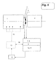
- FIG. 6 shows a preferred device in which the method for controlling single cylinder injection quantities is used.
- the torque signal is calculated in a self-calibrating manner from two angular velocity signals - on both sides of the elastic intermediate element between the flywheel and the load device.
- Figure 1 shows the delimitation of the system under consideration. Accordingly, the internal combustion engine is separated immediately after the flywheel from the rest of the drive train - in the case of the example: from the test bench brake.
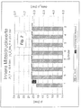
- Figure 2 shows values for indexed mean pressures of an 8 cylinder truck engine.
- the cylinder pressure curve of cylinder 1 was multiplied by 0.95, so that the pi value for cylinder 1 - compared to the pi values of cylinders 2 to 8, which are all the same - was also reduced by 5%.
- delta_pi the common mean in bar form
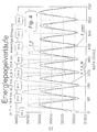
- E_S does not correctly represent the course of the stored energy: torsional vibrations in the crankshaft falsify the amplitude in the ignition frequency and torsional vibrations in the clutch - stimulated by the non-uniform load torque - even cause an energy increase in the expansion range of cylinder 1, which in this example is 5% weaker than the others.
- Such a 2-mass distribution can be understood as an approximation for the real torsional vibration system, which has significantly more partial masses and degrees of freedom.
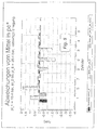
- FIG. 5 shows that, especially for evaluating deviations in the individual cylinder power - for example for equalizing injection quantities - the combined evaluation of angular velocity and torque achieves decisive advantages in accuracy, so that an application in control systems is possible in the first place.
- the accuracy of the results can be increased even further by correcting cylinder-specific errors that primarily depend on the operating state (e.g. remaining errors as a result of high-frequency torsional vibrations) via an engine-specific correction map.
- E total ( ⁇ OTj) I. ⁇ s ⁇ ⁇ ⁇ s j 2nd 2nd
- I. S ⁇ Mean of I S according to Eq. 7 - - maximum in the interval of ⁇ OTj - Firing interval 2nd to ⁇ OTj + Firing interval 2nd
- ⁇ sj ⁇ Mean of ⁇ s ( ⁇ ) - maximum in the interval of ⁇ OTj - Firing interval 2nd to ⁇ OTj + Firing interval 2nd
- the size is absolutely comparable with deviations in the indicated medium pressure [bar] and is furthermore not restricted to any special operating conditions of the internal combustion engine.
- a fluctuating load torque is e.g. also given in ship engines, and not only in the auxiliary units, for example for driving compressors or pumps, but also in the main drive motors.
- Load, swell and water depth are factors that influence the propeller characteristics, so that the propeller load is not a clear function of the speed, both on the high seas and in coastal and inland waters.
- the method presented here can therefore also be used to advantage in this area, for example in a device with which the individual cylinder output is continuously monitored and / or set within certain limits.
- the spring characteristic is basically known about the angle of rotation of the elastic element, but can change slowly over the course of years of use or with the temperature.
- the spring constant is continuously determined using the following method:
- the current recalibration of the spring constant is based on Hook's law when measuring the differential angle using a linear-elastic element :
- Eq. 21 iteratively determines the current c-value and then again ⁇ 0 , and these values are preferably linked to the respective past values by weighted averaging and are thus kept up to date with regard to slow changes in the spring constants.
- This adaptation is interrupted immediately when the condition of the periodicity of ⁇ B, S over the engine cycle is no longer fulfilled - that is, when slip occurs, which typically occurs when the vehicle is disengaged. Then the previous values of ⁇ 0 become invalid, but the current value for the spring constant c represents the initial value for the next engaged state.
- the monitoring of a possible clutch slip can advantageously also be used in vehicle applications for the early detection of clutch wear, namely, if slippage is found under continuously high load.
- spring constants are preferably dependent on the amount of torque in the coupling saved.
- the following is suggested as a procedure for the recalibration: the values for ⁇ ⁇ B, S ⁇ and are recorded over a large number of work cycles (e.g. 200) after each engagement process, with a corresponding number of value pairs (in each case approx. 25% of the total number) being present at least for low and high loads.
- a polynomial which corresponds to the basic characteristic of the coupling is fitted into this set of points, for example using the "least squares method":
- a quadratic polynomial can be used:
- the calculated spring constants are subsequently saved as weighted average values with the past values. -
- the validity of the polynomial coefficient is always limited to an engaged state.
- the values of the spring constants as a function of the current engine load remain valid until an updated calibration is completed in the background has been. A continuous determination of the single cylinder torque is thus possible even in the case of the nonlinear, elastic intermediate element. This procedure can of course also be used in the case of linear-elastic elements.
- a device that measures the angular velocity and the torque.
- FIG. 6 shows a preferred embodiment, which is used here, for example, in a control circuit for equalizing single-cylinder injection quantities:
- An internal combustion engine 1 drives a load device 4 via a flywheel 2 and an elastic intermediate element 3.
- the angle gradients (approx. 30 to 200 marks) and a reference mark (trigger or an irregular mark spacing) are measured in time on both the flywheel side 5 and the load side 6 of the elastic intermediate element.
- the output values for calculating the single cylinder torque values are provided in an angular velocity calculation unit 7 and in a torque calculation unit 8.
- the spring constant is continuously updated in the self-calibration device 9 and the slip is monitored. Via a data interface 14 to the engine control electronics 13, both "unusual slip" can be reported and "the current average torque value" can be obtained.
- a diagnostic parameter is calculated in a single-cylinder torque calculation unit 10, which is preferably also corrected for cylinder-specific errors with a correction map 11, so that a single-cylinder torque measure 12 is obtained for each cylinder.
- This dimension is so precise that it can be used, for example, with the help of the engine control electronics 13 to regulate the signals for fuel quantity control for each cylinder 15.
Landscapes
- Chemical & Material Sciences (AREA)
- Engineering & Computer Science (AREA)
- Combustion & Propulsion (AREA)
- Physics & Mathematics (AREA)
- General Physics & Mathematics (AREA)
- Testing Of Engines (AREA)
- Combined Controls Of Internal Combustion Engines (AREA)
Applications Claiming Priority (3)
| Application Number | Priority Date | Filing Date | Title |
|---|---|---|---|
| AT338/95 | 1995-02-24 | ||
| AT33895 | 1995-06-22 | ||
| AT0033895U AT755U1 (de) | 1995-06-22 | 1995-06-22 | Verfahren und einrichtung zur diagnose mehrzylindriger brennkraftmaschinen |
Publications (3)
| Publication Number | Publication Date |
|---|---|
| EP0750184A2 true EP0750184A2 (fr) | 1996-12-27 |
| EP0750184A3 EP0750184A3 (fr) | 1997-06-18 |
| EP0750184B1 EP0750184B1 (fr) | 2001-12-05 |
Family
ID=3487944
Family Applications (1)
| Application Number | Title | Priority Date | Filing Date |
|---|---|---|---|
| EP96890107A Expired - Lifetime EP0750184B1 (fr) | 1995-06-22 | 1996-06-19 | Procédé et dispositif pour le diagnostic des moteurs polycylindriques à combustion interne |
Country Status (3)
| Country | Link |
|---|---|
| EP (1) | EP0750184B1 (fr) |
| AT (2) | AT755U1 (fr) |
| DE (1) | DE59608341D1 (fr) |
Cited By (6)
| Publication number | Priority date | Publication date | Assignee | Title |
|---|---|---|---|---|
| EP1058108A2 (fr) | 1999-05-31 | 2000-12-06 | AVL List GmbH | Méthode et appareil pour le diagnositic et la commande d'un moteur à combustion interne |
| WO2001065225A3 (fr) * | 2000-03-02 | 2002-01-31 | Siemens Automotive Corp Lp | Capteur de couple moteur |
| CN103389210A (zh) * | 2013-07-08 | 2013-11-13 | 潍柴动力股份有限公司 | 弹性体减振性能检测方法 |
| DE102013220413A1 (de) * | 2013-10-10 | 2015-04-16 | Continental Automotive Gmbh | Verfahren zur Diagnose eines durch eine Welle mit einer elektrischen Maschine gekoppelten Verbrennungsmotors sowie Diagnoseeinrichtung |
| DE112007003038B4 (de) * | 2007-01-05 | 2019-11-21 | Schaeffler Technologies AG & Co. KG | Antriebsstrang |
| DE112007003032B4 (de) * | 2007-01-05 | 2019-12-12 | Schaeffler Technologies AG & Co. KG | Antriebsstrang |
Family Cites Families (6)
| Publication number | Priority date | Publication date | Assignee | Title |
|---|---|---|---|---|
| AT393324B (de) * | 1989-12-22 | 1991-09-25 | Avl Verbrennungskraft Messtech | Verfahren und einrichtung zur diagnose von brennkraftmaschinen |
| US5132909A (en) * | 1990-07-30 | 1992-07-21 | Saturn Corporation | Apparatus for diagnosing individual cylinder performance by estimated instantaneous engine speeds |
| DE4028131C2 (de) * | 1990-09-05 | 2001-06-13 | Bosch Gmbh Robert | Verfahren zur Aussetzererkennung in einem Verbrennungsmotor |
| US5109696A (en) * | 1990-09-06 | 1992-05-05 | Caterpillar Inc. | Powertrain performance assessment system |
| US5269178A (en) * | 1990-12-10 | 1993-12-14 | Sensortech, L.P. | Engine misfire, knock of roughness detection method and apparatus |
| JP3315724B2 (ja) * | 1992-08-07 | 2002-08-19 | トヨタ自動車株式会社 | 失火検出装置 |
-
1995
- 1995-06-22 AT AT0033895U patent/AT755U1/de not_active IP Right Cessation
-
1996
- 1996-06-19 AT AT96890107T patent/ATE210286T1/de not_active IP Right Cessation
- 1996-06-19 EP EP96890107A patent/EP0750184B1/fr not_active Expired - Lifetime
- 1996-06-19 DE DE59608341T patent/DE59608341D1/de not_active Expired - Lifetime
Cited By (10)
| Publication number | Priority date | Publication date | Assignee | Title |
|---|---|---|---|---|
| EP1058108A2 (fr) | 1999-05-31 | 2000-12-06 | AVL List GmbH | Méthode et appareil pour le diagnositic et la commande d'un moteur à combustion interne |
| EP1058108A3 (fr) * | 1999-05-31 | 2002-07-24 | AVL List GmbH | Méthode et appareil pour le diagnositic et la commande d'un moteur à combustion interne |
| WO2001065225A3 (fr) * | 2000-03-02 | 2002-01-31 | Siemens Automotive Corp Lp | Capteur de couple moteur |
| US6901815B2 (en) | 2000-03-02 | 2005-06-07 | Siemens Vdo Automotive Corporation | Engine torque sensor |
| DE112007003038B4 (de) * | 2007-01-05 | 2019-11-21 | Schaeffler Technologies AG & Co. KG | Antriebsstrang |
| DE112007003032B4 (de) * | 2007-01-05 | 2019-12-12 | Schaeffler Technologies AG & Co. KG | Antriebsstrang |
| CN103389210A (zh) * | 2013-07-08 | 2013-11-13 | 潍柴动力股份有限公司 | 弹性体减振性能检测方法 |
| CN103389210B (zh) * | 2013-07-08 | 2016-12-28 | 潍柴动力股份有限公司 | 弹性体减振性能检测方法 |
| DE102013220413A1 (de) * | 2013-10-10 | 2015-04-16 | Continental Automotive Gmbh | Verfahren zur Diagnose eines durch eine Welle mit einer elektrischen Maschine gekoppelten Verbrennungsmotors sowie Diagnoseeinrichtung |
| DE102013220413B4 (de) * | 2013-10-10 | 2017-02-02 | Continental Automotive Gmbh | Verfahren zur Diagnose von Verbrennungsaussetzern eines durch eine Welle mit einer elektrischen Maschine gekoppelten Verbrennungsmotors sowie Diagnoseeinrichtung |
Also Published As
| Publication number | Publication date |
|---|---|
| EP0750184A3 (fr) | 1997-06-18 |
| AT755U1 (de) | 1996-04-25 |
| ATE210286T1 (de) | 2001-12-15 |
| EP0750184B1 (fr) | 2001-12-05 |
| DE59608341D1 (de) | 2002-01-17 |
Similar Documents
| Publication | Publication Date | Title |
|---|---|---|
| EP0434665B1 (fr) | Procédé et dispositif pour le diagnostic d'un moteur à combustion interne | |
| EP1525382B1 (fr) | Reglage du mode de fonctionnement d'un moteur a combustion interne | |
| DE102012106480B4 (de) | Verfahren zum Steuern der Verbrennung eines Dieselmotors | |
| DE112009001445B4 (de) | Kraftstoffsystem-Einspritzzeiteinstellungsdiagnose durch Analysieren des Zylinderdrucksignals | |
| DE68920934T2 (de) | Drehmoment-Regelsystem für einen Leistungsprüfstand von Verbrennungsmotoren. | |
| DE112007003038B4 (de) | Antriebsstrang | |
| DE4445684C2 (de) | Verfahren zur Ermittlung von Drehmomenten, Arbeiten und Leistungen an Verbrennungskraftmaschinen | |
| EP1921297A1 (fr) | Procédé destiné à la détermination de la pression de cylindre d'un moteur à combustion interne | |
| DE102007003867A1 (de) | Verfahren und Vorrichtung zum Überwachen eines eine hochelastische Kupplung aufweisenden Antriebsstrangs | |
| DE102015102249B4 (de) | Verfahren und Vorrichtung zur Bestimmung der Leistungsverteilung einer Verbrennungskraftmaschine aus dem an der Kurbelwelle gemessenem Drehungleichförmigkeitsverlauf | |
| EP0670482A2 (fr) | Procédé de détermination du couple transmis au vilebrequin d'un moteur à combustion par les forces de gaz de combustion | |
| DE4435654C2 (de) | Vorrichtung zur Erfassung eines Betriebszustandes, insbesondere von Fehlzündungen eines Kraftfahrzeugs und Erfassungsverfahren hierfür | |
| DE10356133A1 (de) | Vorrichtung und Verfahren zur Ermittlung des Brennbeginns von Verbrennungskraftmaschinen mittels Messung und Auswertung der Winkelgeschwindigkeit der Kurbelwelle | |
| EP1723331B1 (fr) | Procede et dispositif pour determiner un signal de position angulaire dans un moteur a combustion interne | |
| EP0750184B1 (fr) | Procédé et dispositif pour le diagnostic des moteurs polycylindriques à combustion interne | |
| EP0592628B1 (fr) | Procede permettant de controler les couples des moteurs | |
| DE102005035408A1 (de) | Verfahren zur Ermittlung zylinderindividueller Drehkenngrößen einer Welle eines Verbrennungsmotors | |
| DE3917905A1 (de) | Verfahren zum optimieren des betriebs einer fremdgezuendeten kolbenbrennkraftmaschine, insbesondere eines otto-motors | |
| DE102006026380A1 (de) | Verfahren und Steuergerät zum Ermitteln einer charakteristischen Größe einer Brennkraftmaschine anhand einer Drehzahl einer Kurbelwelle der Brennkraftmaschine | |
| EP1058108B1 (fr) | Méthode et appareil pour le diagnositic et la commande d'un moteur à combustion interne | |
| DE102021102260A1 (de) | Bestimmung eines Klopfbetriebs in einem Zylinder eines Verbrennungsmotors | |
| DE10256106B4 (de) | Vorrichtung und Verfahren zum Schätzen eines Motordrehmoments | |
| DE102008044305B4 (de) | Verfahren, Steuergerät und Computerprogrammprodukt zur Erfassung der Laufunruhe eines mehrzylindrigen Verbrennungsmotors | |
| WO2004040251A1 (fr) | Mesure du couple d'un moteur a combustion interne a partir des forces d'appui | |
| DE102006003264A1 (de) | Verfahren zum Schätzen des von einer Brennkraftmaschine abgegebenen Drehmomentes |
Legal Events
| Date | Code | Title | Description |
|---|---|---|---|
| PUAI | Public reference made under article 153(3) epc to a published international application that has entered the european phase |
Free format text: ORIGINAL CODE: 0009012 |
|
| AK | Designated contracting states |
Kind code of ref document: A2 Designated state(s): AT DE FR GB IT SE |
|
| RAP1 | Party data changed (applicant data changed or rights of an application transferred) |
Owner name: AVL LIST GMBH |
|
| PUAL | Search report despatched |
Free format text: ORIGINAL CODE: 0009013 |
|
| AK | Designated contracting states |
Kind code of ref document: A3 Designated state(s): AT DE FR GB IT SE |
|
| 17P | Request for examination filed |
Effective date: 19971022 |
|
| 17Q | First examination report despatched |
Effective date: 20000530 |
|
| GRAG | Despatch of communication of intention to grant |
Free format text: ORIGINAL CODE: EPIDOS AGRA |
|
| GRAG | Despatch of communication of intention to grant |
Free format text: ORIGINAL CODE: EPIDOS AGRA |
|
| GRAH | Despatch of communication of intention to grant a patent |
Free format text: ORIGINAL CODE: EPIDOS IGRA |
|
| GRAH | Despatch of communication of intention to grant a patent |
Free format text: ORIGINAL CODE: EPIDOS IGRA |
|
| GRAA | (expected) grant |
Free format text: ORIGINAL CODE: 0009210 |
|
| AK | Designated contracting states |
Kind code of ref document: B1 Designated state(s): AT DE FR GB IT SE |
|
| REF | Corresponds to: |
Ref document number: 210286 Country of ref document: AT Date of ref document: 20011215 Kind code of ref document: T |
|
| REG | Reference to a national code |
Ref country code: GB Ref legal event code: IF02 |
|
| GBT | Gb: translation of ep patent filed (gb section 77(6)(a)/1977) |
Effective date: 20011206 |
|
| REF | Corresponds to: |
Ref document number: 59608341 Country of ref document: DE Date of ref document: 20020117 |
|
| ET | Fr: translation filed | ||
| PLBE | No opposition filed within time limit |
Free format text: ORIGINAL CODE: 0009261 |
|
| STAA | Information on the status of an ep patent application or granted ep patent |
Free format text: STATUS: NO OPPOSITION FILED WITHIN TIME LIMIT |
|
| 26N | No opposition filed | ||
| PGFP | Annual fee paid to national office [announced via postgrant information from national office to epo] |
Ref country code: AT Payment date: 20080623 Year of fee payment: 13 |
|
| PGFP | Annual fee paid to national office [announced via postgrant information from national office to epo] |
Ref country code: IT Payment date: 20080625 Year of fee payment: 13 |
|
| PGFP | Annual fee paid to national office [announced via postgrant information from national office to epo] |
Ref country code: SE Payment date: 20080609 Year of fee payment: 13 |
|
| PGFP | Annual fee paid to national office [announced via postgrant information from national office to epo] |
Ref country code: FR Payment date: 20080611 Year of fee payment: 13 |
|
| PGFP | Annual fee paid to national office [announced via postgrant information from national office to epo] |
Ref country code: GB Payment date: 20080620 Year of fee payment: 13 |
|
| GBPC | Gb: european patent ceased through non-payment of renewal fee |
Effective date: 20090619 |
|
| REG | Reference to a national code |
Ref country code: FR Ref legal event code: ST Effective date: 20100226 |
|
| PG25 | Lapsed in a contracting state [announced via postgrant information from national office to epo] |
Ref country code: FR Free format text: LAPSE BECAUSE OF NON-PAYMENT OF DUE FEES Effective date: 20090630 |
|
| PG25 | Lapsed in a contracting state [announced via postgrant information from national office to epo] |
Ref country code: GB Free format text: LAPSE BECAUSE OF NON-PAYMENT OF DUE FEES Effective date: 20090619 |
|
| PG25 | Lapsed in a contracting state [announced via postgrant information from national office to epo] |
Ref country code: AT Free format text: LAPSE BECAUSE OF NON-PAYMENT OF DUE FEES Effective date: 20090619 |
|
| PG25 | Lapsed in a contracting state [announced via postgrant information from national office to epo] |
Ref country code: IT Free format text: LAPSE BECAUSE OF NON-PAYMENT OF DUE FEES Effective date: 20090619 |
|
| PG25 | Lapsed in a contracting state [announced via postgrant information from national office to epo] |
Ref country code: SE Free format text: LAPSE BECAUSE OF NON-PAYMENT OF DUE FEES Effective date: 20090620 |
|
| PGFP | Annual fee paid to national office [announced via postgrant information from national office to epo] |
Ref country code: DE Payment date: 20120703 Year of fee payment: 17 |
|
| REG | Reference to a national code |
Ref country code: DE Ref legal event code: R119 Ref document number: 59608341 Country of ref document: DE Effective date: 20140101 |
|
| PG25 | Lapsed in a contracting state [announced via postgrant information from national office to epo] |
Ref country code: DE Free format text: LAPSE BECAUSE OF NON-PAYMENT OF DUE FEES Effective date: 20140101 |