EP0748943B1 - Befestigungsanker - Google Patents
Befestigungsanker Download PDFInfo
- Publication number
- EP0748943B1 EP0748943B1 EP96109292A EP96109292A EP0748943B1 EP 0748943 B1 EP0748943 B1 EP 0748943B1 EP 96109292 A EP96109292 A EP 96109292A EP 96109292 A EP96109292 A EP 96109292A EP 0748943 B1 EP0748943 B1 EP 0748943B1
- Authority
- EP
- European Patent Office
- Prior art keywords
- fastening
- rod
- fastening body
- expanding
- region
- Prior art date
- Legal status (The legal status is an assumption and is not a legal conclusion. Google has not performed a legal analysis and makes no representation as to the accuracy of the status listed.)
- Expired - Lifetime
Links
- 238000004873 anchoring Methods 0.000 claims description 10
- 238000006073 displacement reaction Methods 0.000 claims description 7
- 239000013013 elastic material Substances 0.000 claims description 2
- 238000009434 installation Methods 0.000 description 9
- 238000000034 method Methods 0.000 description 3
- 238000005516 engineering process Methods 0.000 description 1
- 239000011148 porous material Substances 0.000 description 1
Images
Classifications
-
- F—MECHANICAL ENGINEERING; LIGHTING; HEATING; WEAPONS; BLASTING
- F16—ENGINEERING ELEMENTS AND UNITS; GENERAL MEASURES FOR PRODUCING AND MAINTAINING EFFECTIVE FUNCTIONING OF MACHINES OR INSTALLATIONS; THERMAL INSULATION IN GENERAL
- F16B—DEVICES FOR FASTENING OR SECURING CONSTRUCTIONAL ELEMENTS OR MACHINE PARTS TOGETHER, e.g. NAILS, BOLTS, CIRCLIPS, CLAMPS, CLIPS OR WEDGES; JOINTS OR JOINTING
- F16B19/00—Bolts without screw-thread; Pins, including deformable elements; Rivets
- F16B19/04—Rivets; Spigots or the like fastened by riveting
- F16B19/08—Hollow rivets; Multi-part rivets
- F16B19/10—Hollow rivets; Multi-part rivets fastened by expanding mechanically
- F16B19/1027—Multi-part rivets
- F16B19/1036—Blind rivets
- F16B19/1045—Blind rivets fastened by a pull - mandrel or the like
- F16B19/1054—Blind rivets fastened by a pull - mandrel or the like the pull-mandrel or the like being frangible
-
- F—MECHANICAL ENGINEERING; LIGHTING; HEATING; WEAPONS; BLASTING
- F16—ENGINEERING ELEMENTS AND UNITS; GENERAL MEASURES FOR PRODUCING AND MAINTAINING EFFECTIVE FUNCTIONING OF MACHINES OR INSTALLATIONS; THERMAL INSULATION IN GENERAL
- F16B—DEVICES FOR FASTENING OR SECURING CONSTRUCTIONAL ELEMENTS OR MACHINE PARTS TOGETHER, e.g. NAILS, BOLTS, CIRCLIPS, CLAMPS, CLIPS OR WEDGES; JOINTS OR JOINTING
- F16B13/00—Dowels or other devices fastened in walls or the like by inserting them in holes made therein for that purpose
- F16B13/12—Separate metal or non-separate or non-metal dowel sleeves fastened by inserting the screw, nail or the like
- F16B13/126—Separate metal or non-separate or non-metal dowel sleeves fastened by inserting the screw, nail or the like fastened by inserting an unthreaded element, e.g. pin or nail
-
- F—MECHANICAL ENGINEERING; LIGHTING; HEATING; WEAPONS; BLASTING
- F16—ENGINEERING ELEMENTS AND UNITS; GENERAL MEASURES FOR PRODUCING AND MAINTAINING EFFECTIVE FUNCTIONING OF MACHINES OR INSTALLATIONS; THERMAL INSULATION IN GENERAL
- F16B—DEVICES FOR FASTENING OR SECURING CONSTRUCTIONAL ELEMENTS OR MACHINE PARTS TOGETHER, e.g. NAILS, BOLTS, CIRCLIPS, CLAMPS, CLIPS OR WEDGES; JOINTS OR JOINTING
- F16B19/00—Bolts without screw-thread; Pins, including deformable elements; Rivets
- F16B19/002—Resiliently deformable pins
- F16B19/004—Resiliently deformable pins made in one piece
Definitions
- the invention relates to a fastening anchor for attaching a component, especially a window frame, on a wall or the like, with an essentially tubular cylindrical fastener body in the area of his first an anchor section for anchoring in the wall and in the area its second end has a holding section for holding the component and in its interior has means (expanding body) by its axial longitudinal displacement the fastening body both in the area of the holding section and is radially expandable in the region of the anchor section, the Expanding means one connected to expanding bodies, in the installed position by a Toolable rod included.
- DE-A-31 05 036 is already an expandable dowel for fastening Frame, in particular window frames, known on masonry, which is a dowel sleeve has by a foldable dowel core both in the area of the masonry can also be expanded in the area of the frame and thus can be locked. Because the expansion of the dowel sleeve by driving in the dowel core is done, there is a risk that due to careless or excessive driving the orientation of the frame to be fastened or the like in relation to the one behind it Wall is lost and can hardly be corrected or only with difficulty.
- a fastening anchor of the type mentioned the rod a tie rod and the mounting body is formed with the expanding bodies in the holding section like a blind rivet.
- a alternative embodiment is characterized in that the rod is a Drawbar and this with a sleeve forming the expanding means to common Longitudinal displacement is locked.
- the component can thus in the region of the holding portion of the mounting body be aligned first, then the fixation takes place the expansion of the fastening body in the holding section and in the anchor section.
- the expansion body with the rod is through a predetermined breaking point connected.
- Will the rod - in the installed position of the fastening anchor generally protrudes beyond the free end of the mounting body - with
- the expansion body fixes the component by widening the fastening body relative to the component and with the help of the further expansion body the fastening body in the wall. Is a achieved sufficiently positive or even non-positive connection, so increases Traction in the predetermined breaking point between the expanding body and the rod strong on, and the rod is torn from the expander.
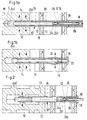
- the fastening anchor 10 has an elongated, hollow fastening body 12 with an anchor section 14 for fixing the fastening anchor 10 in one Masonry M of a wall shown in sections and a holding section 16 for fixing a component B.
- a sleeve 22 is inserted into the fastening body 12.
- the mounting body 12 runs through a slot 20 running parallel to its longitudinal axis 13, so that the mounting body 12 has a substantially C-shaped cross section having.
- the sleeve 22 lies with its flange 18 both on this and - in Installation state - on the outer surface of component B.
- the diameter of the Flange 18 in the sleeve 22 is larger than the constant over its length Diameter of the tubular but slotted fastening body 12.
- an expansion body 24 used such that he is frustoconical Section 24c and a cylindrical section 24a in direct connection to the inner end of the sleeve 22 in the holding section 16 of the fastening body 12 located.
- a smaller diameter cylindrical portion 24b projects into the sleeve 22 in. This counteracts the cylindrical section 24a of larger diameter set end of the cylindrical section 24b is via a predetermined breaking point 26 a cylindrical tie rod 28 connected, which in the provisional installation position 1 a protrudes from the fastening anchor 10.
- a blind hole S is drilled into the masonry M.
- Anchor section 14 of a fastening body previously inserted into component B. 12 of a fastening anchor 10 inserted; in the example there is the component B from the hollow profile frame of a window and the fastening anchor 10 leading through hole D may have been provided at the factory.
- the fastening body 12 is so far with its anchor portion 14 in that Blind hole S inserted that the flange 18 of the sleeve 22 on the outer surface of component B is applied.
- the Fastening body 12 because its outer diameter is slightly larger than that of Blind hole S is deformed a little elastically and lies with that of the restoring force caused friction in the blind hole S on the masonry M.
- the collection of the Fastening body 12 can be done, for example, with an auxiliary sleeve H, which engages over the rod 28 without contact and with the component B facing it End face can be applied to the flange 18 of the sleeve 22, so that then driving in with a hammer or similar tool up to that in Fig. 1 a shown state can be made.
- auxiliary sleeve H After removing the auxiliary sleeve H is a pulling tool on the rod 28 from Known blind rivets and the rod 28 from the sleeve 22 and thus pulled out the mounting body 12.
- Fig. 1b shows the widening caused thereby both the sleeve 22 and the fastening body 12. This widening of the fastening body 12 in the holding section 16 leads to a form-fitting fixation of the component B and thus its Relative position to the masonry M.
- the cylindrical section 24a of the expansion body 24 projects beyond the end of the Fastening body 12 on the anchor portion 14 and has another there frusto-conical portion 24d whose largest diameter is larger than the inner diameter of the fastening body 12.
- the anchor section 14 'of an approach made of elastic material on the fastening body 12 ' educated.
- Section 14 ' has an axial bore widening towards the free end, into which in turn a frustoconical section 24d 'of the expansion body 24 takes hold.
- Section 24d ' has a significantly smaller pitch angle than that Section 24d in Fig. 1, so that it during the expansion process by pulling on the Rod 28 expanded less and with less force on the masonry is present.
- This embodiment of the fastening anchor 10 is therefore suitable - as shown - especially for pressure-sensitive masonry, namely such porous material or the like
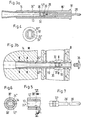
- the embodiment of the fastening anchor 10 shown in FIGS. 3a and b also uses the functional principle of blind riveting, differs but from the previously described embodiments in several respects. So is the flange 18 'part of the mounting body 12 ", which is unslotted and in a part of the holding portion 16 'following the flange 18' a larger Has wall thickness, such that in this part of section 16 'the axial Through opening of the mounting body 12 "is less than above it remaining length. This remaining length is from the other end of the mounting body 12 "ago an expansion body 24" inserted, which over the above End of the anchor section 14 protrudes.
- 5 to 7 illustrate a variant of the locking of the actuating element 32 in the sleeve-shaped expansion body 24 "in that a pair of notches 30 '(or possibly two at a distance from each other) in the sleeve-shaped expansion body 24 "leave a through opening 34 according to FIG. 6 and that 7 has a corresponding cross section, so that it is inserted from the outside through the opening 34 and by turning can be locked by 90 ° behind the notches 30 '. 7 also shows sets the rod 28 'directly and without a predetermined breaking point 26 on the actuating element 32 'on. In this way, the actuator 32 'with the Rod 28 'after the sleeve-shaped expander 24 "into that shown in Fig. 5 Was brought out of the expander 24 "after unlocking pull out and reuse; a plastic plug 36 closes the Fastening anchor 10.
Landscapes
- Engineering & Computer Science (AREA)
- General Engineering & Computer Science (AREA)
- Mechanical Engineering (AREA)
- Joining Of Building Structures In Genera (AREA)
- Dowels (AREA)
- Door And Window Frames Mounted To Openings (AREA)
- Insertion Pins And Rivets (AREA)
- Materials For Medical Uses (AREA)
- Prostheses (AREA)
Description
- Fig. 1a, b
- ein erstes Ausführungsbeispiel des erfindungsgemäßen Befestigungsankers in der vorläufigen sowie derendgültigen Einbaulage;
- Fig. 2
- ein zweites Ausführungsbeispiel des erfindungsgemäßen Befestigungsankers in der vorläufigen Einbaulage;
- Fig. 3a, b
- ein drittes Ausführungsbeispiel des erfindungsgemäßen Befestigungsankers, und zwar vor dem Einbau sowie in der endgültigen Einbaulage;
- Fig. 4
- eine Endansicht des Befestigungsankers in Fig. 3a (von links);
- Fig. 5
- einen abgebrochenen Längsschnitt durch einen ähnlichen Befestigungsanker wie in Fig. 3a (ohne Betätigungselement);
- Fig. 6
- einen Querschnitt gemäß der Linie VI-VI in Fig. 5; und
- Fig. 7
- ein zum Befestigungsanker der Fig. 5 und 6 gehörendes Betätigungselement in Seitenansicht (und eingezeichnetem Querschnitt).
Claims (7)
- Befestigungsanker zum Anbringen eines Bauelements, insbesondere eines Fensterrahmens, an einer Wand oder dgl., mit einem im wesentlichen rohrförmig zylindrischen Befestigungskörper (12), der im Bereich seines ersten Endes einen Ankerabschnitt (14) zur Verankerung in der Wand (M) und im Bereich seines zweiten Endes einen Halteabschnitt (16) zum Halten des Bauelements (B) sowie in seinem Inneren Mittel (Aufweitkörper 24) aufweist, durch deren axiale Längsverschiebung der Befestigungskörper (12) sowohl im Bereich des Halteabschnitts (16) als auch im Bereich des Ankerabschnitts (14) im wesentlichen radial aufweitbar ist, wobei die Aufweitmittel eine mit Aufweitkörpern (24) verbundene, in der Einbaulage durch ein Werkzeug beaufschlagbare Stange (28) enthalten,
dadurch gekennzeichnet, daß die Stange (28) eine Zugstange und der Befestigungskörper (12) mit den Aufweitkörpern (24) im Halteabschnitt (16) blindnietartig (Sollbruchstelle 26) ausgebildet ist. - Befestigungsanker nach Anspruch 1,
dadurch gekennzeichnet, daß im Halteabschnitt (16) zwischen dem Befestigungskörper (12) und der Stange (28) eine Hülse (22) angeordnet ist, welche die Durchmesserdifferenz zwischen dem Aufweitkörper (24) und dem Befestigungskörper (12) darstellt. - Befestigungsanker nach Anspruch 1 oder 2,
dadurch gekennzeichnet, daß die Zugstange (28) im Ausgangszustand den Ankerabschnitt (14) des Befestigungskörpers (12) überragt und einen sich kegelstumpfförmig erweiterten Abschnitt (24d) aufweist, dessen größter Durchmesser größer als der Innendurchmesser des Befestigungskörpers (12) ist. - Befestigungsanker nach Anspruch 3,
dadurch gekennzeichnet, daß der Ankerabschnitt (14') des Befestigungskörpers (12) von einem aus elastischem Material bestehenden Ansatz gebildet ist. - Befestigungsanker zum Anbringen eines Bauelements, insbesondere eines Fensterrahmens, an einer Wand oder dgl., mit einem im wesentlichen rohrförmig zylindrischen Befestigungskörper (12), der im Bereich seines ersten Endes einen Ankerabschnitt (14) zur Verankerung in der Wand (M) und im Bereich seines zweiten Endes einen Halteabschnitt (16) zum Halten des Bauelements (B) sowie in seinem Inneren Mittel (Aufweitkörper 24) aufweist, durch deren axiale Längsverschiebung der Befestigungskörper (12) sowohl im Bereich des Halteabschnitts (16) als auch im Bereich des Ankerabschnitts (14) im wesentlichen radial aufweitbar ist, wobei die Aufweitmittel eine mit Aufweitkörpern (24) verbundene, in der Einbaulage durch ein Werkzeug beaufschlagbare Stange (28) enthalten,
dadurch gekennzeichnet, daß die Stange (28) eine Zugstange und diese mit einer die Aufweitmittel bildenden Hülse (24") zu gemeinsamer Längsverschiebung verriegelt ist. - Befestigungsanker nach Anspruch 5,
dadurch gekennzeichnet, daß die Verriegelung (Kerben 30') lösbar und die Stange (28') aus der Hülse (24") herausziehbar ist. - Befestigungsanker nach Anspruch 5 oder 6,
dadurch gekennzeichnet, daß der der Zugstange (28, 28') gegenüberliegende, im Ausgangszustand den Befestigungskörper (12") überragende Endbereich des hülsenförmigen Aufweitkörpers (24") zur Ovalform abgeplattet ist, wobei die lange Ovalachse größer ist als der Innendurchmesser des Befestigungskörpers (12").
Applications Claiming Priority (2)
| Application Number | Priority Date | Filing Date | Title |
|---|---|---|---|
| DE29509726U | 1995-06-14 | ||
| DE29509726U DE29509726U1 (de) | 1995-06-14 | 1995-06-14 | Nietanker |
Publications (2)
| Publication Number | Publication Date |
|---|---|
| EP0748943A1 EP0748943A1 (de) | 1996-12-18 |
| EP0748943B1 true EP0748943B1 (de) | 2000-04-19 |
Family
ID=8009320
Family Applications (1)
| Application Number | Title | Priority Date | Filing Date |
|---|---|---|---|
| EP96109292A Expired - Lifetime EP0748943B1 (de) | 1995-06-14 | 1996-06-11 | Befestigungsanker |
Country Status (6)
| Country | Link |
|---|---|
| EP (1) | EP0748943B1 (de) |
| AT (1) | ATE191960T1 (de) |
| CZ (1) | CZ165796A3 (de) |
| DE (2) | DE29509726U1 (de) |
| HU (1) | HUP9601530A3 (de) |
| PL (1) | PL314747A1 (de) |
Cited By (2)
| Publication number | Priority date | Publication date | Assignee | Title |
|---|---|---|---|---|
| DE20109979U1 (de) * | 2001-06-16 | 2002-10-17 | EJOT Verbindungstechnik GmbH & Co. KG, 57334 Bad Laasphe | Befestigungsanker mit Hülse und Aufweitkörper |
| DE102009005456A1 (de) * | 2009-01-21 | 2010-07-29 | Josef Gartner Gmbh | Befestigungsanker und Verfahren zum Befestigen einer Fassade |
Families Citing this family (3)
| Publication number | Priority date | Publication date | Assignee | Title |
|---|---|---|---|---|
| DE102009043650A1 (de) * | 2009-09-29 | 2011-03-31 | Fischerwerke Gmbh & Co. Kg | Doppel-Dübel für eine Abstandsmontage |
| PE20221708A1 (es) * | 2019-11-20 | 2022-11-02 | Metso Outotec Finland Oy | Tornillo sin tuerca |
| DE102022108167A1 (de) * | 2022-04-05 | 2023-10-05 | Lisi Automotive Kkp Gmbh & Co. Kg | Spreizniet |
Family Cites Families (5)
| Publication number | Priority date | Publication date | Assignee | Title |
|---|---|---|---|---|
| GB594859A (en) * | 1945-07-03 | 1947-11-20 | British United Shoe Machinery | Improvements in or relating to riveting |
| DE3023345C2 (de) * | 1980-06-21 | 1982-10-28 | Upat Gmbh & Co, 7830 Emmendingen | Isolierplatten-Dübel |
| DE3105036A1 (de) * | 1981-01-29 | 1982-09-09 | Günter 5013 Elsdorf Busch | Duebel fuer die befestigung von rahmen |
| DE3109275A1 (de) * | 1981-03-11 | 1982-09-30 | Hilti AG, 9494 Schaan | Spreizduebel |
| GB8615351D0 (en) * | 1986-06-24 | 1986-07-30 | Tackburn Ltd | Fixing device |
-
1995
- 1995-06-14 DE DE29509726U patent/DE29509726U1/de not_active Expired - Lifetime
-
1996
- 1996-06-05 HU HU9601530A patent/HUP9601530A3/hu unknown
- 1996-06-06 CZ CZ961657A patent/CZ165796A3/cs unknown
- 1996-06-11 AT AT96109292T patent/ATE191960T1/de not_active IP Right Cessation
- 1996-06-11 DE DE59604987T patent/DE59604987D1/de not_active Expired - Fee Related
- 1996-06-11 EP EP96109292A patent/EP0748943B1/de not_active Expired - Lifetime
- 1996-06-12 PL PL96314747A patent/PL314747A1/xx unknown
Cited By (3)
| Publication number | Priority date | Publication date | Assignee | Title |
|---|---|---|---|---|
| DE20109979U1 (de) * | 2001-06-16 | 2002-10-17 | EJOT Verbindungstechnik GmbH & Co. KG, 57334 Bad Laasphe | Befestigungsanker mit Hülse und Aufweitkörper |
| DE102009005456A1 (de) * | 2009-01-21 | 2010-07-29 | Josef Gartner Gmbh | Befestigungsanker und Verfahren zum Befestigen einer Fassade |
| DE102009005456B4 (de) * | 2009-01-21 | 2011-02-24 | Josef Gartner Gmbh | Befestigungsanker zum Befestigen einer Fassade an einem Gebäude |
Also Published As
| Publication number | Publication date |
|---|---|
| DE29509726U1 (de) | 1996-10-17 |
| DE59604987D1 (de) | 2000-05-25 |
| PL314747A1 (en) | 1996-12-23 |
| CZ165796A3 (en) | 1997-01-15 |
| HUP9601530A3 (en) | 1998-12-28 |
| HUP9601530A2 (hu) | 1998-07-28 |
| ATE191960T1 (de) | 2000-05-15 |
| HU9601530D0 (en) | 1996-08-28 |
| EP0748943A1 (de) | 1996-12-18 |
Similar Documents
| Publication | Publication Date | Title |
|---|---|---|
| DE602005000797T2 (de) | Element zum Befestigen von Zubehörteilen an Metallfenstern und Metalltüren | |
| DE69923962T2 (de) | Knochenimplantat mit einer reversiblen befestigungsvorrichtung | |
| DE69211248T2 (de) | Hochleistungs-Blindboltzen mit gleicher Greifkraft über einen erweiterten Greifbereich | |
| EP0574669B1 (de) | Spreizanker | |
| DE102006047391B4 (de) | Verbesserungen bei Verbindungserzeugungsvorrichtungen | |
| DE2940514C2 (de) | ||
| DE3124685A1 (de) | Spreizduebel fuer die verankerung in konisch nach innen erweitert hergestellten bohrloechern | |
| DE3523155C2 (de) | ||
| DE1927065B2 (de) | Anordnung zum anbringen eines befestigungselementes in wenigstens einem werkstueck | |
| DE4210488A1 (de) | Verbindungseinrichtung für ein insbesondere rohrförmiges Bauteil | |
| EP0060973B1 (de) | Spreizdübel für die Verankerung in konisch nach innen erweitert hergestellten Bohrlöchern | |
| DE19607029C1 (de) | Vorrichtung zur Befestigung eines Beschlages in einer Zarge | |
| EP0728882B1 (de) | Befestigungselement zum Befestigen von Platten grosser Dicke an Bauteilen | |
| EP0748943A1 (de) | Befestigungsanker | |
| CH642723A5 (en) | Expanding dowel for attaching cladding elements with a gap | |
| DE2656958A1 (de) | Eckverbindung von auf gehrung geschnittenen profilen | |
| DE4213862C2 (de) | Blindnietartiger Klemmverbinder | |
| EP0425794B1 (de) | Scharniergelenk, insbesondere für Fenster, Türen od. dgl. | |
| DE19923107C1 (de) | Befestigungsvorrichtung zur Befestigung eines Möbelteils an einem Bauteil oder einem weiteren Möbelteil | |
| DD244787A5 (de) | Duebel | |
| EP0558890B1 (de) | Spreizdübel | |
| EP3536987B1 (de) | System und verfahren zur befestigung eines dämmstoffs | |
| CH660404A5 (de) | Spreizduebel. | |
| DE2419462C3 (de) | Vorrichtung zum Verbinden eines Abdeckrahmens mit einem Tragrahmen von Türen oder Fenstern | |
| EP1114905A1 (de) | Montagehülse |
Legal Events
| Date | Code | Title | Description |
|---|---|---|---|
| PUAI | Public reference made under article 153(3) epc to a published international application that has entered the european phase |
Free format text: ORIGINAL CODE: 0009012 |
|
| AK | Designated contracting states |
Kind code of ref document: A1 Designated state(s): AT CH DE FR GB LI |
|
| 17P | Request for examination filed |
Effective date: 19970507 |
|
| 17Q | First examination report despatched |
Effective date: 19990318 |
|
| GRAG | Despatch of communication of intention to grant |
Free format text: ORIGINAL CODE: EPIDOS AGRA |
|
| GRAG | Despatch of communication of intention to grant |
Free format text: ORIGINAL CODE: EPIDOS AGRA |
|
| GRAH | Despatch of communication of intention to grant a patent |
Free format text: ORIGINAL CODE: EPIDOS IGRA |
|
| GRAH | Despatch of communication of intention to grant a patent |
Free format text: ORIGINAL CODE: EPIDOS IGRA |
|
| GRAA | (expected) grant |
Free format text: ORIGINAL CODE: 0009210 |
|
| AK | Designated contracting states |
Kind code of ref document: B1 Designated state(s): AT CH DE FR GB LI |
|
| REF | Corresponds to: |
Ref document number: 191960 Country of ref document: AT Date of ref document: 20000515 Kind code of ref document: T |
|
| REG | Reference to a national code |
Ref country code: CH Ref legal event code: EP |
|
| GBT | Gb: translation of ep patent filed (gb section 77(6)(a)/1977) |
Effective date: 20000419 |
|
| REF | Corresponds to: |
Ref document number: 59604987 Country of ref document: DE Date of ref document: 20000525 |
|
| ET | Fr: translation filed | ||
| PG25 | Lapsed in a contracting state [announced via postgrant information from national office to epo] |
Ref country code: AT Free format text: LAPSE BECAUSE OF NON-PAYMENT OF DUE FEES Effective date: 20000611 |
|
| PG25 | Lapsed in a contracting state [announced via postgrant information from national office to epo] |
Ref country code: LI Free format text: LAPSE BECAUSE OF NON-PAYMENT OF DUE FEES Effective date: 20000630 Ref country code: CH Free format text: LAPSE BECAUSE OF NON-PAYMENT OF DUE FEES Effective date: 20000630 |
|
| REG | Reference to a national code |
Ref country code: CH Ref legal event code: PL |
|
| PLBE | No opposition filed within time limit |
Free format text: ORIGINAL CODE: 0009261 |
|
| STAA | Information on the status of an ep patent application or granted ep patent |
Free format text: STATUS: NO OPPOSITION FILED WITHIN TIME LIMIT |
|
| 26N | No opposition filed | ||
| REG | Reference to a national code |
Ref country code: GB Ref legal event code: IF02 |
|
| PGFP | Annual fee paid to national office [announced via postgrant information from national office to epo] |
Ref country code: GB Payment date: 20050603 Year of fee payment: 10 |
|
| PGFP | Annual fee paid to national office [announced via postgrant information from national office to epo] |
Ref country code: FR Payment date: 20050621 Year of fee payment: 10 |
|
| PGFP | Annual fee paid to national office [announced via postgrant information from national office to epo] |
Ref country code: DE Payment date: 20050706 Year of fee payment: 10 |
|
| PG25 | Lapsed in a contracting state [announced via postgrant information from national office to epo] |
Ref country code: GB Free format text: LAPSE BECAUSE OF NON-PAYMENT OF DUE FEES Effective date: 20060611 |
|
| PG25 | Lapsed in a contracting state [announced via postgrant information from national office to epo] |
Ref country code: DE Free format text: LAPSE BECAUSE OF NON-PAYMENT OF DUE FEES Effective date: 20070103 |
|
| GBPC | Gb: european patent ceased through non-payment of renewal fee |
Effective date: 20060611 |
|
| REG | Reference to a national code |
Ref country code: FR Ref legal event code: ST Effective date: 20070228 |
|
| PG25 | Lapsed in a contracting state [announced via postgrant information from national office to epo] |
Ref country code: FR Free format text: LAPSE BECAUSE OF NON-PAYMENT OF DUE FEES Effective date: 20060630 |