EP0748612A2 - Surgical suturing apparatus - Google Patents
Surgical suturing apparatus Download PDFInfo
- Publication number
- EP0748612A2 EP0748612A2 EP96106187A EP96106187A EP0748612A2 EP 0748612 A2 EP0748612 A2 EP 0748612A2 EP 96106187 A EP96106187 A EP 96106187A EP 96106187 A EP96106187 A EP 96106187A EP 0748612 A2 EP0748612 A2 EP 0748612A2
- Authority
- EP
- European Patent Office
- Prior art keywords
- jaws
- needles
- body tissue
- suture
- actuator
- Prior art date
- Legal status (The legal status is an assumption and is not a legal conclusion. Google has not performed a legal analysis and makes no representation as to the accuracy of the status listed.)
- Granted
Links
Images


Classifications
-
- A—HUMAN NECESSITIES
- A61—MEDICAL OR VETERINARY SCIENCE; HYGIENE
- A61B—DIAGNOSIS; SURGERY; IDENTIFICATION
- A61B17/00—Surgical instruments, devices or methods, e.g. tourniquets
- A61B17/04—Surgical instruments, devices or methods, e.g. tourniquets for suturing wounds; Holders or packages for needles or suture materials
- A61B17/0469—Suturing instruments for use in minimally invasive surgery, e.g. endoscopic surgery
-
- A—HUMAN NECESSITIES
- A61—MEDICAL OR VETERINARY SCIENCE; HYGIENE
- A61B—DIAGNOSIS; SURGERY; IDENTIFICATION
- A61B17/00—Surgical instruments, devices or methods, e.g. tourniquets
- A61B17/04—Surgical instruments, devices or methods, e.g. tourniquets for suturing wounds; Holders or packages for needles or suture materials
- A61B17/0482—Needle or suture guides
-
- A—HUMAN NECESSITIES
- A61—MEDICAL OR VETERINARY SCIENCE; HYGIENE
- A61B—DIAGNOSIS; SURGERY; IDENTIFICATION
- A61B17/00—Surgical instruments, devices or methods, e.g. tourniquets
- A61B17/0057—Implements for plugging an opening in the wall of a hollow or tubular organ, e.g. for sealing a vessel puncture or closing a cardiac septal defect
- A61B2017/00637—Implements for plugging an opening in the wall of a hollow or tubular organ, e.g. for sealing a vessel puncture or closing a cardiac septal defect for sealing trocar wounds through abdominal wall
-
- A—HUMAN NECESSITIES
- A61—MEDICAL OR VETERINARY SCIENCE; HYGIENE
- A61B—DIAGNOSIS; SURGERY; IDENTIFICATION
- A61B17/00—Surgical instruments, devices or methods, e.g. tourniquets
- A61B17/04—Surgical instruments, devices or methods, e.g. tourniquets for suturing wounds; Holders or packages for needles or suture materials
- A61B17/0469—Suturing instruments for use in minimally invasive surgery, e.g. endoscopic surgery
- A61B2017/047—Suturing instruments for use in minimally invasive surgery, e.g. endoscopic surgery having at least one proximally pointing needle located at the distal end of the instrument, e.g. for suturing trocar puncture wounds starting from inside the body
-
- A—HUMAN NECESSITIES
- A61—MEDICAL OR VETERINARY SCIENCE; HYGIENE
- A61B—DIAGNOSIS; SURGERY; IDENTIFICATION
- A61B17/00—Surgical instruments, devices or methods, e.g. tourniquets
- A61B17/04—Surgical instruments, devices or methods, e.g. tourniquets for suturing wounds; Holders or packages for needles or suture materials
- A61B17/0469—Suturing instruments for use in minimally invasive surgery, e.g. endoscopic surgery
- A61B2017/0472—Multiple-needled, e.g. double-needled, instruments
-
- A—HUMAN NECESSITIES
- A61—MEDICAL OR VETERINARY SCIENCE; HYGIENE
- A61B—DIAGNOSIS; SURGERY; IDENTIFICATION
- A61B17/00—Surgical instruments, devices or methods, e.g. tourniquets
- A61B17/04—Surgical instruments, devices or methods, e.g. tourniquets for suturing wounds; Holders or packages for needles or suture materials
- A61B17/06—Needles ; Sutures; Needle-suture combinations; Holders or packages for needles or suture materials
- A61B2017/06057—Double-armed sutures, i.e. sutures having a needle attached to each end
-
- A—HUMAN NECESSITIES
- A61—MEDICAL OR VETERINARY SCIENCE; HYGIENE
- A61B—DIAGNOSIS; SURGERY; IDENTIFICATION
- A61B17/00—Surgical instruments, devices or methods, e.g. tourniquets
- A61B17/28—Surgical forceps
- A61B17/29—Forceps for use in minimally invasive surgery
- A61B2017/2926—Details of heads or jaws
Definitions
- This application relates to a surgical apparatus for suturing body tissue, and more particularly to an endoscopic apparatus for closing an incision created by a trocar.
- Endoscopic and laparoscopic surgical procedures are performed through access ports or through small incisions in the body tissue.
- a plurality of trocars comprising an obturator with a sharp penetrating tip and a hollow cannula are inserted through the skin and underlying tissue layers into the body cavity.
- the obturator is then removed, leaving the cannula positioned in the body to provide an access port to the surgical site for introduction of a variety of surgical instruments such as staplers, clip appliers, scissors, retractors and graspers to perform the surgical procedure.
- the cannulas are withdrawn from the body tissue leaving an opening usually ranging from 5 to 20 millimeters, depending on the size of the cannula being used.
- these trocar incisions are closed by the surgeon manually suturing the wound edges.
- suturing does not always effectively close the lowermost layers of tissue, e.g., the muscle and fascia layers, thereby providing sub-standard wound closure.
- U.S. Patent No. 5,368,601 to Sauer This instrument contains two needles which are deployed inside the body cavity with the pointed tips facing upwardly towards the skin.
- U.S. Patent No. 5,320,632 to Heidmueller discloses a wound closure instrument having a pair of needles pointed upwardly and a slidable needle shield to capture the needle tips when pulled upwardly through the skin.
- Another type of wound closure device is disclosed in U.S. Patent No. 5,364,482 to Gordon. In Gordon, a pair of curved needles are deployed from the apparatus in an arcuate path to penetrate the lowermost layers of the wound.
- An apparatus for suturing body tissue comprising an elongated body portion, first and second jaws pivotably mounted to the distal portion of the body portion, and first and second needles movable with respect to the first and second jaws, respectively.
- a first actuator is operatively associated with the first and second jaws for moving the jaws from a first to a second position and a second actuator is operatively associated with the first and second needles for advancing the needles through the body tissue.
- each of the jaws has a recess for receiving body tissue and a needle receiving member (a ferrule) mounted therein such that actuation of the second actuator advances the first and second needles into engagement with one of the ferrules.
- a suture is connected at each end to one of the ferrules such that advancement of the needles to engage the ferrules effectively connects the needles to the suture and retraction of the needles after such engagement pulls the ferrules and suture through the body tissue.
- the first actuator is longitudinally slidable and is operatively connected to an elongated plunger which is slid distally to cam the first and second jaws to the open position.
- the second actuator is also preferably longitudinally slidable and is operatively connected to first and second needle drivers (elongated rods) which are connected to first and second flexible mounting rods.
- the first and second flexible rods mount the first and second needles and are preferably composed of a superelastic material which enables movement at an acute angle with respect to the longitudinal axis of the elongated housing when the jaws are moved to their open position.
- the apparatus preferably also includes a safety latch which prevents actuation of the second actuator if the jaws are not in the open position.
- the safety latch has a step portion engageable with a portion of the needle driving mechanism to block movement thereof if the jaw actuation mechanism has not been actuated to move the jaws to the open position. Sliding movement of the jaw actuation mechanism to open the jaws automatically cams the safety latch out of the blocking position to allow subsequent movement of the needle driving mechanism.
- a method for closing a trocar wound comprising the steps of inserting an apparatus having first and second jaws and first and second needles into the body cavity through the trocar wound, spreading the first and second jaws to an open position, and advancing the first needle through the first jaw and the second needle through the second jaw to penetrate body tissue.
- the step of advancing the first and second needles includes the step of advancing the needles in a distal direction at an angle to the longitudinal axis to connect each needle to an end portion of a suture positioned in a distal end of the jaws.
- the step of connecting each needle to the suture includes the step of each needle frictionally engaging a ferrule connected to each end of the suture.
- the method for closing the trocar wound further includes the step of retracting the needles after engagement with the ferrules, moving the jaws to the closed position, and withdrawing the apparatus from the body cavity to pull the suture through the tissue.
- the suture is then removed from the ferrules and a knot is formed in the suture outside the body cavity and the knot is secured at the level of the muscle in the trocar wound.
- a method is also disclosed in which prior to tying a knot in the suture after the suture has been pulled through the body tissue, the suture is wrapped around a cannula fastening device to help retain the trocar cannula in position with respect to the body tissue during the surgical procedure. At the end of the surgical procedure, the suture is unwound from the cannula fastening device and tied outside the body cavity to close the trocar incision.
- a surgical apparatus designated generally by reference numeral 10, is provided for closing incisions in body tissue.
- the trocar typically includes an obturator having a piercing tip and a hollow cannula. After insertion, the obturator is removed, leaving the cannula in place to provide an access port for endoscopic instruments such as staplers, clip appliers, graspers, scissors and other instruments necessary to perform the surgical procedure.
- endoscopic instruments such as staplers, clip appliers, graspers, scissors and other instruments necessary to perform the surgical procedure.
- the instruments may be inserted directly through the body tissue to access the surgical site without the use of a cannula. In either case, at the end of the surgical procedure, an incision remains through the underlying tissue layers, created by the trocar or by the direct insertion of the instruments, which the apparatus 10 disclosed herein is designed to close.
- the apparatus 10 has an elongated body portion or shaft 12 which is dimensioned for insertion through either a trocar cannula or directly into a small incision in the body tissue.
- a jaw actuation mechanism which includes actuator 26, is slid forward (distally) to spread the jaws 14, 16 from the closed position of Fig. 1 to an open position.
- a needle driving mechanism which includes end cap 100, is pressed distally to advance a pair of surgical needles through the body tissue and into the distal end of the jaws.
- the needles each engage a ferrule connected at opposite ends to a suture and positioned in the distal end of the jaws.
- the needles when the needles are retracted to their initial position, they carry their associated ferrules and connected suture through the body tissue to place the suture on both sides of the trocar incision.
- the suture is then tensioned and manually tied from outside the body to approximate the tissue on both sides of the trocar incision and to close the incision.
- the housing portion of apparatus 10 includes a cap housing 30 which is mounted within a grip portion 34.
- a pair of wings 36 extend radially from grip portion 34 to facilitate grasping by the user.
- a bushing 38 configured for supporting elongated body portion 12, is seated within a central bore 33 of grip portion 34.
- a detent washer 39 is positioned at a distal end of cap housing 30, in abutment with wall 30a, and is configured to facilitate retention of the rear plunger of the jaw actuation mechanism described below.
- a suture receiving channel 31 (see Figs. 3B and 6) is formed in both body halves for ease of manufacture, although suture 20 is positioned, as shown, in only one suture receiving channel 31.
- Proximal and distal detents 40a, 42a are formed in body half 12a and proximal and distal detents 40b and 42b are formed in body half 12b (see Figs. 7 and 3) for the reasons described below.
- the jaw actuation mechanism is movable between a retracted (proximalmost) position in which the jaws 14, 16 are maintained in the closed position and an advanced (distalmost) position in which the jaws 14, 16 are spread to an open position.
- the jaw actuating mechanism includes an actuator 26 in the form of a thumb pad, a rear plunger 50, a front plunger 54 and a plunger latch 70, all of which are movable between retracted and advanced positions.
- Plunger return spring 68 is mounted over rear plunger 50 and sandwiched between plunger latch 70 and detent washer 39 to bias the plunger latch 70 (and rear plunger 50) proximally to its retracted position.
- Rear plunger 50 has a radially extending flange 52 at a proximal end for mounting thumb pad 26, and a distally extending flattened tongue 56 having an opening 58 to receive a drive pin 60.
- Front plunger 54 as shown in Fig. 3A, has an elongated slot 64 formed at a proximal end to accommodate drive pin 60.
- a pair of projections 66a, 66b (Fig. 3), formed on arms 65, engage either the detents 40a, 40b or 42a, 42b in the shaft 12, depending on the longitudinal position of the plunger 54. That is, in the initial position of the plunger 54, projections 66a, 66b engage proximal detents 40a, 40b of body halves 12a, 12b to help maintain the jaws 14, 16 in the closed position.
- projections 66a, 66b engage distal detents 42a and 42b to help maintain the jaws in the open position and provide a tactile feel to the user to indicate deployment of the jaws to the open position.
- plunger latch 70 has a pair of longitudinally extending arms 72 terminating in retention tips 73 and a central aperture 74 dimensioned for reception of rear plunger 50.
- Mounting pin 75 extends through aperture 51 in rear plunger 50 and top and bottom openings of plunger latch 70 to connect plunger latch 70 to rear plunger 50.
- the plunger latch 70 which advances and retracts along with movement of the plungers 50, 54, functions to both lock the jaw actuating mechanism in the advanced position and to disengage the safety mechanism of the apparatus. This is described in detail below.
- the jaws can be provided with cam slots to receive a camming pin positioned on an actuating rod and a trigger or a pivotable handle mechanism instead of a slidable thumb pad could be utilized.
- the jaws can alternately be normally biased in the open position such that actuation of the jaw actuation mechanism will close the jaws.
- the needle driving mechanism is movable between a retracted (proximalmost) position wherein the needles 18, 19 are shielded within the jaws 14, 16 and an advanced (distalmost) position wherein the needles 18, 19 are advanced to penetrate body tissue.
- the needle driving mechanism includes an end cap 100, a driver stop 102, a pair of needle drivers 104a, 104b and a pair of mounting wires 106a, 106b for frictionally mounting needles 18, 19, respectively.
- a compression spring 108 sandwiched between detent washer 39 and driver stop 102, biases driver stop 102 (and end cap 100) proximally to its retracted position.
- End cap 100 is slidably mounted with respect to cap housing 30 and has an axial bore 112 for receiving rear plunger 50, a groove 110 to accommodate flange 52 of rear plunger 50, and channels 111a, 111b to accommodate assembly latch 37 and safety latch 80 (described below) when the end cap 100 is slid distally within central bore 32 of cap housing 30.
- end cap 100 During advancement of thumb pad 26 to advance rear plunger 50 to open the jaws 14, 16, end cap 100 remains stationary as flange 52 slides within groove 110.
- Driver stop 102 of the needle driving mechanism is seated within a proximal end of central bore 32 of cap housing 30, and has a proximal flange 116 which is frictionally mounted within axial bore 112 of end cap 100.
- a pair of legs 114 each having an indentation 120, extend distally from driver stop 102 and interact with arms 72 and retention tips 73 of plunger latch 70 in a manner described below.
- Top and bottom grooves 118, 119 are dimensioned to receive assembly latch 37 and safety latch 80 therethrough to allow unimpeded movement of driver stop 102.
- Top and bottom projections 107a, 107b are seated within channels 30b formed along the length of the inner surface of cap housing 30, as best seen in Fig. 4.
- Central opening 103 accommodates rear plunger 50.
- Needle drivers in the form of elongated drive rods 104a, 104b are each mounted to driver stop 102 for movement therewith via proximal mounting flanges 120a and 120b which are snapped over the inner wall of driver stop 102 (see Figs. 1A and 3).
- the distal forked ends 116a, 116b of needle drivers 104a, 104b frictionally engage mounting wires 106a, 106b, respectively.
- the needles 18, 19, are in turn frictionally mounted within a recess formed in wires 106a, 106b, respectively.
- the needles can have a recess formed therein for frictionally mounting to the wires 106a, 106b.
- the mounting wires are preferably made of superelastic wire, such as Tinel or Nitinol wire, to allow flexing and bending to enable the needles to travel through the jaws 14, 16 when the jaws are positioned in their angular open position.
- superelastic wire such as Tinel or Nitinol wire
- Clearly other materials can also be utilized to enable the mounting wires to perform their function.
- Figures 2 and 3 show the needle driving mechanism in the proximalmost position wherein head 101 of end cap 100 is spaced from cap housing 30, driver stop 102 is positioned within a proximal portion of cap housing 30, and needle drivers 104a, 104b and their respective mounting wires 106a, 106b and needles 18 and 19 are also in the retracted position.
- Figure 9 illustrates the needle driving mechanism in the deployed position to advance the surgical needles 18, 19.
- driver stop 102 and connected needle drivers 104a, 104b are also forced distally. This movement of the needle driving mechanism is described in more detail below.
- Assembly latch 37 (Figs. 1A and 3) has a leg 37b which extends through top groove 118 of driver stop 102 as shown in Fig. 3. Opposing leg 37a is fixed within annular channel 30b of cap housing 30, thereby functioning to connect driver stop 102 to the cap housing 30. Leg 37b enters channel llla of end cap 100 when end cap 100 is slid distally.
- jaws 14, 16 of the surgical apparatus 10 are pivotably mounted to body portion 12 via pivot pin 132 extending through apertures 130.
- a tissue gap or recess portion 142 and 143 is formed in each jaw 14, 16 respectively, for receiving body tissue to be sutured.
- Angled proximal edges 146, 148 are configured so that engagement by abutment surface 62 of front plunger 54 cams the jaws to the open position of Fig. 7A. As shown, the jaws rotate about pin 132 in opposite directions.
- a needle guide 133 with an exit opening 137 for the surgical needle 18 is formed proximal of recess portion 142 of jaw 14. Distal of recess portion 142 is an entrance opening 144, and a cutout for receiving oval shaped ferrule 24.
- a suture guide or groove 131 is formed in jaw 14 to accommodate suture 20.
- Jaw 16 is a mirror image of jaw 14, and as shown in Fig. 3B has a needle guide 136, an exit opening 138, an entrance opening 141, a cutout for receiving oval shaped ferrule 22 and a suture guide 134.
- Blunt ends 94, 95 of jaw 14, 16 are atraumatic and minimize trauma to body tissue during insertion and manipulation of the apparatus 10 in the body cavity.
- jaws 14 and 16 are positioned at an angle to the longitudinal axis of the elongated body portion 12.
- the angle is an acute angle of approximately 30° as shown, however, clearly it is contemplated to deploy the jaws to various angles with respect to the longitudinal axis of the body portion.
- needle 19 is seated within needle guide 136 and needle 18 is seated within needle guide 133 such that pointed tips 123, 125 are unexposed and not in contact with tissue.
- needle mounting wires 106a, 106b are substantially straight.
- the mounting wires 106a, 106b bend at regions 106c, 106d, respectively. Consequently, when the jaws 14 and 16 are spread to their angular position with respect to shaft 12, mounting wires 106a, 106b bend at a similar angle.
- Suture 20 is attached at one end to ferrule 22, wraps through the suture guide 134 in jaw 16, extends through central aperture 132a in pivot pin 132 and through suture guide 31 in body half 12a of shaft 12.
- the suture 20 is looped at the proximal end of suture guide 31 and extends back along the length of suture guide 31, back through central aperture 132a in pivot pin 132, around the suture guide 131 in jaw 14 and is attached at its other end to ferrule 24.
- the suture guide can extend through an opening in the cap housing 30 so that it can be manually tugged to ensure that the ferrules 22, 24 are properly seated in their respective cutouts, the suture is snugly fit into suture guides 131, 134 and the remaining length of suture lies properly in suture guide 31. Extension of the suture through the cap housing also easily accommodates extra length of suture.
- the apparatus 10 also includes a safety mechanism which prevents deployment of the needles 18, 19 if the jaws 14, 16 have not first been moved to the open position.
- the safety mechanism includes a safety latch 80 in the form of a spring which is normally in the position illustrated in Fig 3.
- Leg 84 is fixed within annular channel 30b of cap housing 30.
- Step 82 is positioned at the proximal end of latch 80 and in the initial position abuts wall 102b of driver stop 102. In this initial blocking position of Fig. 3, if the user attempts to press end cap 100 distally to advance the needles, wall 102b of driver stop 102 will contact step 82 of safety latch 80 and be blocked from distal movement.
- Safety latch 80 is automatically moved from a blocking to a non-blocking position upon advancement of the jaw actuating mechanism. More specifically, when plunger 50 is advanced to move the jaws to the open position, as shown in Fig. 7, the base portion 71 of plunger latch 70 contacts ramp surface 83 of safety latch 80 and forces it downwardly such that step 82 is cammed out of engagement with the wall 102b of driver stop 102. In this non-blocking position of Fig. 7, step 82 is aligned with groove 119 of driver stop 102 and allows for free movement thereof. Consequently, when end cap 100 is pressed inwardly to deploy the needles, driver stop 102 can likewise travel distally as groove 119 passes over step 82. Thus, driver stop 102 and the associated components of the needle driving mechanism can be advanced to the position of Fig. 9 to deploy the needles.
- end cap 100, driver stop 102, needle drivers 104a, 104b, and needle mounting wires 106a, 106b are in the proximalmost position and are prevented from movement due to the abutment of wall 102b of driver stop 102 and step 82 of safety latch 80.
- thumb pad 26 is slid distally thereby forcing rear plunger 50, plunger latch 70 and front plunger 54 distally to the advanced (distalmost) position of Figs. 7 and 7A, compressing spring 68.
- wall 71 contacts the ramp 83 of safety latch 80 to cam step 82 out of engagement with driver stop 102 in the manner described above. This frees the needle driving mechanism for advancement.
- plunger 54 is advanced, its abutment surface 62 contacts angled edges 146, 148 of jaws 14, 16 and cams the jaws in opposite directions to the open position of Fig. 7A.
- end cap 100 When the apparatus is in the desired position with the body tissue seated in the recessed portions 142, 143 of opened jaws 14, 16, end cap 100 is pressed inwardly (distally) into cap housing 30, as shown in Fig. 9, thereby forcing driver stop 102, and the needle drivers 104a, 104b connected thereto distally and compressing spring 108.
- driver stop 102 Movement of driver stop 102 is unimpeded by safety latch 80 because groove 119 is aligned with step 82.
- Channels llla, lllb of end cap 100 and grooves 118, 119 of driver stop 102 accommodate assembly latch 37 and safety latch 80 to allow free travel of end cap 100 and driver stop 102.
- Top and bottom projections 107a, 107b of driver stop 102 travel along annular channel 30b of cap housing 30.
- Advancement of needle drivers 104a, 104b advances mounting wires 106a, 106b and mounted needles 18, 19.
- Mounting wires 106a, 106b follow the acute angle of the jaws and force the needles 18, 19 through the body tissue positioned in the recess portions 142, 143 and into the entrance openings 144, 141 of jaws 14, 16 to frictionally engage the ferrules 24, 22. (see Figs. 9A and 11) Consequently, needles 18 and 19 become connected to the suture 20.
- driver stop 102 advances distally, it contacts the distal ends of arms 72 of plunger latch 70 to cam retention tips 73 out of engagement with inner wall 39a of detent washer 39 to thereby release plunger latch 70 to allow subsequent retraction.
- driver stop 102 reaches its distalmost position, as shown in Fig. 8B, the projections of arms 72 of plunger latch 70 become re-nested in the indentations 120 of legs 114 of driver stop 102.
- end cap 100 After the needles 18, 19 have been deployed into engagement with ferrules 24, 22, to retract the needles 18, 19 to pull the suture 20 through the body tissue seated into the recess portions of the jaw 14, 16 and to close the jaws to remove the instrument, end cap 100 is released and compression spring 108 forces it proximally to its initial position. As the end cap 100, driver stop 102 and associated needle drivers 104a, 104b and mounting wires 106a, 106b are retracted to pull the needles 18, 19 and ferrules 24, 22 into the exit openings 137, 138 of the jaws 14, 16, the plunger latch 70 and connected rear plunger 50 are also retracted due to the nesting of plunger latch 70 and driver stop 102 and the biasing force of compression spring 68.
- Figures 14-21 illustrate the use of the surgical suturing apparatus 10 for closing an incision created by a trocar during an endoscopic/laparoscopic procedure.
- one or more trocars are inserted through the body tissue to access the body cavity.
- a typical trocar includes an obturator having a sharp penetrating tip removably mounted within a cannula. After insertion of the trocar into the body cavity, the obturator is removed leaving the cannula in place to provide an access port for the insertion of various surgical instruments for performing the endoscopic/laproscopic surgical procedure.
- Figure 14 illustrates the trocar cannula 200 positioned in the body tissue and the apparatus 10 prior to insertion therethrough.
- the surgical apparatus 10 When it is desired to close the incision created by the trocar, the surgical apparatus 10 is inserted through the trocar cannula 200 as illustrated in Fig. 15.
- thumb pad 26 of the jaw actuation mechanism is slid distally as shown in Fig. 16 to advance the front plunger in the manner described above to spread the jaws 14, 16 to the open position.
- Both the trocar cannula 200 and the apparatus 10 are then pulled proximally in the direction of arrow A of Fig. 17 until the body tissue is seated within recess portions 142, 143 of jaws 14 and 16.
- End cap 100 of the needle driving mechanism is then slid distally to advance the needle drivers in the manner described above to advance needles 18 and 19 through the body tissue to engage the ferrules in jaws 14 and 16.
- end cap 100 is released to retract needles 18 and 19 and connected ferrules into the needle guides in the jaws 14 and 16 and allowing the jaw actuation mechanism to retract to pivot the jaws back to their initial closed position.
- the needles 18, 19 are retracted, they pull the ferrules and suture 20 through the body tissue seated in the recessed portions in the manner described above.
- the instrument 10 and trocar cannula 200 are then withdrawn together from the body tissue leaving a loop of suture adjacent the innermost tissue layer, e.g. the abdominal fascia, and the suture on both sides of the wound (extending through the fascia and muscle) as shown in Fig. 19.
- Suture 20 is cut at both ends or pulled (tugged) to separate it from the ferrules (Fig. 20), with the ferrules preferably releasing from the needles before the suture pulls out of the ferrules.
- Suture 20 is then tensioned to approximate the wound edges and a knot is tied to close the incision as shown in Fig. 21. Consequently, the incision is closed without penetrating the skin layer. Staples and/or separate suture can be manually placed through the skin and closed in the normal fashion.
- the jaws may optionally be provided with a shield to maintain pneumoperitoneum and minimize the amount of effluent from the trocar wound when the jaws are retracted to their original position.
- the shield provides continuity of the apparatus seal to the abdominal wall, even when the jaws are opened and pulled into the wound site.
- the "spit" shield can be composed of a rigid or flexible material.
- Figure 26 illustrates one example of a shield 400 positioned on jaw 16' and overlapping jaw 14'.
- the shield can alternately include a "skirt" of materiel that resides between the jaws inside the wound, or a gasket on the outside of the wound.
- the suture 20 contained in apparatus 10 is used not only to close the trocar incision but to retain a trocar cannula in position with respect to the body tissue during the surgical procedure.
- the suture 20 is placed in the body tissue, the trocar cannula 300 and apparatus 10 are removed, and the ferrules are separated from the suture in the same manner as discussed above and as shown in Fig. 20.
- the apparatus 10 and trocar cannula 300 are re-inserted into the incision, with the apparatus 10 serving as a guide for the cannula 300.
- the cannula 300 in this embodiment has either a circumferential groove for accommodating the suture or a separately mounted cannula ring fastening system such as the type described in EP-A-0 589 426.
- the apparatus 10 is withdrawn from the cannula 300 and the suture 20 is wrapped around the circumferential groove 310 as shown in Fig. 24.
- the cannula 300 is then used as an access port for the insertion of the desired endoscopic/laparoscopic instruments to perform the surgical procedure.
- the suture is unwrapped from the groove 310 and the trocar cannula 300 and cannula ring fastener are removed.
- the suture is tied to approximate the wound edges and close the trocar incision as shown in Fig. 25.
- the apparatus 10 described herein can be reloadable. That is, after the suture is applied to the body tissue, the ferrules can be removed from the needle tips and a fresh suture with a ferrule attached at each end can be loaded into the jaws of the apparatus. This would enable the apparatus to be used to close a plurality of trocar incisions using the same pair of needles.
- This embodiment could be provided to the user packaged as a kit with a single sterilized apparatus and several suture/ferrule arrangements.
- the sutures in the kit could be composed of different material, e.g. absorbable and non-absorbable, so the user could select the desired material.
- apparatus described herein can be used for closing other wounds and suturing other body tissue in addition to the above-described trocar incisions.
Landscapes
- Health & Medical Sciences (AREA)
- Life Sciences & Earth Sciences (AREA)
- Surgery (AREA)
- Heart & Thoracic Surgery (AREA)
- Engineering & Computer Science (AREA)
- Biomedical Technology (AREA)
- Nuclear Medicine, Radiotherapy & Molecular Imaging (AREA)
- Medical Informatics (AREA)
- Molecular Biology (AREA)
- Animal Behavior & Ethology (AREA)
- General Health & Medical Sciences (AREA)
- Public Health (AREA)
- Veterinary Medicine (AREA)
- Surgical Instruments (AREA)
Abstract
Description
- This application relates to a surgical apparatus for suturing body tissue, and more particularly to an endoscopic apparatus for closing an incision created by a trocar.
- Endoscopic and laparoscopic surgical procedures are performed through access ports or through small incisions in the body tissue. When performed through access ports, a plurality of trocars comprising an obturator with a sharp penetrating tip and a hollow cannula are inserted through the skin and underlying tissue layers into the body cavity. The obturator is then removed, leaving the cannula positioned in the body to provide an access port to the surgical site for introduction of a variety of surgical instruments such as staplers, clip appliers, scissors, retractors and graspers to perform the surgical procedure. At the end of the surgical procedure, the cannulas are withdrawn from the body tissue leaving an opening usually ranging from 5 to 20 millimeters, depending on the size of the cannula being used.
- Typically, these trocar incisions are closed by the surgeon manually suturing the wound edges. However, such suturing does not always effectively close the lowermost layers of tissue, e.g., the muscle and fascia layers, thereby providing sub-standard wound closure.
- Inadequate tissue re-approximation and subsequent poor healing of trocar sites can lead to wound closure defects in the abdominal wall. Abdominal contents, often bowel or mesentery, can bulge, (i.e. herniate) through such a defect.
- Several attempts have been made to design instruments to effectively and expeditiously close trocar incisions. One such instrument is disclosed in U.S. Patent No. 5,368,601 to Sauer. This instrument contains two needles which are deployed inside the body cavity with the pointed tips facing upwardly towards the skin. U.S. Patent No. 5,320,632 to Heidmueller discloses a wound closure instrument having a pair of needles pointed upwardly and a slidable needle shield to capture the needle tips when pulled upwardly through the skin. Another type of wound closure device is disclosed in U.S. Patent No. 5,364,482 to Gordon. In Gordon, a pair of curved needles are deployed from the apparatus in an arcuate path to penetrate the lowermost layers of the wound.
- The need exists for an improved apparatus to close trocar incisions. It would be advantageous if the device effectively closed the lower muscle and fascia layers of the wound. It would also be advantageous if the device could effectively control and ensure proper placement of the suture in the desired position.
- An apparatus for suturing body tissue is disclosed comprising an elongated body portion, first and second jaws pivotably mounted to the distal portion of the body portion, and first and second needles movable with respect to the first and second jaws, respectively. A first actuator is operatively associated with the first and second jaws for moving the jaws from a first to a second position and a second actuator is operatively associated with the first and second needles for advancing the needles through the body tissue.
- In the first position the jaws are closed and in a second position the jaws are spread apart to an acute angle with respect to the longitudinal axis of the body portion. Each of the jaws has a recess for receiving body tissue and a needle receiving member (a ferrule) mounted therein such that actuation of the second actuator advances the first and second needles into engagement with one of the ferrules. A suture is connected at each end to one of the ferrules such that advancement of the needles to engage the ferrules effectively connects the needles to the suture and retraction of the needles after such engagement pulls the ferrules and suture through the body tissue.
- Preferably, the first actuator is longitudinally slidable and is operatively connected to an elongated plunger which is slid distally to cam the first and second jaws to the open position. The second actuator is also preferably longitudinally slidable and is operatively connected to first and second needle drivers (elongated rods) which are connected to first and second flexible mounting rods. The first and second flexible rods mount the first and second needles and are preferably composed of a superelastic material which enables movement at an acute angle with respect to the longitudinal axis of the elongated housing when the jaws are moved to their open position.
- The apparatus preferably also includes a safety latch which prevents actuation of the second actuator if the jaws are not in the open position. The safety latch has a step portion engageable with a portion of the needle driving mechanism to block movement thereof if the jaw actuation mechanism has not been actuated to move the jaws to the open position. Sliding movement of the jaw actuation mechanism to open the jaws automatically cams the safety latch out of the blocking position to allow subsequent movement of the needle driving mechanism.
- A method for closing a trocar wound is also disclosed comprising the steps of inserting an apparatus having first and second jaws and first and second needles into the body cavity through the trocar wound, spreading the first and second jaws to an open position, and advancing the first needle through the first jaw and the second needle through the second jaw to penetrate body tissue. The step of advancing the first and second needles includes the step of advancing the needles in a distal direction at an angle to the longitudinal axis to connect each needle to an end portion of a suture positioned in a distal end of the jaws. The step of connecting each needle to the suture includes the step of each needle frictionally engaging a ferrule connected to each end of the suture.
- The method for closing the trocar wound further includes the step of retracting the needles after engagement with the ferrules, moving the jaws to the closed position, and withdrawing the apparatus from the body cavity to pull the suture through the tissue. The suture is then removed from the ferrules and a knot is formed in the suture outside the body cavity and the knot is secured at the level of the muscle in the trocar wound.
- A method is also disclosed in which prior to tying a knot in the suture after the suture has been pulled through the body tissue, the suture is wrapped around a cannula fastening device to help retain the trocar cannula in position with respect to the body tissue during the surgical procedure. At the end of the surgical procedure, the suture is unwound from the cannula fastening device and tied outside the body cavity to close the trocar incision.
- Various embodiments of the surgical apparatus of the subject application will be described below with reference to the following drawings wherein:
- Fig. 1 is a perspective view of the surgical apparatus for suturing body tissue;
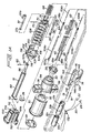
- Fig. 1A is an exploded perspective view of the apparatus of Fig. 1;
- Fig. 2 is a cross-sectional view taken along lines 2-2 of Fig. 1 showing the jaws in the closed position and the needles in the retracted (non-deployed) position;
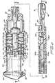
- Fig. 3 is a cross-sectional view taken along lines 3-3 of Fig. 2 showing the jaw actuation mechanism in the proximalmost position corresponding to the closed position of the jaws and the needle driving mechanism in the proximalmost position corresponding to the retracted position of the needles;
- Fig. 3A is a cross-sectional view taken along
lines 3A-3A of Fig. 3 showing the engagement between the front and rear plungers of the jaw actuation mechanism; - Fig. 3B is a cross-sectional view taken along
lines 3B-3B of Fig. 2 showing the jaws in the closed position and the needles in the retracted position; - Fig. 4 is a cross-sectional view taken along lines 4-4 of Fig. 3;
- Fig. 5 is a cross-sectional view taken along lines 5-5 of Fig. 3 showing the connection of the plunger latch and the rear plunger;
- Fig. 6 is a cross-sectional view taken along lines 6-6 of Fig. 3B;
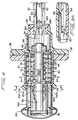
- Fig. 7 is a cross-sectional view similar to Fig. 3 with the jaw actuation mechanism in the advanced position to open the jaws and the needle driving mechanism in the proximalmost position, and also showing release of the safety latch to release the needle driving mechanism;
- Fig. 7A is a cross-sectional view similar to Fig. 3B with the jaws in the open position and the needles in the retracted position;
- Fig. 8 is a cross-sectional view taken along lines 8-8 of Fig. 7 showing retention of the plunger latch in the advanced position to retain the jaws in the open position;
- Fig. 8A is a cross-sectional view similar to Fig. 8 showing release of the plunger latch by the driver stop during advancement of the needle driving mechanism;
- Fig. 8B is a cross-sectional view taken along
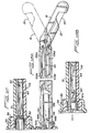
lines 8B-8B of Fig. 9 showing the engagement of the driver stop and the plunger latch when the needle driving mechanism is advanced to deploy the needles; - Fig. 9 is a cross-sectional view similar to Fig. 3 with the jaw actuation mechanism in the advanced position to open the jaws and the needle driving mechanism in the advanced position to deploy the needles;
- Fig. 9A is a cross-sectional view similar to Fig. 3B with the jaws in the open position and the needles in the deployed position;
- Fig. 10 is an enlarged view of a portion of the jaw showing the ferrule prior to engagement by the needle;
- Fig. 11 is an enlarged view of a portion of the jaw showing the frictional engagement of the needle and ferrule when the needles are advanced to the position shown in Fig. 9A;
- Fig. 12 is a cross-sectional view taken along lines 12-12 of Fig. 9 showing the position of the drive pin in the elongated slot of the front plunger prior to retraction of the jaw actuation mechanism to close the jaws;
- Fig. 12A is a view similar to Fig. 7A except showing retraction of the needles after engagement with the ferrules;
- Fig. 12B is a cross-sectional view taken along
lines 12B-12B of Fig. 12A illustrating the position of the drive pin when the needles have been retracted after engagement with the ferrules and the jaws are not yet returned to their closed position; - Fig. 13 is a cross-sectional view similar to Figs. 3 and 3A except showing the needle driving mechanism and the jaw actuation mechanism returned to their initial position after engagement of the needles and ferrules;
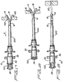
- Fig. 14 is a side view of the surgical suturing apparatus of Fig. 1 prior to introduction through a trocar cannula;
- Fig. 15 is a side view illustrating the surgical apparatus inserted into the body cavity through the trocar cannula;
- Fig. 16 is a side view illustrating the jaws of the apparatus deployed to the open position inside the body cavity;
- Fig. 17 is a side view illustrating placement of the open jaws adjacent the tissue to be sutured;
- Fig. 18 is a side view showing advancement of the needles through the body tissue;
- Fig. 19 is a side view illustrating the surgical apparatus and trocar cannula removed from the body leaving a loop of suture positioned in the tissue;
- Fig. 20 is a side view illustrating the apparatus separated from the suture;
- Fig. 21 shows the suture tied to close the trocar incision;
- Figs. 22-25 illustrate an alternate method of use for the surgical apparatus in which Figs. 22 and 23 illustrate the surgical apparatus re-inserted into the body cavity through a trocar cannula having a cannula mounting apparatus positioned thereon, Fig. 24 illustrates withdrawal of the surgical apparatus after the suture is wrapped around the cannula mounting device to retain the trocar cannula in position; and Fig. 25 illustrates the trocar cannula removed from the tissue and the suture tied to close the trocar incision; and
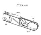
- Fig. 26 is a perspective view of an alternate embodiment of the jaws having a shield.
- Referring now to the drawings and in particular to Fig. 1, a surgical apparatus, designated generally by
reference numeral 10, is provided for closing incisions in body tissue. During endoscopic or laparoscopic procedures, several trocars are inserted through the skin and underlying tissue layers into the body cavity. The trocar typically includes an obturator having a piercing tip and a hollow cannula. After insertion, the obturator is removed, leaving the cannula in place to provide an access port for endoscopic instruments such as staplers, clip appliers, graspers, scissors and other instruments necessary to perform the surgical procedure. In other minimally invasive procedures, the instruments may be inserted directly through the body tissue to access the surgical site without the use of a cannula. In either case, at the end of the surgical procedure, an incision remains through the underlying tissue layers, created by the trocar or by the direct insertion of the instruments, which theapparatus 10 disclosed herein is designed to close. - Referring to Fig. 1, the
apparatus 10 has an elongated body portion orshaft 12 which is dimensioned for insertion through either a trocar cannula or directly into a small incision in the body tissue. A jaw actuation mechanism, which includesactuator 26, is slid forward (distally) to spread thejaws end cap 100, is pressed distally to advance a pair of surgical needles through the body tissue and into the distal end of the jaws. The needles each engage a ferrule connected at opposite ends to a suture and positioned in the distal end of the jaws. In this manner, when the needles are retracted to their initial position, they carry their associated ferrules and connected suture through the body tissue to place the suture on both sides of the trocar incision. The suture is then tensioned and manually tied from outside the body to approximate the tissue on both sides of the trocar incision and to close the incision. - Turning now to the individual components of the
surgical suturing apparatus 10, and with reference to Figs. lA, 2, and 3, the housing portion ofapparatus 10 includes acap housing 30 which is mounted within agrip portion 34. A pair ofwings 36 extend radially fromgrip portion 34 to facilitate grasping by the user. Abushing 38, configured for supportingelongated body portion 12, is seated within acentral bore 33 ofgrip portion 34. Adetent washer 39 is positioned at a distal end ofcap housing 30, in abutment with wall 30a, and is configured to facilitate retention of the rear plunger of the jaw actuation mechanism described below. - The
elongated body portion 12, composed of twobody halves suture 20 is positioned, as shown, in only onesuture receiving channel 31. Proximal anddistal detents body half 12a and proximal anddistal detents body half 12b (see Figs. 7 and 3) for the reasons described below. - Turning now to the jaw actuation mechanism and initially to Fig. 1A, the jaw actuation mechanism is movable between a retracted (proximalmost) position in which the
jaws jaws actuator 26 in the form of a thumb pad, arear plunger 50, afront plunger 54 and aplunger latch 70, all of which are movable between retracted and advanced positions.Plunger return spring 68 is mounted overrear plunger 50 and sandwiched betweenplunger latch 70 anddetent washer 39 to bias the plunger latch 70 (and rear plunger 50) proximally to its retracted position. -
Rear plunger 50 has aradially extending flange 52 at a proximal end for mountingthumb pad 26, and a distally extending flattenedtongue 56 having anopening 58 to receive adrive pin 60. -
Front plunger 54, as shown in Fig. 3A, has an elongatedslot 64 formed at a proximal end to accommodatedrive pin 60. A pair ofprojections arms 65, engage either thedetents shaft 12, depending on the longitudinal position of theplunger 54. That is, in the initial position of theplunger 54,projections proximal detents body halves jaws front plunger 54 is advanced to cam thejaws projections distal detents - As shown in Figs. 1A and 2,
plunger latch 70 has a pair of longitudinally extendingarms 72 terminating inretention tips 73 and a central aperture 74 dimensioned for reception ofrear plunger 50. Mountingpin 75, as shown in Figs. 1A and 5, extends throughaperture 51 inrear plunger 50 and top and bottom openings ofplunger latch 70 to connectplunger latch 70 torear plunger 50. Theplunger latch 70, which advances and retracts along with movement of theplungers - When
thumb pad 26 is slid longitudinally distally,rear plunger 50,plunger latch 70, andfront plunger 54 are likewise slid longitudinally distally. As thefront plunger 54 is advanced, its distal abutting surface 62 (see Fig. 3B) contacts a rear surface of thejaws thumb pad 26,rear plunger 50,front plunger 54 andplunger latch 70 in the proximalmost position with thejaws jaws - It is also contemplated that other mechanisms can be utilized for moving the jaws between open and closed positions. For example, the jaws can be provided with cam slots to receive a camming pin positioned on an actuating rod and a trigger or a pivotable handle mechanism instead of a slidable thumb pad could be utilized. Additionally, the jaws can alternately be normally biased in the open position such that actuation of the jaw actuation mechanism will close the jaws.
- Turning now to the needle driving (actuating) mechanism, and initially to Figs. 1A, 2 and 3, the needle driving mechanism is movable between a retracted (proximalmost) position wherein the
needles jaws needles end cap 100, adriver stop 102, a pair ofneedle drivers wires needles compression spring 108, sandwiched betweendetent washer 39 anddriver stop 102, biases driver stop 102 (and end cap 100) proximally to its retracted position. -
End cap 100, is slidably mounted with respect to caphousing 30 and has anaxial bore 112 for receivingrear plunger 50, agroove 110 to accommodateflange 52 ofrear plunger 50, andchannels assembly latch 37 and safety latch 80 (described below) when theend cap 100 is slid distally withincentral bore 32 ofcap housing 30. During advancement ofthumb pad 26 to advancerear plunger 50 to open thejaws end cap 100 remains stationary asflange 52 slides withingroove 110. -
Driver stop 102 of the needle driving mechanism is seated within a proximal end ofcentral bore 32 ofcap housing 30, and has aproximal flange 116 which is frictionally mounted withinaxial bore 112 ofend cap 100. A pair oflegs 114, each having anindentation 120, extend distally fromdriver stop 102 and interact witharms 72 andretention tips 73 ofplunger latch 70 in a manner described below. Top andbottom grooves assembly latch 37 andsafety latch 80 therethrough to allow unimpeded movement ofdriver stop 102. Top andbottom projections channels 30b formed along the length of the inner surface ofcap housing 30, as best seen in Fig. 4.Central opening 103 accommodatesrear plunger 50. - Needle drivers in the form of
elongated drive rods flanges needle drivers wires needles wires wires jaws - Figures 2 and 3 show the needle driving mechanism in the proximalmost position wherein
head 101 ofend cap 100 is spaced fromcap housing 30,driver stop 102 is positioned within a proximal portion ofcap housing 30, andneedle drivers respective mounting wires surgical needles end cap 100 is pressed distally towardscap housing 30,driver stop 102 andconnected needle drivers - Assembly latch 37 (Figs. 1A and 3) has a
leg 37b which extends throughtop groove 118 ofdriver stop 102 as shown in Fig. 3.Opposing leg 37a is fixed withinannular channel 30b ofcap housing 30, thereby functioning to connect driver stop 102 to thecap housing 30.Leg 37b enters channel llla ofend cap 100 whenend cap 100 is slid distally. - Turning now to the
jaws surgical apparatus 10, and with reference to Figs. 1A, 3B and 7A,jaws body portion 12 viapivot pin 132 extending throughapertures 130. A tissue gap orrecess portion jaw proximal edges abutment surface 62 offront plunger 54 cams the jaws to the open position of Fig. 7A. As shown, the jaws rotate aboutpin 132 in opposite directions. - Referring to Fig. 7A, a
needle guide 133 with anexit opening 137 for thesurgical needle 18 is formed proximal ofrecess portion 142 ofjaw 14. Distal ofrecess portion 142 is anentrance opening 144, and a cutout for receiving oval shapedferrule 24. A suture guide or groove 131 is formed injaw 14 to accommodatesuture 20.Jaw 16, is a mirror image ofjaw 14, and as shown in Fig. 3B has aneedle guide 136, anexit opening 138, anentrance opening 141, a cutout for receiving oval shapedferrule 22 and asuture guide 134. Blunt ends 94, 95 ofjaw apparatus 10 in the body cavity. - As shown, in the open position,
jaws elongated body portion 12. Preferably, the angle is an acute angle of approximately 30° as shown, however, clearly it is contemplated to deploy the jaws to various angles with respect to the longitudinal axis of the body portion. - In the non-deployed position of
needles needle 19 is seated withinneedle guide 136 andneedle 18 is seated withinneedle guide 133 such that pointedtips needle mounting wires wires regions jaws shaft 12, mountingwires -
Suture 20 is attached at one end toferrule 22, wraps through thesuture guide 134 injaw 16, extends throughcentral aperture 132a inpivot pin 132 and throughsuture guide 31 inbody half 12a ofshaft 12. Thesuture 20 is looped at the proximal end ofsuture guide 31 and extends back along the length ofsuture guide 31, back throughcentral aperture 132a inpivot pin 132, around thesuture guide 131 injaw 14 and is attached at its other end toferrule 24. Optionally, the suture guide can extend through an opening in thecap housing 30 so that it can be manually tugged to ensure that theferrules suture guide 31. Extension of the suture through the cap housing also easily accommodates extra length of suture. - When the needle driving mechanism is actuated, and
needle drivers wires open jaws needles exit openings recesses entrance openings jaws needles entrance openings surgical needles suture 20. (see Figs. 9a and 11) Thus, when theneedles exit openings needle tips ferrules suture 20 proximally through the tissue and into the needle guides 133, 136 as shown in Fig. 12A. Note that a mechanical engagement instead of a frictional engagement between the ferrules and needles is also contemplated. - The
apparatus 10 also includes a safety mechanism which prevents deployment of theneedles jaws safety latch 80 in the form of a spring which is normally in the position illustrated in Fig 3.Leg 84 is fixed withinannular channel 30b ofcap housing 30.Step 82 is positioned at the proximal end oflatch 80 and in the initial position abutswall 102b ofdriver stop 102. In this initial blocking position of Fig. 3, if the user attempts to pressend cap 100 distally to advance the needles,wall 102b ofdriver stop 102 will contact step 82 ofsafety latch 80 and be blocked from distal movement. -
Safety latch 80 is automatically moved from a blocking to a non-blocking position upon advancement of the jaw actuating mechanism. More specifically, whenplunger 50 is advanced to move the jaws to the open position, as shown in Fig. 7, thebase portion 71 ofplunger latch 70contacts ramp surface 83 ofsafety latch 80 and forces it downwardly such thatstep 82 is cammed out of engagement with thewall 102b ofdriver stop 102. In this non-blocking position of Fig. 7,step 82 is aligned withgroove 119 ofdriver stop 102 and allows for free movement thereof. Consequently, whenend cap 100 is pressed inwardly to deploy the needles, driver stop 102 can likewise travel distally asgroove 119 passes overstep 82. Thus,driver stop 102 and the associated components of the needle driving mechanism can be advanced to the position of Fig. 9 to deploy the needles. - The use of the apparatus will now be described. In the initial position, the
jaws needles jaws thumb pad 26,rear plunger 50,front plunger 54 andplunger latch 70 are in the retracted (proximalmost) position. Note in this initial position, the raised surfaces ofretention tips 73 ofplunger latch 70 are nested inrecesses 120 oflegs 114 ofdriver stop 102, compression springs 68 and 108 are in the preloaded positions as shown, andprojections front plunger 54 are positioned inrear detents elongated body portion 12. Also, in this initial position,end cap 100,driver stop 102,needle drivers needle mounting wires wall 102b ofdriver stop 102 and step 82 ofsafety latch 80. - When the
apparatus 10 is positioned in the body cavity and the user wishes to deploy thejaws thumb pad 26 is slid distally thereby forcingrear plunger 50,plunger latch 70 andfront plunger 54 distally to the advanced (distalmost) position of Figs. 7 and 7A, compressingspring 68. Note that, asplunger latch 70 is slid distally,wall 71 contacts theramp 83 ofsafety latch 80 tocam step 82 out of engagement withdriver stop 102 in the manner described above. This frees the needle driving mechanism for advancement. Asplunger 54 is advanced, itsabutment surface 62 contacts anglededges jaws front plunger 54,projections 66adistal detents elongated body portion 12 andretention tips 73 ofplunger latch 70 engage aninner wall 39a (Fig. 8) ofdetent washer 39 as shown. This engagement ofplunger latch 70 with the fixedly positionedwasher 39 effectively retains the plunger latch 70 (and the entire jaw actuation mechanism) in the advanced position, thereby ensuring that thejaws - When the apparatus is in the desired position with the body tissue seated in the recessed
portions jaws end cap 100 is pressed inwardly (distally) intocap housing 30, as shown in Fig. 9, thereby forcingdriver stop 102, and theneedle drivers spring 108. Note that movement ofdriver stop 102 is unimpeded bysafety latch 80 becausegroove 119 is aligned withstep 82. Channels llla, lllb ofend cap 100 andgrooves driver stop 102 accommodateassembly latch 37 andsafety latch 80 to allow free travel ofend cap 100 anddriver stop 102. Top andbottom projections driver stop 102 travel alongannular channel 30b ofcap housing 30. - Advancement of
needle drivers advances mounting wires needles wires needles recess portions entrance openings jaws ferrules suture 20. - Note that as shown in Fig. 8A, as driver stop 102 advances distally, it contacts the distal ends of
arms 72 ofplunger latch 70 tocam retention tips 73 out of engagement withinner wall 39a ofdetent washer 39 to thereby releaseplunger latch 70 to allow subsequent retraction. Whendriver stop 102 reaches its distalmost position, as shown in Fig. 8B, the projections ofarms 72 ofplunger latch 70 become re-nested in theindentations 120 oflegs 114 ofdriver stop 102. - After the
needles ferrules needles suture 20 through the body tissue seated into the recess portions of thejaw end cap 100 is released andcompression spring 108 forces it proximally to its initial position. As theend cap 100,driver stop 102 and associatedneedle drivers wires needles ferrules exit openings jaws plunger latch 70 and connectedrear plunger 50 are also retracted due to the nesting ofplunger latch 70 anddriver stop 102 and the biasing force ofcompression spring 68. (Detents front plunger 54 in place whilerear plunger 50 is moving proximally.) However, althoughrear plunger 50 is forced proximally toward its initial position,front plunger 54 does not move initially due to the interaction ofplunger drive pin 60 andelongated slot 64 offront plunger 54. This ensures that theneedles jaws - More specifically, with reference to Figs. 12 and 12b, as
rear plunger 50 moves proximally,drive pin 60 travels proximally inslot 64 offront plunger 54. During this dwell period, thefront plunger 54 remains stationary. When therear plunger 50 is retracted sufficiently so thatdrive pin 60 is at the proximalmost portion of theelongated slot 64 as shown in Fig. 12B, continued retraction ofrear plunger 50 carriesfront plunger 54 to its initial position. In this initial position, theprojections proximal detents elongated body portion 12 to help retain the jaws in the closed position and to provide tactile indication to the user that the jaws are closed. Consequently, the jaw actuation and needle driving mechanisms are returned to the position of Fig. 13. Note that this position is identical to that of Fig. 3, except that theferrules jaws suture 20 has been pulled across therecess portions plunger latch 70 allowssafety latch 80 to return to its original blocking position to block thedriver stop 102. - Figures 14-21 illustrate the use of the
surgical suturing apparatus 10 for closing an incision created by a trocar during an endoscopic/laparoscopic procedure. During endoscopic procedures, where surgery is performed inside the body cavity, one or more trocars are inserted through the body tissue to access the body cavity. A typical trocar includes an obturator having a sharp penetrating tip removably mounted within a cannula. After insertion of the trocar into the body cavity, the obturator is removed leaving the cannula in place to provide an access port for the insertion of various surgical instruments for performing the endoscopic/laproscopic surgical procedure. Figure 14 illustrates thetrocar cannula 200 positioned in the body tissue and theapparatus 10 prior to insertion therethrough. - When it is desired to close the incision created by the trocar, the
surgical apparatus 10 is inserted through thetrocar cannula 200 as illustrated in Fig. 15. - Once inside the body cavity,
thumb pad 26 of the jaw actuation mechanism is slid distally as shown in Fig. 16 to advance the front plunger in the manner described above to spread thejaws trocar cannula 200 and theapparatus 10 are then pulled proximally in the direction of arrow A of Fig. 17 until the body tissue is seated withinrecess portions jaws -
End cap 100 of the needle driving mechanism is then slid distally to advance the needle drivers in the manner described above to advance needles 18 and 19 through the body tissue to engage the ferrules injaws - After deployment of the
needles end cap 100 is released to retractneedles jaws needles suture 20 through the body tissue seated in the recessed portions in the manner described above. - The
instrument 10 andtrocar cannula 200 are then withdrawn together from the body tissue leaving a loop of suture adjacent the innermost tissue layer, e.g. the abdominal fascia, and the suture on both sides of the wound (extending through the fascia and muscle) as shown in Fig. 19.Suture 20 is cut at both ends or pulled (tugged) to separate it from the ferrules (Fig. 20), with the ferrules preferably releasing from the needles before the suture pulls out of the ferrules.Suture 20 is then tensioned to approximate the wound edges and a knot is tied to close the incision as shown in Fig. 21. Consequently, the incision is closed without penetrating the skin layer. Staples and/or separate suture can be manually placed through the skin and closed in the normal fashion. - The jaws may optionally be provided with a shield to maintain pneumoperitoneum and minimize the amount of effluent from the trocar wound when the jaws are retracted to their original position. The shield provides continuity of the apparatus seal to the abdominal wall, even when the jaws are opened and pulled into the wound site. The "spit" shield can be composed of a rigid or flexible material. Figure 26 illustrates one example of a
shield 400 positioned on jaw 16' and overlapping jaw 14'. The shield can alternately include a "skirt" of materiel that resides between the jaws inside the wound, or a gasket on the outside of the wound. - In an alternate use of the
apparatus 10 illustrated in Figs. 22-25, thesuture 20 contained inapparatus 10 is used not only to close the trocar incision but to retain a trocar cannula in position with respect to the body tissue during the surgical procedure. Thesuture 20 is placed in the body tissue, thetrocar cannula 300 andapparatus 10 are removed, and the ferrules are separated from the suture in the same manner as discussed above and as shown in Fig. 20. However, instead of tying the suture to close the incision, theapparatus 10 andtrocar cannula 300 are re-inserted into the incision, with theapparatus 10 serving as a guide for thecannula 300. Thecannula 300 in this embodiment, has either a circumferential groove for accommodating the suture or a separately mounted cannula ring fastening system such as the type described in EP-A-0 589 426. - After the
apparatus 10 andcannula 300 are re-inserted, theapparatus 10 is withdrawn from thecannula 300 and thesuture 20 is wrapped around thecircumferential groove 310 as shown in Fig. 24. Thecannula 300 is then used as an access port for the insertion of the desired endoscopic/laparoscopic instruments to perform the surgical procedure. At the end of the procedure, when it is desired to withdraw the cannula and close the trocar incision, the suture is unwrapped from thegroove 310 and thetrocar cannula 300 and cannula ring fastener are removed. The suture is tied to approximate the wound edges and close the trocar incision as shown in Fig. 25. - It is also contemplated that the
apparatus 10 described herein can be reloadable. That is, after the suture is applied to the body tissue, the ferrules can be removed from the needle tips and a fresh suture with a ferrule attached at each end can be loaded into the jaws of the apparatus. This would enable the apparatus to be used to close a plurality of trocar incisions using the same pair of needles. This embodiment could be provided to the user packaged as a kit with a single sterilized apparatus and several suture/ferrule arrangements. The sutures in the kit could be composed of different material, e.g. absorbable and non-absorbable, so the user could select the desired material. - It should also be understood that the apparatus described herein can be used for closing other wounds and suturing other body tissue in addition to the above-described trocar incisions.
- It will further be understood that various modifications may be made to the embodiments disclosed herein. For example, the jaw actuation mechanism and needle driving mechanism could be biased in a distal direction. Additionally, other mechanisms for opening and closing the jaws, e.g. cam slot and camming pin arrangement, as well as other mechanisms for deploying the needles could be provided. Therefore, the above description should not be construed as limiting but merely as exemplifications of preferred embodiments. Those skilled in the art will envision other modifications within the scope of the claims appended hereto. These claims identify embodiments of the invention additional to those described in detail above.
Claims (16)
- An apparatus for suturing body tissue comprising:an elongated body portion;first and second jaws extending from a distal end portion of the elongated body portion and mounted for relative movement with respect to one another between an open and closed position;first and second needles movable with respect to the first and second jaws;wherein the needles are movable to penetrate body tissue.
- An apparatus for suturing body tissue according to claim 1, further comprising a first actuator operatively associated with the first and second jaws, wherein actuation of the first actuator moves the jaws from a first position to a second position.
- An apparatus for suturing body tissue according to any of the preceding claims, further comprising a second actuator operatively associated with the first and second needles, wherein actuation of the second actuator advances the first and second needles in a distal direction into body tissue.
- An apparatus for suturing body tissue according to any of the preceding claims, wherein in the first position the jaws are closed and in the second position the jaws are spread apart to an angle with respect to the longitudinal axis of the body portion.
- An apparatus for suturing body tissue according to any of the preceding claims, further comprising at least one suture, wherein movement of the needles in a distal direction connects the needles to the at least one suture.
- An apparatus for suturing body tissue according to any of the preceding claims, further comprising a first ferrule positioned in the first jaw and a second ferrule positioned in the second jaw, and a suture connected at one end to the first ferrule and connected at the other end to the second ferrule, wherein actuation of the second actuator to advance the first and second needles advances the first needle into engagement with the first ferrule and the second needle into engagement with the second ferrule.
- An apparatus for suturing body tissue according to any of the preceding claims, wherein the first actuator is slidable longitudinally to move the jaws between the first and second position and further comprising an elongated plunger operatively connected to the first actuator, such that movement of the first actuator longitudinally distally causes a distal end of the plunger to cam the first and second jaws to the second position, wherein in the second position the jaws are spread apart.
- An apparatus for suturing body tissue according to any of the preceding claims, wherein in the second position the jaws are in an open position, and further comprising a safety latch, wherein the safety latch prevents actuation of the second actuator if the jaws are not in the open position.
- An apparatus for suturing body tissue according to claim 8, further comprising a driver member operatively connected to the first actuator, wherein the safety latch has a blocking surface engagable with a portion of the driver member to block movement thereof if the first actuator has not been actuated to move the jaws to the open position, wherein sliding movement of the first actuator to open the jaws automatically cams the safety latch out of blocking engagement with the driver member.
- An apparatus for suturing body tissue according to any of the preceding claims, wherein each of the jaws has a recess portion for receiving body tissue, a needle guide positioned proximally of the recess portion, and a needle engaging member positioned distally of the recess portion and attached to a suture and wherein upon movement of the second actuator, each needle is forced from the needle guide, through the body tissue positioned in the recess portion, and into frictional engagement with the needle engaging member.
- An apparatus for suturing body tissue according to claim 10, wherein upon return of the second actuator to a retracted position, each needle pulls the engaged needle engaging member proximally.
- An apparatus for suturing body tissue comprising:an elongated body portion defining a longitudinal axis and having a proximal end portion and a distal end portion;first and second needles movable with respect to the elongated body portion, the first and second needles being movable in a distal direction and at an angle to the longitudinal axis of the body portion to penetrate body tissue; anda suture initially spaced from the first and second needles, wherein movement of the first and second needles distally connects the first and second needles to the suture.
- An apparatus for suturing body tissue according to claim 12, wherein the suture is connected at each end to a ferrule such that movement of the first and second needles distally moves the needles into engagement with the ferrule to thereby connect the first and second needles to the suture.
- An apparatus for suturing body tissue according to any of the preceding claims, further comprising a pair of elongated drive rods operatively connected to the needles, the drive rods actuable from the proximal end portion of the housing for moving the needles distally.
- An apparatus for suturing body tissue according to any of the preceding claims, further comprising a pair of jaws pivotably mounted to the elongated body portion, wherein each of the jaws contains one of the ferrules.
- An apparatus for suturing body tissue according to any of the preceding claims, wherein the ferrules and suture are removably and replaceably positioned in the apparatus and can be replaced with fresh ferrules and suture.
Applications Claiming Priority (2)
| Application Number | Priority Date | Filing Date | Title |
|---|---|---|---|
| US424946 | 1995-04-19 | ||
| US08/424,946 US5562686A (en) | 1995-04-19 | 1995-04-19 | Apparaus and method for suturing body tissue |
Publications (3)
| Publication Number | Publication Date |
|---|---|
| EP0748612A2 true EP0748612A2 (en) | 1996-12-18 |
| EP0748612A3 EP0748612A3 (en) | 1997-09-24 |
| EP0748612B1 EP0748612B1 (en) | 2003-02-12 |
Family
ID=23684549
Family Applications (1)
| Application Number | Title | Priority Date | Filing Date |
|---|---|---|---|
| EP96106187A Expired - Lifetime EP0748612B1 (en) | 1995-04-19 | 1996-04-19 | Surgical suturing apparatus |
Country Status (5)
| Country | Link |
|---|---|
| US (1) | US5562686A (en) |
| EP (1) | EP0748612B1 (en) |
| CA (1) | CA2173520C (en) |
| DE (1) | DE69626152T2 (en) |
| ES (1) | ES2187590T3 (en) |
Cited By (1)
| Publication number | Priority date | Publication date | Assignee | Title |
|---|---|---|---|---|
| US10595852B2 (en) | 2012-03-21 | 2020-03-24 | Ethicon Llc | Methods and devices for creating tissue plications |
Families Citing this family (349)
| Publication number | Priority date | Publication date | Assignee | Title |
|---|---|---|---|---|
| US6355050B1 (en) | 1992-12-10 | 2002-03-12 | Abbott Laboratories | Device and method for suturing tissue |
| US6036699A (en) | 1992-12-10 | 2000-03-14 | Perclose, Inc. | Device and method for suturing tissue |
| US5527322A (en) | 1993-11-08 | 1996-06-18 | Perclose, Inc. | Device and method for suturing of internal puncture sites |
| US6562052B2 (en) * | 1995-08-24 | 2003-05-13 | Sutura, Inc. | Suturing device and method |
| US6117144A (en) | 1995-08-24 | 2000-09-12 | Sutura, Inc. | Suturing device and method for sealing an opening in a blood vessel or other biological structure |
| IL118969A0 (en) * | 1996-07-29 | 1996-10-31 | Popov Sergey | Purse string suture apparatus |
| US5766183A (en) * | 1996-10-21 | 1998-06-16 | Lasersurge, Inc. | Vascular hole closure |
| US6159224A (en) * | 1996-11-27 | 2000-12-12 | Yoon; Inbae | Multiple needle suturing instrument and method |
| US5759188A (en) * | 1996-11-27 | 1998-06-02 | Yoon; Inbae | Suturing instrument with rotatably mounted needle driver and catcher |
| US5957937A (en) * | 1996-11-27 | 1999-09-28 | Yoon; Inbae | Suturing instrument with spreadable needle holder mounted for arcuate movement |
| US5984932A (en) * | 1996-11-27 | 1999-11-16 | Yoon; Inbae | Suturing instrument with one or more spreadable needle holders mounted for arcuate movement |
| US5993467A (en) * | 1996-11-27 | 1999-11-30 | Yoon; Inbae | Suturing instrument with rotatably mounted spreadable needle holder |
| US5993466A (en) * | 1997-06-17 | 1999-11-30 | Yoon; Inbae | Suturing instrument with multiple rotatably mounted spreadable needle holders |
| US6143005A (en) * | 1997-05-01 | 2000-11-07 | Yoon; Inbae | Suturing instrument with rotatably mounted offset needle holder and method of using the same |
| US6017358A (en) * | 1997-05-01 | 2000-01-25 | Inbae Yoon | Surgical instrument with multiple rotatably mounted offset end effectors |
| US6126665A (en) * | 1997-05-01 | 2000-10-03 | Yoon; Inbae | Surgical instrument with arcuately movable offset end effectors and method of using the same |
| US6004332A (en) * | 1997-05-01 | 1999-12-21 | Yoon; Inbae | Suturing instrument with multiple rotatably mounted offset needle holders and method of using the same |
| US6080180A (en) | 1997-05-01 | 2000-06-27 | Yoon; Inbae | Surgical instrument with rotatably mounted offset end effector and method of using the same |
| US5954731A (en) * | 1997-07-29 | 1999-09-21 | Yoon; Inbae | Surgical instrument with multiple rotatably mounted spreadable end effectors |
| EP1067872B1 (en) | 1998-03-20 | 2006-03-01 | Boston Scientific Limited | Endoscopic suture system |
| US6162209A (en) * | 1998-11-17 | 2000-12-19 | Scimed Life Systems, Inc. | Multi-function surgical instrument tool actuator assembly |
| US20050004576A1 (en) * | 1998-11-23 | 2005-01-06 | Benderev Theodore V. | System for securing sutures, grafts and soft tissue to bone and periosteum |
| US6200330B1 (en) * | 1998-11-23 | 2001-03-13 | Theodore V. Benderev | Systems for securing sutures, grafts and soft tissue to bone and periosteum |
| US7387634B2 (en) * | 1998-11-23 | 2008-06-17 | Benderev Theodore V | System for securing sutures, grafts and soft tissue to bone and periosteum |
| US7410460B2 (en) * | 1998-11-23 | 2008-08-12 | Benderev Theodore V | System for securing sutures, grafts and soft tissue to bone and periosteum |
| US7842048B2 (en) | 2006-08-18 | 2010-11-30 | Abbott Laboratories | Articulating suture device and method |
| US8137364B2 (en) | 2003-09-11 | 2012-03-20 | Abbott Laboratories | Articulating suturing device and method |
| US7235087B2 (en) | 1999-03-04 | 2007-06-26 | Abbott Park | Articulating suturing device and method |
| US20040092964A1 (en) | 1999-03-04 | 2004-05-13 | Modesitt D. Bruce | Articulating suturing device and method |
| US6964668B2 (en) | 1999-03-04 | 2005-11-15 | Abbott Laboratories | Articulating suturing device and method |
| US6136010A (en) * | 1999-03-04 | 2000-10-24 | Perclose, Inc. | Articulating suturing device and method |
| US7001400B1 (en) | 1999-03-04 | 2006-02-21 | Abbott Laboratories | Articulating suturing device and method |
| US6626899B2 (en) | 1999-06-25 | 2003-09-30 | Nidus Medical, Llc | Apparatus and methods for treating tissue |
| US7618426B2 (en) | 2002-12-11 | 2009-11-17 | Usgi Medical, Inc. | Apparatus and methods for forming gastrointestinal tissue approximations |
| US7637905B2 (en) | 2003-01-15 | 2009-12-29 | Usgi Medical, Inc. | Endoluminal tool deployment system |
| US7416554B2 (en) | 2002-12-11 | 2008-08-26 | Usgi Medical Inc | Apparatus and methods for forming and securing gastrointestinal tissue folds |
| US8574243B2 (en) | 1999-06-25 | 2013-11-05 | Usgi Medical, Inc. | Apparatus and methods for forming and securing gastrointestinal tissue folds |
| ATE329531T1 (en) | 1999-07-02 | 2006-07-15 | Quickpass Inc | SURGICAL SEWING DEVICE |
| US6358258B1 (en) | 1999-09-14 | 2002-03-19 | Abbott Laboratories | Device and method for performing end-to-side anastomosis |
| US6190396B1 (en) | 1999-09-14 | 2001-02-20 | Perclose, Inc. | Device and method for deploying and organizing sutures for anastomotic and other attachments |
| US6641592B1 (en) * | 1999-11-19 | 2003-11-04 | Lsi Solutions, Inc. | System for wound closure |
| US8814897B1 (en) | 2000-01-18 | 2014-08-26 | Joseph P. Schultz | Contagion prevention systems |
| US7399304B2 (en) | 2000-03-03 | 2008-07-15 | C.R. Bard, Inc. | Endoscopic tissue apposition device with multiple suction ports |
| US7993368B2 (en) | 2003-03-13 | 2011-08-09 | C.R. Bard, Inc. | Suture clips, delivery devices and methods |
| US8105351B2 (en) | 2001-05-18 | 2012-01-31 | C.R. Bard, Inc. | Method of promoting tissue adhesion |
| US7220266B2 (en) | 2000-05-19 | 2007-05-22 | C. R. Bard, Inc. | Tissue capturing and suturing device and method |
| EP1303218A1 (en) * | 2000-06-14 | 2003-04-23 | Sterilis, Inc. | Suturing method and apparatus |
| US6558399B1 (en) | 2000-06-30 | 2003-05-06 | Abbott Laboratories | Devices and method for handling a plurality of suture elements during a suturing procedure |
| US6533796B1 (en) * | 2000-10-11 | 2003-03-18 | Lsi Solutions, Inc. | Loader for surgical suturing instrument |
| US6730102B1 (en) | 2000-11-06 | 2004-05-04 | Abbott Laboratories | Systems, devices and methods for deploying needles |
| US6692516B2 (en) * | 2000-11-28 | 2004-02-17 | Linvatec Corporation | Knotless suture anchor and method for knotlessly securing tissue |
| US8313496B2 (en) * | 2001-02-02 | 2012-11-20 | Lsi Solutions, Inc. | System for endoscopic suturing |
| US6997931B2 (en) * | 2001-02-02 | 2006-02-14 | Lsi Solutions, Inc. | System for endoscopic suturing |
| DE60236271D1 (en) * | 2001-05-30 | 2010-06-17 | Ams Res Corp | SURGICAL INSTRUMENT FOR IMPLEMENTING A SUTURE |
| WO2003000141A1 (en) | 2001-06-25 | 2003-01-03 | Abbott Laboratories | Apparatus and methods for performing an anastomosis |
| US6719764B1 (en) | 2001-08-24 | 2004-04-13 | Scimed Life Systems, Inc. | Forward deploying suturing device and methods of use |
| US7879046B2 (en) | 2001-10-01 | 2011-02-01 | Depuy Mitek, Inc. | Suturing apparatus and method |
| JP4489428B2 (en) * | 2001-10-01 | 2010-06-23 | サージカル ソリューションズ リミテッド ライアビリティ カンパニー | Suture device |
| US20030078601A1 (en) * | 2001-10-22 | 2003-04-24 | Oleg Shikhman | Crimping and cutting device |
| DE60239559D1 (en) * | 2001-10-22 | 2011-05-05 | Interventional Therapies Llc | WUNDNÄHVORRICHTUNG |
| ATE326906T1 (en) * | 2001-10-23 | 2006-06-15 | Arthrex Inc | SURGICAL DEVICE FOR SEWING TISSUE |
| US7118583B2 (en) * | 2001-10-23 | 2006-10-10 | Arthrex, Inc. | Meniscal suturing instrument and method |
| US6921408B2 (en) * | 2002-03-12 | 2005-07-26 | Lsi Solutions, Inc. | Apparatus for sewing tissue and method of use |
| US6984237B2 (en) | 2002-05-22 | 2006-01-10 | Orthopaedic Biosystems Ltd., Inc. | Suture passing surgical instrument |
| US20030225423A1 (en) * | 2002-05-30 | 2003-12-04 | Huitema Thomas W. | Surgical clip |
| US7232447B2 (en) | 2002-06-12 | 2007-06-19 | Boston Scientific Scimed, Inc. | Suturing instrument with deflectable head |
| US20040167547A1 (en) * | 2002-07-03 | 2004-08-26 | Beane Richard M. | Surgical suture placement device |
| US6936054B2 (en) * | 2002-07-22 | 2005-08-30 | Boston Scientific Scimed, Inc. | Placing sutures |
| AU2003272289A1 (en) | 2002-09-06 | 2004-03-29 | C.R. Bard, Inc. | Integrated endoscope and accessory treatment device |
| US7942884B2 (en) | 2002-12-11 | 2011-05-17 | Usgi Medical, Inc. | Methods for reduction of a gastric lumen |
| US7942898B2 (en) | 2002-12-11 | 2011-05-17 | Usgi Medical, Inc. | Delivery systems and methods for gastric reduction |
| US7160309B2 (en) | 2002-12-31 | 2007-01-09 | Laveille Kao Voss | Systems for anchoring a medical device in a body lumen |
| US8016845B1 (en) | 2003-02-04 | 2011-09-13 | Lsi Solutions, Inc. | Instrument for guiding the surgical cutting of tissue and method of use |
| US7833237B2 (en) * | 2003-02-04 | 2010-11-16 | Lsi Solutions, Inc. | Instrument for assisting in the remote placement of tied surgical knots and trimming of suture away from the knot and method of use |
| US7481817B2 (en) | 2003-02-13 | 2009-01-27 | Lsi Soultions, Inc. | Instrument for surgically cutting tissue and method of use |
| BRPI0410376B1 (en) | 2003-05-16 | 2016-06-14 | Bard Inc C R | endoscopic suture system and single intubation |
| US7935128B2 (en) * | 2003-05-21 | 2011-05-03 | Boston Scientific Scimed, Inc. | Remotely-reloadable suturing device |
| AU2004245108B2 (en) | 2003-06-06 | 2010-03-11 | Abbott Laboratories | Sizing and positioning adapter for medical instruments |
| US8216252B2 (en) | 2004-05-07 | 2012-07-10 | Usgi Medical, Inc. | Tissue manipulation and securement system |
| US8308765B2 (en) | 2004-05-07 | 2012-11-13 | Usgi Medical, Inc. | Apparatus and methods for positioning and securing anchors |
| US7462188B2 (en) | 2003-09-26 | 2008-12-09 | Abbott Laboratories | Device and method for suturing intracardiac defects |
| US7361180B2 (en) | 2004-05-07 | 2008-04-22 | Usgi Medical, Inc. | Apparatus for manipulating and securing tissue |
| US7347863B2 (en) | 2004-05-07 | 2008-03-25 | Usgi Medical, Inc. | Apparatus and methods for manipulating and securing tissue |
| US20050251189A1 (en) | 2004-05-07 | 2005-11-10 | Usgi Medical Inc. | Multi-position tissue manipulation assembly |
| US7449024B2 (en) | 2003-12-23 | 2008-11-11 | Abbott Laboratories | Suturing device with split arm and method of suturing tissue |
| US7608092B1 (en) | 2004-02-20 | 2009-10-27 | Biomet Sports Medicince, LLC | Method and apparatus for performing meniscus repair |
| US7976539B2 (en) | 2004-03-05 | 2011-07-12 | Hansen Medical, Inc. | System and method for denaturing and fixing collagenous tissue |
| US7703459B2 (en) | 2004-03-09 | 2010-04-27 | Usgi Medical, Inc. | Apparatus and methods for mapping out endoluminal gastrointestinal surgery |
| US8444657B2 (en) | 2004-05-07 | 2013-05-21 | Usgi Medical, Inc. | Apparatus and methods for rapid deployment of tissue anchors |
| US7736374B2 (en) | 2004-05-07 | 2010-06-15 | Usgi Medical, Inc. | Tissue manipulation and securement system |
| US7918869B2 (en) | 2004-05-07 | 2011-04-05 | Usgi Medical, Inc. | Methods and apparatus for performing endoluminal gastroplasty |
| US7520884B2 (en) | 2004-05-07 | 2009-04-21 | Usgi Medical Inc. | Methods for performing gastroplasty |
| US8257394B2 (en) | 2004-05-07 | 2012-09-04 | Usgi Medical, Inc. | Apparatus and methods for positioning and securing anchors |
| US7695493B2 (en) | 2004-06-09 | 2010-04-13 | Usgi Medical, Inc. | System for optimizing anchoring force |
| US8206417B2 (en) | 2004-06-09 | 2012-06-26 | Usgi Medical Inc. | Apparatus and methods for optimizing anchoring force |
| US7678135B2 (en) | 2004-06-09 | 2010-03-16 | Usgi Medical, Inc. | Compressible tissue anchor assemblies |
| US7736379B2 (en) | 2004-06-09 | 2010-06-15 | Usgi Medical, Inc. | Compressible tissue anchor assemblies |
| US7931661B2 (en) | 2004-06-14 | 2011-04-26 | Usgi Medical, Inc. | Apparatus and methods for performing transluminal gastrointestinal procedures |
| US8992549B2 (en) * | 2004-08-05 | 2015-03-31 | Teleflex Medical Incorporated | Laparoscopic port site closure tool |
| US8123762B2 (en) | 2004-08-19 | 2012-02-28 | Boston Scientific Scimed, Inc. | Suturing instrument |
| EP1804677B1 (en) * | 2004-09-27 | 2018-01-03 | Nobles Medical Technologies, Inc. | Handle for suturing apparatus |
| US8088130B2 (en) | 2006-02-03 | 2012-01-03 | Biomet Sports Medicine, Llc | Method and apparatus for coupling soft tissue to a bone |
| US9017381B2 (en) | 2007-04-10 | 2015-04-28 | Biomet Sports Medicine, Llc | Adjustable knotless loops |
| US8840645B2 (en) | 2004-11-05 | 2014-09-23 | Biomet Sports Medicine, Llc | Method and apparatus for coupling soft tissue to a bone |
| US8137382B2 (en) | 2004-11-05 | 2012-03-20 | Biomet Sports Medicine, Llc | Method and apparatus for coupling anatomical features |
| US7601165B2 (en) | 2006-09-29 | 2009-10-13 | Biomet Sports Medicine, Llc | Method and apparatus for forming a self-locking adjustable suture loop |
| US8118836B2 (en) | 2004-11-05 | 2012-02-21 | Biomet Sports Medicine, Llc | Method and apparatus for coupling soft tissue to a bone |
| US9801708B2 (en) | 2004-11-05 | 2017-10-31 | Biomet Sports Medicine, Llc | Method and apparatus for coupling soft tissue to a bone |
| US7905904B2 (en) | 2006-02-03 | 2011-03-15 | Biomet Sports Medicine, Llc | Soft tissue repair device and associated methods |
| US8361113B2 (en) | 2006-02-03 | 2013-01-29 | Biomet Sports Medicine, Llc | Method and apparatus for coupling soft tissue to a bone |
| US8303604B2 (en) | 2004-11-05 | 2012-11-06 | Biomet Sports Medicine, Llc | Soft tissue repair device and method |
| US8298262B2 (en) | 2006-02-03 | 2012-10-30 | Biomet Sports Medicine, Llc | Method for tissue fixation |
| US20060189993A1 (en) | 2004-11-09 | 2006-08-24 | Arthrotek, Inc. | Soft tissue conduit device |
| US7905903B2 (en) | 2006-02-03 | 2011-03-15 | Biomet Sports Medicine, Llc | Method for tissue fixation |
| US7749250B2 (en) | 2006-02-03 | 2010-07-06 | Biomet Sports Medicine, Llc | Soft tissue repair assembly and associated method |
| US7909851B2 (en) | 2006-02-03 | 2011-03-22 | Biomet Sports Medicine, Llc | Soft tissue repair device and associated methods |
| US7857830B2 (en) | 2006-02-03 | 2010-12-28 | Biomet Sports Medicine, Llc | Soft tissue repair and conduit device |
| US8128658B2 (en) | 2004-11-05 | 2012-03-06 | Biomet Sports Medicine, Llc | Method and apparatus for coupling soft tissue to bone |
| US8998949B2 (en) | 2004-11-09 | 2015-04-07 | Biomet Sports Medicine, Llc | Soft tissue conduit device |
| US8298291B2 (en) | 2005-05-26 | 2012-10-30 | Usgi Medical, Inc. | Methods and apparatus for securing and deploying tissue anchors |
| US9585651B2 (en) | 2005-05-26 | 2017-03-07 | Usgi Medical, Inc. | Methods and apparatus for securing and deploying tissue anchors |
| AU2006262498B2 (en) | 2005-06-20 | 2011-11-03 | Nobles Medical Technologies, Inc. | Method and apparatus for applying a knot to a suture |
| US20060293699A1 (en) * | 2005-06-28 | 2006-12-28 | Boston Scientific Scimed, Inc | Low profile suturing instrument |
| US8083754B2 (en) | 2005-08-08 | 2011-12-27 | Abbott Laboratories | Vascular suturing device with needle capture |
| US8267947B2 (en) | 2005-08-08 | 2012-09-18 | Abbott Laboratories | Vascular suturing device |
| US7883517B2 (en) | 2005-08-08 | 2011-02-08 | Abbott Laboratories | Vascular suturing device |
| US8920442B2 (en) | 2005-08-24 | 2014-12-30 | Abbott Vascular Inc. | Vascular opening edge eversion methods and apparatuses |
| US20070060895A1 (en) | 2005-08-24 | 2007-03-15 | Sibbitt Wilmer L Jr | Vascular closure methods and apparatuses |
| US9456811B2 (en) | 2005-08-24 | 2016-10-04 | Abbott Vascular Inc. | Vascular closure methods and apparatuses |
| WO2007025302A2 (en) * | 2005-08-26 | 2007-03-01 | G-Surge Medical Solutions, Inc. | Suturing apparatus and methods |
| US7632308B2 (en) | 2005-11-23 | 2009-12-15 | Didier Loulmet | Methods, devices, and kits for treating mitral valve prolapse |
| US8726909B2 (en) | 2006-01-27 | 2014-05-20 | Usgi Medical, Inc. | Methods and apparatus for revision of obesity procedures |
| US11311287B2 (en) | 2006-02-03 | 2022-04-26 | Biomet Sports Medicine, Llc | Method for tissue fixation |
| US8597327B2 (en) | 2006-02-03 | 2013-12-03 | Biomet Manufacturing, Llc | Method and apparatus for sternal closure |
| US9149267B2 (en) | 2006-02-03 | 2015-10-06 | Biomet Sports Medicine, Llc | Method and apparatus for coupling soft tissue to a bone |
| US8506597B2 (en) | 2011-10-25 | 2013-08-13 | Biomet Sports Medicine, Llc | Method and apparatus for interosseous membrane reconstruction |
| US8936621B2 (en) | 2006-02-03 | 2015-01-20 | Biomet Sports Medicine, Llc | Method and apparatus for forming a self-locking adjustable loop |
| US8801783B2 (en) | 2006-09-29 | 2014-08-12 | Biomet Sports Medicine, Llc | Prosthetic ligament system for knee joint |
| US8771352B2 (en) | 2011-05-17 | 2014-07-08 | Biomet Sports Medicine, Llc | Method and apparatus for tibial fixation of an ACL graft |
| US8251998B2 (en) | 2006-08-16 | 2012-08-28 | Biomet Sports Medicine, Llc | Chondral defect repair |
| US9538998B2 (en) | 2006-02-03 | 2017-01-10 | Biomet Sports Medicine, Llc | Method and apparatus for fracture fixation |
| US9271713B2 (en) | 2006-02-03 | 2016-03-01 | Biomet Sports Medicine, Llc | Method and apparatus for tensioning a suture |
| US11259792B2 (en) | 2006-02-03 | 2022-03-01 | Biomet Sports Medicine, Llc | Method and apparatus for coupling anatomical features |
| US8562645B2 (en) | 2006-09-29 | 2013-10-22 | Biomet Sports Medicine, Llc | Method and apparatus for forming a self-locking adjustable loop |
| US8652171B2 (en) | 2006-02-03 | 2014-02-18 | Biomet Sports Medicine, Llc | Method and apparatus for soft tissue fixation |
| US8562647B2 (en) | 2006-09-29 | 2013-10-22 | Biomet Sports Medicine, Llc | Method and apparatus for securing soft tissue to bone |
| US8652172B2 (en) | 2006-02-03 | 2014-02-18 | Biomet Sports Medicine, Llc | Flexible anchors for tissue fixation |
| US8574235B2 (en) | 2006-02-03 | 2013-11-05 | Biomet Sports Medicine, Llc | Method for trochanteric reattachment |
| US7959650B2 (en) | 2006-09-29 | 2011-06-14 | Biomet Sports Medicine, Llc | Adjustable knotless loops |
| US8968364B2 (en) | 2006-02-03 | 2015-03-03 | Biomet Sports Medicine, Llc | Method and apparatus for fixation of an ACL graft |
| US10517587B2 (en) | 2006-02-03 | 2019-12-31 | Biomet Sports Medicine, Llc | Method and apparatus for forming a self-locking adjustable loop |
| US9078644B2 (en) | 2006-09-29 | 2015-07-14 | Biomet Sports Medicine, Llc | Fracture fixation device |
| US9005220B2 (en) | 2006-04-04 | 2015-04-14 | C.R. Bard, Inc. | Suturing devices and methods with energy emitting elements |
| US8870916B2 (en) | 2006-07-07 | 2014-10-28 | USGI Medical, Inc | Low profile tissue anchors, tissue anchor systems, and methods for their delivery and use |
| AU2007280012B2 (en) | 2006-07-31 | 2013-01-31 | T.A.G. Medical Devices - Agriculture Cooperative Ltd. | Arthroscopic bone transplanting procedure, and medical instruments useful therein |
| US20080045976A1 (en) * | 2006-08-16 | 2008-02-21 | Wilson-Cook Medical Inc. | Suturing device |
| US8500818B2 (en) | 2006-09-29 | 2013-08-06 | Biomet Manufacturing, Llc | Knee prosthesis assembly with ligament link |
| US9918826B2 (en) | 2006-09-29 | 2018-03-20 | Biomet Sports Medicine, Llc | Scaffold for spring ligament repair |
| US8672969B2 (en) | 2006-09-29 | 2014-03-18 | Biomet Sports Medicine, Llc | Fracture fixation device |
| US11259794B2 (en) | 2006-09-29 | 2022-03-01 | Biomet Sports Medicine, Llc | Method for implanting soft tissue |
| EP2083702B1 (en) | 2006-10-05 | 2019-02-13 | Covidien LP | Axial stitching device |
| JP5481194B2 (en) | 2006-10-05 | 2014-04-23 | コヴィディエン リミテッド パートナーシップ | Flexible endoscopic suturing device |
| EP2083706B1 (en) | 2006-11-07 | 2012-02-01 | Boston Scientific Limited | Delivering sutures |
| EP1938758B1 (en) * | 2006-12-28 | 2018-08-29 | Olympus Corporation | Endoscopic treatment tool |
| US9370368B2 (en) * | 2006-12-29 | 2016-06-21 | Ashok Kumar Jayant | Device for dispensing, looping and tying ligatures |
| EP2134266A4 (en) | 2007-03-29 | 2015-06-03 | Nobles Medical Technologies Inc | Suturing devices and methods for closing a patent foramen ovale |
| WO2008124676A1 (en) * | 2007-04-06 | 2008-10-16 | Interventional Therapies | Suturing, crimping and cutting device |
| US8672954B2 (en) * | 2007-05-30 | 2014-03-18 | T.A.G. Medical Devices—Agriculture Cooperative Ltd. | Piercing implement particularly useful as a medical implement for piercing body tissue, and method of using such implement for applying a suture to the body tissue |
| US8574244B2 (en) | 2007-06-25 | 2013-11-05 | Abbott Laboratories | System for closing a puncture in a vessel wall |
| US8465505B2 (en) | 2011-05-06 | 2013-06-18 | Ceterix Orthopaedics, Inc. | Suture passer devices and methods |
| US9314234B2 (en) | 2007-07-03 | 2016-04-19 | Ceterix Orthopaedics, Inc. | Pre-tied surgical knots for use with suture passers |
| US9861354B2 (en) | 2011-05-06 | 2018-01-09 | Ceterix Orthopaedics, Inc. | Meniscus repair |
| US8702731B2 (en) | 2007-07-03 | 2014-04-22 | Ceterix Orthopaedics, Inc. | Suturing and repairing tissue using in vivo suture loading |
| US8500809B2 (en) | 2011-01-10 | 2013-08-06 | Ceterix Orthopaedics, Inc. | Implant and method for repair of the anterior cruciate ligament |
| US9211119B2 (en) | 2007-07-03 | 2015-12-15 | Ceterix Orthopaedics, Inc. | Suture passers and methods of passing suture |
| US10441273B2 (en) | 2007-07-03 | 2019-10-15 | Ceterix Orthopaedics, Inc. | Pre-tied surgical knots for use with suture passers |
| US8911456B2 (en) | 2007-07-03 | 2014-12-16 | Ceterix Orthopaedics, Inc. | Methods and devices for preventing tissue bridging while suturing |
| US8663253B2 (en) | 2007-07-03 | 2014-03-04 | Ceterix Orthopaedics, Inc. | Methods of meniscus repair |
| US9005238B2 (en) | 2007-08-23 | 2015-04-14 | Covidien Lp | Endoscopic surgical devices |
| US7967795B1 (en) | 2010-01-19 | 2011-06-28 | Lamodel Ltd. | Cartridge interface assembly with driving plunger |
| US9656019B2 (en) | 2007-10-02 | 2017-05-23 | Medimop Medical Projects Ltd. | Apparatuses for securing components of a drug delivery system during transport and methods of using same |
| CN101868273B (en) | 2007-10-02 | 2014-10-15 | 莱蒙德尔有限公司 | External drug pump |
| US10420880B2 (en) | 2007-10-02 | 2019-09-24 | West Pharma. Services IL, Ltd. | Key for securing components of a drug delivery system during assembly and/or transport and methods of using same |
| US9345836B2 (en) | 2007-10-02 | 2016-05-24 | Medimop Medical Projects Ltd. | Disengagement resistant telescoping assembly and unidirectional method of assembly for such |
| WO2009061504A1 (en) | 2007-11-05 | 2009-05-14 | Revolutionary Surgical Device, Llc | Suture passing instrument and method |
| US8864776B2 (en) | 2008-04-11 | 2014-10-21 | Covidien Lp | Deployment system for surgical suture |
| US20100228270A1 (en) * | 2008-04-11 | 2010-09-09 | Michael Bogart | Deployment System for Surgical Suture |
| EP2291125B1 (en) | 2008-05-09 | 2021-04-21 | Nobles Medical Technologies, Inc. | Suturing devices for suturing an anatomic valve |
| WO2009151815A1 (en) * | 2008-06-11 | 2009-12-17 | Boston Scientific Scimed, Inc. | Suturing instrument and method for uterine preservation |
| US8628545B2 (en) | 2008-06-13 | 2014-01-14 | Covidien Lp | Endoscopic stitching devices |
| US20110040308A1 (en) | 2008-06-13 | 2011-02-17 | Ramiro Cabrera | Endoscopic Stitching Devices |
| US8579921B2 (en) * | 2008-06-18 | 2013-11-12 | Covidien Lp | Spring-type suture securing device |
| US12097357B2 (en) | 2008-09-15 | 2024-09-24 | West Pharma. Services IL, Ltd. | Stabilized pen injector |
| US9393369B2 (en) | 2008-09-15 | 2016-07-19 | Medimop Medical Projects Ltd. | Stabilized pen injector |
| CA2738426C (en) | 2008-09-29 | 2016-03-15 | C.R. Bard, Inc. | Endoscopic suturing device |
| US8926639B2 (en) | 2009-01-12 | 2015-01-06 | Teleflex Medical Incorporated | Apparatus and methods for tissue closure |
| US8177796B2 (en) | 2009-03-23 | 2012-05-15 | Linvatec Corporation | Suture passing apparatus and method |
| US9943306B2 (en) | 2009-04-14 | 2018-04-17 | Covidien Lp | Knotless endostitch suture retainer |
| US8343227B2 (en) | 2009-05-28 | 2013-01-01 | Biomet Manufacturing Corp. | Knee prosthesis assembly with ligament link |
| US12096928B2 (en) | 2009-05-29 | 2024-09-24 | Biomet Sports Medicine, Llc | Method and apparatus for coupling soft tissue to a bone |
| USD708746S1 (en) | 2009-06-10 | 2014-07-08 | Covidien Lp | Handle for surgical device |
| US20100324597A1 (en) * | 2009-06-19 | 2010-12-23 | Oleg Shikhman | Crimping and cutting device |
| US8597262B2 (en) | 2009-07-09 | 2013-12-03 | Ams Research Corporation | Apparatus and methods of treatment of pathologic proliferative conditions uterine tissue |
| DK200970073A (en) * | 2009-07-22 | 2011-01-23 | Coloplast As | Suturing system and assembly |
| US10071198B2 (en) | 2012-11-02 | 2018-09-11 | West Pharma. Servicees IL, Ltd. | Adhesive structure for medical device |
| US8157769B2 (en) | 2009-09-15 | 2012-04-17 | Medimop Medical Projects Ltd. | Cartridge insertion assembly for drug delivery system |
| USD810279S1 (en) | 2009-09-15 | 2018-02-13 | Medimop Medical Projects Ltd. | Injector device |
| US10071196B2 (en) | 2012-05-15 | 2018-09-11 | West Pharma. Services IL, Ltd. | Method for selectively powering a battery-operated drug-delivery device and device therefor |
| US8591529B2 (en) | 2009-10-01 | 2013-11-26 | Covidien Lp | Wound closure device including direct-driven needle |
| US8490713B2 (en) | 2009-10-06 | 2013-07-23 | Covidien Lp | Handle assembly for endoscopic suturing device |
| WO2011057245A2 (en) | 2009-11-09 | 2011-05-12 | Suturepro Technologies, Inc. | Devices, systems and methods for meniscus repair |
| US11744575B2 (en) | 2009-11-09 | 2023-09-05 | Ceterix Orthopaedics, Inc. | Suture passer devices and methods |
| US9011454B2 (en) | 2009-11-09 | 2015-04-21 | Ceterix Orthopaedics, Inc. | Suture passer with radiused upper jaw |
| US9848868B2 (en) | 2011-01-10 | 2017-12-26 | Ceterix Orthopaedics, Inc. | Suture methods for forming locking loops stitches |
| US8348898B2 (en) | 2010-01-19 | 2013-01-08 | Medimop Medical Projects Ltd. | Automatic needle for drug pump |
| US8257366B2 (en) * | 2010-02-08 | 2012-09-04 | Coloplast A/S | Digital suture fixation system |
| US20110196389A1 (en) * | 2010-02-09 | 2011-08-11 | Coloplast A/S | Digital suture fixation system |
| EP2569031B1 (en) | 2010-05-10 | 2017-10-11 | Medimop Medical Projects Ltd. | Low volume accurate injector |
| US9370353B2 (en) | 2010-09-01 | 2016-06-21 | Abbott Cardiovascular Systems, Inc. | Suturing devices and methods |
| US8663252B2 (en) | 2010-09-01 | 2014-03-04 | Abbott Cardiovascular Systems, Inc. | Suturing devices and methods |
| US9913638B2 (en) | 2011-01-10 | 2018-03-13 | Ceterix Orthopaedics, Inc. | Transosteal anchoring methods for tissue repair |
| US8556916B2 (en) | 2011-02-14 | 2013-10-15 | Smith & Nephew, Inc. | Method and device for suture manipulation |
| US8968340B2 (en) | 2011-02-23 | 2015-03-03 | Covidien Lp | Single actuating jaw flexible endolumenal stitching device |
| WO2012121877A1 (en) | 2011-03-10 | 2012-09-13 | Boston Scientific Scimed, Inc. | Flexible suturing instrument |
| USD702834S1 (en) | 2011-03-22 | 2014-04-15 | Medimop Medical Projects Ltd. | Cartridge for use in injection device |
| CN110882021A (en) | 2011-04-15 | 2020-03-17 | 心脏缝合有限公司 | Suturing device and method for suturing an anatomical valve |
| US9241708B2 (en) | 2011-06-07 | 2016-01-26 | St. Jude Medical Puerto Rico, Llc | Large bore closure device and methods |
| US8951263B2 (en) | 2011-07-08 | 2015-02-10 | Smith & Nephew, Inc. | Orthopedic suture passer and method |
| US9662105B2 (en) | 2011-07-08 | 2017-05-30 | Smith & Nephew, Inc. | Suture passer and method |
| US9357997B2 (en) | 2011-07-08 | 2016-06-07 | Smith & Nephew, Inc. | Suture passer and method |
| US8801727B2 (en) | 2011-07-08 | 2014-08-12 | Smith & Nephew, Inc. | Orthopedic suture passer and method |
| US8882834B2 (en) | 2011-07-08 | 2014-11-11 | Smith & Nephew, Inc. | Soft tissue repair |
| US8888849B2 (en) | 2011-07-08 | 2014-11-18 | Smith & Nephew, Inc. | Soft tissue repair |
| US8992550B2 (en) * | 2011-07-20 | 2015-03-31 | Coloplast A/S | Suture system with capsule eyelet providing multiple suture tissue fixation |
| US20130035701A1 (en) | 2011-08-04 | 2013-02-07 | Suture Ease, LLC | Dual insufflation and wound closure devices ans methods |
| US10524778B2 (en) | 2011-09-28 | 2020-01-07 | Ceterix Orthopaedics | Suture passers adapted for use in constrained regions |
| US10537321B2 (en) | 2014-04-08 | 2020-01-21 | Ceterix Orthopaedics, Inc. | Suture passers adapted for use in constrained regions |
| US9357991B2 (en) | 2011-11-03 | 2016-06-07 | Biomet Sports Medicine, Llc | Method and apparatus for stitching tendons |
| US9314241B2 (en) | 2011-11-10 | 2016-04-19 | Biomet Sports Medicine, Llc | Apparatus for coupling soft tissue to a bone |
| US9370350B2 (en) | 2011-11-10 | 2016-06-21 | Biomet Sports Medicine, Llc | Apparatus for coupling soft tissue to a bone |
| US9381013B2 (en) | 2011-11-10 | 2016-07-05 | Biomet Sports Medicine, Llc | Method for coupling soft tissue to a bone |
| WO2013074490A1 (en) | 2011-11-16 | 2013-05-23 | St. Jude Medical Puerto Rico Llc | Large bore vascular closure device with inner and outer seals |
| WO2013074488A1 (en) | 2011-11-16 | 2013-05-23 | St. Jude Medical Puerto Rico Llc | Vascular closure system |
| WO2013081905A1 (en) | 2011-11-28 | 2013-06-06 | St. Jude Medical Puerto Rico Llc | Anchor device for large bore vascular closure |
| US9017346B2 (en) * | 2011-12-14 | 2015-04-28 | Msk, Llc | Automated suture device |
| US9113879B2 (en) | 2011-12-15 | 2015-08-25 | Ethicon Endo-Surgery, Inc. | Devices and methods for endoluminal plication |
| US9113867B2 (en) | 2011-12-15 | 2015-08-25 | Ethicon Endo-Surgery, Inc. | Devices and methods for endoluminal plication |
| US9259217B2 (en) | 2012-01-03 | 2016-02-16 | Biomet Manufacturing, Llc | Suture Button |
| WO2013103682A2 (en) | 2012-01-04 | 2013-07-11 | Teleflex Medical Incorporated | Apparatus and methods for tissue closure |
| US9572566B2 (en) | 2012-02-29 | 2017-02-21 | Marker Medical, Llc | Surgical suturing apparatus and method |
| US9358077B2 (en) | 2012-03-14 | 2016-06-07 | St. Jude Medical Puerto Rico Llc | Markers for tissue tract depth indication and methods |
| US9072827B2 (en) | 2012-03-26 | 2015-07-07 | Medimop Medical Projects Ltd. | Fail safe point protector for needle safety flap |
| US8858573B2 (en) | 2012-04-10 | 2014-10-14 | Abbott Cardiovascular Systems, Inc. | Apparatus and method for suturing body lumens |
| US8864778B2 (en) | 2012-04-10 | 2014-10-21 | Abbott Cardiovascular Systems, Inc. | Apparatus and method for suturing body lumens |
| US9265514B2 (en) | 2012-04-17 | 2016-02-23 | Miteas Ltd. | Manipulator for grasping tissue |
| US20130304096A1 (en) * | 2012-05-02 | 2013-11-14 | The Johns Hopkins University | Fascial closure suture device |
| EP3597115A1 (en) | 2012-05-11 | 2020-01-22 | Heartstitch, Inc. | Suturing devices for suturing an anatomic structure |
| US9241707B2 (en) | 2012-05-31 | 2016-01-26 | Abbott Cardiovascular Systems, Inc. | Systems, methods, and devices for closing holes in body lumens |
| WO2014021937A1 (en) | 2012-08-03 | 2014-02-06 | St. Jude Medical Puerto Rico Llc | Large bore introducer with improved seal |
| WO2014031147A1 (en) | 2012-08-24 | 2014-02-27 | St. Jude Medical Puerto Rico Llc | Balloon bailout and bioadhesive delivery device for suture based closure and methods |
| IL221634A0 (en) | 2012-08-26 | 2012-12-31 | Medimop Medical Projects Ltd | Universal drug vial adapter |
| US9421323B2 (en) | 2013-01-03 | 2016-08-23 | Medimop Medical Projects Ltd. | Door and doorstop for portable one use drug delivery apparatus |
| US9757119B2 (en) | 2013-03-08 | 2017-09-12 | Biomet Sports Medicine, Llc | Visual aid for identifying suture limbs arthroscopically |
| US10136885B2 (en) | 2013-03-11 | 2018-11-27 | St. Jude Medical Puerto Rico Llc | Three suture large bore closure device and methods |
| US9055933B2 (en) | 2013-03-12 | 2015-06-16 | St. Jude Medical Puerto Rico Llc | Large bore closure secondary hemostasis bioadhesive delivery systems and methods |
| US9918827B2 (en) | 2013-03-14 | 2018-03-20 | Biomet Sports Medicine, Llc | Scaffold for spring ligament repair |
| US9357984B2 (en) | 2013-04-23 | 2016-06-07 | Covidien Lp | Constant value gap stabilizer for articulating links |
| US9011164B2 (en) | 2013-04-30 | 2015-04-21 | Medimop Medical Projects Ltd. | Clip contact for easy installation of printed circuit board PCB |
| US10828022B2 (en) | 2013-07-02 | 2020-11-10 | Med-Venture Investments, Llc | Suturing devices and methods for suturing an anatomic structure |
| WO2015009840A1 (en) * | 2013-07-16 | 2015-01-22 | Suture Ease, Inc. | Suture apparatus, system and method |
| DE212014000169U1 (en) | 2013-08-07 | 2016-03-14 | Medimop Medical Projects Ltd. | Fluid transfer devices for use with infusion fluid containers |
| US9247935B2 (en) | 2013-09-23 | 2016-02-02 | Ceterix Orthopaedics, Inc. | Arthroscopic knot pusher and suture cutter |
| EP3079602B1 (en) | 2013-12-06 | 2020-01-22 | Med-venture Investments, LLC | Suturing apparatuses |
| WO2015095133A1 (en) | 2013-12-16 | 2015-06-25 | Ceterix Orthopaedics, Inc. | Automatically reloading suture passer devices having pre-tied knots and methods |
| US10136886B2 (en) | 2013-12-20 | 2018-11-27 | Biomet Sports Medicine, Llc | Knotless soft tissue devices and techniques |
| US9554781B2 (en) | 2014-01-23 | 2017-01-31 | Lsi Solutions, Inc. | Minimally invasive surgical suturing device and method |
| US11116496B2 (en) | 2014-04-08 | 2021-09-14 | Lsi Solutions, Inc. | Surgical suturing device for a replacement anatomical structure and methods thereof |
| US10105126B2 (en) | 2014-04-09 | 2018-10-23 | Lsi Solutions, Inc. | Self-articulating joint for a minimally invasive surgical apparatus |
| WO2015164819A1 (en) | 2014-04-24 | 2015-10-29 | Smith & Nephew, Inc. | Suture passer |
| US10736624B2 (en) | 2014-05-19 | 2020-08-11 | Lsi Solutions, Inc | Minimally invasive surgical suturing device for papillary muscles and methods thereof |
| US9615822B2 (en) | 2014-05-30 | 2017-04-11 | Biomet Sports Medicine, Llc | Insertion tools and method for soft anchor |
| US9468434B2 (en) | 2014-06-03 | 2016-10-18 | Covidien Lp | Stitching end effector |
| US9700291B2 (en) | 2014-06-03 | 2017-07-11 | Biomet Sports Medicine, Llc | Capsule retractor |
| US11246583B2 (en) | 2014-06-18 | 2022-02-15 | Boston Scientific Scimed, Inc. | Insertion devices, anchors, and methods for securing an implant |
| US10178993B2 (en) | 2014-07-11 | 2019-01-15 | Cardio Medical Solutions, Inc. | Device and method for assisting end-to-side anastomosis |
| US9936943B1 (en) | 2014-08-07 | 2018-04-10 | Nicholas MANCINI | Suture passing surgical device with atraumatic grasper preventing accidental perforations |
| US9855035B2 (en) | 2014-08-21 | 2018-01-02 | Seton Healthcare Family | Grasping apparatuses for holding needles and related methods |
| US10039543B2 (en) | 2014-08-22 | 2018-08-07 | Biomet Sports Medicine, Llc | Non-sliding soft anchor |
| US10231723B2 (en) | 2014-12-15 | 2019-03-19 | Lsi Solutions, Inc. | Surgical rib cutter and methods thereof |
| WO2016110838A1 (en) | 2015-01-05 | 2016-07-14 | Medimop Medical Projects Ltd | Dual vial adapter assemblages with quick release drug vial adapter for ensuring correct usage |
| US9955980B2 (en) | 2015-02-24 | 2018-05-01 | Biomet Sports Medicine, Llc | Anatomic soft tissue repair |
| US9974534B2 (en) | 2015-03-31 | 2018-05-22 | Biomet Sports Medicine, Llc | Suture anchor with soft anchor of electrospun fibers |
| US10293120B2 (en) | 2015-04-10 | 2019-05-21 | West Pharma. Services IL, Ltd. | Redundant injection device status indication |
| US10092286B2 (en) | 2015-05-27 | 2018-10-09 | Covidien Lp | Suturing loading unit |
| US10149943B2 (en) | 2015-05-29 | 2018-12-11 | West Pharma. Services IL, Ltd. | Linear rotation stabilizer for a telescoping syringe stopper driverdriving assembly |
| US11918204B2 (en) | 2015-06-01 | 2024-03-05 | Lsi Solutions, Inc. | Suturing device for minimally invasive surgery and needles and methods thereof |
| US11337688B2 (en) | 2015-06-01 | 2022-05-24 | Lsi Solutions, Inc. | Suturing device for minimally invasive surgery and needles and methods thereof |
| US11033260B2 (en) | 2015-06-01 | 2021-06-15 | Lsi Solutions, Inc. | Suturing device for minimally invasive surgery and needles and methods thereof |
| WO2016196934A1 (en) | 2015-06-04 | 2016-12-08 | Medimop Medical Projects Ltd. | Cartridge insertion for drug delivery device |
| WO2017009822A1 (en) | 2015-07-16 | 2017-01-19 | Medimop Medical Projects Ltd | Liquid drug transfer devices for secure telescopic snap fit on injection vials |
| US10226245B2 (en) | 2015-07-21 | 2019-03-12 | Ceterix Orthopaedics, Inc. | Automatically reloading suture passer devices that prevent entanglement |
| US10080562B2 (en) | 2015-08-06 | 2018-09-25 | DePuy Synthes Products, Inc. | Methods, systems, and devices for surgical suturing |
| US10213269B2 (en) | 2015-08-13 | 2019-02-26 | Lsi Solutions, Inc. | Depth limiter for suturing devices and methods thereof |
| US10390818B2 (en) | 2015-08-19 | 2019-08-27 | Lsi Solutions, Inc. | Ferrule for use with a minimally invasive surgical suturing device |
| US10772620B2 (en) | 2015-08-20 | 2020-09-15 | Lsi Solutions, Inc. | Adjustable motion limiter for a minimally invasive surgical device |
| US10835233B2 (en) | 2015-08-20 | 2020-11-17 | Lsi Solutions, Inc. | Suturing backstop for minimally invasive surgery |
| US10576207B2 (en) | 2015-10-09 | 2020-03-03 | West Pharma. Services IL, Ltd. | Angled syringe patch injector |
| US9987432B2 (en) | 2015-09-22 | 2018-06-05 | West Pharma. Services IL, Ltd. | Rotation resistant friction adapter for plunger driver of drug delivery device |
| US10405853B2 (en) | 2015-10-02 | 2019-09-10 | Ceterix Orthpaedics, Inc. | Knot tying accessory |
| CN108472438B (en) | 2015-10-09 | 2022-01-28 | 西医药服务以色列分公司 | Tortuous fluid path attachment to pre-filled fluid reservoirs |
| EP3380058B1 (en) | 2015-11-25 | 2020-01-08 | West Pharma Services IL, Ltd. | Dual vial adapter assemblage including drug vial adapter with self-sealing access valve |
| US11311285B2 (en) | 2015-12-21 | 2022-04-26 | Lsi Solutions, Inc. | Prosthetic suturing device and methods thereof |
| EP3405229A1 (en) | 2016-01-21 | 2018-11-28 | West Pharma. Services Il, Ltd. | Needle insertion and retraction mechanism |
| JP6885960B2 (en) | 2016-01-21 | 2021-06-16 | ウェスト ファーマ サービシーズ イスラエル リミテッド | Drug delivery device with visual indicators |
| CN109219456B (en) | 2016-01-21 | 2020-05-15 | 西医药服务以色列有限公司 | Force containment in autoinjectors |
| WO2017161076A1 (en) | 2016-03-16 | 2017-09-21 | Medimop Medical Projects Ltd. | Staged telescopic screw assembly having different visual indicators |
| EP3442437B1 (en) | 2016-04-11 | 2020-11-11 | Nobles Medical Technologies II, Inc. | Tissue suturing device with suture spool |
| IL245800A0 (en) | 2016-05-24 | 2016-08-31 | West Pharma Services Il Ltd | Dual vial adapter assemblages including identical twin vial adapters |
| IL245803A0 (en) | 2016-05-24 | 2016-08-31 | West Pharma Services Il Ltd | Dual vial adapter assemblages including vented drug vial adapter and vented liquid vial adapter |
| US10542970B2 (en) | 2016-05-31 | 2020-01-28 | Covidien Lp | Endoscopic stitching device |
| EP4427776A2 (en) | 2016-06-02 | 2024-09-11 | West Pharma Services IL, Ltd | Three position needle retraction |
| IL246073A0 (en) | 2016-06-06 | 2016-08-31 | West Pharma Services Il Ltd | Fluid transfer devices for use with drug pump cartridge having slidable driving plunger |
| CN109562220B (en) | 2016-08-01 | 2021-06-29 | 西医药服务以色列有限公司 | Partial door closing prevention spring |
| WO2018026387A1 (en) | 2016-08-01 | 2018-02-08 | Medimop Medical Projects Ltd. | Anti-rotation cartridge pin |
| IL247376A0 (en) | 2016-08-21 | 2016-12-29 | Medimop Medical Projects Ltd | Syringe assembly |
| EP3531931A1 (en) | 2016-10-31 | 2019-09-04 | Smith & Nephew, Inc | Suture passer and grasper instrument and method |
| IL249408A0 (en) | 2016-12-06 | 2017-03-30 | Medimop Medical Projects Ltd | Liquid transfer device for use with infusion liquid container and pincers-like hand tool for use therewith for releasing intact drug vial therefrom |
| US10603031B2 (en) | 2017-02-03 | 2020-03-31 | Lsi Solutions, Inc. | Suturing device for minimally invasive surgery |
| US10709439B2 (en) | 2017-02-06 | 2020-07-14 | Covidien Lp | Endoscopic stitching device |
| US10426449B2 (en) | 2017-02-16 | 2019-10-01 | Abbott Cardiovascular Systems, Inc. | Articulating suturing device with improved actuation and alignment mechanisms |
| US10898181B2 (en) | 2017-03-17 | 2021-01-26 | Cypris Medical, Inc. | Suturing system |
| IL251458A0 (en) | 2017-03-29 | 2017-06-29 | Medimop Medical Projects Ltd | User actuated liquid drug transfer devices for use in ready-to-use (rtu) liquid drug transfer assemblages |
| CN110869072B (en) | 2017-05-30 | 2021-12-10 | 西部制药服务有限公司(以色列) | Modular drive mechanism for a wearable injector |
| EP4115818A3 (en) | 2017-06-19 | 2023-04-05 | Heartstitch, Inc. | Suturing systems and methods for suturing body tissue |
| EP3641660A1 (en) | 2017-06-19 | 2020-04-29 | Heartstitch, Inc. | Suturing devices and methods for suturing an opening in the apex of the heart |
| WO2019035095A1 (en) | 2017-08-18 | 2019-02-21 | Nobles Medical Technologies Ii, Inc. | Apparatus for applying a knot to a suture |
| IL254802A0 (en) | 2017-09-29 | 2017-12-31 | Medimop Medical Projects Ltd | Dual vial adapter assemblages with twin vented female vial adapters |
| JP7402799B2 (en) | 2017-12-22 | 2023-12-21 | ウェスト ファーマ サービシーズ イスラエル リミテッド | Syringes available with different cartridge sizes |
| US10660637B2 (en) | 2018-04-06 | 2020-05-26 | Cypris Medical, Inc. | Suturing system |
| US11033261B2 (en) | 2018-05-31 | 2021-06-15 | Cypris Medical, Inc. | Suture system |
| JP1630477S (en) | 2018-07-06 | 2019-05-07 | ||
| US11197665B2 (en) | 2018-08-06 | 2021-12-14 | Covidien Lp | Needle reload device for use with endostitch device |
| US11357500B2 (en) * | 2018-09-12 | 2022-06-14 | Lsi Solutions, Inc. | Surgical suturing device for repair of tricuspid regurgitation and methods thereof |
| USD923812S1 (en) | 2019-01-16 | 2021-06-29 | West Pharma. Services IL, Ltd. | Medication mixing apparatus |
| JP1648075S (en) | 2019-01-17 | 2019-12-16 | ||
| US11918542B2 (en) | 2019-01-31 | 2024-03-05 | West Pharma. Services IL, Ltd. | Liquid transfer device |
| US11484470B2 (en) | 2019-04-30 | 2022-11-01 | West Pharma. Services IL, Ltd. | Liquid transfer device with dual lumen IV spike |
| US10736625B1 (en) | 2019-10-24 | 2020-08-11 | Acustitch, Llc | System and method for suturing biological material |
| USD956958S1 (en) | 2020-07-13 | 2022-07-05 | West Pharma. Services IL, Ltd. | Liquid transfer device |
Citations (12)
| Publication number | Priority date | Publication date | Assignee | Title |
|---|---|---|---|---|
| US3470875A (en) * | 1966-10-06 | 1969-10-07 | Alfred A Johnson | Surgical clamping and suturing instrument |
| SU1093329A1 (en) * | 1983-04-07 | 1984-05-23 | Калининский Государственный Медицинский Институт | Suture appliance for soft tissue |
| US5080663A (en) * | 1990-09-26 | 1992-01-14 | Univerity College London | Sewing device |
| WO1994005213A1 (en) * | 1992-09-04 | 1994-03-17 | Laurus Medical Corporation | Endoscopic suture system |
| EP0589409A1 (en) * | 1992-09-23 | 1994-03-30 | United States Surgical Corporation | Instrument for closing trocar puncture wounds |
| US5320632A (en) * | 1991-11-13 | 1994-06-14 | Harald Heidmueller | Surgical suturing apparatus |
| WO1994013211A1 (en) * | 1992-12-10 | 1994-06-23 | Perclose, Inc. | Vascular puncture site suturing device and method |
| US5368601A (en) * | 1992-04-30 | 1994-11-29 | Lasersurge, Inc. | Trocar wound closure device |
| US5374275A (en) * | 1993-03-25 | 1994-12-20 | Synvasive Technology, Inc. | Surgical suturing device and method of use |
| EP0634141A1 (en) * | 1993-07-14 | 1995-01-18 | United States Surgical Corporation | Instrument for closing trocar puncture wounds |
| EP0647430A2 (en) * | 1993-10-08 | 1995-04-12 | United States Surgical Corporation | Instrument for closing trocar puncture wounds |
| US5431666A (en) * | 1994-02-24 | 1995-07-11 | Lasersurge, Inc. | Surgical suture instrument |
Family Cites Families (26)
| Publication number | Priority date | Publication date | Assignee | Title |
|---|---|---|---|---|
| US659422A (en) * | 1900-06-12 | 1900-10-09 | George W Shidler | Surgical instrument. |
| US1037864A (en) * | 1911-04-20 | 1912-09-10 | John C Carlson | Surgical-needle holder. |
| US1822330A (en) * | 1930-01-13 | 1931-09-08 | Ainslie George | Suturing instrument |
| US2601564A (en) * | 1950-07-08 | 1952-06-24 | David P Smith | Suturing device |
| US2880728A (en) * | 1958-02-03 | 1959-04-07 | Clyde S Rights | Ligature inserter |
| US3168097A (en) * | 1960-08-02 | 1965-02-02 | Porges | Needle holder having a rotating clamp for surgical sutures |
| US3807407A (en) * | 1971-06-07 | 1974-04-30 | E Schweizer | Suture applicator |
| US3901244A (en) * | 1973-05-07 | 1975-08-26 | Edward E Schweizer | Suture cartridge |
| US3842840A (en) * | 1973-05-07 | 1974-10-22 | E Schweizer | Suture applicator |
| US4164225A (en) * | 1977-12-28 | 1979-08-14 | Johnson & Lorenz, Inc. | Surgical suturing instrument |
| US4493323A (en) * | 1982-12-13 | 1985-01-15 | University Of Iowa Research Foundation | Suturing device and method for using same |
| EP0140557A3 (en) * | 1983-09-12 | 1986-09-03 | Edward Lee Blackwood | Surgical instrument |
| GB8422863D0 (en) * | 1984-09-11 | 1984-10-17 | Univ London | Sewing machine |
| GB8600665D0 (en) * | 1986-01-13 | 1986-02-19 | Longmore D B | Surgical catheters |
| US4890615B1 (en) * | 1987-11-05 | 1993-11-16 | Linvatec Corporation | Arthroscopic suturing instrument |
| US4957498A (en) * | 1987-11-05 | 1990-09-18 | Concept, Inc. | Suturing instrument |
| US4935027A (en) * | 1989-08-21 | 1990-06-19 | Inbae Yoon | Surgical suture instrument with remotely controllable suture material advancement |
| WO1991006247A1 (en) * | 1989-11-03 | 1991-05-16 | Asnis Stanley E | Suture threading, stitching and wrapping device |
| US5047039A (en) * | 1990-09-14 | 1991-09-10 | Odis Lynn Avant | Method and apparatus for effecting dorsal vein ligation and tubular anastomosis and laparoscopic prostatectomy |
| WO1993001750A1 (en) * | 1991-07-23 | 1993-02-04 | Kernforschungszentrum Karlsruhe Gmbh | Surgical stitching instrument |
| US5425737A (en) * | 1992-04-08 | 1995-06-20 | American Cyanamid Co. | Surgical purse string suturing instrument and method |
| US5403328A (en) * | 1992-04-22 | 1995-04-04 | United States Surgical Corporation | Surgical apparatus and method for suturing body tissue |
| US5261918A (en) * | 1992-04-27 | 1993-11-16 | Edward Weck Incorporated | Sheathed surgical instrument and applicator kit |
| EP0604789A1 (en) * | 1992-12-31 | 1994-07-06 | K. Widmann Ag | Surgical clamping element for making a purse string |
| US5336229A (en) * | 1993-02-09 | 1994-08-09 | Laparomed Corporation | Dual ligating and dividing apparatus |
| US5476470A (en) * | 1994-04-15 | 1995-12-19 | Fitzgibbons, Jr.; Robert J. | Trocar site suturing device |
-
1995
- 1995-04-19 US US08/424,946 patent/US5562686A/en not_active Expired - Lifetime
-
1996
- 1996-04-04 CA CA002173520A patent/CA2173520C/en not_active Expired - Lifetime
- 1996-04-19 EP EP96106187A patent/EP0748612B1/en not_active Expired - Lifetime
- 1996-04-19 DE DE69626152T patent/DE69626152T2/en not_active Expired - Lifetime
- 1996-04-19 ES ES96106187T patent/ES2187590T3/en not_active Expired - Lifetime
Patent Citations (12)
| Publication number | Priority date | Publication date | Assignee | Title |
|---|---|---|---|---|
| US3470875A (en) * | 1966-10-06 | 1969-10-07 | Alfred A Johnson | Surgical clamping and suturing instrument |
| SU1093329A1 (en) * | 1983-04-07 | 1984-05-23 | Калининский Государственный Медицинский Институт | Suture appliance for soft tissue |
| US5080663A (en) * | 1990-09-26 | 1992-01-14 | Univerity College London | Sewing device |
| US5320632A (en) * | 1991-11-13 | 1994-06-14 | Harald Heidmueller | Surgical suturing apparatus |
| US5368601A (en) * | 1992-04-30 | 1994-11-29 | Lasersurge, Inc. | Trocar wound closure device |
| WO1994005213A1 (en) * | 1992-09-04 | 1994-03-17 | Laurus Medical Corporation | Endoscopic suture system |
| EP0589409A1 (en) * | 1992-09-23 | 1994-03-30 | United States Surgical Corporation | Instrument for closing trocar puncture wounds |
| WO1994013211A1 (en) * | 1992-12-10 | 1994-06-23 | Perclose, Inc. | Vascular puncture site suturing device and method |
| US5374275A (en) * | 1993-03-25 | 1994-12-20 | Synvasive Technology, Inc. | Surgical suturing device and method of use |
| EP0634141A1 (en) * | 1993-07-14 | 1995-01-18 | United States Surgical Corporation | Instrument for closing trocar puncture wounds |
| EP0647430A2 (en) * | 1993-10-08 | 1995-04-12 | United States Surgical Corporation | Instrument for closing trocar puncture wounds |
| US5431666A (en) * | 1994-02-24 | 1995-07-11 | Lasersurge, Inc. | Surgical suture instrument |
Cited By (1)
| Publication number | Priority date | Publication date | Assignee | Title |
|---|---|---|---|---|
| US10595852B2 (en) | 2012-03-21 | 2020-03-24 | Ethicon Llc | Methods and devices for creating tissue plications |
Also Published As
| Publication number | Publication date |
|---|---|
| DE69626152T2 (en) | 2003-09-11 |
| EP0748612B1 (en) | 2003-02-12 |
| CA2173520C (en) | 2005-12-27 |
| DE69626152D1 (en) | 2003-03-20 |
| CA2173520A1 (en) | 1996-10-20 |
| EP0748612A3 (en) | 1997-09-24 |
| ES2187590T3 (en) | 2003-06-16 |
| US5562686A (en) | 1996-10-08 |
Similar Documents
| Publication | Publication Date | Title |
|---|---|---|
| EP0748612B1 (en) | Surgical suturing apparatus | |
| US5591180A (en) | Surgical suturing apparatus | |
| US5431666A (en) | Surgical suture instrument | |
| US5527321A (en) | Instrument for closing trocar puncture wounds | |
| US5211650A (en) | Dual function suturing device and method | |
| EP1032314B1 (en) | Suturing apparatus | |
| US7320693B2 (en) | Methods and instruments for closing laparoscopic trocar puncture wounds | |
| US8652149B2 (en) | Vascular hole closure | |
| US9687226B2 (en) | Wound closure device including mesh barrier | |
| CA2141913C (en) | Method and apparatus for applying a cinch member to the ends of suture loop | |
| US5507755A (en) | Apparatus and method for closing puncture wounds | |
| EP0504312B1 (en) | Suture tie device system and applicator therefor | |
| US7004952B2 (en) | Suturing device and method for sealing an opening in a blood vessel for other biological structure | |
| US5129912A (en) | Device and method for applying suture | |
| EP1229841B1 (en) | System for wound closure | |
| CA2141911C (en) | Surgical crimping device and method of use | |
| US20030014060A1 (en) | Endoscopic clip applier and method | |
| EP2314227B1 (en) | Wound closure device including direct-driven needle | |
| WO2006082810A1 (en) | Medical suture ligation device and medical suture ligation tool | |
| JP2003093394A (en) | Suturing system by endoscope | |
| EP3563775B1 (en) | Port site closure instrument | |
| NL2019974B1 (en) | Suture device | |
| AU1569995A (en) | Knot tying method and apparatus |
Legal Events
| Date | Code | Title | Description |
|---|---|---|---|
| PUAI | Public reference made under article 153(3) epc to a published international application that has entered the european phase |
Free format text: ORIGINAL CODE: 0009012 |
|
| AK | Designated contracting states |
Kind code of ref document: A2 Designated state(s): DE ES FR GB IT |
|
| PUAL | Search report despatched |
Free format text: ORIGINAL CODE: 0009013 |
|
| AK | Designated contracting states |
Kind code of ref document: A3 Designated state(s): DE ES FR GB IT |
|
| 17P | Request for examination filed |
Effective date: 19980306 |
|
| 17Q | First examination report despatched |
Effective date: 20011214 |
|
| GRAH | Despatch of communication of intention to grant a patent |
Free format text: ORIGINAL CODE: EPIDOS IGRA |
|
| GRAH | Despatch of communication of intention to grant a patent |
Free format text: ORIGINAL CODE: EPIDOS IGRA |
|
| GRAA | (expected) grant |
Free format text: ORIGINAL CODE: 0009210 |
|
| AK | Designated contracting states |
Designated state(s): DE ES FR GB IT |
|
| REG | Reference to a national code |
Ref country code: GB Ref legal event code: FG4D |
|
| REF | Corresponds to: |
Ref document number: 69626152 Country of ref document: DE Date of ref document: 20030320 Kind code of ref document: P |
|
| REG | Reference to a national code |
Ref country code: ES Ref legal event code: FG2A Ref document number: 2187590 Country of ref document: ES Kind code of ref document: T3 |
|
| ET | Fr: translation filed | ||
| PLBE | No opposition filed within time limit |
Free format text: ORIGINAL CODE: 0009261 |
|
| STAA | Information on the status of an ep patent application or granted ep patent |
Free format text: STATUS: NO OPPOSITION FILED WITHIN TIME LIMIT |
|
| 26N | No opposition filed |
Effective date: 20031113 |
|
| PGFP | Annual fee paid to national office [announced via postgrant information from national office to epo] |
Ref country code: ES Payment date: 20120426 Year of fee payment: 17 |
|
| PGFP | Annual fee paid to national office [announced via postgrant information from national office to epo] |
Ref country code: IT Payment date: 20130422 Year of fee payment: 18 |
|
| REG | Reference to a national code |
Ref country code: FR Ref legal event code: PLFP Year of fee payment: 20 |
|
| PG25 | Lapsed in a contracting state [announced via postgrant information from national office to epo] |
Ref country code: IT Free format text: LAPSE BECAUSE OF NON-PAYMENT OF DUE FEES Effective date: 20140419 |
|
| REG | Reference to a national code |
Ref country code: ES Ref legal event code: FD2A Effective date: 20150527 |
|
| PGFP | Annual fee paid to national office [announced via postgrant information from national office to epo] |
Ref country code: FR Payment date: 20150319 Year of fee payment: 20 Ref country code: GB Payment date: 20150324 Year of fee payment: 20 |
|
| PG25 | Lapsed in a contracting state [announced via postgrant information from national office to epo] |
Ref country code: ES Free format text: LAPSE BECAUSE OF NON-PAYMENT OF DUE FEES Effective date: 20140420 |
|
| PGFP | Annual fee paid to national office [announced via postgrant information from national office to epo] |
Ref country code: DE Payment date: 20150319 Year of fee payment: 20 |
|
| REG | Reference to a national code |
Ref country code: DE Ref legal event code: R071 Ref document number: 69626152 Country of ref document: DE |
|
| REG | Reference to a national code |
Ref country code: GB Ref legal event code: PE20 Expiry date: 20160418 |
|
| PG25 | Lapsed in a contracting state [announced via postgrant information from national office to epo] |
Ref country code: GB Free format text: LAPSE BECAUSE OF EXPIRATION OF PROTECTION Effective date: 20160418 |