EP0747784A2 - Article and method for dispensing toner and the like - Google Patents
Article and method for dispensing toner and the like Download PDFInfo
- Publication number
- EP0747784A2 EP0747784A2 EP96830335A EP96830335A EP0747784A2 EP 0747784 A2 EP0747784 A2 EP 0747784A2 EP 96830335 A EP96830335 A EP 96830335A EP 96830335 A EP96830335 A EP 96830335A EP 0747784 A2 EP0747784 A2 EP 0747784A2
- Authority
- EP
- European Patent Office
- Prior art keywords
- ring
- article
- toner
- receptacle
- canister
- Prior art date
- Legal status (The legal status is an assumption and is not a legal conclusion. Google has not performed a legal analysis and makes no representation as to the accuracy of the status listed.)
- Granted
Links
Images


Classifications
-
- G—PHYSICS
- G03—PHOTOGRAPHY; CINEMATOGRAPHY; ANALOGOUS TECHNIQUES USING WAVES OTHER THAN OPTICAL WAVES; ELECTROGRAPHY; HOLOGRAPHY
- G03G—ELECTROGRAPHY; ELECTROPHOTOGRAPHY; MAGNETOGRAPHY
- G03G15/00—Apparatus for electrographic processes using a charge pattern
- G03G15/06—Apparatus for electrographic processes using a charge pattern for developing
- G03G15/08—Apparatus for electrographic processes using a charge pattern for developing using a solid developer, e.g. powder developer
- G03G15/0822—Arrangements for preparing, mixing, supplying or dispensing developer
- G03G15/0877—Arrangements for metering and dispensing developer from a developer cartridge into the development unit
-
- G—PHYSICS
- G03—PHOTOGRAPHY; CINEMATOGRAPHY; ANALOGOUS TECHNIQUES USING WAVES OTHER THAN OPTICAL WAVES; ELECTROGRAPHY; HOLOGRAPHY
- G03G—ELECTROGRAPHY; ELECTROPHOTOGRAPHY; MAGNETOGRAPHY
- G03G15/00—Apparatus for electrographic processes using a charge pattern
- G03G15/06—Apparatus for electrographic processes using a charge pattern for developing
- G03G15/08—Apparatus for electrographic processes using a charge pattern for developing using a solid developer, e.g. powder developer
- G03G15/0822—Arrangements for preparing, mixing, supplying or dispensing developer
- G03G15/0865—Arrangements for supplying new developer
- G03G15/0867—Arrangements for supplying new developer cylindrical developer cartridges, e.g. toner bottles for the developer replenishing opening
- G03G15/0868—Toner cartridges fulfilling a continuous function within the electrographic apparatus during the use of the supplied developer material, e.g. toner discharge on demand, storing residual toner, acting as an active closure for the developer replenishing opening
-
- G—PHYSICS
- G03—PHOTOGRAPHY; CINEMATOGRAPHY; ANALOGOUS TECHNIQUES USING WAVES OTHER THAN OPTICAL WAVES; ELECTROGRAPHY; HOLOGRAPHY
- G03G—ELECTROGRAPHY; ELECTROPHOTOGRAPHY; MAGNETOGRAPHY
- G03G2215/00—Apparatus for electrophotographic processes
- G03G2215/06—Developing structures, details
- G03G2215/066—Toner cartridge or other attachable and detachable container for supplying developer material to replace the used material
- G03G2215/0663—Toner cartridge or other attachable and detachable container for supplying developer material to replace the used material having a longitudinal rotational axis, around which at least one part is rotated when mounting or using the cartridge
- G03G2215/0665—Generally horizontally mounting of said toner cartridge parallel to its longitudinal rotational axis
- G03G2215/0668—Toner discharging opening at one axial end
-
- G—PHYSICS
- G03—PHOTOGRAPHY; CINEMATOGRAPHY; ANALOGOUS TECHNIQUES USING WAVES OTHER THAN OPTICAL WAVES; ELECTROGRAPHY; HOLOGRAPHY
- G03G—ELECTROGRAPHY; ELECTROPHOTOGRAPHY; MAGNETOGRAPHY
- G03G2215/00—Apparatus for electrophotographic processes
- G03G2215/06—Developing structures, details
- G03G2215/066—Toner cartridge or other attachable and detachable container for supplying developer material to replace the used material
- G03G2215/0685—Toner cartridge or other attachable and detachable container for supplying developer material to replace the used material fulfilling a continuous function within the electrographic apparatus during the use of the supplied developer material, e.g. toner discharge on demand, storing residual toner, not acting as a passive closure for the developer replenishing opening
Landscapes
- Physics & Mathematics (AREA)
- General Physics & Mathematics (AREA)
- Dry Development In Electrophotography (AREA)
- Photographic Developing Apparatuses (AREA)
- Developing Agents For Electrophotography (AREA)
Abstract
Description
- The present invention relates generally to dispensers of fluids and solids and more particularly to an improved article for dispensing toner and the like.
- In an electrophotographic copier, toner is typically dispensed from a removable cartridge. Some cartridges are mounted to a receptacle inside the copier, in a substantially horizontal fashion, and rotated to dispense toner. The receptacle is provided with a synthetic ring, e.g., of polymeric foam, which, upon engagement with the cartridge, abuts a lip at the cartridge entrance for smooth rotating engagement with the receptacle. Upon repeated engagement between the lip and the ring, however, the ring is eventually worn away, causing toner to accumulate about the cartridge opening. When removing the cartridge for recharging or replacement, the accumulated toner often spills from the opening, onto the receptacle and into the copier.
- In accordance with one aspect of the present invention there is provided an article for dispensing toner and the like to an electrophotographic copier. The article comprises a generally cylindrical housing with an open end and a closed end, the open end having a flanged collar adjacent thereto. The collar is provided with outwardly extending teeth for enabling the article's rotation upon driving engagement with a dispensing device of the copier. The article open end further comprises a lip and flange portions which loosely secure a ring thereto. Upon mounting the article to the dispensing device, serrated edges about the ring engage a receptacle of the device so as to limit ring movement relative to the receptacle, while allowing rotation of the canister relative to the ring. The ring also has lip portions configured for minimizing spillage of toner upon removal of the canister from the receptacle.
- In accordance with another aspect of the present invention is a method of dispensing toner and the like to an electrophotographic copier, the method comprising the steps of:
- providing an article having a generally cylindrical housing with an open end and a closed end, the open end having a flanged collar adjacent thereto, the collar including outwardly extending teeth for enabling rotation of the article upon driving engagement with a dispensing device of the copier, and the housing containing a selected volume of toner;
- providing a ring in engagement with the open end of the housing, the article open end further comprising a lip and flange portions configured for loosely securing the ring thereto, the ring having serrated edges in non-rotational engagement with a receptacle of the dispensing device and limiting movement of the ring relative to the receptacle, while allowing rotation of the canister, the ring also having lip portions configured for minimizing spillage of toner upon removal of the canister from the receptacle;
- rotating the housing so as to dispense the selected volume of toner; and
- upon delivering substantially the selected volume of toner to the copier, removing the housing from the receptacle.
- Accordingly, it is an object of the present invention to provide an article for storing and dispensing toner effectively and economically without spillage upon its removal.
- Another object of the present invention is to provide a durable reliable article for dispensing toner which gives lasting service to a copier.
- A further object of the present invention is to provide an article which is readily rotatable relative to a ring without rotation relative to a receptacle, and removable for dispensing toner to a copier.
- The present invention will now be further described by reference to the following drawings which are not to be deemed limitative in any manner thereof.
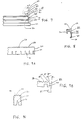
- FIG. 1A is an exploded perspective view of an article for dispensing toner and the like, in accordance with one aspect of the present invention;
- FIG. 1B is an intact perspective view of the article of FIG. 1A;
- FIG. 2 is a side view of the article of FIG. 1A;
- FIG. 3 is an enlarged plan view of the article collar of FIG. 1A;
- FIG. 4 is a side view of an article for dispensing toner and the like, in accordance with another aspect of the present invention;
- FIG. 5A is an enlarged plan view of the article ring of FIG. 1A;
- FIG. 5B is a reverse plan view of the ring of FIG. 5A;
- FIG. 6A is a plan view of a cap for the article, in accordance with one aspect of the present invention;
- FIG. 6B is a sectional view taken along line A-A of FIG. 6A;
- FIG. 7 is a cut-away side view of the article lip and flange portions of FIG. 2 showing the ring of FIG. 5A in phantom;
- FIG. 8 is a sectional view taken along line B-B of FIG. 5A;
- FIG. 9A is an enlarged side view of the ring of FIG. 5A showing the teeth and slot arrangement;
- FIG. 9B is an enlarged cut-away view of the ring of FIG. 9A showing the teeth and hook-like element;
- FIG. 9C is an enlarged cut-away view of a ring slot in accordance with another aspect of the present invention;
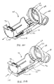
- FIG. 10A is a perspective view of a toner dispensing device in accordance with one aspect of the present invention, the tray being in an extended position;
- FIG. 10B is a perspective view of the toner dispensing device of FIG. 10A, the tray being in an operative position;
- FIG. 11A is a perspective view of a toner dispensing device in accordance with another aspect of the present invention, the tray being in an extended position;
- FIG. 11B is a perspective view of the toner dispensing device of FIG. 11A, the tray being in an operative position;
- FIG. 12A is an exploded perspective view of the device of FIG. 10A;
- FIG. 12B is an exploded perspective view of the device of
- FIG. 11A;
- FIG. 13 is a perspective view of the toner dispensing device of FIG. 10A mounted to a toner storage container;
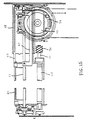
- FIG. 14 is a schematic illustration showing the structure of the toner dispensing device of FIG. 10A and associated apparatus;
- FIG. 15 is a plan view of the structure shown in FIG. 14; and
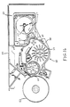
- FIG. 16 is a schematic illustration showing the structure of an electrophotographic copier with a toner dispensing device according to one aspect of the present invention.
- The same numerals are used throughout the various figures of the drawings to designate similar parts.
- Still other objects and advantages of the present invention will become apparent from the following description of the preferred embodiments.
- FIGS. 1A - 16 show generally a specific,
illustrative article 10 for dispensing toner and the like, in accordance with the present invention. The article, e.g., a toner canister, comprises a cylindrical housing 11 with anopen end 12 and aclosed end 13, the open end engaging aflanged collar 14 adjacent thereto. The collar hasteeth 15 extending radially therefrom for operatively engaging aworm gear 74 of atoner dispensing device 40 and, upon such engagement, enabling rotation of the canister. The canister open end further comprises alip 25 andflange portions 20 for snapping engagement with aring 30. - The ring preferably has a plurality of
slots 31, e.g., 36 slots or one for every 10° of ring circumference, as best seen in FIG. 5B. This slot arrangement permits ready expansion of the ring and engagement with the lip and flange portions. Each slot is suitably dimensioned, e.g., from about 0.200 inch to about 0.250 inch long and from about 0.025 inch to about 0.040 inch wide, for ready engagement with the canister. - Alternatively, as shown in FIG. 9C, the slots are tapered, each slot, e.g., being about 0.225 inch long and about 0.025 inch wide, tapering to between about 0.030 and about 0.040 inch. This taper, it has been found, facilitates release of the ring from its mold during manufacture, thereby prolonging mold life. In another alternative embodiment, the plurality of slots comprise selected tapered and untapered configurations. In still another embodiment, no slots are provided in the ring.
- Outwardly facing portions of the ring are preferably tapered, as shown, for instance, in FIG. 9B. A single continuous taper may be used, e.g., within a range of about 1° to about 5°, or two distinct tapered surfaces, e.g., each being within a range of about 1° to about 5° in any combination thereof.
- Axially disposed
teeth 32 are provided about the ring edges 33, preferably about 0.063 inch from the slotupper end 34. The teeth engage a cap-shapedreceptacle 69 oftoner dispensing device 40, limiting ring movement relative thereto while allowing rotation of the canister. This is advantageous since by avoiding rotational and sealing engagement of the canister within and relative to the cap-shaped receptacle, wear and tear ofresilient ring 27 is reduced. Upon the canister's rotation relative to ring 30, toner may be dispensed therefrom. - As best seen in FIG. 7, the lip and flange portions are suitably configured for snapping, loose-fit engagement with
ring 30. For instance, the flanged portions are characterized by at least threeflanges first flange 21 is adjacent the canister open end and has a chamfered leadingedge 24 for sliding reception of the ring, the chamfer being, e.g., about 30° from the vertical axis. In accordance with one aspect of the present invention, the first flange is about 0.155 inch from the canister open end, and measures about 3.375 inches in diameter. The leading edge continues over the canister open end, defininglip 25. - Second flange 22 has a circumference substantially similar to that of the first flange and separated therefrom by a
trough 26, e.g., about 0.091 inch wide. The second flange measures, e.g., about 0.077 inch in width and about 3.375 inches in diameter.Third flange 23 has a relatively larger circumference, e.g., about 3.5 inches in diameter. - Upper and
interior edges 28, 29, respectively, ofring 30 are configured for cooperative engagement with the first and second flanges, the trough, and the lip. As shown in FIGS. 7 and 8,ring 30 comprises a clamp-like fitting 35 having alip 36 for wrapping around and engaginglip 25 of the canister.Portions portion 38 forms a hook-like element 39 which engages the trough, loosely securing the ring to the canister. This loose fit permits the hook-like element to slide freely between the first and second flanges. In this manner, rotation of the canister relative to ring 30 is facilitated. - For transporting the canister, a
shipment ring 80 of a resilient material, e.g., felt, a polymeric material, or the like, may be positioned between the canister open end andring 30, as shown in FIG. 7. This shipment ring, it has been found, hinders the passage of toner between the canister andring 30 during transport, i.e., when the canister may be in unintended orientations for extended periods of time. - Although the present invention is shown and described having a hook and flange configuration for holding the ring on the canister and axially disposed teeth, other configurations may be used, giving consideration to the purpose for which the present invention is intended.
-
Collar 14 is a ring-like piece which fits snugly onto the canister, as shown in FIGS. 1A and 1B. The collar is mounted by simply sliding it over the closed end of the canister and along the canister body. Upon nearing the canister open end, the collar rides up and over aramp 16 formed on the canister housing, snapping into position.Tabs 17 on opposing sides of the canister, upon engagement withsemicircular detents 18 in the third flange, limit rotation of the collar about the canister. The third flange serves as a stop for abutting the collar, i.e., to limit its longitudinal movement along the canister. Upon snapping into position,collar 14 remains permanently affixed to the canister in this embodiment and is not to be removed. Alternatively, as shown in FIG. 4, the collar is formed integrally with the canister and the sides of the canister are tapered, e.g., within a range of about 1° to about 10°. - To store the canister, a
cap 81, as shown in FIGS. 6A and 6B, is preferably mounted at the canister open end, insidering 30. The cap is secured to the canister by snaps 82, 83. Pull-tab 84 allows a user to remove the cap for installation of the canister in a copier. -
Ring 30 andcollar 14 are desirably made of a polymeric material, such as a high impact polystyrene known as "HIPS". Preferably, both the canister and its cap are constructed of polypropylene or the like. The canister may be transparent, translucent, or opaque, giving consideration to the purpose for which the present invention is intended. - Referring now to FIGS. 10A - 16, there is shown a specific, illustrative
toner dispensing device 40 for transporting toner contained in the canister to a developing device or toner storage area of an electrophotographic copier. - Inside
housing 51 of the copier is a developingdevice 52 adjacent aphotosensitive drum 53 on which an electrostatic latent image is developed, as shown in FIG. 16. A developingroller 54 is rotatably supported and disposed adjacent to the drum. An impeller 55 (which is rotatably driven by the developing roller) transports toner to the roller. Thecasing 56 of the developing device has a toner reservoir which temporarily stores fresh toner for supply to the developing roller. - As shown in FIG. 13, an elongated
toner storage container 60 is located adjacent the developing device. Ashaft 61 extends through the container and has anagitator 62 for stirring toner contained therein. Atoner supply roller 63 atsupply port 64 is in communication with the developing device interior and is driven to rotate in accordance with a signal supplied from a toner density detector (not shown). - The toner dispensing device is provided at one end of the storage container and configured to detachably secure a canister for dispensing toner when the device and canister are in an operative position, e.g., about a 1-2° tilt from horizontal. The canister is then rotated in association with the toner supply roller to dispense toner from the container to the developing device.
- Lining (and encircling) the exit from the dispensing device is a
resilient ring 27, e.g., of felt, polymeric foam, or the like. Upon positioning the canister in the device andring 30 in the receptacle, the canister may be rotated readily relative to ring 30 without rotation ofring 30 relative to the receptacle and its resilient ring. This results in minimal wear of the resilient ring. In this connection, the configuration ofring 30 also minimizes spillage of toner during the canister's removal. For instance, toner which cakes about the ring lip falls inside the canister upon its removal rather than onto the dispensing device and into the copier. This substantially eliminates delay from clean-up after changing toner canisters. - On the operative side of the toner storage container, a
cylinder member 65 projects from an end plate 66, and ashaft 61, which extends through the toner storage container, further extends through the cylinder member. As shown in FIGS. 14 and 15, the shaft is provided with a toner transport mechanism such asplate 67 for transporting the toner supplied into the cylinder member through anopening 77 formed in the peripheral wall of the cylinder member, and into the toner storage container. A supportingsleeve 68 is rotatably fit onto the cylinder member. - Integrally provided with the device is cap-shaped
receptacle 69 in which ring 30 may be received. The receptacle is provided with anopening 70 which comes into alignment with the cylinder member opening when the supporting sleeve is rotated relative to the cylinder member so as to locate the receptacle horizontally. Upon such alignment, amouth piece 75 associated with the dispensing device is in proximity to ring 30. The mouth piece is suitably configured for controlling the discharge flow of toner from the canister. - A
canister support arm 41 is secured to the receptacle by suitable fasteners, e.g., screws, the canister being held in position by a tray orholder 42. The holder has abottom plate 47 abutting a bottom central portion 48 of the canister. - At the bottom of the support arm is a
pivotal knob 43. Anintegral pin 44 of the knob projects through an arc-shaped slot 45 formed in the support arm such that the pin is in engagement with an engagingplate 46 integrally provided on the holder. Accordingly, by pivoting the knob, the holder is movable along its longitudinal axis relative to the support arm. - In addition, a
pinion 71 is rotatably supported on the end surface of the toner storage container, and brought into mesh with the collar when the support arm is rotated to a horizontal or operative position. Rotation of the pinion is accomplished through a driving force transmitted fromworm gear 74 which is located at the tip end of the toner supply roller shaft. The roller shaft extends beyond the end wall of the toner storage container through anidler gear 72. The teeth of the collar are brought into mesh with the pinion upon locating the canister in the operative position, e.g., about a 1-2° tilt from the horizontal position. The canister is then rotated synchronously with the toner supply roller to dispense the toner. - To locate the support arm at a position suitable for canister removal, it is rotated counterclockwise around the cylinder member. The knob is then rotated in order to move the holder downward to a lower position designated generally by the two-dotted line, as shown in FIG. 14. The canister received in the holder may then be pulled out of the receptacle and removed from the holder. After the canister has been recharged or a new canister obtained, it is inserted into the holder such that the canister open end fits into the receptacle. When the knob is rotated back to its original position, the canister is locked in position.
- Then, the support arm is rotated clockwise over 90° to bring
magnet 73 into contact with a magneticallyattractable element 78 mounted to the housing. This permits the support arm and thus the canister to be held relatively horizontally. When so located, the collar teeth are brought into mesh with the pinion and, moreover, the opening of the cap-shaped receptacle comes into alignment with the opening of the cylinder member. This allows toner in the canister to be supplied through the cylinder member and into the storage container. - In accordance with one aspect of the present invention, upon securing the canister in the holder, a
gap 76 is formed between the holder bottom and the canister engaging portion of the device. This gap receives the collar of the canister and allows its unobstructed rotation. - Upon repeated photocopy operations, toner density within the developing device decreases. When a toner density detector (not shown) senses this decrease, an electromagnetic clutch (also not shown) is signaled to begin rotation of the toner supply roller on the shaft. In association therewith, the worm gear (also mounted on the shaft) begins rotating which, in turn, causes the canister to rotate to dispense toner through the aligned openings, and into the cylinder member.
Toner transport plate 67 then transports the toner further, into the storage container. This process continues until the toner supply roller stops, i.e., when the toner density within the developing device reaches a predetermined value. - Although the canister and dispensing device are shown and described at a selected inclination, e.g., a 1-2° tilt, it will be appreciated that their orientation and the manner of their movement may be varied depending upon flow properties of the toner and/or other factors. Also, while the canister illustrated is generally cylindrical in shape, it will be understood that other canister configurations and/or geometries may be appropriate, giving consideration to the purpose for which the present invention is intended.
- Since from the foregoing the construction and advantages of the invention may be readily understood, further explanation is believed unnecessary. However, since numerous modifications will readily occur to those skilled in the art after consideration of the foregoing specification and accompanying drawings, it is not intended that the invention be limited to the exact construction shown and described, but all suitable modifications and equivalents may be resorted to which fall within the scope of the appended claims.
Claims (14)
- An article for dispensing toner and the like to an electrophotographic copier, the article comprising a generally cylindrical housing with an open end and a closed end, the open end having a flanged collar adjacent thereto, the collar having outwardly extending teeth for enabling the article's rotation upon driving engagement with a dispensing device of the copier, the article open end further comprising a lip and flange portions which loosely secure a ring thereto, the ring having edges configured for engaging a receptacle of the dispensing device so as to limit ring movement relative to the receptacle, while allowing rotation of the canister, the ring also having lip portions configured for minimizing spillage of toner upon removal of the canister from the receptacle.
- The article set forth in claim 1 wherein the ring edges are serrated so as to limit ring movement upon engagement with the receptacle.
- The article set forth in claim 1 wherein the flange portions comprise at least two flanges defining a trough therebetween.
- The article set forth in claim 3 wherein the ring further includes a hook-like member for engaging the trough and retaining the ring on the article.
- The article set forth in claim 1 wherein the ring further includes a plurality of slots about the circumference thereof.
- The article set forth in claim 5 wherein each slot has a selected taper.
- A method of dispensing toner and the like to an electrophotographic copier, the method comprising the steps of:providing an article having a generally cylindrical housing with an open end and a closed end, the open end having a flanged collar adjacent thereto, the collar including outwardly extending teeth for enabling rotation of the article upon driving engagement with a dispensing device of the copier, the housing containing a selected volume of toner;providing a ring in engagement with the open end of the housing, the article open end further comprising a lip and flange portions configured for loosely securing the ring thereto, the ring having serrated edges in engagement with a receptacle of the dispensing device and limiting movement of the ring relative to the receptacle, while allowing rotation of the canister, the ring also having lip portions configured for minimizing spillage of toner upon removal of the canister from the receptacle;rotating the housing so as to dispense the selected volume of toner; andupon delivering substantially the selected volume of toner to the copier, removing the housing from the receptacle.
- The method set forth in claim 7 wherein a storage cap is removed from the article open end prior to engagement with the receptacle.
- In combination, a toner dispensing device and article for dispensing toner to an electrophotographic copier, the article comprising a generally cylindrical housing with an open end and a closed end, the open end having a flanged collar adjacent thereto, the collar having outwardly extending teeth for enabling the article's rotation upon driving engagement with a dispensing device of the copier, the article open end further comprising a lip and flange portions which loosely secure a ring thereto, the ring having edges configured for engaging a receptacle of the dispensing device so as to limit ring movement relative to the receptacle, while allowing rotation of the canister, the ring also having lip portions configured for minimizing spillage of toner upon removal of the canister from the receptacle.
- The article set forth in claim 9 wherein the ring edges are serrated so as to limit ring movement upon engagement with the receptacle.
- The article set forth in claim 9 wherein the flange portions comprise at least two flanges defining a trough therebetween.
- The article set forth in claim 11 wherein the ring further includes a hook-like member for engaging the trough and retaining the ring on the article.
- The article set forth in claim 9 wherein the ring further includes a plurality of slots about the circumference thereof.
- The article set forth in claim 13 wherein each slot has a selected taper.
Applications Claiming Priority (2)
| Application Number | Priority Date | Filing Date | Title |
|---|---|---|---|
| US48176495A | 1995-06-07 | 1995-06-07 | |
| US481764 | 1995-06-07 |
Publications (3)
| Publication Number | Publication Date |
|---|---|
| EP0747784A2 true EP0747784A2 (en) | 1996-12-11 |
| EP0747784A3 EP0747784A3 (en) | 1997-10-29 |
| EP0747784B1 EP0747784B1 (en) | 1999-09-22 |
Family
ID=23913300
Family Applications (1)
| Application Number | Title | Priority Date | Filing Date |
|---|---|---|---|
| EP96830335A Expired - Lifetime EP0747784B1 (en) | 1995-06-07 | 1996-06-07 | Article and method for dispensing toner and the like |
Country Status (4)
| Country | Link |
|---|---|
| US (1) | US5669044A (en) |
| EP (1) | EP0747784B1 (en) |
| AT (1) | ATE185002T1 (en) |
| DE (1) | DE69604334D1 (en) |
Families Citing this family (16)
| Publication number | Priority date | Publication date | Assignee | Title |
|---|---|---|---|---|
| JPH10213959A (en) * | 1997-01-30 | 1998-08-11 | Konica Corp | Developer replenishment device and image forming device |
| US6968139B2 (en) * | 1997-06-19 | 2005-11-22 | Canon Kabushiki Kaisha | Toner supply container and electrophotographic image forming apparatus |
| JP3408153B2 (en) * | 1997-06-19 | 2003-05-19 | キヤノン株式会社 | Toner supply container and electrophotographic image forming apparatus |
| JP3697065B2 (en) | 1997-06-19 | 2005-09-21 | キヤノン株式会社 | Toner supply container and electrophotographic image forming apparatus |
| JP3408166B2 (en) * | 1997-09-30 | 2003-05-19 | キヤノン株式会社 | Toner supply container and electrophotographic image forming apparatus |
| EP0926572B1 (en) * | 1997-12-24 | 2004-04-21 | Konica Corporation | Developer replenishing apparatus |
| US5991584A (en) * | 1998-10-07 | 1999-11-23 | Katun Coporation | Toner cartridge assembly |
| JP3445202B2 (en) | 1999-03-29 | 2003-09-08 | キヤノン株式会社 | Toner supply container |
| US6396408B2 (en) * | 2000-03-31 | 2002-05-28 | Donnelly Corporation | Digital electrochromic circuit with a vehicle network |
| US6243554B1 (en) * | 2000-07-28 | 2001-06-05 | General Plastic Industrial Co., Ltd | Developer replenishing container |
| JP4376851B2 (en) * | 2005-10-07 | 2009-12-02 | シャープ株式会社 | Developer supply device |
| JP4376853B2 (en) * | 2005-10-07 | 2009-12-02 | シャープ株式会社 | Developer supply device |
| JP4376852B2 (en) * | 2005-10-07 | 2009-12-02 | シャープ株式会社 | Developer supply device |
| US7729644B2 (en) * | 2006-05-11 | 2010-06-01 | Katun Corporation | Toner cartridge |
| JP6524953B2 (en) | 2016-04-07 | 2019-06-05 | 京セラドキュメントソリューションズ株式会社 | Toner container and image forming apparatus |
| US11466735B2 (en) | 2020-03-13 | 2022-10-11 | Rolls-Royce Corporation | Electromagnetic clutch system |
Citations (4)
| Publication number | Priority date | Publication date | Assignee | Title |
|---|---|---|---|---|
| US3526341A (en) * | 1967-09-20 | 1970-09-01 | Stromberg Carlson Corp | Powder dispenser and canister |
| US3853246A (en) * | 1974-02-15 | 1974-12-10 | Pitney Bowes Inc | Disposable dispenser |
| US4611730A (en) * | 1984-01-09 | 1986-09-16 | Ricoh Company, Ltd. | Toner replenishing device |
| EP0616268A1 (en) * | 1993-03-14 | 1994-09-21 | Ricoh Company, Ltd | Toner container and toner replenishing device |
Family Cites Families (90)
| Publication number | Priority date | Publication date | Assignee | Title |
|---|---|---|---|---|
| US143323A (en) * | 1873-09-30 | Improvement in feeding devices for coal and ore separators | ||
| US604937A (en) * | 1898-05-31 | Bin for powdered material | ||
| US753729A (en) * | 1903-08-01 | 1904-03-01 | American Seeding Machine Co | Seeding attachment for corn-planters. |
| GB191102833A (en) * | 1911-02-03 | 1911-05-25 | Karl Soos | Improvements in Freezers for Confectioners' Use. |
| US1485222A (en) * | 1922-08-18 | 1924-02-26 | Charles L Cinty | Spraying apparatus |
| US1822557A (en) * | 1928-08-16 | 1931-09-08 | Beatton Rowland Sutton | Dispensing apparatus |
| US1964176A (en) * | 1929-06-25 | 1934-06-26 | Root Mfg Company | Dusting machine |
| US2100216A (en) * | 1936-06-10 | 1937-11-23 | Philip C Hughes | Vending machine |
| US2337161A (en) * | 1941-10-03 | 1943-12-21 | Raymond M Hessert | Ice cream dispensing and packing device |
| US2394453A (en) * | 1941-12-29 | 1946-02-05 | Kalman Z Huszar | Rod mill |
| US2367585A (en) * | 1941-12-29 | 1945-01-16 | Kalman Z Huszar | Rod mill |
| US2392245A (en) * | 1941-12-29 | 1946-01-01 | Kalman Z Huszar | Rod mill |
| US2436959A (en) * | 1946-06-17 | 1948-03-02 | Galion Metallic Vault Co | Vehicle transporting means |
| US2534782A (en) * | 1947-09-16 | 1950-12-19 | Duanc C Maddux | Dispensing machine for ice cream and sherbets |
| US2720340A (en) * | 1953-01-22 | 1955-10-11 | August W Gustafson | Fertilizer distributor |
| US2722357A (en) * | 1953-06-05 | 1955-11-01 | Smith Kline French Lab | Mixing and dispensing apparatus |
| US2965266A (en) * | 1958-04-30 | 1960-12-20 | Haloid Xerox Inc | Xerographic toner dispenser |
| US3147956A (en) * | 1961-04-04 | 1964-09-08 | Charles E Phillips | Machine for mixing particulate materials |
| US3122277A (en) * | 1962-01-23 | 1964-02-25 | Sperry Rand Corp | Hopper combined with elongated container in a stock feeder |
| US3259372A (en) * | 1964-01-27 | 1966-07-05 | Charles E Phillips | Blending and mixing apparatus |
| US3269707A (en) * | 1964-01-27 | 1966-08-30 | Charles E Phillips | Particulate material mixing machine |
| US3325844A (en) * | 1964-07-27 | 1967-06-20 | Electrolux Corp | End closure arrangement for dispensing foamable liquids |
| US3589568A (en) * | 1969-04-17 | 1971-06-29 | Ppg Industries Inc | Rotatable hollow shaft, helix, and drum for feeding solids |
| US3703360A (en) * | 1970-08-21 | 1972-11-21 | Ethyl Corp | Gasoline additive and composition |
| US3647293A (en) * | 1970-12-01 | 1972-03-07 | Ibm | Copying system featuring combined developing-cleaning station alternately activated |
| US3722471A (en) * | 1970-12-23 | 1973-03-27 | J Stoffel | Toner meter device |
| US3764208A (en) * | 1970-12-29 | 1973-10-09 | Canon Kk | Developing device for use in electrophotographic copying machines |
| US3724725A (en) * | 1971-03-30 | 1973-04-03 | Ibm | Electroscopic powder feeding apparatus utilizing rotating helical members |
| JPS5627873B1 (en) * | 1971-05-10 | 1981-06-27 | ||
| NL168188C (en) * | 1971-05-25 | 1982-03-16 | Oce Van Der Grinten Nv | SYSTEM FOR DELIVERING FINE GRANULAR POWDER. |
| US3712266A (en) * | 1971-08-20 | 1973-01-23 | Ibm | Developer conveying apparatus |
| US3700142A (en) * | 1971-09-20 | 1972-10-24 | Singer Co | Powder dispensing unit |
| US4034701A (en) * | 1972-06-28 | 1977-07-12 | Xerox Corporation | Particle dispenser |
| US3829066A (en) * | 1973-04-04 | 1974-08-13 | C Phillips | Particulate material mixing machine |
| SE393465B (en) * | 1973-06-28 | 1977-05-09 | Oce Van Der Grinten Nv | KIT AND DEVICE FOR DEVELOPING AN ELECTROSTATIC CHARGING SAMPLE |
| US3915208A (en) * | 1973-07-24 | 1975-10-28 | Inforex | Toner supply apparatus with replenishing container |
| US3901411A (en) * | 1973-11-19 | 1975-08-26 | John F Bauman | Apparatus for dispensing pavement sealer material |
| US3915340A (en) * | 1974-03-19 | 1975-10-28 | Pitney Bowes Inc | Indicator for a dispensing device |
| JPS5928908B2 (en) * | 1974-07-27 | 1984-07-17 | キヤノン株式会社 | developing device |
| SU558253A1 (en) * | 1974-08-13 | 1977-05-15 | Научно-Исследовательский Институт Электрографии | Device for transporting ferromagnetic powder |
| US3979026A (en) * | 1974-09-16 | 1976-09-07 | Roger Howard Lee | Apparatus for dispensing particulate and viscous liquid material |
| US4062385A (en) * | 1975-03-14 | 1977-12-13 | Eastman Kodak Company | Toner handling apparatus |
| JPS5219232U (en) * | 1975-07-30 | 1977-02-10 | ||
| US4060105A (en) * | 1975-09-11 | 1977-11-29 | Xerox Corporation | Toner loading apparatus with replenishing supply container |
| US3999514A (en) * | 1975-09-29 | 1976-12-28 | International Business Machines Corporation | Magnetic brush developer |
| US4026336A (en) * | 1975-11-24 | 1977-05-31 | Spies Henry J | Dispensing apparatus |
| US4062476A (en) * | 1975-12-04 | 1977-12-13 | Marvin Glass & Associates | Ice dispenser with rotatable supply container |
| IT1057196B (en) * | 1976-02-16 | 1982-03-10 | Olivetti C E C S P A | CARTRIDGE FOR THE SUPPLY OF THE DEVELOPMENT POWDER IN A COPIER MACHINE |
| JPS52130643A (en) * | 1976-04-27 | 1977-11-02 | Canon Inc | Developing device |
| JPS52138138A (en) * | 1976-05-14 | 1977-11-18 | Canon Inc | Device for transporting developer for electro photography |
| US4018187A (en) * | 1976-06-30 | 1977-04-19 | International Business Machines Corporation | Grooved magnetic brush roll |
| SE404911B (en) * | 1977-03-21 | 1978-11-06 | Boliden Ab | METHODS AND APPARATUS FOR OPENING AND EMPTYING THE CONTENTS OF PACKAGING DISHES OR SUITABLE FOR VEHICLES, GRAIN AND POWDERED AND GOODS WITHOUT POLLUTING OR DUSTING THE ENVIRONMENT |
| GB1559252A (en) | 1977-04-14 | 1980-01-16 | Rex Rotary International | Supply of toner powder in a developer for an electrostatographic copier |
| US4133458A (en) * | 1977-05-02 | 1979-01-09 | Xerox Corporation | Toner dispenser arrangement |
| DE2723805C3 (en) * | 1977-05-26 | 1980-07-03 | Canon K.K., Tokio | Refill device for toner powder in an electrophotographic copier |
| US4173239A (en) * | 1977-07-12 | 1979-11-06 | Chicago Bridge & Iron Company | Method of and apparatus for controlling the flow of materials from a rotating drum |
| JPS5439639A (en) * | 1977-09-05 | 1979-03-27 | Canon Inc | Conveying device of powder developer |
| JPS5459152A (en) * | 1977-10-20 | 1979-05-12 | Konishiroku Photo Ind Co Ltd | Toner container having constant feed function |
| US4161923A (en) * | 1977-12-22 | 1979-07-24 | International Business Machines Corporation | Electrophotographic developer with carrier overflow control |
| JPS54116932A (en) * | 1978-03-03 | 1979-09-11 | Ricoh Co Ltd | Powder toner conveyor |
| US4164306A (en) * | 1978-04-03 | 1979-08-14 | Towlsaver, Inc. | Soap dispenser including removable soap supply container positioner and stabilizer |
| JPS54136337A (en) * | 1978-04-14 | 1979-10-23 | Fujitsu Ltd | Toner feeder |
| DE2834508C2 (en) * | 1978-08-07 | 1986-04-03 | Olympia Werke Ag, 2940 Wilhelmshaven | Electrophotographic copier with a photoconductive layer on a drum or on a belt |
| JPS5596966A (en) * | 1979-01-17 | 1980-07-23 | Hitachi Metals Ltd | Toner cartridge |
| JPS55111978A (en) * | 1979-02-20 | 1980-08-29 | Canon Inc | Image forming device |
| DE3009471C2 (en) * | 1979-03-15 | 1982-04-29 | Tokyo Shibaura Denki K.K., Kawasaki, Kanagawa | Developer transport device for electrostatic copiers |
| JPS5640866A (en) * | 1979-09-11 | 1981-04-17 | Matsushita Graphic Commun Syst Inc | Toner supplying device |
| JPS5648660A (en) * | 1979-09-27 | 1981-05-01 | Matsushita Electric Ind Co Ltd | Toner replenishing device |
| US4304273A (en) * | 1979-12-31 | 1981-12-08 | International Business Machines Corporation | Toner container and toner dispensing apparatus |
| JPS56147462A (en) * | 1980-04-17 | 1981-11-16 | Fujitsu Ltd | Laser trimming method for resistor film |
| US4342282A (en) * | 1980-05-07 | 1982-08-03 | Hitachi Metals, Ltd. | Toner cartridge |
| DE3116870C1 (en) * | 1981-04-28 | 1982-10-28 | Siemens AG, 1000 Berlin und 8000 München | Device for filling toner from a container into a storage container |
| JPS5897068A (en) * | 1981-12-03 | 1983-06-09 | Minolta Camera Co Ltd | Developer supplementing device |
| US4615364A (en) * | 1982-06-23 | 1986-10-07 | Konishiroku Photo Industry Co., Ltd. | Developer incoming device in electrostatic reproducing apparatus |
| JPS5912465A (en) * | 1982-07-13 | 1984-01-23 | Canon Inc | Developing device |
| JPS5912464A (en) * | 1982-07-13 | 1984-01-23 | Canon Inc | Developing device |
| JPS5915954A (en) * | 1982-07-19 | 1984-01-27 | Canon Inc | Developing device |
| JPS59188678A (en) * | 1983-04-09 | 1984-10-26 | Ricoh Co Ltd | Toner replenishing device of dry type copying machine |
| US4878603B1 (en) * | 1984-01-09 | 1994-11-08 | Ricoh Kk | Toner replenishing device |
| US4561567A (en) * | 1984-01-20 | 1985-12-31 | Pitney Bowes Inc. | Toner loading apparatus |
| JPS6151177A (en) * | 1984-08-20 | 1986-03-13 | Ricoh Co Ltd | Toner storage vessel |
| US4603714A (en) * | 1985-03-18 | 1986-08-05 | Xerox Corporation | Toner bottle for copier/printing machines |
| US4739907A (en) * | 1987-04-27 | 1988-04-26 | Xerox Corporation | Developer storage and dispenser apparatus |
| JPH0561347A (en) * | 1991-08-30 | 1993-03-12 | Ricoh Co Ltd | Toner replenishing device for image forming device |
| JPH0643754A (en) * | 1992-07-26 | 1994-02-18 | Ricoh Co Ltd | Toner container |
| JP3243697B2 (en) * | 1992-07-26 | 2002-01-07 | 株式会社リコー | Toner supply device |
| US5259534A (en) * | 1992-08-28 | 1993-11-09 | National Packaging | Container cap with removable insert |
| TW240299B (en) * | 1992-12-30 | 1995-02-11 | Ricoh Kk | |
| JP3236107B2 (en) * | 1993-03-19 | 2001-12-10 | 株式会社リコー | Toner supply device |
| US5516143A (en) * | 1994-06-20 | 1996-05-14 | Morton International, Inc. | Windowed airbag cover |
-
1996
- 1996-06-07 AT AT96830335T patent/ATE185002T1/en not_active IP Right Cessation
- 1996-06-07 EP EP96830335A patent/EP0747784B1/en not_active Expired - Lifetime
- 1996-06-07 DE DE69604334T patent/DE69604334D1/en not_active Expired - Lifetime
-
1997
- 1997-01-21 US US08/786,413 patent/US5669044A/en not_active Expired - Fee Related
Patent Citations (5)
| Publication number | Priority date | Publication date | Assignee | Title |
|---|---|---|---|---|
| US3526341A (en) * | 1967-09-20 | 1970-09-01 | Stromberg Carlson Corp | Powder dispenser and canister |
| US3853246A (en) * | 1974-02-15 | 1974-12-10 | Pitney Bowes Inc | Disposable dispenser |
| US4611730A (en) * | 1984-01-09 | 1986-09-16 | Ricoh Company, Ltd. | Toner replenishing device |
| US4611730B1 (en) * | 1984-01-09 | 1994-11-08 | Ricoh Kk | Toner replenishing device |
| EP0616268A1 (en) * | 1993-03-14 | 1994-09-21 | Ricoh Company, Ltd | Toner container and toner replenishing device |
Also Published As
| Publication number | Publication date |
|---|---|
| EP0747784B1 (en) | 1999-09-22 |
| DE69604334D1 (en) | 1999-10-28 |
| EP0747784A3 (en) | 1997-10-29 |
| US5669044A (en) | 1997-09-16 |
| ATE185002T1 (en) | 1999-10-15 |
Similar Documents
| Publication | Publication Date | Title |
|---|---|---|
| US5669044A (en) | Article and method for dispensing toner and the like | |
| EP0999480B1 (en) | Developer container | |
| US5441177A (en) | Toner container and toner replenishing device including a cap member having a shutter | |
| US4611730A (en) | Toner replenishing device | |
| EP0032986A2 (en) | Toner transfer facilitation apparatus | |
| US6097903A (en) | Toner supplying device, toner container therefor and image forming apparatus using same toner supplying device and toner container | |
| US5385181A (en) | Dispensing cartridge | |
| JP2001228692A (en) | Toner replenishing device for image forming device and toner cartridge used therein | |
| JPH0759432B2 (en) | Powder distribution cartridge | |
| US4561567A (en) | Toner loading apparatus | |
| JP3224801B2 (en) | Toner supply device | |
| US6144828A (en) | Toner reservoir for use in electrostatic image generating apparatus | |
| JP2562125B2 (en) | Toner cartridge | |
| EP0740219A2 (en) | Developing unit and toner cartridge | |
| JPH081531B2 (en) | Toner cartridge | |
| JPH0452951B2 (en) |
Legal Events
| Date | Code | Title | Description |
|---|---|---|---|
| PUAI | Public reference made under article 153(3) epc to a published international application that has entered the european phase |
Free format text: ORIGINAL CODE: 0009012 |
|
| AK | Designated contracting states |
Kind code of ref document: A2 Designated state(s): AT BE CH DE DK ES FI FR GB GR IE IT LI LU MC NL PT SE |
|
| AX | Request for extension of the european patent |
Free format text: LT;LV;SI |
|
| PUAL | Search report despatched |
Free format text: ORIGINAL CODE: 0009013 |
|
| AK | Designated contracting states |
Kind code of ref document: A3 Designated state(s): AT BE CH DE DK ES FI FR GB GR IE IT LI LU MC NL PT SE |
|
| AX | Request for extension of the european patent |
Free format text: LT;LV;SI |
|
| 17P | Request for examination filed |
Effective date: 19980129 |
|
| 17Q | First examination report despatched |
Effective date: 19980227 |
|
| GRAG | Despatch of communication of intention to grant |
Free format text: ORIGINAL CODE: EPIDOS AGRA |
|
| GRAG | Despatch of communication of intention to grant |
Free format text: ORIGINAL CODE: EPIDOS AGRA |
|
| GRAH | Despatch of communication of intention to grant a patent |
Free format text: ORIGINAL CODE: EPIDOS IGRA |
|
| GRAH | Despatch of communication of intention to grant a patent |
Free format text: ORIGINAL CODE: EPIDOS IGRA |
|
| GRAA | (expected) grant |
Free format text: ORIGINAL CODE: 0009210 |
|
| AK | Designated contracting states |
Kind code of ref document: B1 Designated state(s): AT BE CH DE DK ES FI FR GB GR IE IT LI LU MC NL PT SE |
|
| PG25 | Lapsed in a contracting state [announced via postgrant information from national office to epo] |
Ref country code: SE Free format text: THE PATENT HAS BEEN ANNULLED BY A DECISION OF A NATIONAL AUTHORITY Effective date: 19990922 Ref country code: NL Free format text: LAPSE BECAUSE OF FAILURE TO SUBMIT A TRANSLATION OF THE DESCRIPTION OR TO PAY THE FEE WITHIN THE PRESCRIBED TIME-LIMIT Effective date: 19990922 Ref country code: LI Free format text: LAPSE BECAUSE OF FAILURE TO SUBMIT A TRANSLATION OF THE DESCRIPTION OR TO PAY THE FEE WITHIN THE PRESCRIBED TIME-LIMIT Effective date: 19990922 Ref country code: IT Free format text: LAPSE BECAUSE OF FAILURE TO SUBMIT A TRANSLATION OF THE DESCRIPTION OR TO PAY THE FEE WITHIN THE PRE;WARNING: LAPSES OF ITALIAN PATENTS WITH EFFECTIVE DATE BEFORE 2007 MAY HAVE OCCURRED AT ANY TIME BEFORE 2007. THE CORRECT EFFECTIVE DATE MAY BE DIFFERENT FROM THE ONE RECORDED.SCRIBED TIME-LIMIT Effective date: 19990922 Ref country code: GR Free format text: LAPSE BECAUSE OF NON-PAYMENT OF DUE FEES Effective date: 19990922 Ref country code: FR Free format text: LAPSE BECAUSE OF FAILURE TO SUBMIT A TRANSLATION OF THE DESCRIPTION OR TO PAY THE FEE WITHIN THE PRESCRIBED TIME-LIMIT Effective date: 19990922 Ref country code: FI Free format text: LAPSE BECAUSE OF NON-PAYMENT OF DUE FEES Effective date: 19990922 Ref country code: ES Free format text: THE PATENT HAS BEEN ANNULLED BY A DECISION OF A NATIONAL AUTHORITY Effective date: 19990922 Ref country code: CH Free format text: LAPSE BECAUSE OF FAILURE TO SUBMIT A TRANSLATION OF THE DESCRIPTION OR TO PAY THE FEE WITHIN THE PRESCRIBED TIME-LIMIT Effective date: 19990922 Ref country code: BE Free format text: LAPSE BECAUSE OF FAILURE TO SUBMIT A TRANSLATION OF THE DESCRIPTION OR TO PAY THE FEE WITHIN THE PRESCRIBED TIME-LIMIT Effective date: 19990922 Ref country code: AT Free format text: LAPSE BECAUSE OF FAILURE TO SUBMIT A TRANSLATION OF THE DESCRIPTION OR TO PAY THE FEE WITHIN THE PRESCRIBED TIME-LIMIT Effective date: 19990922 |
|
| REF | Corresponds to: |
Ref document number: 185002 Country of ref document: AT Date of ref document: 19991015 Kind code of ref document: T |
|
| REG | Reference to a national code |
Ref country code: CH Ref legal event code: EP |
|
| REF | Corresponds to: |
Ref document number: 69604334 Country of ref document: DE Date of ref document: 19991028 |
|
| REG | Reference to a national code |
Ref country code: IE Ref legal event code: FG4D |
|
| PG25 | Lapsed in a contracting state [announced via postgrant information from national office to epo] |
Ref country code: PT Free format text: LAPSE BECAUSE OF FAILURE TO SUBMIT A TRANSLATION OF THE DESCRIPTION OR TO PAY THE FEE WITHIN THE PRESCRIBED TIME-LIMIT Effective date: 19991222 Ref country code: DK Free format text: LAPSE BECAUSE OF FAILURE TO SUBMIT A TRANSLATION OF THE DESCRIPTION OR TO PAY THE FEE WITHIN THE PRESCRIBED TIME-LIMIT Effective date: 19991222 |
|
| PG25 | Lapsed in a contracting state [announced via postgrant information from national office to epo] |
Ref country code: DE Free format text: LAPSE BECAUSE OF FAILURE TO SUBMIT A TRANSLATION OF THE DESCRIPTION OR TO PAY THE FEE WITHIN THE PRESCRIBED TIME-LIMIT Effective date: 19991223 |
|
| EN | Fr: translation not filed | ||
| NLV1 | Nl: lapsed or annulled due to failure to fulfill the requirements of art. 29p and 29m of the patents act | ||
| REG | Reference to a national code |
Ref country code: CH Ref legal event code: PL |
|
| PG25 | Lapsed in a contracting state [announced via postgrant information from national office to epo] |
Ref country code: LU Free format text: LAPSE BECAUSE OF NON-PAYMENT OF DUE FEES Effective date: 20000607 Ref country code: IE Free format text: LAPSE BECAUSE OF NON-PAYMENT OF DUE FEES Effective date: 20000607 Ref country code: GB Free format text: LAPSE BECAUSE OF NON-PAYMENT OF DUE FEES Effective date: 20000607 |
|
| PG25 | Lapsed in a contracting state [announced via postgrant information from national office to epo] |
Ref country code: MC Free format text: THE PATENT HAS BEEN ANNULLED BY A DECISION OF A NATIONAL AUTHORITY Effective date: 20000630 |
|
| PLBE | No opposition filed within time limit |
Free format text: ORIGINAL CODE: 0009261 |
|
| STAA | Information on the status of an ep patent application or granted ep patent |
Free format text: STATUS: NO OPPOSITION FILED WITHIN TIME LIMIT |
|
| 26N | No opposition filed | ||
| GBPC | Gb: european patent ceased through non-payment of renewal fee |
Effective date: 20000607 |
|
| REG | Reference to a national code |
Ref country code: IE Ref legal event code: MM4A |