EP0747653A1 - Gegenstand ein erstes Element umfassend, eine Stange die relativ zu diesen ersten Element gleiten kann, und eine Verriegelungsvorrichtung - Google Patents
Gegenstand ein erstes Element umfassend, eine Stange die relativ zu diesen ersten Element gleiten kann, und eine Verriegelungsvorrichtung Download PDFInfo
- Publication number
- EP0747653A1 EP0747653A1 EP95401101A EP95401101A EP0747653A1 EP 0747653 A1 EP0747653 A1 EP 0747653A1 EP 95401101 A EP95401101 A EP 95401101A EP 95401101 A EP95401101 A EP 95401101A EP 0747653 A1 EP0747653 A1 EP 0747653A1
- Authority
- EP
- European Patent Office
- Prior art keywords
- rod
- assembly according
- assembly
- tongue
- recess
- Prior art date
- Legal status (The legal status is an assumption and is not a legal conclusion. Google has not performed a legal analysis and makes no representation as to the accuracy of the status listed.)
- Granted
Links
Images

Classifications
-
- F—MECHANICAL ENGINEERING; LIGHTING; HEATING; WEAPONS; BLASTING
- F16—ENGINEERING ELEMENTS AND UNITS; GENERAL MEASURES FOR PRODUCING AND MAINTAINING EFFECTIVE FUNCTIONING OF MACHINES OR INSTALLATIONS; THERMAL INSULATION IN GENERAL
- F16B—DEVICES FOR FASTENING OR SECURING CONSTRUCTIONAL ELEMENTS OR MACHINE PARTS TOGETHER, e.g. NAILS, BOLTS, CIRCLIPS, CLAMPS, CLIPS OR WEDGES; JOINTS OR JOINTING
- F16B21/00—Means for preventing relative axial movement of a pin, spigot, shaft or the like and a member surrounding it; Stud-and-socket releasable fastenings
- F16B21/10—Means for preventing relative axial movement of a pin, spigot, shaft or the like and a member surrounding it; Stud-and-socket releasable fastenings by separate parts
- F16B21/16—Means for preventing relative axial movement of a pin, spigot, shaft or the like and a member surrounding it; Stud-and-socket releasable fastenings by separate parts with grooves or notches in the pin or shaft
-
- F—MECHANICAL ENGINEERING; LIGHTING; HEATING; WEAPONS; BLASTING
- F41—WEAPONS
- F41A—FUNCTIONAL FEATURES OR DETAILS COMMON TO BOTH SMALLARMS AND ORDNANCE, e.g. CANNONS; MOUNTINGS FOR SMALLARMS OR ORDNANCE
- F41A25/00—Gun mountings permitting recoil or return to battery, e.g. gun cradles; Barrel buffers or brakes
- F41A25/26—Assembling or dismounting recoil elements or systems
Definitions
- the invention relates to an assembly comprising an element, a rod movable in axial translation relative to this element, and a removable blocking part.
- the invention relates in particular to the brake rods or to a weapon recuperator, in particular of an artillery piece.
- a device in particular in which a half-shell flange can be screwed to a lateral face of the cylinder head sleeve in order to trap a stud secured to the brake rod.
- a system of adhesives makes it possible to engage the end of the rod in an orifice of the sleeve and to block the rod in translation by a rotation of a quarter of a turn around its axis.
- this device is difficult to machine and therefore expensive, especially if the rod is engaged deep inside the sleeve.
- the invention therefore relates to an assembly comprising an element, a rod movable in axial translation relative to this element, and a removable blocking part arranged to be associated with the element in a first position in which it is in the trajectory d 'a portion of the periphery of the rod and prohibits its relative translation.
- this assembly is characterized in that it is arranged so that, as soon as the blocking piece occupies the first position, support the blocking piece and prevent its movement under the action of the rod or of the element .
- the rod is therefore immobilized as soon as the locking piece is installed in the first position. It is therefore not necessary, once the locking piece in place, to use specific fixing means to immobilize it, which could complicate the machining or increase the assembly and disassembly times.
- This set is perfectly suited to all devices requiring removable attachment to a element of a sliding rod.
- it can be advantageously used for all configurations of brake rods or recuperator, including in common cases of assembly by the rear or side faces of the sleeve.
- it is particularly suitable for cases of brake rods engaging deeply in the sleeve.
- the assembly is arranged to guide the blocking part with respect to the element between the first position and a second position in which the blocking part can be easily installed or removed by the user. .
- the guide of the part takes place in a plane substantially orthogonal to the axis of the rod.
- the guide is a guide in translation.
- the element comprises a recess allowing the workpiece to be guided between the first and second positions.
- the invention also relates to a weapon, in particular an artillery piece, comprising an assembly according to the invention.
- the assembly includes an element 1 which is here the breech sleeve of the weapon, and a rod 2 of axis 8 movable in axial translation relative to this sleeve 1.
- the rod 2 is a brake rod of the weapon , this brake being produced here by means of a jack 3 as is well known.
- the rod 2 is therefore the rod of the jack 3.
- the rod 2 could also be the rod of a conventional recuperator.
- the assembly also includes a removable blocking piece 4 arranged to be associated with the sleeve 1 in a first position.
- the blocking piece 4 In this first position 6 shown in FIG. 3, the blocking piece 4 is in the path of a portion 5 of the periphery of the rod 2 and prohibits its translation relative to the sleeve 1.
- the rod 2 is partly movable inside the sleeve 1 in the cylindrical conduit 50 coaxial with the rod 2.
- the portion 5 is located inside the sleeve 1 when the blocking piece 4 occupies the first position 6.
- the locking piece 4 is also located substantially inside the sleeve 1.
- the assembly is arranged so that, as soon as the locking piece 4 occupies the first position 6, support the locking piece 4 and prevent its movement under the action of the rod 2 or of the sleeve 1.
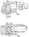
- the assembly is here arranged to guide the locking piece 4 relative to the sleeve between the first position 6 and a second position 7, shown in FIG. 2, in which the locking piece 4 can be easily installed or removed. by the user.
- the guiding of the part 4 takes place in a plane 10 substantially orthogonal to the axis 8 of the rod 2.
- the trace of the plane 10 is visible in FIG. 2 whose cutting plane is orthogonal to this plane 10.
- the guide here is a guide in translation.
- the sleeve 1 includes a tubular recess 12 for guiding the part 4 between the first 6 and second 7 positions.
- the axis 13 of this recess is orthogonal to the axis 8 of the rod 2 and here horizontal. In position 7, the part 4 partially protrudes outside the sleeve.
- the part 4 comprises a tubular part 14 arranged to allow the part 4 to slide in the recess 12.
- the recess 12 and the tubular part 14 are here cylindrical.
- the dimensions of the recess and of the tubular part are adapted to allow the part 4 to slide without difficulty into the recess 12.
- the part 4 comprises two parallel tongues 15a, 15b extending substantially orthogonally to the rod 2 on either side of the axis 8 thereof when the part 4 occupies the first position 6.
- the two tongues are symmetrical to each other with respect to a plane containing the axis 40 of the part 4.
- the external face 16 of the tongues 15a, 15b is in the extension of the cylindrical part 14 so that this face 16 is geometrically supported by the cylinder of the cylindrical part 14.
- the internal faces 17 of the tongues 15a, 15b are flat and parallel to the plane defined by the axes 13 and 8 in position 6 of the part 4.
- the tongues 15a, 15b thus constitute a "U" at the end of the part 4, directed towards the axis 8 of the rod 2.
- the periphery of the rod 2 comprises two notches 17a, 17b adapted to receive the tongues 15a, 15b respectively.
- the notches 17a, 17b here constitute a part of an annular groove 18 around the periphery of the rod 2.
- the tongues 15a, 15b, engaged in the groove 18 in the first position 6 of the part 4, constitute an obstacle to the relative movement of the rod 2 relative to the sleeve 1.
- the assembly could include a single tongue cooperating with a single notch.
- each tongue 15a, 15b has, parallel to the direction of the axis 8 of the rod 2, a narrowing 20 towards its end 21 opposite the base 22 of the tongue.
- Each tongue 15a, 15b is therefore narrower at its end 21 than at its base 22.
- a first edge 23 of each tongue 15a, 15b is orthogonal to the axis 8 of the rod when the part 4 is in the first position 6 as in FIG. 4.
- the second edge 24 of each tongue opposite the first edge 23, is slightly inclined at an angle ⁇ towards the base 22 of the tongue to form the constriction 20. This constriction is such that the end of the tongues can easily penetrate between the edges of the groove 18 and that the adjustment of the tabs by the edges 23 and the base of the edges 24 between the edges of the groove 18 is tight.
- the end of the cylindrical part 14 located on the side of the tongues is machined to present two faces 25 in the sector of a cylinder of axis orthogonal to the axis 40 of the cylindrical part 14 in order to match the vertices 26 of the edges of the groove 18 also in cylinder sectors.
- This end also has two faces 27 parallel to the plane 10 in the first position 6 of the part 4, intended to come into contact with the internal lateral edges of the groove 18 in the first position 6, so they too participate in the blocking of the rod 2
- the faces 27 are in the extension of the edges 23 and 24 of the tongues 15a, 15b.
- the wall 36 of the recess 12 has a cavity 26 arranged to allow the installation of a stop member 35 against the output of the part 4 out of the first position 6
- this cavity 26 is an annular transverse groove adapted to receive the stop member which is here an elastic strap 35 conventional in other fields of application.
- This bracelet 35 projects into the recess 12 when it is installed in the groove 26 and thus blocks the exit from the part 4.
- a screw is installed in the axial orifice 28 of the cylindrical part 14 opposite the tongues 15a, 15b.
- the set is used as follows.
- the weapon is maneuvered so as to bring the rod 2 into the duct 50 until the end 31 of the rod 2 is placed in contact with the abutment face 30 of the sleeve.
- the user grasps the locking piece 4 and places it in the second position 7 with the tabs vertically from one another, then pushes it into the recess 12 of the sleeve. Guided in this recess, the part 4 comes to the first position 6.
- the tongues 15a, 15b gradually engage between the edges of the groove 18, easily at first because of the narrowing 30 and then with a tight fit against the edges of the groove 18 at the end of the travel of the locking piece 4, the faces 27 of the piece 4 also being in contact with the edges of the groove 18 and participating in the tightening.
- the elastic strap 35 is then installed in the groove 26 to prevent the release of the locking piece 4. This is not to block the piece 4 against the movement of the rod 2, but to prevent the accidental exit from part 4 in the event of a shock or tilting of the weapon.
- the position 6 of the locking piece 4 in the sleeve 1 is such that any translation of the rod is prohibited, given the engagement of the tongues 15a, 15b in the groove 18, and this, from the moment the piece 4 lock occupies the first position 6 in which it is supported by the sleeve 1.
- the transmission of the forces in translation between the rod 2 and the sleeve 1 is effected by means of the tongues 15a, 15b and the cylindrical part 14 .
- the user removes the bracelet 35, pulls the part 4 into the recess 12 using the aforementioned screw and then out of the sleeve 1,.
- the rod can therefore be locked and unlocked very quickly and very easily.
- the narrowing 20 of the tongues makes it easy to install the part 4 in the first position 6 while very effectively blocking the rod 2 by tightening with the part 4 and the sleeve 1.
Landscapes
- Engineering & Computer Science (AREA)
- General Engineering & Computer Science (AREA)
- Mechanical Engineering (AREA)
- Mutual Connection Of Rods And Tubes (AREA)
Priority Applications (2)
| Application Number | Priority Date | Filing Date | Title |
|---|---|---|---|
| DE1995609079 DE69509079T2 (de) | 1995-05-11 | 1995-05-11 | Gegenstand ein erstes Element umfassend, eine Stange die relativ zu diesen ersten Element gleiten kann, und eine Verriegelungsvorrichtung |
| EP19950401101 EP0747653B1 (de) | 1995-05-11 | 1995-05-11 | Gegenstand ein erstes Element umfassend, eine Stange die relativ zu diesen ersten Element gleiten kann, und eine Verriegelungsvorrichtung |
Applications Claiming Priority (1)
| Application Number | Priority Date | Filing Date | Title |
|---|---|---|---|
| EP19950401101 EP0747653B1 (de) | 1995-05-11 | 1995-05-11 | Gegenstand ein erstes Element umfassend, eine Stange die relativ zu diesen ersten Element gleiten kann, und eine Verriegelungsvorrichtung |
Publications (2)
| Publication Number | Publication Date |
|---|---|
| EP0747653A1 true EP0747653A1 (de) | 1996-12-11 |
| EP0747653B1 EP0747653B1 (de) | 1999-04-14 |
Family
ID=8221490
Family Applications (1)
| Application Number | Title | Priority Date | Filing Date |
|---|---|---|---|
| EP19950401101 Expired - Lifetime EP0747653B1 (de) | 1995-05-11 | 1995-05-11 | Gegenstand ein erstes Element umfassend, eine Stange die relativ zu diesen ersten Element gleiten kann, und eine Verriegelungsvorrichtung |
Country Status (2)
| Country | Link |
|---|---|
| EP (1) | EP0747653B1 (de) |
| DE (1) | DE69509079T2 (de) |
Citations (8)
| Publication number | Priority date | Publication date | Assignee | Title |
|---|---|---|---|---|
| CH35462A (de) * | 1906-01-02 | 1906-08-31 | Rheinische Metallw & Maschf | Einrichtung zur Sicherung des richtigen Zusammensetzens der zur Übertragung der Elevationsbewegung auf den Bremsmechanismus dienenden Teile bei Rohrrücklaufgschützen mit selbstthätiger Regulierung des Rücklaufes |
| GB100801A (en) * | 1916-01-15 | 1916-07-13 | Eugene Schneider | Improvements in Means of Assembling the Elements of a Sectional Gun Barrel for Heavy Ordnance. |
| US2029174A (en) * | 1934-06-12 | 1936-01-28 | J E Reinecker A G | Change gear mechanism |
| US2226777A (en) * | 1937-10-26 | 1940-12-31 | Olympia Buromaschinenfabrik A | Means for fastening machine elements on a shaft |
| US2402693A (en) * | 1944-03-10 | 1946-06-25 | Summerbell William | Threadless retainer |
| US2960359A (en) * | 1958-06-27 | 1960-11-15 | Gen Motors Corp | Snap ring locking device |
| FR1500793A (fr) * | 1966-03-18 | 1967-11-10 | Rapid Sa | Arrêt d'axe de sécurité |
| DE8610303U1 (de) * | 1986-04-16 | 1986-05-28 | Gewerkschaft Eisenhütte Westfalia GmbH, 4670 Lünen | Kupplungsklammer für eine Steckkupplung |
-
1995
- 1995-05-11 EP EP19950401101 patent/EP0747653B1/de not_active Expired - Lifetime
- 1995-05-11 DE DE1995609079 patent/DE69509079T2/de not_active Expired - Fee Related
Patent Citations (8)
| Publication number | Priority date | Publication date | Assignee | Title |
|---|---|---|---|---|
| CH35462A (de) * | 1906-01-02 | 1906-08-31 | Rheinische Metallw & Maschf | Einrichtung zur Sicherung des richtigen Zusammensetzens der zur Übertragung der Elevationsbewegung auf den Bremsmechanismus dienenden Teile bei Rohrrücklaufgschützen mit selbstthätiger Regulierung des Rücklaufes |
| GB100801A (en) * | 1916-01-15 | 1916-07-13 | Eugene Schneider | Improvements in Means of Assembling the Elements of a Sectional Gun Barrel for Heavy Ordnance. |
| US2029174A (en) * | 1934-06-12 | 1936-01-28 | J E Reinecker A G | Change gear mechanism |
| US2226777A (en) * | 1937-10-26 | 1940-12-31 | Olympia Buromaschinenfabrik A | Means for fastening machine elements on a shaft |
| US2402693A (en) * | 1944-03-10 | 1946-06-25 | Summerbell William | Threadless retainer |
| US2960359A (en) * | 1958-06-27 | 1960-11-15 | Gen Motors Corp | Snap ring locking device |
| FR1500793A (fr) * | 1966-03-18 | 1967-11-10 | Rapid Sa | Arrêt d'axe de sécurité |
| DE8610303U1 (de) * | 1986-04-16 | 1986-05-28 | Gewerkschaft Eisenhütte Westfalia GmbH, 4670 Lünen | Kupplungsklammer für eine Steckkupplung |
Also Published As
| Publication number | Publication date |
|---|---|
| EP0747653B1 (de) | 1999-04-14 |
| DE69509079T2 (de) | 1999-08-05 |
| DE69509079D1 (de) | 1999-05-20 |
Similar Documents
| Publication | Publication Date | Title |
|---|---|---|
| EP0826890B1 (de) | Karabinerhaken mit Verriegelungsvorrichtung | |
| EP0265316B1 (de) | Verriegelungssystem für eine lineare Schnellverstell- und Blockiereinrichtung eines beweglichen Teiles gegenüber einem festen Teil | |
| FR2913076A1 (fr) | Dispositif de serrage a bras de manoeuvre escamotable et appareils en comportant application | |
| EP3203000B1 (de) | Schloss eines öffnungsflügels mit einem elastisch einklinkbaren sockel | |
| EP0536005B1 (de) | Vorrichtung zum schnellen Montieren und Demontieren von zwei aufeinanderliegenden Teilen | |
| EP0102898B1 (de) | Mutter mit automatischer positiver Sicherung | |
| EP0826574A2 (de) | Axial-Verriegelung | |
| EP0747653A1 (de) | Gegenstand ein erstes Element umfassend, eine Stange die relativ zu diesen ersten Element gleiten kann, und eine Verriegelungsvorrichtung | |
| FR2734629A1 (fr) | Accessoire d'arme a feu portative | |
| EP0373022B1 (de) | Adapter zum Fest- oder Losschranken von mit Gewinde versehenen Verbindungsmitteln | |
| FR2719395A1 (fr) | Ensemble comprenant un élément, une tige mobile en translation axiale par rapport à cet élément et une pièce de blocage. | |
| FR2897402A1 (fr) | Dispositif de separation d'objets a l'aide d'un gaz | |
| FR2810362A1 (fr) | Ensemble pour maintenir de facon liberable un element de fermeture dans une position souhaitee par rapport a un support | |
| EP1790878B1 (de) | Befestigungsanordnung für einen Schalthebel eines Kraftfahrzeughandschaltgetriebes | |
| FR2787152A1 (fr) | Dispositif a doigt pour le blocage d'une piece par rapport a une autre | |
| EP1345001B1 (de) | Karabine mit lösbarer Laufbefestigung | |
| WO2017203139A1 (fr) | Système de support d'un carter structural de turbomachine et ensemble de liaison associé | |
| FR2927573A1 (fr) | Boitier de commande externe d'une boite de vitesses d'un vehicule automobile | |
| EP1258389B1 (de) | Verschlussvorrichtung für eine Öffnung zum Befestigen eines Gegenstandes, wie z.B. einen Kraftfahrzeugsitz | |
| EP0887895A1 (de) | Hermaphroditische Verriegelungseinrichtung | |
| FR2793199A1 (fr) | Ensemble de verrou destine notamment a la fixation d'un siege pour vehicule automobile sur un plancher de ce vehicule et piece pour cet ensemble | |
| EP0869327A1 (de) | Einstellungssystem zur Lagerung und zum Richten eines an einem Träger befestigten Scharfmastes | |
| FR3070136B1 (fr) | Outillage d'assemblage de deux conduits | |
| EP0774399A1 (de) | System zum Halten der Position eines Klemmelements | |
| FR2712521A1 (fr) | Dispositif préhenseur adaptable à l'extrémité de manÓoeuvre d'un tourne vis notamment. |
Legal Events
| Date | Code | Title | Description |
|---|---|---|---|
| PUAI | Public reference made under article 153(3) epc to a published international application that has entered the european phase |
Free format text: ORIGINAL CODE: 0009012 |
|
| AK | Designated contracting states |
Kind code of ref document: A1 Designated state(s): CH DE GB LI |
|
| 17P | Request for examination filed |
Effective date: 19970122 |
|
| 17Q | First examination report despatched |
Effective date: 19970321 |
|
| GRAG | Despatch of communication of intention to grant |
Free format text: ORIGINAL CODE: EPIDOS AGRA |
|
| GRAG | Despatch of communication of intention to grant |
Free format text: ORIGINAL CODE: EPIDOS AGRA |
|
| GRAH | Despatch of communication of intention to grant a patent |
Free format text: ORIGINAL CODE: EPIDOS IGRA |
|
| GRAH | Despatch of communication of intention to grant a patent |
Free format text: ORIGINAL CODE: EPIDOS IGRA |
|
| GRAA | (expected) grant |
Free format text: ORIGINAL CODE: 0009210 |
|
| AK | Designated contracting states |
Kind code of ref document: B1 Designated state(s): CH DE GB LI |
|
| REG | Reference to a national code |
Ref country code: CH Ref legal event code: NV Representative=s name: DIPL.-ING. ETH H. R. WERFFELI PATENTANWALT Ref country code: CH Ref legal event code: EP |
|
| GBT | Gb: translation of ep patent filed (gb section 77(6)(a)/1977) |
Effective date: 19990415 |
|
| REF | Corresponds to: |
Ref document number: 69509079 Country of ref document: DE Date of ref document: 19990520 |
|
| PLBE | No opposition filed within time limit |
Free format text: ORIGINAL CODE: 0009261 |
|
| STAA | Information on the status of an ep patent application or granted ep patent |
Free format text: STATUS: NO OPPOSITION FILED WITHIN TIME LIMIT |
|
| 26N | No opposition filed | ||
| REG | Reference to a national code |
Ref country code: GB Ref legal event code: IF02 |
|
| PGFP | Annual fee paid to national office [announced via postgrant information from national office to epo] |
Ref country code: CH Payment date: 20070425 Year of fee payment: 13 |
|
| PGFP | Annual fee paid to national office [announced via postgrant information from national office to epo] |
Ref country code: GB Payment date: 20070427 Year of fee payment: 13 |
|
| REG | Reference to a national code |
Ref country code: CH Ref legal event code: PL |
|
| GBPC | Gb: european patent ceased through non-payment of renewal fee |
Effective date: 20080511 |
|
| PG25 | Lapsed in a contracting state [announced via postgrant information from national office to epo] |
Ref country code: LI Free format text: LAPSE BECAUSE OF NON-PAYMENT OF DUE FEES Effective date: 20080531 Ref country code: CH Free format text: LAPSE BECAUSE OF NON-PAYMENT OF DUE FEES Effective date: 20080531 |
|
| PG25 | Lapsed in a contracting state [announced via postgrant information from national office to epo] |
Ref country code: GB Free format text: LAPSE BECAUSE OF NON-PAYMENT OF DUE FEES Effective date: 20080511 |
|
| PGFP | Annual fee paid to national office [announced via postgrant information from national office to epo] |
Ref country code: DE Payment date: 20090603 Year of fee payment: 15 |
|
| PG25 | Lapsed in a contracting state [announced via postgrant information from national office to epo] |
Ref country code: DE Free format text: LAPSE BECAUSE OF NON-PAYMENT OF DUE FEES Effective date: 20101201 |