EP0745904B1 - Toner for developing an electrostatic latent image, developer and a method of producing an image using the toner - Google Patents
Toner for developing an electrostatic latent image, developer and a method of producing an image using the toner Download PDFInfo
- Publication number
- EP0745904B1 EP0745904B1 EP96108674A EP96108674A EP0745904B1 EP 0745904 B1 EP0745904 B1 EP 0745904B1 EP 96108674 A EP96108674 A EP 96108674A EP 96108674 A EP96108674 A EP 96108674A EP 0745904 B1 EP0745904 B1 EP 0745904B1
- Authority
- EP
- European Patent Office
- Prior art keywords
- toner
- developer
- image
- particles
- resin
- Prior art date
- Legal status (The legal status is an assumption and is not a legal conclusion. Google has not performed a legal analysis and makes no representation as to the accuracy of the status listed.)
- Expired - Lifetime
Links
Images


Classifications
-
- G—PHYSICS
- G03—PHOTOGRAPHY; CINEMATOGRAPHY; ANALOGOUS TECHNIQUES USING WAVES OTHER THAN OPTICAL WAVES; ELECTROGRAPHY; HOLOGRAPHY
- G03G—ELECTROGRAPHY; ELECTROPHOTOGRAPHY; MAGNETOGRAPHY
- G03G13/00—Electrographic processes using a charge pattern
- G03G13/06—Developing
- G03G13/08—Developing using a solid developer, e.g. powder developer
-
- G—PHYSICS
- G03—PHOTOGRAPHY; CINEMATOGRAPHY; ANALOGOUS TECHNIQUES USING WAVES OTHER THAN OPTICAL WAVES; ELECTROGRAPHY; HOLOGRAPHY
- G03G—ELECTROGRAPHY; ELECTROPHOTOGRAPHY; MAGNETOGRAPHY
- G03G9/00—Developers
- G03G9/08—Developers with toner particles
- G03G9/0802—Preparation methods
- G03G9/0804—Preparation methods whereby the components are brought together in a liquid dispersing medium
-
- G—PHYSICS
- G03—PHOTOGRAPHY; CINEMATOGRAPHY; ANALOGOUS TECHNIQUES USING WAVES OTHER THAN OPTICAL WAVES; ELECTROGRAPHY; HOLOGRAPHY
- G03G—ELECTROGRAPHY; ELECTROPHOTOGRAPHY; MAGNETOGRAPHY
- G03G9/00—Developers
- G03G9/08—Developers with toner particles
- G03G9/0821—Developers with toner particles characterised by physical parameters
-
- G—PHYSICS
- G03—PHOTOGRAPHY; CINEMATOGRAPHY; ANALOGOUS TECHNIQUES USING WAVES OTHER THAN OPTICAL WAVES; ELECTROGRAPHY; HOLOGRAPHY
- G03G—ELECTROGRAPHY; ELECTROPHOTOGRAPHY; MAGNETOGRAPHY
- G03G9/00—Developers
- G03G9/08—Developers with toner particles
- G03G9/0825—Developers with toner particles characterised by their structure; characterised by non-homogenuous distribution of components
-
- G—PHYSICS
- G03—PHOTOGRAPHY; CINEMATOGRAPHY; ANALOGOUS TECHNIQUES USING WAVES OTHER THAN OPTICAL WAVES; ELECTROGRAPHY; HOLOGRAPHY
- G03G—ELECTROGRAPHY; ELECTROPHOTOGRAPHY; MAGNETOGRAPHY
- G03G9/00—Developers
- G03G9/08—Developers with toner particles
- G03G9/087—Binders for toner particles
- G03G9/08784—Macromolecular material not specially provided for in a single one of groups G03G9/08702 - G03G9/08775
- G03G9/08795—Macromolecular material not specially provided for in a single one of groups G03G9/08702 - G03G9/08775 characterised by their chemical properties, e.g. acidity, molecular weight, sensitivity to reactants
Definitions
- the present invention relates to a method of forming an electrostatic latent image by using a toner having stable electrification performance, rapid developing speed, excellent durability and reduced fogging occurrence.
- electrophotographic developing method has been used in various fields. It is employed, for example, not only in the field of copying machines but also in the fields of printer, which is an output terminal of computers, color copying machines, color printers, etc. With the advancement of utility, high image quality has been demanded. Accordingly, a toner having improved performances such as electrification property has been demanded.
- the object of the present invention is to provide a toner for developing electrostatic latent images, with which generation of insufficiently or excessively electrified toner particles can be reduced, and stable electrification performance can be obtained.
- Another object of the present invention is to provide toner for developing an electrostatic latent images, with which quick development, excellent in durability without causing fog even in the repeated use for a long period of time, may be attained.
- Still another object of the present invention is to provide a method of forming an image, in which the above-mentioned toner can suitably be applied.
- FIG 1 is a conceptual drawing showing an example of non-contact developing method.
- Fig. 2 is a conceptual drawing showing an example of successive transfer method.
- Fig. 3 is a conceptual drawing showing an example of simultaneous transfer method.
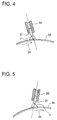
- Fig. 4 is a conceptual drawing showing an example of blade cleaning method.
- Fig. 5 is a conceptual drawing showing another example of blade cleaning method.
- the toner of the present invention has a BET specific surface area of not less than 5 m 2 , and this BET specific surface area is measured by one-point method based on nitrogen adsorption method, and specifically, by the use of Flow Soap 2300 measuring apparatus manufactured by Shimazu Seisaksho Co., Ltd.
- the toner of the present invention has a shape coefficient of 1.01 to 1.5, and further, more preferably, of 1.05 to 1.3.
- the shape coefficient is defined by a ratio of a circular equivalent length of a toner particle to the circular equivalent length of the toner particle, and more specifically, it is defined by the following formula.
- a shape Coefficient (the circular length of a toner)/(the circular equivalent length of the toner) L / (2 ⁇ A / ⁇ )
- L denotes the circular length of a toner particle ( ⁇ m)
- A denotes the projected area of the toner particle ( ⁇ m 2 ).
- L and A in the above formula are measured by projecting toner particles and measuring L and A of the projected image, and more specifically, the toner particles are enlarged 1,000 times by the SEM (Scanning Electron Microscope), and the projected image is photographed to measure L and A of 100 to 1,000 samples and then, each of average values of L and A is measured by the use of an image analyzer.
- SEM Sccanning Electron Microscope
- the toner of the present invention possessing the above-mentioned shape coefficient has not only a shape relatively similar to a spherical but also large surface area. It is considered that, since the toner of the present invention has the above-mentioned specific shape and the large surface, the objects of the present invention can be attained. That is to say, while having a shape relatively similar to a spherical and, at the same time, it has large surface area, and uniform electrification at the early stage can be performed. Therefore, it can be considered that it becomes possible to obtain toner showing enhanced developing speed, excellent durability, no fogging even in the use extending over a long period of time, and showing excellent transfer and cleaning properties, and more particularly, excellent blade-cleaning properties as mentioned.
- the toner of the present invention has a characteristic feature that BET specific surface area is not less than 5m 2 /g.
- the BET value is not more than 150 m 2 /g, preferably, not more than 100 m 2 /g, and, particularly preferably 5 to 50 m 2 /g.
- the BET value is preferably 5 to 40 m 2 /g and, more preferably, 10 to 40 m 2 /g.
- This BET specific surface area is measured by using one-point method of nitrogen adsorption method and, as a specific measuring equipment, "FLOWSORB 2300 (produced by Shimazu Seisakusho Co., Ltd.) can be mentioned.
- toner particles having excessively large BET specific surface area have a lot of fine uneven surface, so that manufacturing itself is difficult. Moreover, even if particles having this uneven surfaces are obtainable, the surface roughness may be finer than that required for electrification, so that effect will attain in the saturated state.
- the toner of the present invention at least comprises resin and a coloring agent. If necessary, the toner may be comprise a releasing agent, a charge controlling agent, etc. Further, external additives consisting of inorganic or organic fine particles may be added to colored particles composed of a resin and a colorant. In anyway, the toner particles of the present invention have high BET specific surface area.
- the toner of the present invention can be manufactured by, for example, adding necessary additives to monomers, mixing and emulsion polymerizing the mixture so as to make fine polymer particles, and ,thereafter, coagulating by adding other additives such as organic solvents, coagulant.
- the toner having the BET specific surface area of the present invention can be formed by a method of coagulating a plural kinds of fine particles consisting of resin, colorant, etc., and, in particular, after dispersing these constituents in water in the presence of an emulsifying agent, treating with a coagulant at a concentration of not less than their critical coagulation concentration, a nonionic surface active agent and an organic solvent being infinitely miscible with water, and thereafter performing heat fusion at a temperature of not less than the glass transition point of the produced polymer, the toner having the BET specific surface area of the present invention can be formed.
- the nonionic surface active agent is a surface active agent not having a ionic-dissociation group.
- a surface active agent having oxyethylene unit (-CH 2 CH 2 -O-) or oxypropylene unit is preferably used
- the nonionic surface active agent is added in an amount of 10 through 100 % by weight of produced polymer particles, and more preferably, the nonionic surface active agent is added in an amount of 50 through 100 % by weight of produced polymer.
- the above-mentioned nonionic surface active agent and the organic solvent being infinitely miscible with water may be employed simultaneously or separately. It is preferable that the nonionic surface active agent and the organic solvent being infinitely miscible with water are employed simultaneously.
- coagulated material is heated at a temperature of not less than the glass transition point (Tg) of the resin so as to form a fused material, and, preferably, the temperature is set to be Tg of the resin to Tg plus 50 °C of the resin, and more preferably, the temperature is set to be Tg to Tg plus 30 °C of the resin.
- Tg glass transition point
- the coagulated material is heated at the temperature of not less than the glass transition point of the resin for a time of 2 hours to 10 hours.
- monomers which constitute the resin for example, the following monomers can be preferably mentioned:
- Styrene or styrene derivatives thereof such as styrene, o-methylstyrene, m-methylstyrene, p-methylstyrene, p-chlorostyrene, 3,4-dichlorostyrene, p-phenylstyrene, p-ethylstyrene, 2,4-dimethylstyrene, p-t-butylstyrene, p-n-hexylstyrene, p-n-octylstyrene, p-n-nonylstyrene, p-n-decylstyrene and p-n-dodecyl styrene; methacrylate derivatives such as methyl methacrylate, ethyl methacrylate, n-butyl methacrylate, isopropyl methacrylate, isobuty
- vinyl-type monomers may be used either singly or two or more kinds in combination. Moreover, it is preferable that monomers having an ionic dissociating group are used in combination as monomers which constitutes the resin.
- the monomer containing an ionic dissociating group as a constituent of the monomer includes, for example, a carboxyl group, a sulfo group and a phospho group.
- these ionic dissociation groups are substituted by a multi-valent metal atom such as a zinc, a magnesium, and the resin forms a metal- bridged structure.
- a resin having a crosslinking structure may also be formed.
- These monomers may be polymerized by using a radical polymerization initiator so as to form a resin.
- a radical polymerization initiator may also be used in a suspension polymerization method and a solution polymerization method.
- the oil-soluble polymerization initiator for example, azoisobutylonitrile, lauryl peroxide, benzoyl peroxide, etc. may be used.
- a water-soluble radical polymerization initiator may be used.
- water-soluble polymerization initiator for example, persulfates such as potassium persulfate or ammonium persulfate, azobisaminodipropane acetate, azobiscyanovaleic acid or salts thereof, hydroxy peroxide, etc. may be mentioned.
- resins having the glass transition point of 20°C to 90°C are preferably employed, and resins having the softening point of 80°C to 220°C are preferably employed.
- the glass transition point is measured by differential thermal analysis, and the softening point can be measured by a descending type flow tester.
- a number average molecular weight (Mn) of the resin is 1,000 to 500,000, and preferably, 1,000 to 100,000.
- a weight average molecular weight (Mw) of the resin is 2,000 to 1,000,000, and preferably, 2,000 to 100,000.
- Mn and Mw are measured by gel permeation chromatography (GPC). Still further, as a molecular weight distribution, Mw/Mn is not more than 100, preferably, not more than 70, more preferably, less than 5.0, and particularly preferably, 2.0 to 3.0.
- Measurement of the molecular weight by GPC is carried out by flowing tetrahydrofurane at the flow rate of 1.0 ml/min at 40°C and is measured by sampling 100 ⁇ l of 0.01 g of resin/20 ml of tetrahydrofuran.
- a molecular weight of a sample is measured at a specific measurement condition, wherein a calibration curve is prepared by measuring some monodispersed polystyrenes, and the correlation between a logarithm of the molecular weight of the calibration curve and a count number of the calibration curve becomes linear.
- a peak molecular weight is calculated by the use of the above-mentioned calibration curve with reference to the count number of the obtained GPC chromatography.
- the resin when the resin is particularly obtained by emulsion polymerization, the resin is prepared in the form of fine particles, and then, adding a coagulant, a solvent which is infinitely miscible with water, and the resin thus obtained is heated at the temperature higher than the glass transition point of the resin, preferable resin particles for toner can be obtained.
- a coagulant used in the manufacture of the toner of the present invention there is no specific limitation as to a coagulant used in the manufacture of the toner of the present invention, however, the coagulants selected from metal salts are preferable.
- mono-valent metals for example, metal salts of an alkaline metal such as sodium, potassium, lithium, etc.
- di-valent metals for example, metal salts of alkaline earth metals such as calcium, magnesium, etc., salts of divalent metals such as manganese, copper, etc., salts of tri-valent metals such as iron, aluminum, etc.
- sodium chloride, potassium chloride, lithium chloride, calcium chloride, zinc sulfate, copper sulfate, magnesium sulfate, manganese sulfate, etc. can be mentioned. These compounds may also be used in combination.
- the critical coagulation concentration is an index showing stability of aqueous dispersions, and indicates the concentration at which coagulations take place.
- This critical coagulation concentration varies to a large extent depending on the nature of the constituent to be dispersed and the dispersant itself. These are described in, for example, "Polymer Chemistry edited by the Society of Polymer Chemistry of Japan", Vol.1, 17, page 601 (1960), authorized by Seizo Okamura et al., and, thereby, detailed critical coagulation concentrations values can be obtained.
- the specified salt concentration can be defined as the critical coagulation concentration of the dispersion.
- the amount of the coagulant added in the present invention may be optional as long as the concentration of not less than the critical coagulation concentration, but is preferably at least 1.2 times, and more preferably at least 1.5 times that of the critical coagulation concentration.
- Solvents being infinitely miscible with water are defined as solvents being infinitely soluble in a dyed polymer dispersion, so called, an aqueous dispersion, and this solvent is selected from the solvents wherein the produced resins are not soluble in the solvents. More specifically, They include, for example, alcohols such as methanol, ethanol, propanol, isopropanol, t- butanol, methoxyethanol and butoxyethanol, etc.; nitriles such as acetonitrile, etc. and ethers such as dioxane, etc. can be mentioned. Particularly, ethanol, propanol, isopropanol, are preferably employed.
- the addition amount of this infinitely water-miscible solvent is preferably 1 to 300% by volume of the polymer-containing dispersion, into which the coagulant has been added.
- a variety of methods can be applied as polymerization method for forming the resin used for the toner of the present invention, and particularly, the above-mentioned emulsion polymerization method can be preferably employed.
- coloring agents which can be employed in the toner of the present invention, carbon black, magnetic material, dyes and pigments can be used voluntarily.
- carbon black for example, Channel black, Farness black, acetylene black, thermal black, lamp black, etc.
- magnetic materials are ferromagnetic metals such as iron, nickel, cobalt, etc.; alloys containing these metals; compounds of the ferromagnetic metals such as ferrite, magnetite, etc.; alloys, which do not contain ferromagnetic metals but show ferromagnetic nature with heat treatment, such as so-called Heusler alloy like manganese-copper-aluminum alloy, manganese-copper-tin alloy, chromium dioxide, etc.
- Dye example are C.I. Solvent Red Nos.1, 49, 52, 58, 63, 111 and 122; C.I. Solvent Yellow Nos. 19, 44, 77, 79, 81, 82, 93, 98, 103, 104, 112 and 162; C.I. Solvent Blue Nos. 25, 36, 60, 70, 93 and 95, etc., and these dyes may be used in combination.
- pigments for example, C.I. Pigment red Nos. 5, 48:1, 53:1, 57:1, 122, 139, 144, 149, 166, 177, 178, 222; C.I. Pigment orange Nos.31 and 43; C. I.
- Pigment yellow Nos.14, 17, 93, 94, 138; C.I. Pigment green No.7; and C,I. Pigment blue Nos.15:3, and 60, etc. can be used. These pigments may also be used in combination. These coloring agents having primary particles having number average primary particle size of about 10 to 200 nm, are preferably dispersed into the toner.
- coloring material a method, in which first prepare a polymer resin itself by emulsion polymerization, and then add the coloring agent in the step of coagulating the resin by adding the coagulant, or a method of adding the coloring agent in the step of polymerization of monomer, may be used.
- the coloring agent is added in the step of preparing the polymer, it is preferable to treat the surface of the polymer with a coupling agent etc., in order that radical polymerization is not restricted.
- low molecular weight polypropylene having a number average molecular weight of 1,500 to 9,000, or low molecular weight polyethylene may be added.
- charge controlling agents azo-type metal complexes or quaternary ammonium salts may also be used.
- inorganic or organic fine particles may be added to colored resin particles obtained from polymerization.
- inorganic fine particles are preferably used, and inorganic oxide particles such as silica, titania or alumina, etc. is also preferably used.
- silane coupling agent, a titanium coupling agent. etc. these inorganic fine particles are preferably conducted with hydrophobicity providing processing.
- the toner of the present invention can be prepared by coagulating plurality of the above-mentioned polymers, and, in this case, it can be obtained by the following steps comprising:
- a particle size of the toner itself of the present invention is optional, however, the smaller the particle size is, the more remarkable is the improved effect of the present invention.
- Toner particles having a volume average particle size of 2 to 10 ⁇ m, are preferably employed, and, in particular preferably 3 to 9 ⁇ m.
- This particle size can be controlled by coagulant concentration, addition amount of the solvent, or constituents of the polymer itself.
- the toner of the present invention can be used in either case: when it is used as a mono-component magnetic toner, by incorporating a magnetic material in the resin, when it is used as a two-component developer by mixing with so-called carrier particles, or when the colored resin particles themselves are used as non-magnetic toner.
- carrier which constitutes a two-component developer
- non-coated carrier consisting of only magnetic particle such as iron or ferrite
- resin-coated carrier consisting of magnetic material surface coated with a resin
- a volume average particle size of this carrier particles is preferably 30 to 150 ⁇ m.
- resin used for coating the carrier particles for example, styrene-acrylic resin can be mentioned
- Layer thickness of the developer comprising the toner of the present invention at the development domain on the photoreceptor is 0.1 through 8 mm and preferably, 0.4 through 5 mm.
- gap between the photoreceptor and the developer carrying member is preferably 0.15 through 7 mm, and more preferably, 0.2 through 4 mm.
- developer layer formed on the developer carrying member does not contact with the photoreceptor.
- the developer layer applied to this method is preferably formed with a thin layer.
- the developer layer having a thickness of 20 through 500 ⁇ m is formed on the developing domain on the developer carrying member, and the gap between the photoreceptor and the developer carrying member is not less than the developer layer thickness.
- the toner of the present invention has excellent charge rising property, and is preferably employed for the non-contact developing method. Namely, a developing electric field varies to a large extent in the non-contact developing method, and even if a charge amount varies to a very small amount, developing performance is remarkably affected. In other words, even if a charged amount of a toner varies to a very small amount, a developing performance such as an image quality and a density etc., varies to a large extent. However, since the toner of the present invention has an excellent charge rising property, a charge amount varies to a small amount, and a stable charged amount can be obtained. Accordingly, even if a non-contact developing method is employed, a stable image can be formed for a long period of time.
- non-contact developing method formation of the thin developer layer can be formed by using a magnetic blade, in which magnetic force is used, or a method of press-contacting a developer layer thickness-regulating member on the surface of the developer carrying member. Moreover, a method of contacting a urethane blade or a plate made of phosphor bronze and regulating the thickness of the developer layer can also be applied.
- Pressing force of the press-regulation member is preferably 1 to 15 gf/mm. when the pressing force is too small, transport of the developer tends to be unstable due to lack of regulating power. On the other hand, when the pressing force is too big, durability of the developer tends to deteriorate because of increased stress of the developer. Therefore, it is preferable that pressing force range is 3 to 10 gf/mm. Further, when development bias may be applied in the non-contact developing method, a direct current component only may be applied or an alternating current component may be applied.
- size of the developer carrying member one having diameter of 10 to 40 mm ⁇ is preferable.
- the diameter is too small, the degree of mixing of the developer tends to be insufficient, and it is difficult to provide sufficient electrification on the toner particles.
- the diameter is too large, centrifugal force to the developer tends to be large, and problem of scattering of the toner particles into the air is easily be caused.
- Fig. 1 is a conceptual drawing of a developing device which is suitably be used in the non-contact developing method.
- numerical symbol respectively denote as follows:
- 1 shows a photoreceptor
- 2 shows a developer carrying member
- 3 shows a two-component developer containing a toner of the present invention
- 4 shows a developer layer thickness-regulating member
- 5 shows a developing domain
- 6 shows a developer layer
- 7 shows a power source for forming an alternating electric field
- the two-component developer comprising the toner of the present invention is held by magnetic force on the developer carrying member 2, inside of which holds a magnet 2B, and is transported to the developing domain 5 by the movement of the development sleeve 2A.
- thickness of the developer layer 6 is regulated by the developer layer thickness- regulation member 4 in order that thickness does not contact with the photoreceptor 1 at the developing domain 5.
- the minimum distance (Dsd) of the developing domain is not less than the thickness of the developer layer 6, which is preferably not less than 20 to 500 ⁇ m, and is, for example, about 100 to 1,000 ⁇ m.
- the power source 7 to form the alternating electric field is preferably an alternating current having a frequency of 1 to 10 kHz and electric potential of one to three kVp-p.
- the power source 7, if necessary, may contain direct current component added to an alternative current in series. As direct current potential, 300 to 800V is preferable.
- a developing device in which holds a magnet 2B is used, and as a sleeve 2A which constitute the surface of the developer carrying member, aluminum, aluminum subjected to surface oxidation processing or stainless steel can be used.
- Item 11 shows the charging device, which is an electrification electrode
- Item 12 shows a developing unit consisting of four developing vessels in which yellow, magenta, cyan and black toners are respectively loaded, and four vessels are separated in accordance with the above-mentioned four colors toners.
- 14 shows photoreceptor drum
- 13 shows cleaning unit
- 15 shows a transfer drum, upon which a monochromatic color toner image is temporarily held, further, next monochromatic toner image is also held temporarily on the monochromatic color image, and, finally, an objective multi-color image is formed.
- 16 shows a transport unit which conveys a transfer material, onto which the toner image on the transfer drum is transferred
- 17 shows an adsorption electrode which is provided inside the transfer drum 15, corona charging from within the transfer drum 15 and electrostatically adsorbing the transfer material on the drum
- 18 shows a transfer electrode, with which the toner images formed on the photoreceptor 14 are successively transferred onto the transfer drum
- 19 shows a peeling electrode to peel off the transfer material which was electrostatically adsorbed onto the transfer drum
- 20 shows an eliminating electrode used to remove residual charge on the transfer drum after peeling off of the transfer material.
- Uniform electrification is performed on the photoreceptor drum 14 using a charging electrode 11, and, thereafter an electrostatic latent image is formed by imagewise exposure (of which means is not shown in the drawing).
- This electrostatic latent image is developed with one color toner of developing unit 12 (for example, black toner) to form a toner image of a color on the photoreceptor 14.
- a transfer material which was transported on the transfer drum 15 by a transport unit 16, is electrostatically adsorbed on the transfer drum 15 by a n adsorption electrode 17 and transported to the transfer portion.
- the above-mentioned toner image formed on the transfer drum 14 is transferred onto this transfer material.
- a toner is remained as a residual toner on the transfer drum 14 after transferred, then, this residual toner is collected by cleaning unit 13, and the collected toner is recycled in the next process.
- the multi-colored toner images are formed by similar processes, specifically, a toner image having a color is formed by a developing, and then, the toner image is serially transferred on a transfer drum 15. Finally, an objective toner image is formed on a transfer material adsorbed on the transfer drum 15.
- the transfer material on which the required toner image was produced is removed with the peeling off electrode 19, and is transported to the fixing section, to produce a final fixed multi-color toner image.
- a residual charge on the transfer drum 15 is removed by using a discharger 20, and the transfer drum is employed in the next process.
- Denotations of the respective portions of the equipment shown in Fig. 3 are omitted because they have the same denotations as Fig. 2, with the exception that item number 21 represents a transport section to transfer the toner image during transferred of the transfer material.
- Uniform electrostatic charges are formed by the electrification electrode on the photoreceptor drum 14, and, thereafter, an electrostatic latent image is formed by a latent image forming means, which is not illustrated in the drawing.
- This electrostatic latent image is developed with one of the color toners, for example, such as a black toner, installed in the developing unit 12, to form a toner image in one color on the photoreceptor drum.
- this toner image is formed on the photoreceptor drum as it is, without being transferred, and, then the photoreceptor drum which bears the toner image, again uniformly charged with the electrification electrode 11, an electrostatic latent image is further formed, developed with a toner with a different color from that used in the first development, and, thus a toner image of another color is superimposed on the prior formed toner image.
- cleaning unit 13, transfer electrode 18 and transport section 21 are not active and withdrawn from the vicinity of the photoreceptor drum 14, so that they may not interfere with the just formed toner image.
- the toner image on the photoreceptor drum is transferred onto the transfer material transferred by a transfer unit 16, by the transfer electrode 18, while being transported by the transport section 21.
- the transfer material carrying the transferred toner image is transported to the fixing section, and, there, the toner image is fixed so as to form final multi-color toner images on the transfer material.
- toner is remained on the photoreceptor drum 14, and the toner is removed by the cleaning unit 13 and, the photoreceptor drum 14 is employed for the next process.
- the toner image formed on the photoreceptor by the above-mentioned various methods is transferred in the transfer step onto a transfer material such as a paper.
- a transfer material such as a paper.
- various methods such as so-called a corona transfer method or a roller transfer method, etc. can be employed.
- the toner of the present invention has high transfer efficiency, and residual toner on the photoreceptor is small amount, for example, in the case of employing the toner in a blade-cleaning method, pressure of a cleaning blade on the photoreceptor material can be reduced, and further, the toner of the present invention provides longer life of the photoreceptor.
- residual toner on the photoreceptor is removed by the cleaning step, and the photoreceptor can be repeatedly employed for next process.
- a preferable method is a blade cleaning method using so called, a cleaning blade in view of the reasons given herein-above.
- a cleaning blade 31 is held by a holder 33.
- item number 32 denotes a photoreceptor
- item number 34 denotes the direction towards which the photoreceptor drum 32 rotates.
- Item ⁇ shows an angle formed by the holder 33 and the photoreceptor 32, and in either case of Fig. 4 or Fig. 5, this angel ⁇ is usually set to be 10 through 90°, and preferably, 15 through 75°.
- an elastic body such as silicone rubber or urethane rubber, etc. may be used.
- Preferable thickness of the cleaning blade 31 is 1.5 to 5 mm, length of the holder member is preferably 5 to 20 mm, and compressing force against the photoreceptor is preferably 5 to 50 gf/mm.
- a primary particle diameter of the dispersion 1 is measured by a light-scattering electrophoresis particle-size analyzer ELS-800 (manufactured by Otsuka Denshi Kogyo co.,), and a molecular weight distribution of the dispersion 1 was measured by gelpermeation chromatography (GPC) in terms of styrene polymer.
- GPC gelpermeation chromatography
- Colored particles 2 of the present invention were pre pared in the same manner as manufacturing example 1, except that C. I. Pigment Blue 15:3 was used instead of the surface-treated carbon black of manufacturing example 1.
- Dispersion 2 and obtained color particles are hereinafter referred to as “Colored particles 2", respectively.
- Colored particles 3 of the present invention were pre pared in the same manner as manufacturing example 1, except that C. I. Pigment Red 122 was used instead of the surface-treated carbon black of manufacturing example 1.
- the dispersion and the colored particles obtained in this example are hereinafter referred to as" Dispersion 3" and “Colored particles 3",respectively.
- Colored particles 4 of the present invention were pre pared in the same manner as manufacturing example 1, except that C. I. Pigment Yellow 17 was used instead of the surface-treated carbon black of manufacturing example 1.
- the dispersion and the colored particles obtained in this example are hereinafter referred to as" Dispersion 4" and "Colored particles 4", respectively.
- Colored particles 5 of the present invention were pre pared in the same manner as manufacturing example 1, except that 150 ml of isopropyl alcohol added to "Dispersion 1" of manufacturing example 1.
- Dispersion 5" and Cold particles 5" respectively.
- Colored particles 6 of the present invention were pre pared in the same manner as manufacturing example 2, except that 250 ml of aqueous solution containing potassium chloride of 2.7 mol/l were added to "Dispersion 2" of manufacturing example 2.
- the colored particles obtained in this example is hereinafter referred to as "Colored particles 6".
- Colored particles 7 of the present invention were prepared in the same manner as manufacturing example 3, except that 68 ml of isopropyl alcohol and 200 ml of aqueous solution containing potassium chloride of 2.7 mol/l were added to Dispersion 3 of manufacturing example 3, respectively..
- the colored particles obtained in this example is hereinafter referred to as "Colored particles 7".
- Colored particles 8 of the present invention were prepared in the same manner as manufacturing example 4, except that "Dispersion 4" was used, and 72ml of isopropyl alcohol and 200 ml of aqueous solution containing potassium chloride of 2.7 mol/l were added to Dispersion 4 of manufacturing example 4, respectively.
- the colored particles obtained in this example is hereinafter referred to as "Colored particles 8".
- Comparative colored particles 2 were prepared in the same manner as Comparative manufacturing example 1, except that C. I. Pigment Blue 15:3 was used instead of carbon black. Thus comparative colored particles were obtained.
- the comparative colored particles obtained in this example are hereinafter referred to as "Comparative Colored particles 2".
- Comparative colored particles 3 were prepared in the same manner as Comparative manufacturing example 1, except that C. I. Pigment Red 122 was used instead of carbon black.
- the colored particles obtained in this example is hereinafter referred to as "Comparative Colored particles 3".
- Comparative colored particles 4 were prepared in the same manner as Comparative manufacturing example 1, except that C. I. Pigment Yellow 17 was used instead of carbon black.
- the colored particles obtained in this example is hereinafter referred to as "Comparative Colored particles 4".
- each molecular weight distribution is measured by the following condition, and, a peak molecular weight, a weight average molecular weight (Mw), a number average molecular weight (Mn) and Mw/Mn are calculated respectively.
- a molecular weight measurement condition Apparatus HLC-8020 (produced by Toso Co.,). Column GMHXL 2 columns, G2000HXL 1 column.
- Detector RI Rate of eluate 1.0 ml/minutes Sample concentration 0.01 g/20ml of THF (tetrahydrofuran) Sampling amount 100 ⁇ l of Sample Calibration curve Calibration curve is prepared by standard polystyrenes.
- the toner particles are enlarged 1,000 times by the SEM (Scanning Electron Microscope), and the projected image is photographed to measure each L and each A of 150 samples by SPICCA (produced by NIPPON AVIONICS CO.,) and then, each of average values of L and A is calculated.
- SEM Sccanning Electron Microscope
- the above-mentioned toners were mixed with ferrite carrier having a volume average particle diameter of 50 ⁇ m and being coated with a styrene-acrylic resin, so as to form developers having toner concentration of 7 % by weight.
- the developers corresponding to the above-mentioned “Toner 1" through “Toner 8" and “Comparative Toner 1” through “Comparative Toner 4" are referred to as “Developer 1" through “Developer 8" and “Comparative Developer 1" through “Comparative Developer 4", respectively.
- the following copying apparatus was employed.
- Evaluation was carried out by using a copying machine U-Bix3135, a product of Konica Corporation.
- thickness of developer layer was set to be 1.5 mm
- gap(Dsd between the photoreceptor and the developer carrier was set to be 0.5 mm.
- a cleaning device one having the structure shown in Fig. 5, and the angle ⁇ formed by the holder 33 and the photoreceptor 32 was 22°, and urethane rubber was used as the material used for constituting the cleaning blade 31.
- the rubber hardness of this urethane rubber was 65°, and thickness and the length of the holder member were 8 mm. Further, contacting force on the photoreceptor was 15 gf/mm.
- Fog density was measured by using Macbeth densitometer Type Rd-918 and is represented as relative density when the density of the paper was normalized as zero. Further, for this evaluation, "Developer 1", “Developer 4", “Developer 5" and “Comparative Developer 1 were used. Developer No.
- Non-contact developing method was explained with referring to Fig. 3. Applying this developing method a color copying apparatus U-Bix9028 (a product of a Konica Corporation) was employed. Simultaneous transfer method was performed in the similar manner as shown in Fig. 3, and one by one transfer method was performed in the similar manner as shown in Fig. 2. Image processing of the two type transfer methods is carried out by the following conditions.
- a negatively electrifying lamination-type photoreceptor was employed as a photoreceptor, and as exposing light source a semi-conductive laser were used, respectively. And reversal development was carried out.
- Photoreceptor surface potential -550 V
- DC bias -250 V
- AC bias Vp-p: -50 to -450V
- Alternating frequency of the electric field 1,800 Hz
- Dsd 300 ⁇ m
- Pressure regulating force 10 gf/mm
- Pressure regulation bar SUS416 (made of magnetic stainless)/: 3 mm ⁇ Developer layer thickness: 150 mm Development sleeve: 20 mm
Description
- 1
- Photoreceptor
- 2
- Developer carrier
- 2A
- development sleeve
- 2B
- Magnet
- 3
- Two-component developer containing toner of the present invention.
- 4
- Developer layer thickness regulating member
- 5
- Development domain
- 6
- Developer Layer
- 7
- Power source for forming an alternating electric field
- 11
- Charging device
- 12
- Developing device
- 13
- Cleaning unit
- 14
- Photoreceptor drum
- 15
- Transfer drum
- 16
- Transport unit
- 17
- Adsorption electrode
- 18
- Transfer electrode
- 19
- Peeling-off electrode
- 20
- de-electrification electrode
- 21
- Transport section
- 31
- Cleaning blade
- 33
- Holder
- 34
- Direction of rotation of photoreceptor

| (Dispersions) | ||||
| Sample No. | Number Aerage Prmary Patcle Damter (µm) | Weight Aeage Mleclar Weight (Mw) | Number Aeage Mlecular Weight (Mn) | Mw/Mn |
| Dispersion 1 | 0.18 µm | 2.07 x 10⁴ | 9.50 x 10³ | 2.18 |
| | 0.25 µm | 1.85 x 10⁴ | 8.81 x 10³ | 2.10 |
| | 0.32 µm | 1.66 x 10⁴ | 7.23 x 10³ | 2.30 |
| | 0.48 µm | 1,98 x 10⁴ | 8.79 x 10³ | 2.26 |
| A molecular weight measurement condition | ||
| Apparatus | HLC-8020 (produced by Toso Co.,). | |
| | GMHXL | 2 columns, G2000HXL 1 column. |
| Detector | RI | |
| Rate of eluate | 1.0 ml/minutes | |
| Sample concentration | 0.01 g/20ml of THF (tetrahydrofuran) | |
| Sampling amount | 100 µl of Sample | |
| Calibration curve | Calibration curve is prepared by standard polystyrenes. |
| (Colored Particles) | ||||||
| Sample | Volume Average Particle Diamter (µm) | BET Value | Shape coefficient | Mw × 104 | Mn × 103 | Mw/Mn |
| Colored Particles 1 | 5.60 | 22.1 | 1.129 | 2.07 | 9.50 | 2.18 |
| | 5.32 | 20.4 | 1.134 | 1.85 | 8.81 | 2.10 |
| | 5.21 | 24.6 | 1.140 | 1.66 | 7.23 | 2.30 |
| | 5.56 | 26.7 | 1.151 | 1.98 | 8.79 | 2.26 |
| Colored Particles 5 | 7.52 | 14.7 | 1.095 | 2.07 | 9.50 | 2.18 |
| Colored Particles 6 | 5.15 | 17.8 | 1.042 | 1.85 | 8.81 | 2.10 |
| | 5.59 | 37.2 | 1.342 | 1.66 | 7.23 | 2.30 |
| Colored Particles 8 | 5.73 | 30.5 | 1.311 | 1.98 | 8.79 | 2.26 |
| Comparative Colored Particles 1 | 5.91 | 3.21 | 1.193 | 26.0 | 9.0 | 28.89 |
| Comparative | 6.01 | 3.29 | 1.191 | 26.0 | 9.0 | 28.89 |
| Comparative | 5.82 | 3.93 | 1.205 | 26.0 | 9.0 | 28.89 |
| Comparative | 5.92 | 3.87 | 1.189 | 26.0 | 9.0 | 28.89 |
| (Toner) | ||
| Sample | Volume Average Paticle Diameter (µm) | BET Value |
| Toner 1 | 5.60 | 21.9 |
| | 5.32 | 21.8 |
| | 5.21 | 23.7 |
| | 5.56 | 28.4 |
| Toner 5 | 6.23 | 14.9 |
| Toner 6 | 8.44 | 19.1 |
| | 5.73 | 33.7 |
| Toner 8 | 5.80 | 28.5 |
| Comparative Toner 1 | 5.91 | 3.41 |
| | 6.01 | 3.51 |
| | 5.82 | 4.01 |
| | 5.92 | 3.69 |
| Developer No. | At the Beginning | After 10,000th Copy | After 20,000th Copy | After 30,000th Copy | After 40,000th Copy | After 50,000th Copy | After 60,000th Copy |
| Developer 1 | 0.00 | 0.001 | 0.001 | 0.001 | 0.001 | 0.002 | 0.002 |
| | 0.00 | 0.001 | 0.001 | 0.001 | 0.001 | 0.002 | 0.002 |
| Developer 5 | 0.00 | 0.001 | 0.001 | 0.001 | 0.001 | 0.002 | 0.002 |
| | 0.00 | 0.002 | 0.003 | 0.004 | 0.006 | 0.009 | 0.012 |
| Photoreceptor surface potential: -550 V |
| DC bias: -250 V |
| AC bias: Vp-p: -50 to -450V |
| Alternating frequency of the electric field: 1,800 Hz |
| Dsd: 300 µm |
| Pressure regulating force: 10 gf/mm |
| Pressure regulation bar: SUS416 (made of magnetic stainless)/: 3 mm |
| Developer layer thickness: 150 mm |
| Development sleeve: 20 mm |
| (One by one transfer method) | |
| Developer | Number of Copies at which Uneven Transfer Took Place |
| developers 1 through 4 | Not observed |
| Developer 5 through 8 | Not observed |
| Comparative Developer 1 through 4 | Uneven transfer was observed at 4000th copy |
| (Simultaneous Transfer method) | |
| Developer | Number of Copies at which Uneven Transfer Took Place |
| developers 1 through 4 | Not observed |
| Developer 5 through 8 | Not observed |
| Comparative Developer 1 through 4 | Uneven transfer was observed at 4000th copy |
Claims (10)
- A toner for developing an electrostatic latent image, said toner having BET specific surface area of not less than 5m2/g.
- The toner of claim 1, wherein said toner has a shape coefficient of 1.01 to 1.5.
- The toner of claim 1 or 2, wherein said toner comprises a resin having a ratio of a weight average molecular weight (Mw) to a number average molecular weight (Mn) of not more than 70.
- The toner of claim 1, 2 or 3, wherein said toner comprises a resin having a ratio of a weight average molecular weight (Mw) to a number average molecular weight (Mn) of less than 5.
- The toner of claim 3 or 4, wherein said resin has a weight average molecularweight (Mw) of 2,000 to 1,000,000, and has a number average molecular weight (Mn) of 1,000 to 500,000.
- The toner of any of claims 1 to 5, wherein said toner is prepared by a method of coagulating a plurality of particles, said particles comprising a resin and a colorant.
- The toner of any of claims 1 to 6, wherein said toner is prepared by a method of coagulating a plurality of particles, said method comprising steps of:(a) dispersing a plurality of particles in water in the presence of an emulsifying agent, wherein said particles comprising a resin and a colorant,(b) adding a coagulant so as to have a concentration of not less than a critical coagulation concentration of the dispersing material,(c) adding an organic solvent being infinitely miscible with water,(d) adding a nonionic surface active agent, and(e) heating said coagulated material at a temperature of not less than the glass transition point of said resin so as to form a fused material.
- The toner of any of claims 2 to 7, wherein said toner has a shape coefficient of 1.05 to 1.3.
- The toner of any of claims 1 to 8, wherein said toner comprises a resin having a ratio of a weight average molecular weight (Mw) to a number average molecular weight (Mn) of 2 to 3.
- A developer for developing an electrostatic latent image, said developer comprising a toner having BET specific surface area of not less than 5m2/g.
Applications Claiming Priority (6)
| Application Number | Priority Date | Filing Date | Title |
|---|---|---|---|
| JP13671695 | 1995-06-02 | ||
| JP13671695 | 1995-06-02 | ||
| JP136716/95 | 1995-06-02 | ||
| JP24134195 | 1995-09-20 | ||
| JP241341/95 | 1995-09-20 | ||
| JP24134195 | 1995-09-20 |
Publications (3)
| Publication Number | Publication Date |
|---|---|
| EP0745904A2 EP0745904A2 (en) | 1996-12-04 |
| EP0745904A3 EP0745904A3 (en) | 1997-07-02 |
| EP0745904B1 true EP0745904B1 (en) | 2000-08-09 |
Family
ID=26470219
Family Applications (1)
| Application Number | Title | Priority Date | Filing Date |
|---|---|---|---|
| EP96108674A Expired - Lifetime EP0745904B1 (en) | 1995-06-02 | 1996-05-30 | Toner for developing an electrostatic latent image, developer and a method of producing an image using the toner |
Country Status (3)
| Country | Link |
|---|---|
| US (1) | US5830617A (en) |
| EP (1) | EP0745904B1 (en) |
| DE (1) | DE69609670D1 (en) |
Cited By (1)
| Publication number | Priority date | Publication date | Assignee | Title |
|---|---|---|---|---|
| US20100173003A1 (en) * | 2007-05-24 | 2010-07-08 | Amcol International | Composition and method for encapsulating benefit agents |
Families Citing this family (6)
| Publication number | Priority date | Publication date | Assignee | Title |
|---|---|---|---|---|
| US6009299A (en) * | 1998-01-08 | 1999-12-28 | Oki Data Corporation | Electrophotographic imaging apparatus using multi-layered toner |
| US6717602B2 (en) * | 1999-07-02 | 2004-04-06 | Konica Corporation | Image forming method and image forming apparatus, and electrostatic latent image developing toner used by the same |
| JP3900785B2 (en) * | 2000-03-30 | 2007-04-04 | コニカミノルタホールディングス株式会社 | Image forming method, image forming apparatus, and developing toner used therefor |
| JP4144167B2 (en) * | 2000-07-17 | 2008-09-03 | コニカミノルタホールディングス株式会社 | Toner for developing electrostatic image and image forming method |
| JP3997724B2 (en) * | 2001-04-26 | 2007-10-24 | コニカミノルタホールディングス株式会社 | Image forming method using toner for developing electrostatic image |
| JP6589385B2 (en) | 2015-05-29 | 2019-10-16 | 富士ゼロックス株式会社 | Developing device, image forming apparatus, process cartridge, and image forming method |
Family Cites Families (8)
| Publication number | Priority date | Publication date | Assignee | Title |
|---|---|---|---|---|
| KR100186872B1 (en) * | 1989-05-23 | 1999-05-01 | 앤드류 가르만 | Stain elimination in consecutive color toning |
| US5139914A (en) * | 1989-07-28 | 1992-08-18 | Canon Kabushiki Kaisha | Developer for developing electrostatic images and image forming apparatus |
| JP2805653B2 (en) * | 1990-03-08 | 1998-09-30 | 日本ゼオン株式会社 | Non-magnetic one-component developer |
| EP0535246B1 (en) * | 1991-04-19 | 1996-09-11 | Fujitsu Limited | Non-magnetic component developing method |
| JP3126511B2 (en) * | 1992-09-10 | 2001-01-22 | キヤノン株式会社 | Non-magnetic one-component developer and image forming method |
| JP3367987B2 (en) * | 1993-02-15 | 2003-01-20 | コニカ株式会社 | Pigment-containing polymer particles, method for producing the same, electrophotographic toner, and carrier for immunological diagnostic reagent |
| JP3653736B2 (en) * | 1993-05-18 | 2005-06-02 | コニカミノルタホールディングス株式会社 | Non-spherical particles and method for producing the same |
| US5547804A (en) * | 1994-03-29 | 1996-08-20 | Dai Nippon Printing Co., Ltd. | Liquid toner, ink composition, and methods of producing the same |
-
1996
- 1996-05-29 US US08/654,702 patent/US5830617A/en not_active Expired - Lifetime
- 1996-05-30 DE DE69609670T patent/DE69609670D1/en not_active Expired - Lifetime
- 1996-05-30 EP EP96108674A patent/EP0745904B1/en not_active Expired - Lifetime
Cited By (1)
| Publication number | Priority date | Publication date | Assignee | Title |
|---|---|---|---|---|
| US20100173003A1 (en) * | 2007-05-24 | 2010-07-08 | Amcol International | Composition and method for encapsulating benefit agents |
Also Published As
| Publication number | Publication date |
|---|---|
| EP0745904A3 (en) | 1997-07-02 |
| DE69609670D1 (en) | 2000-09-14 |
| US5830617A (en) | 1998-11-03 |
| EP0745904A2 (en) | 1996-12-04 |
Similar Documents
| Publication | Publication Date | Title |
|---|---|---|
| US6296980B1 (en) | Toner for developing electrostatic image and image forming method | |
| US5837414A (en) | Toner for developing electrostatic image and method for forming multicolor image | |
| US6346356B1 (en) | Toner, toner production process, and image-forming method | |
| US6635398B1 (en) | Dry toner, dry toner production process, and image forming method | |
| EP1693712B1 (en) | Electrostatic image developing toner | |
| EP0745904B1 (en) | Toner for developing an electrostatic latent image, developer and a method of producing an image using the toner | |
| US6703177B2 (en) | Image forming method using a toner for developing a static image | |
| JP3953121B2 (en) | Toner for developing electrostatic image and image forming method | |
| JP4033252B2 (en) | Toner for developing electrostatic image, method for producing the same, and image forming method | |
| EP1645916A2 (en) | Electrostatic charge image developing toner | |
| US6780558B2 (en) | Image forming method | |
| US6841328B2 (en) | Image forming method | |
| US7470496B2 (en) | Electrostatic image developing toner | |
| JPH09179331A (en) | Electrostatic charge latent image developing toner developer and image forming method | |
| US5863691A (en) | Toner for developing electrostatic latent image developer and method for producing image | |
| US20080008945A1 (en) | Toner, toner producing method and image forming method | |
| JP4026728B2 (en) | Toner for developing electrostatic image, developer and image forming method | |
| JP3834872B2 (en) | Toner for developing electrostatic latent image, developer and image forming method using the toner | |
| JP3692569B2 (en) | Toner for developing electrostatic latent image, developer and image forming method using the toner | |
| JP3643995B2 (en) | Toner for developing electrostatic image, developer and image forming method | |
| JPH09265210A (en) | Electrostatic charge image developing toner, developer, developing method and fixing method | |
| JP3765106B2 (en) | Color developer | |
| JPH09146304A (en) | Toner for developing electrostatic charge image, developer and image forming method | |
| JPH1090950A (en) | Electrostatic charge image developing toner, developer, and image forming method | |
| JPH09179349A (en) | Toner for developing electrostatic latent image, its production, developer using same and image forming method |
Legal Events
| Date | Code | Title | Description |
|---|---|---|---|
| PUAI | Public reference made under article 153(3) epc to a published international application that has entered the european phase |
Free format text: ORIGINAL CODE: 0009012 |
|
| AK | Designated contracting states |
Kind code of ref document: A2 Designated state(s): BE DE FR GB IT NL |
|
| PUAL | Search report despatched |
Free format text: ORIGINAL CODE: 0009013 |
|
| AK | Designated contracting states |
Kind code of ref document: A3 Designated state(s): BE DE FR GB IT NL |
|
| 17P | Request for examination filed |
Effective date: 19971211 |
|
| GRAG | Despatch of communication of intention to grant |
Free format text: ORIGINAL CODE: EPIDOS AGRA |
|
| 17Q | First examination report despatched |
Effective date: 19990526 |
|
| GRAG | Despatch of communication of intention to grant |
Free format text: ORIGINAL CODE: EPIDOS AGRA |
|
| GRAG | Despatch of communication of intention to grant |
Free format text: ORIGINAL CODE: EPIDOS AGRA |
|
| GRAH | Despatch of communication of intention to grant a patent |
Free format text: ORIGINAL CODE: EPIDOS IGRA |
|
| GRAH | Despatch of communication of intention to grant a patent |
Free format text: ORIGINAL CODE: EPIDOS IGRA |
|
| GRAA | (expected) grant |
Free format text: ORIGINAL CODE: 0009210 |
|
| AK | Designated contracting states |
Kind code of ref document: B1 Designated state(s): BE DE FR GB IT NL |
|
| PG25 | Lapsed in a contracting state [announced via postgrant information from national office to epo] |
Ref country code: NL Free format text: LAPSE BECAUSE OF FAILURE TO SUBMIT A TRANSLATION OF THE DESCRIPTION OR TO PAY THE FEE WITHIN THE PRESCRIBED TIME-LIMIT Effective date: 20000809 Ref country code: IT Free format text: LAPSE BECAUSE OF FAILURE TO SUBMIT A TRANSLATION OF THE DESCRIPTION OR TO PAY THE FEE WITHIN THE PRESCRIBED TIME-LIMIT;WARNING: LAPSES OF ITALIAN PATENTS WITH EFFECTIVE DATE BEFORE 2007 MAY HAVE OCCURRED AT ANY TIME BEFORE 2007. THE CORRECT EFFECTIVE DATE MAY BE DIFFERENT FROM THE ONE RECORDED. Effective date: 20000809 Ref country code: FR Free format text: LAPSE BECAUSE OF FAILURE TO SUBMIT A TRANSLATION OF THE DESCRIPTION OR TO PAY THE FEE WITHIN THE PRESCRIBED TIME-LIMIT Effective date: 20000809 Ref country code: BE Free format text: LAPSE BECAUSE OF FAILURE TO SUBMIT A TRANSLATION OF THE DESCRIPTION OR TO PAY THE FEE WITHIN THE PRESCRIBED TIME-LIMIT Effective date: 20000809 |
|
| REF | Corresponds to: |
Ref document number: 69609670 Country of ref document: DE Date of ref document: 20000914 |
|
| PG25 | Lapsed in a contracting state [announced via postgrant information from national office to epo] |
Ref country code: DE Free format text: LAPSE BECAUSE OF FAILURE TO SUBMIT A TRANSLATION OF THE DESCRIPTION OR TO PAY THE FEE WITHIN THE PRESCRIBED TIME-LIMIT Effective date: 20001110 |
|
| NLV1 | Nl: lapsed or annulled due to failure to fulfill the requirements of art. 29p and 29m of the patents act | ||
| EN | Fr: translation not filed | ||
| PLBE | No opposition filed within time limit |
Free format text: ORIGINAL CODE: 0009261 |
|
| STAA | Information on the status of an ep patent application or granted ep patent |
Free format text: STATUS: NO OPPOSITION FILED WITHIN TIME LIMIT |
|
| 26N | No opposition filed | ||
| REG | Reference to a national code |
Ref country code: GB Ref legal event code: IF02 |
|
| PGFP | Annual fee paid to national office [announced via postgrant information from national office to epo] |
Ref country code: GB Payment date: 20140528 Year of fee payment: 19 |
|
| GBPC | Gb: european patent ceased through non-payment of renewal fee |
Effective date: 20150530 |
|
| PG25 | Lapsed in a contracting state [announced via postgrant information from national office to epo] |
Ref country code: GB Free format text: LAPSE BECAUSE OF NON-PAYMENT OF DUE FEES Effective date: 20150530 |