EP0745759B1 - Particulate trap for diesel engine - Google Patents
Particulate trap for diesel engine Download PDFInfo
- Publication number
- EP0745759B1 EP0745759B1 EP96108020A EP96108020A EP0745759B1 EP 0745759 B1 EP0745759 B1 EP 0745759B1 EP 96108020 A EP96108020 A EP 96108020A EP 96108020 A EP96108020 A EP 96108020A EP 0745759 B1 EP0745759 B1 EP 0745759B1
- Authority
- EP
- European Patent Office
- Prior art keywords
- exhaust
- specimen
- filters
- filter
- spaces
- Prior art date
- Legal status (The legal status is an assumption and is not a legal conclusion. Google has not performed a legal analysis and makes no representation as to the accuracy of the status listed.)
- Expired - Lifetime
Links
Images




Classifications
-
- B—PERFORMING OPERATIONS; TRANSPORTING
- B01—PHYSICAL OR CHEMICAL PROCESSES OR APPARATUS IN GENERAL
- B01D—SEPARATION
- B01D46/00—Filters or filtering processes specially modified for separating dispersed particles from gases or vapours
- B01D46/24—Particle separators, e.g. dust precipitators, using rigid hollow filter bodies
- B01D46/2403—Particle separators, e.g. dust precipitators, using rigid hollow filter bodies characterised by the physical shape or structure of the filtering element
- B01D46/2418—Honeycomb filters
- B01D46/2425—Honeycomb filters characterized by parameters related to the physical properties of the honeycomb structure material
- B01D46/2429—Honeycomb filters characterized by parameters related to the physical properties of the honeycomb structure material of the honeycomb walls or cells
-
- B—PERFORMING OPERATIONS; TRANSPORTING
- B01—PHYSICAL OR CHEMICAL PROCESSES OR APPARATUS IN GENERAL
- B01D—SEPARATION
- B01D46/00—Filters or filtering processes specially modified for separating dispersed particles from gases or vapours
- B01D46/24—Particle separators, e.g. dust precipitators, using rigid hollow filter bodies
- B01D46/2403—Particle separators, e.g. dust precipitators, using rigid hollow filter bodies characterised by the physical shape or structure of the filtering element
- B01D46/2418—Honeycomb filters
- B01D46/2425—Honeycomb filters characterized by parameters related to the physical properties of the honeycomb structure material
-
- B—PERFORMING OPERATIONS; TRANSPORTING
- B01—PHYSICAL OR CHEMICAL PROCESSES OR APPARATUS IN GENERAL
- B01D—SEPARATION
- B01D46/00—Filters or filtering processes specially modified for separating dispersed particles from gases or vapours
- B01D46/24—Particle separators, e.g. dust precipitators, using rigid hollow filter bodies
- B01D46/2403—Particle separators, e.g. dust precipitators, using rigid hollow filter bodies characterised by the physical shape or structure of the filtering element
- B01D46/2418—Honeycomb filters
- B01D46/2425—Honeycomb filters characterized by parameters related to the physical properties of the honeycomb structure material
- B01D46/24492—Pore diameter
-
- B—PERFORMING OPERATIONS; TRANSPORTING
- B01—PHYSICAL OR CHEMICAL PROCESSES OR APPARATUS IN GENERAL
- B01D—SEPARATION
- B01D46/00—Filters or filtering processes specially modified for separating dispersed particles from gases or vapours
- B01D46/24—Particle separators, e.g. dust precipitators, using rigid hollow filter bodies
- B01D46/2403—Particle separators, e.g. dust precipitators, using rigid hollow filter bodies characterised by the physical shape or structure of the filtering element
- B01D46/2418—Honeycomb filters
- B01D46/2451—Honeycomb filters characterized by the geometrical structure, shape, pattern or configuration or parameters related to the geometry of the structure
- B01D46/2455—Honeycomb filters characterized by the geometrical structure, shape, pattern or configuration or parameters related to the geometry of the structure of the whole honeycomb or segments
-
- B—PERFORMING OPERATIONS; TRANSPORTING
- B01—PHYSICAL OR CHEMICAL PROCESSES OR APPARATUS IN GENERAL
- B01D—SEPARATION
- B01D46/00—Filters or filtering processes specially modified for separating dispersed particles from gases or vapours
- B01D46/24—Particle separators, e.g. dust precipitators, using rigid hollow filter bodies
- B01D46/2403—Particle separators, e.g. dust precipitators, using rigid hollow filter bodies characterised by the physical shape or structure of the filtering element
- B01D46/2418—Honeycomb filters
- B01D46/2451—Honeycomb filters characterized by the geometrical structure, shape, pattern or configuration or parameters related to the geometry of the structure
- B01D46/247—Honeycomb filters characterized by the geometrical structure, shape, pattern or configuration or parameters related to the geometry of the structure of the cells
-
- B—PERFORMING OPERATIONS; TRANSPORTING
- B01—PHYSICAL OR CHEMICAL PROCESSES OR APPARATUS IN GENERAL
- B01D—SEPARATION
- B01D46/00—Filters or filtering processes specially modified for separating dispersed particles from gases or vapours
- B01D46/24—Particle separators, e.g. dust precipitators, using rigid hollow filter bodies
- B01D46/2403—Particle separators, e.g. dust precipitators, using rigid hollow filter bodies characterised by the physical shape or structure of the filtering element
- B01D46/2418—Honeycomb filters
- B01D46/2451—Honeycomb filters characterized by the geometrical structure, shape, pattern or configuration or parameters related to the geometry of the structure
- B01D46/2474—Honeycomb filters characterized by the geometrical structure, shape, pattern or configuration or parameters related to the geometry of the structure of the walls along the length of the honeycomb
-
- B—PERFORMING OPERATIONS; TRANSPORTING
- B01—PHYSICAL OR CHEMICAL PROCESSES OR APPARATUS IN GENERAL
- B01D—SEPARATION
- B01D46/00—Filters or filtering processes specially modified for separating dispersed particles from gases or vapours
- B01D46/24—Particle separators, e.g. dust precipitators, using rigid hollow filter bodies
- B01D46/2403—Particle separators, e.g. dust precipitators, using rigid hollow filter bodies characterised by the physical shape or structure of the filtering element
- B01D46/2418—Honeycomb filters
- B01D46/2451—Honeycomb filters characterized by the geometrical structure, shape, pattern or configuration or parameters related to the geometry of the structure
- B01D46/2482—Thickness, height, width, length or diameter
-
- B—PERFORMING OPERATIONS; TRANSPORTING
- B01—PHYSICAL OR CHEMICAL PROCESSES OR APPARATUS IN GENERAL
- B01D—SEPARATION
- B01D46/00—Filters or filtering processes specially modified for separating dispersed particles from gases or vapours
- B01D46/24—Particle separators, e.g. dust precipitators, using rigid hollow filter bodies
- B01D46/2403—Particle separators, e.g. dust precipitators, using rigid hollow filter bodies characterised by the physical shape or structure of the filtering element
- B01D46/2418—Honeycomb filters
- B01D46/2451—Honeycomb filters characterized by the geometrical structure, shape, pattern or configuration or parameters related to the geometry of the structure
- B01D46/2486—Honeycomb filters characterized by the geometrical structure, shape, pattern or configuration or parameters related to the geometry of the structure characterised by the shapes or configurations
-
- B—PERFORMING OPERATIONS; TRANSPORTING
- B01—PHYSICAL OR CHEMICAL PROCESSES OR APPARATUS IN GENERAL
- B01D—SEPARATION
- B01D46/00—Filters or filtering processes specially modified for separating dispersed particles from gases or vapours
- B01D46/24—Particle separators, e.g. dust precipitators, using rigid hollow filter bodies
- B01D46/2403—Particle separators, e.g. dust precipitators, using rigid hollow filter bodies characterised by the physical shape or structure of the filtering element
- B01D46/2418—Honeycomb filters
- B01D46/2498—The honeycomb filter being defined by mathematical relationships
-
- F—MECHANICAL ENGINEERING; LIGHTING; HEATING; WEAPONS; BLASTING
- F01—MACHINES OR ENGINES IN GENERAL; ENGINE PLANTS IN GENERAL; STEAM ENGINES
- F01N—GAS-FLOW SILENCERS OR EXHAUST APPARATUS FOR MACHINES OR ENGINES IN GENERAL; GAS-FLOW SILENCERS OR EXHAUST APPARATUS FOR INTERNAL-COMBUSTION ENGINES
- F01N3/00—Exhaust or silencing apparatus having means for purifying, rendering innocuous, or otherwise treating exhaust
- F01N3/02—Exhaust or silencing apparatus having means for purifying, rendering innocuous, or otherwise treating exhaust for cooling, or for removing solid constituents of, exhaust
- F01N3/021—Exhaust or silencing apparatus having means for purifying, rendering innocuous, or otherwise treating exhaust for cooling, or for removing solid constituents of, exhaust by means of filters
- F01N3/022—Exhaust or silencing apparatus having means for purifying, rendering innocuous, or otherwise treating exhaust for cooling, or for removing solid constituents of, exhaust by means of filters characterised by specially adapted filtering structure, e.g. honeycomb, mesh or fibrous
- F01N3/0222—Exhaust or silencing apparatus having means for purifying, rendering innocuous, or otherwise treating exhaust for cooling, or for removing solid constituents of, exhaust by means of filters characterised by specially adapted filtering structure, e.g. honeycomb, mesh or fibrous the structure being monolithic, e.g. honeycombs
-
- F—MECHANICAL ENGINEERING; LIGHTING; HEATING; WEAPONS; BLASTING
- F01—MACHINES OR ENGINES IN GENERAL; ENGINE PLANTS IN GENERAL; STEAM ENGINES
- F01N—GAS-FLOW SILENCERS OR EXHAUST APPARATUS FOR MACHINES OR ENGINES IN GENERAL; GAS-FLOW SILENCERS OR EXHAUST APPARATUS FOR INTERNAL-COMBUSTION ENGINES
- F01N3/00—Exhaust or silencing apparatus having means for purifying, rendering innocuous, or otherwise treating exhaust
- F01N3/02—Exhaust or silencing apparatus having means for purifying, rendering innocuous, or otherwise treating exhaust for cooling, or for removing solid constituents of, exhaust
- F01N3/021—Exhaust or silencing apparatus having means for purifying, rendering innocuous, or otherwise treating exhaust for cooling, or for removing solid constituents of, exhaust by means of filters
- F01N3/022—Exhaust or silencing apparatus having means for purifying, rendering innocuous, or otherwise treating exhaust for cooling, or for removing solid constituents of, exhaust by means of filters characterised by specially adapted filtering structure, e.g. honeycomb, mesh or fibrous
- F01N3/0226—Exhaust or silencing apparatus having means for purifying, rendering innocuous, or otherwise treating exhaust for cooling, or for removing solid constituents of, exhaust by means of filters characterised by specially adapted filtering structure, e.g. honeycomb, mesh or fibrous the structure being fibrous
-
- F—MECHANICAL ENGINEERING; LIGHTING; HEATING; WEAPONS; BLASTING
- F01—MACHINES OR ENGINES IN GENERAL; ENGINE PLANTS IN GENERAL; STEAM ENGINES
- F01N—GAS-FLOW SILENCERS OR EXHAUST APPARATUS FOR MACHINES OR ENGINES IN GENERAL; GAS-FLOW SILENCERS OR EXHAUST APPARATUS FOR INTERNAL-COMBUSTION ENGINES
- F01N3/00—Exhaust or silencing apparatus having means for purifying, rendering innocuous, or otherwise treating exhaust
- F01N3/08—Exhaust or silencing apparatus having means for purifying, rendering innocuous, or otherwise treating exhaust for rendering innocuous
- F01N3/10—Exhaust or silencing apparatus having means for purifying, rendering innocuous, or otherwise treating exhaust for rendering innocuous by thermal or catalytic conversion of noxious components of exhaust
- F01N3/24—Exhaust or silencing apparatus having means for purifying, rendering innocuous, or otherwise treating exhaust for rendering innocuous by thermal or catalytic conversion of noxious components of exhaust characterised by constructional aspects of converting apparatus
- F01N3/28—Construction of catalytic reactors
- F01N3/2803—Construction of catalytic reactors characterised by structure, by material or by manufacturing of catalyst support
- F01N3/2835—Construction of catalytic reactors characterised by structure, by material or by manufacturing of catalyst support fibrous
-
- F—MECHANICAL ENGINEERING; LIGHTING; HEATING; WEAPONS; BLASTING
- F01—MACHINES OR ENGINES IN GENERAL; ENGINE PLANTS IN GENERAL; STEAM ENGINES
- F01N—GAS-FLOW SILENCERS OR EXHAUST APPARATUS FOR MACHINES OR ENGINES IN GENERAL; GAS-FLOW SILENCERS OR EXHAUST APPARATUS FOR INTERNAL-COMBUSTION ENGINES
- F01N2240/00—Combination or association of two or more different exhaust treating devices, or of at least one such device with an auxiliary device, not covered by indexing codes F01N2230/00 or F01N2250/00, one of the devices being
- F01N2240/20—Combination or association of two or more different exhaust treating devices, or of at least one such device with an auxiliary device, not covered by indexing codes F01N2230/00 or F01N2250/00, one of the devices being a flow director or deflector
-
- Y—GENERAL TAGGING OF NEW TECHNOLOGICAL DEVELOPMENTS; GENERAL TAGGING OF CROSS-SECTIONAL TECHNOLOGIES SPANNING OVER SEVERAL SECTIONS OF THE IPC; TECHNICAL SUBJECTS COVERED BY FORMER USPC CROSS-REFERENCE ART COLLECTIONS [XRACs] AND DIGESTS
- Y02—TECHNOLOGIES OR APPLICATIONS FOR MITIGATION OR ADAPTATION AGAINST CLIMATE CHANGE
- Y02T—CLIMATE CHANGE MITIGATION TECHNOLOGIES RELATED TO TRANSPORTATION
- Y02T10/00—Road transport of goods or passengers
- Y02T10/10—Internal combustion engine [ICE] based vehicles
- Y02T10/12—Improving ICE efficiencies
-
- Y—GENERAL TAGGING OF NEW TECHNOLOGICAL DEVELOPMENTS; GENERAL TAGGING OF CROSS-SECTIONAL TECHNOLOGIES SPANNING OVER SEVERAL SECTIONS OF THE IPC; TECHNICAL SUBJECTS COVERED BY FORMER USPC CROSS-REFERENCE ART COLLECTIONS [XRACs] AND DIGESTS
- Y10—TECHNICAL SUBJECTS COVERED BY FORMER USPC
- Y10S—TECHNICAL SUBJECTS COVERED BY FORMER USPC CROSS-REFERENCE ART COLLECTIONS [XRACs] AND DIGESTS
- Y10S55/00—Gas separation
- Y10S55/30—Exhaust treatment
Definitions
- the present invention relates to a particulate trap for trapping and removing particulates such as carbon contained in diesel engine exhausts according to the preamble of claim 1.
- Unexamined Japanese Patent Publication 58-51235 proposes to provide an exhaust trap in an exhaust line to trap any noxious components and remove them by after-treatment.
- Other conventional exhaust purifying means include various improvements in the engine itself such as exhaust gas recirculation (EGR) systems and improved fuel injection systems. But none of them can be a decisive solution.
- EGR exhaust gas recirculation
- after-treatment methods are considered more practical as exhaust purifying means. Rigorous efforts are now being made to develop after-treatment type exhaust purifying systems.
- particulate traps for trapping particulates contained in diesel engine emissions satisfy all of the following requirements.
- a particulate trap has to be capable of trapping particulate with such high efficiency that exhausts are purified to a satisfactory degree. It is considered necessary to trap an average of at least 60% of the particulates contained in diesel engine emissions, though the amount of particulates contained in exhausts depends upon the displacement of the diesel engine and the load applied.
- Airborne particulates 2 ⁇ m or less in diameter can enter human alveoli and reportedly trigger lung cancer. It is thus necessary that particulate traps be capable of efficiently trapping such small suspended particulates.
- the particulate trap has to be capable of keeping the pressure drop in exhaust gases to a minimum. If it causes a large pressure drop, a back pressure will act on the engine, aggravating the fuel economy. Thus, it is necessary that the particulate trap have a small initial exhaust pressure drop (when no particulates are trapped). As it traps particulates, its filter tends to be clogged with the trapped particulates, so that the pressure drop will increase gradually. It is necessary to keep the pressure drop to a minimum even after it has trapped a large amount of particulates.
- the third requirement is that the trap can be regenerated at low energy cost. This is because the particulate trap has to be regenerated or recycled many times for repeated use by burning trapped particulates.
- An electric heater or a light oil burner is considered as a feasible means for burning off particulates.
- the trap has to be sufficiently durable. It has to be highly resistant to corrosion when exposed to hot exhaust gases and to heat shocks produced while burning particulates.
- a catalytic converter integral with the trap In order to remove noxious gas components in exhausts, a catalytic converter carrying a noxious gas removing catalyst may be provided in an engine exhaust line. If it is desired to further provide a separate particulate trap in the same exhaust line, there may be no available mounting space in the exhaust line. Also, the cost for separately providing such two different kinds of after-treatment type exhaust purifying systems tends to be rather high.
- Metal traps as disclosed in Unexamined Japanese Patent Publications 6-257422, 6-294313, 7-731 and 7-51522) are now considered more promising, because they are high in thermal conductivity, less likely to develop heat spots and cracks and highly corrosion-resistant in high-temperature exhausts.
- the filter element of a conventional metal trap is deformed microscopically due to the pressure of exhausts introduced, and can be destroyed due to a stress resulting from the microscopic deformation. Also, since the trap is mounted in the exhaust line, its filter element is vibrated together with the trap, which may result in the destruction of the filter element.
- a catalyst may be integrally carried on a wall-flow type, honeycomb porous member made of a cordierite ceramic, which was originally developed as a DPF. In such a case, it may be difficult to heat the catalyst to a temperature at which it acts because the honeycomb porous member, having a large heat capacity, is slow to heat up.
- An object of the present invention is to provide a particulate trap which is free of all the above problems and which satisfies all the requirements 1)-5).
- the reinforcing members provided at both ends of the filters may have protrusions and recesses that engage both ends of the filters.
- the reinforcing members provided in the exhaust outgoing and/or incoming spaces may be used in combination with the reinforcing members provided at both ends of the filters.
- the reinforcing members have to have larger pores than the filters. Also, they should be as light in weight and small in heat capacity as possible. Thus, they are preferably made of a heat-resistant metal having a material filling rate of 30% or less, in the form of a three-dimensionally reticulated porous member such as form, wire gauze, metal fiber unwoven fabric such as felt and so on, corrugated sheet or punching metal.
- a heat-resistant metal it is preferable to select a metal that will not deteriorate when exposed to exhaust gases at 700°C for 100 hours, such as a metal containing Fe, Ni or Co with Cr and/or Al added. Depending upon the kind of the diesel engine or the conditions of use, higher heat resistance may be needed. Thus, it is preferable to use an Fe-Cr-Al or Ni-Cr-Al alloy, because these alloys will not deteriorate when exposed to exhaust gas at 800°C.
- the filters may be made of a heat-resistant metal such as an Fe-Cr-Al or Ni-Cr-Al alloy.
- a heat-resistant metal such as an Fe-Cr-Al or Ni-Cr-Al alloy.
- the reinforcing members and the filters should be made of the same kind of metal or of metals having similar thermal expansion coefficients. Fe-Cr-Al and Ni-Cr-Al alloys are preferable in this regard, too.
- alumina whiskers may be grown on the surface of the heat-resistant metal fiber substrate forming each filter of any of the above filter elements.
- Catalysts may be carried on the filters of any of the abovementioned filter elements to provide a particulate trap having the function as a catalytic converter.
- the catalysts may be carried on one or both sides of the filters made of unwoven fabrics of heat-resistant metal fibers, or may be carried on three-dimensionally reticulated porous members made of a heat-resistant metal provided on one or both sides of the unwoven fabrics with continuous pores.
- the particulate trap according to the present invention has a filter element comprising a plurality of filters made of unwoven fabrics of metal fibers, the filters defining alternating, longitudinally extending exhaust incoming spaces and exhaust outgoing spaces between the adjacent filters, the exhaust incoming spaces having their outlet ends closed, and the exhaust outgoing spaces having their inlet ends closed.
- the filter reinforcing members inserted in the exhaust outgoing spaces or provided at both ends of the filters are permeable to exhausts and have a very low metal filling rate compared to the filter element. An additional pressure drop is thus kept to a minimum by the addition of the reinforcing members.
- the reinforcing members prevent any small deformation of the filters due to the pressure of exhausts that pass through the particulate trap. Since the filters are not deformed, no stress will act thereon. The filter element is thus less likely to be destroyed, so that its durability improves.
- the filters are deformed due to a difference between the pressures upstream and downstream of each filter in such a way that the exhaust outgoing spaces bulge into a moderately curving shape, while the exhaust incoming spaces shrink correspondingly.
- reinforcing members both in the exhaust incoming and outgoing spaces, they prevent the deformation of the filters in the direction perpendicular to the filter surfaces, due to vibration of the filters. Since the filters are not deformed, no stress will act thereon. The filter element is thus less likely to be destroyed, so that its durability improves.
- the filters are vibrated or deformed in a direction perpendicular to the filter surfaces so that the exhaust gas incoming and outgoing spaces will alternately bulge and shrink.
- the filters By supporting the filter ends with the reinforcing members, the filters can be supported at both ends.
- the filters are thus less likely to vibrate and thus less likely to suffer fatigue failure resulting from vibration.
- reinforcing members low in material filling rate and having larger pores, it is possible to prevent excessive pressure drop due to the clogging of the reinforcing members and thus to prevent any bad influence on the particulate trapping properties. Also, by using reinforcing members having a low metal filling rate, it is possible to reduce the weight and heat capacity of the particulate trap. Also, such reinforcing members will scarcely increase the energy for regeneration.
- a stress applied to a thin cylindrical shell member due to external pressure is proportional to the radius of the cylindrical shell.
- the particulate trap acts as a catalytic converter as well. Since the catalysts are carried on metal substrates having a low metal filling rate and thus a low heat capacity, the catalysts can be heated quickly to the temperature at which the catalysts act.
- Such filters can trap suspended particulates with diameters of 2 ⁇ m and under.
- alumina whiskers will serve to increase the area of this surface.
- reinforcing members both in the exhaust incoming and outgoing spaces, they prevent the deformation of the filters in the direction perpendicular to the filter surfaces, due to vibration of the filters. Since the filters are not deformed, no stress will act thereon. The filter element is thus less likely to be destroyed, so that its durability improves.
- the filters are vibrated or deformed in a direction perpendicular to the filter surfaces so that the exhaust gas incoming and outgoing spaces will alternately bulge and shrink.
- Figs. 4-7 show embodiments of the filter element for use in the particulate trap of the present invention. These filter elements are the same as the filter elements 1, 11 and 21 shown in Figs. 1-3 except that reinforcing members are added.
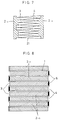
- the filter element 1 shown in Fig. 1 comprises a plurality of flat filters 5 arranged in parallel, end plates 6 alternately closing the inlet and outlet ends of the spaces between the adjacent filters 5, and liners 7 (which may be integral with the end plates 6) closing both sides of the spaces.
- the filters 5, end plates 6 and liners 7 define, in cooperation, alternating exhaust incoming spaces 3 and exhaust outgoing spaces 4.
- the filter element 11 shown in Fig. 2 comprises a plurality of untapered column-shaped (cylindrical in the example shown) filters 8 analogous in section with different diameters and arranged concentrically with each other, and end plates 6 alternately closing the inlet and outlet ends of the spaces between the adjacent filters, thereby defining the alternating exhaust incoming spaces 3 and exhaust outgoing spaces 4.
- the filter element 21 shown in Fig. 3 comprises a plurality of tapered column-shaped (conical in the example shown) filters 8 having different diameters from one another and arranged concentrically with the adjacent ones directed in opposite directions to each other so that the adjacent filters are connected together at their respective one and the other ends.
- the filter element has a zigzag section as a whole, as shown in Fig. 3B, with the alternating exhaust inlet spaces 3 and exhaust outlet spaces 4 defined between the adjacent filters 9.
- the filters of each of the filter elements 1, 11 and 12 are made of unwoven fabrics of metal fibers.
- the width of the spaces 3, 4 between the adjacent filters is preferably 10 mm or less.
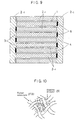
- the filter element of the embodiment shown in Fig. 4 may be any of the filter elements 1, 11 and 21 (though only the filter element 1 is shown in Fig. 1). It has air permeable reinforcing members 2-1 inserted in the exhaust outgoing spaces 4 to support the filters opposite to each other on both sides of each space 4.
- the filter element shown in Fig. 5 has reinforcing members 2-2 at both ends thereof. They have protrusions and recesses that engage both ends of the filters.
- the filter element shown in Fig. 6 has both the reinforcing members 2-1 and 2-2 shown in Figs. 4 and 5.
- the filter element shown in Fig. 7 has the same filters as those shown in Fig. 3, or has filters formed by bending flat filters in a zigzag manner so that they have the same section as the filters shown in Fig. 3B. Both sides of the spaces between filters are closed by liners. Reinforcing members 2-2 are provided at both ends of the filter element.
- the filter elements shown in Figs. 5, 6 and 7 have their filters in engagement with the recesses and protrusions of the reinforcing members 2-2 by arranging the dead ends of the spaces 3 and 4 in a staggered manner. But by using reinforcing members 2-2 having a suitable shape, it is possible to stably support the filters by bringing the filters into engagement with the protrusions and recesses of the reinforcing members without the need to stagger the dead ends of the spaces 3 and 4.
- the filter element of the embodiment shown in Fig. 8 may be any of the filter elements 1, 11 and 21 (though only the filter element 1 is shown). It has air permeable reinforcing members 2-1 and 2-3 inserted in the exhaust incoming spaces 3 and exhaust outgoing spaces 4, respectively, to support the filter element.
- the filter element shown in Fig. 9 is the same as the filter element shown in Fig. 8 with the reinforcing members 2-2 further added thereto.
- the reinforcing members 2-1 and 2-2 should be formed from a metal that will not deteriorate even when exposed to 700°C exhaust gases for 100 hours.
- metals include Fe-Cr-Al alloy and Ni-Cr-Al alloy, which are also used as filter materials.
- the reinforcing members should have a strength enough to withstand the pressure of 0.3 kg/cm 2 at 700°C.
- the metal filling rate cannot be reduced below a certain point, though this point depends on the kind of the metal used.
- the reinforcing members may be formed from a three-dimensionally reticulated porous member having a packing density of 30% or less, wire gauze, unwoven metal fabric, punching metal or corrugated sheet. If a corrugated sheet is used, the volume of a rectangular space in which the sheet fits tightly is regarded as the volume of the sheet.
- the reinforcing members 2-3 are also formed from a three-dimensionally reticulated porous member having a packing density of 30% or less, wire gauze, unwoven metal fabric, punching metal or corrugated sheet having a filling rate not exceeding 30%. If a corrugated sheet is used, the volume of a rectangular space in which the sheet fits tightly is regarded as the volume of the sheet.
- the filters may be made of meshed fibers (FB) with numerous fine alumina whiskers 401 added thereto to form multiplicity of minute pores.
- FB meshed fibers
- Fig. 11 is an enlarged view of the filters 1, 11 21. They may comprise a particulate trapping layer 301 made of a filter material, and a plurality of catalyst-carrying layers (such as layers 302 and 303).
- Fig. 12 shows an experiment device for evaluating the particulate trapping efficiency, the pressure drop when trapping particulates and the durability.
- This device comprises a 3400-cc, four-cylinder, direct-injection diesel engine car, a chassis dynamometer, and a dilution tunnel.
- Specimen I has a volume of 2.5 liters, which is the same as Specimens A and B.
- the reinforcing members used in Specimen A are formed by Ni-Cr-Al-alloying an Ni-based, three-dimensionally reticulated porous material (trade name: cermet #1) made by Sumitomo Electric Industries, Ltd.
- Particulate traps 10 formed by placing these specimens in cases are mounted in the device shown in Fig. 12 to check how the filter elements were destroyed when high-temperature exhausts are passed for a long time. The results are shown in Table 3.
- Specimens A and B were not destroyed, Specimen I suffered cracks.
- the particulate trapping capacity, and trapping properties such as increase in the pressure difference (pressure drop) after particulates are trapped. But no significant difference in these properties was observed among these three specimens.
- Table 5 shows detailed data on these specimens.
- Table 6 shows the detailed data on the reinforcing members 2-1 and 2-2 used in Specimen C.
- Table 7 shows the results of an endurance test conducted for each specimen in the same manner as in EXPERIMENT 1.
- Table 9 shows detailed data on these specimens.
- Table 10 shows the detailed data on the reinforcing members 2-1 and 2-2 used in Specimen E.
- test results are exactly the same as the results in Embodiments 1 and 2. That is, only the example of the invention, i.e. Specimen E, achieved good results in all of the particulate trapping properties, durability and regenerating properties.
- Tables 13 and 14 show more detailed data on these specimens and the reinforcing members 2-2 used in Specimen G.
- test results are exactly the same as the results in EXPERIMENT 1, 2 and 3.
- particulate trapping properties no significant difference was observed among the specimens.
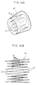
- the filter element 31 shown in Fig. 13 is an improved version of the filter element shown in Fig. 2.
- the filter element 41 shown in Fig. 14 is an improvement of the filter element shown in Fig. 3.
- These filter elements 31 and 41 comprise a plurality of groups of concentrically arranged cylindrical filters, each group comprising several adjacent filters having the same thickness which is larger than the thicknesses of the smaller-diameter filters of the inner filter group. But it is more preferable that each cylindrical filter has a larger thickness than the inner, smaller-diameter filters.
- J filter elements comprising 11 cylindrical filters having different diameters and arranged concentrically with one another as shown in Fig. 13, the filters having thicknesses increasing outwardly in five stages.
- Table 17 shows detailed data on these specimens.
- Specimen I had a volume of 2.5 liters, which is the same volume as Specimens J and K.
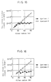
- Fig. 15 shows the relationship between the maximum stress applied to the cylindrical filter of each of Specimens J and K due to the initial exhaust pressure and the filter diameter.
- Particulate traps 10 formed by placing these specimens J. K and I in cases are mounted in the exhaust line of the device shown in Fig. 12 to check how the filter elements were destroyed when high-temperature exhausts were passed for a long time. The results are shown in Table 19.
- Table 21 shows more detailed data on each specimen.
- Table 22 shows the pressures at which Specimens L and M buckled.
- Fig. 16 shows the relationship between the maximum stress applied to each filter of the specimen due to the initial exhaust pressure and the filter diameter.
- Tables 23 and 24, respectively, show the results of an endurance test conducted in the same manner as in EXPERIMENT 5, and an endurance test during regeneration conducted in the same manner as in Embodiment 1, for Specimens L, M and I.
- Specimen I has a volume of 2.5 liters, i.e. the same volume as Specimens N, O and P.
- the reinforcing members used in Specimens N and O are formed by Ni-Cr-Al-alloying an Ni-based, three-dimensionally reticulated porous material (trade name: cermet #1) made by Sumitomo Electric Industries, Ltd.
- the filter element 1 of Specimen N comprises a NOx catalyst-carrying layer (302 in Fig. 11), a particulate trapping layer (301 in Fig. 11), and a NOx catalyst-carrying layer (303 in Fig. 11).
- Each NOx catalyst layer comprises a substrate of Fe-Cr-Al unwoven metal fabric, a catalyst-carrying ⁇ -alumina coating provided on the unwoven metal fabric at the rate of 100 grams per liter of unwoven metal fabric, and Cu as a catalyst uniformly carried on the ⁇ -alumina coating at the rate of 1.0 gram per liter of unwoven metal fabric.
- the reinforcing members (2-1 in Fig. 4) of Specimen O has a NOx catalyst-carrying ⁇ -alumina coating on the cermet substrate at the rate of 100 grams per liter of cermet, and Cu as a catalyst uniformly carried on the ⁇ -alumina coating at the rate of 1.0 gram/liter.
- the NO concentration was measured for two minutes while keeping the exhaust temperature at 250°C.
- Table 30 shows the average NO concentration.
- Table 31 shows detailed data on these specimens.
- Table 32 shows the details for the reinforcing members 2-1, 2-2 used for Specimens Q and R.
- Specimen I has a volume of 2.5 liters, i.e. the same volume as Specimens Q, R and S.
- the filter element 11 of Specimen Q comprises an SOF catalyst-carrying layer (302 in Fig. 11), a particulate trapping layer (301 in Fig. 11), and another SOF catalyst-carrying layer (303 in Fig. 11).
- Each SOF catalyst layer comprises a substrate of Fe-Cr-Al unwoven metal fabric, a catalyst-carrying ⁇ -alumina coating provided on the unwoven metal fabric at the rate of 150 grams per liter of unwoven metal fabric, and Pt as a catalyst uniformly carried on the ⁇ -alumina coating at the rate of 1.5 grams/liter.
- the reinforcing members (2-1 in Fig. 6) of Specimen R has an SOF catalyst-carrying ⁇ -alumina coating on the cermet substrate at the rate of 150 grams per liter of cermet, and Pt as a catalyst uniformly carried on the ⁇ -alumina coating at the rate of 1.5 grams/liter.
- Specimens Q and R according to the invention achieved satisfactory results in all of the particulate trapping properties, durability and regenerating properties.
- the SOF concentration decreased by 40% or 50%.
- Table 36 shows detailed data on these specimens.
- Table 37 shows detailed data on the reinforcing members 2-1, 2-2 and 2-3 used in Specimens T and U.
- Specimen I has a volume of 2.5 liters, i.e. the same volume as Specimens T, U and V.
- the reinforcing members (2-1 and 2-3 in Fig. 8) of Specimen T has a NOx catalyst-carrying ⁇ -alumina coating on the cermet substrate at the rate of 100 grams per liter of cermet, and Cu as a catalyst uniformly carried on the ⁇ -alumina coating at the rate of 1.0 grams/liter.
- the reinforcing members (2-1 and 2-3 in Fig. 8) of Specimen U has an SOF catalyst-carrying ⁇ -alumina coating on the unwoven metal fabric substrate at the rate of 150 grams per liter of unwoven fabric, and Pt as a catalyst uniformly carried on the ⁇ -alumina coating at the rate of 1.5 grams/liter.
- Specimens T and U according to the invention achieved satisfactory results in all of the particulate trapping properties, durability and regenerating properties.
- the NO concentration was measured for two minutes while keeping the exhaust temperature at 250°C.
- Table 41 shows the average concentration.
Landscapes
- Chemical & Material Sciences (AREA)
- Physics & Mathematics (AREA)
- Geometry (AREA)
- Chemical Kinetics & Catalysis (AREA)
- Engineering & Computer Science (AREA)
- Mechanical Engineering (AREA)
- Combustion & Propulsion (AREA)
- General Engineering & Computer Science (AREA)
- Health & Medical Sciences (AREA)
- Toxicology (AREA)
- Processes For Solid Components From Exhaust (AREA)
- Filtering Materials (AREA)
- Filtering Of Dispersed Particles In Gases (AREA)
Description
| Filter element | Filter area | ||||
| Material | Material | Thickness | Packing density | ||
| Specimen A (Invented) | Unwoven metal fabrics (fiber 20µm dia) | Fe-Cr-Al | 0.5 mm | 20 % | 1.3m2 |
| Specimen B (Invented) | Unwoven metal fabrics (fiber 20µm dia) | Fe-Cr-Al | 0.5 mm | 20 % | 1.3m2 |
| Specimen I (Comparative) | Cordierite | MgO-Al2O3-SiO2 | 0.5 mm | 50 % | 2.3m2 |
| Material | Material | Packing density | Heat resistance | Strength | |
| Reinforcing member of Specimen A | cermet | Ni-Cr-Al | 5 % | No deterioration when exposed to exhaust at 700°C for 100 hours | No breakage under pressure of 0.3kg/cm2 by exhaust at 700°C |
| Specimen | Results of endurance test (Temperature of exhaust at trap inlet: 700°C) |
| Specimen A | No breakage after 150 hours |
| Specimen B | Breakage noticed after 120 hours |
| Specimen C | No breakage after 150 hours |
| Regeneration test result | |
| Specimen A (Invented) | Not broken |
| Specimen B (Comparative) | Not broken |
| Specimen I (Comparative) | Crack formed |
| Filter element | Filter area | ||||
| Material | Material | Thickness | Packing density | ||
| Specimen C (Invented) | Unwoven metal fabrics (fiber 20µm dia) | Fe-Cr-Al | 0.5 mm | 20 % | 1.3m2 |
| Specimen D (Comparative) | Unwoven metal fabrics (fiber 20µm dia) | Fe-Cr-Al | 0.5 mm | 20 % | 1.3m2 |
| Specimen I (Comparative) | Cordierite | MgO-Al2O3-SiO2 | 0.5 mm | 50 % | 2.3m2 |
| Material | Material | Packing density | Heat resistance | Strength | |
| Reinforcing member 2-1 | wire gauge | Fe-Cr-Al | 20 % | No deterioration when exposed to exhaust at 700°C for 100 hours | No breakage under pressure of 0.3kg/cm2 by exhaust at 700°C |
| Reinforcing member 2-2 | cermet | Ni-Cr-Al | 5 % | No deterioration when exposed to exhaust at 700°C for 100 hours | No breakage under pressure of 0.3kg/cm2 by exhaust at 700°C |
| Specimen | Results of endurance test (Temperature of exhaust at trap inlet: 800°C) |
| Specimen C | No breakage after 120 hours |
| Specimen D | Breakage noticed after 100 hours |
| Specimen I | No breakage after 120 hours |
| Regeneration test result | |
| Specimen C (Invented) | Not broken |
| Specimen D (Comparative) | Not broken |
| Specimen I (Comparative) | Crack formed |
| Filter element | Filter area | ||||
| Material | Material | Thickness | Packing density | ||
| Specimen E (Invented) | Unwoven metal fabrics (fiber 20µm dia) | Fe-Cr-Al | 0.5 mm | 20 % | 1.3m2 |
| Specimen F (Comparative) | Unwoven metal fabrics (fiber 20µm dia) | Fe-Cr-Al | 0.5 mm | 20 % | 1.3m2 |
| Specimen I (Comparative) | Cordierite | MgO-Al2O3-SiO2 | 0.5 mm | 50 % | 2.3m2 |
| Material | Material | Packing density | Heat resistance | Strength | |
| Reinforcing member 2-1 | cermet #2 gauge | Ni-Cr-Al | 5 % | No deterioration when exposed to exhaust at 700°C for 100 hours | No breakage under pressure of 0.3kg/cm2 by exhaust at 700°C |
| Reinforcing member 2-2 | punching metal | Fe-Cr-Al | 15 % | No deterioration when exposed to exhaust at 700°C for 100 hours | No breakage under pressure of 0.3kg/cm2 by exhaust at 700°C |
| Specimen | Results of endurance test (Temperature of exhaust at trap inlet: 800°C) |
| Specimen E | No breakage after 120 hours |
| Specimen F | Breakage noticed after 100 hours |
| Specimen I | No breakage after 120 hours |
| Regeneration test result | |
| Specimen E (Invented) | Not broken |
| Specimen F (Comparative) | Not broken |
| Specimen I (Comparative) | Crack formed |
| Filter element | Filter area | ||||
| Material | Material | Thickness | Packing density | ||
| Specimen G (Invented) | Unwoven metal fabrics (fiber dia 40µm at inlet 20µm at outlet) | Fe-Cr-Al | 0.5 mm | 20 % | 1.3m2 |
| Specimen H (Comparative) | Unwoven metal fabrics (fiber dia 40µm at inlet 20µm at outlet) | Fe-Cr-Al | 0.5 mm | 20 % | 1.1m2 |
| Specimen I (Comparative) | Cordierite | MgO-Al2O3-SiO2 | 0.5 mm | 50 % | 2.3m2 |
| Material | Material | Packing density | Heat resistance | Strength | |
| Reinforcing member of Specimen A | cermet #1 | Ni-Cr-Al | 5 % | No deterioration when exposed to exhaust at 700°C for 100 hours | No breakage under pressure of 0.3kg/cm2 by exhaust at 700°C |
| Specimen | Results of endurance test (Temperature of exhaust at trap inlet: 700°C) |
| Specimen G | No breakage after 150 hours |
| Specimen H | Breakage noticed after 120 hours |
| Specimen I | No breakage after 150 hours |
| Regeneration test result | |
| Specimen G (Invented) | Not broken |
| Specimen H (Comparative) | Not broken |
| Specimen I (Comparative) | Crack formed |
| Filter element | Filter area | |||||
| Material | Material | Thickness | Packing density | Filter element used | ||
| Specimen J | Unwoven metal fabrics(1) (fiber dia 50 µm at inlet 35µm at outlet) | Fe-Cr-Al | 0.4 mm | 20 % | cylindrical 10 and 15 mm radius | 1.1m2 |
| Unwoven metal fabrics(2) (fiber dia 35 µm at inlet 25µm at outlet) | Fe-Cr-Al | 0.6 mm | 20 % | cylindrical 20 and 25 mm radius | ||
| Unwoven metal fabrics(3) (fiber dia 25 µm at inlet 20µm at outlet) | Fe-Cr-Al | 0.8 mm | 20 % | cylindrical 30 and 35 mm radius | ||
| Unwoven metal fabrics(4) (fiber dia 20 µm at inlet 15µm at outlet) | Fe-Cr-Al | 1.0 mm | 20 % | cylindrical 40 and 45 mm radius | ||
| Unwoven metal fabrics(5) (fiber dia 15 µm at inlet 10µm at outlet) | Fe-Cr-Al | 1.2 mm | 20 % | cylindrical 50,55 and 60 mm radius | ||
| Specimen K (Comparative) | Unwoven metal fabrics(6) (fiber dia 40 µm at inlet 30µm at outlet) | Fe-Cr-Al | 0.5 mm | 20 % | all filter elements | 1.1m2 |
| Specimen I (Comparative) | Cordierite | MgO-Al2O3-SiO2 | 0.5 mm | 50 % | all filter elements | 2.3m2 |
| Pressure at which buckling occured (in KPa) | |
| Specimen J | 200 |
| Specimen K (Comparative) | 40 |
| Specimen | Results of endurance test (Temperature of exhaust at trap inlet: 800°C) |
| Specimen J | No breakage after 150 hours |
| Specimen K | Breakage noticed after 100 hours |
| Specimen I | No breakage after 150 hours |
| Regeneration test result | |
| Specimen J | Not broken |
| Specimen K (Comparative) | Not broken |
| Specimen I (Comparative) | Crack formed |
| Filter element | Filter area | |||||
| Material | Material | Thickness | Packing density | Filter element used | ||
| Specimen L | Unwoven metal fabrics (1) (fiber dia 40µm at inlet 30µm at outlet) | Fe-Cr-Al | 0.5 mm | 20 % | tapered elements | 1.2m2 |
| 1) 0×20mm radius | ||||||
| 2)20×30mm radius | ||||||
| Unwoven metal fabrics (2) (fiber dia 20µm at inlet 15µm at outlet) | Fe-Cr-Al | 1.0 mm | 20 % | tapered elements | ||
| 1)30×40mm radius | ||||||
| 2)40×50mm radius | ||||||
| 3)50×60mm radius | ||||||
| Unwoven metal fabrics (3) (fiber dia 15µm at inlet 10µm at outlet) | Fe-Cr-Al | 1.5 mm | 20 % | tapered elements | ||
| 1)60×70mm radius | ||||||
| 2)70×80mm radius | ||||||
| 3)80×90mm radius | ||||||
| Specimen M (Comparative) | Unwoven metal fabrics (1) (fiber dia 40µm at inlet 20µm at outlet) | Fe-Cr-Al | 0.5 mm | 20 % | all filter elements | 1.1m2 |
| Specimen I (Comparative) | Cordierite | MgO-Al2O3-SiO2 | 0.5 mm | 50 % | all filter elements | 2.3m2 |
| Pressure at which buckling occured (in KPa) | |
| Specimen L | 140 |
| Specimen M (Comparative) | 15 |
| Specimen | Results of endurance test (Temperature of exhaust at trap inlet: 800°C) |
| Specimen L | No breakage after 120 hours |
| Specimen M | Breakage noticed after 100 hours |
| Specimen I | No breakage after 120 hours |
| Regeneration test result | |
| Specimen L | Not broken |
| Specimen M (Comparative) | Not broken |
| Specimen I (Comparative) | Crack formed |
| Filter element | Filter area | ||||
| Material | Material | Thickness | Packing density | ||
| Specimen N (Invented) | (1) Unwoven metal fabrics (fiber dia 100µm) +γ-Al2O3+Cu | (1) Fe-Cr-Al+ γ-Al2O3+Cu | 1.0 mm | 20 % | 1.3m2 |
| (2) Unwoven metal fabrics (fiber dia 20µm) | (2) Fe-Cr-Al | ||||
| (3) Unwoven metal fabrics (fiber dia 100µm) +γ-Al2O3+Cu | (3) Fe-Cr-Al+ γ-Al2O3+Cu | ||||
| Specimen O (Invented) | Unwoven metal fabrics (fiber dia 20µm) | Fe-Cr-Al | 1.0 mm | 20 % | 1.3m2 |
| Specimen P (Comparative) | Unwoven metal fabrics (fiber dia 20µm) | Fe-Cr-Al | 1.0 mm | 20 % | 1.3m2 |
| Specimen I (Comparative) | Cordierite | MgO-Al2O3-SiO2 | 1.0 mm | 50 % | 2.3m2 |
| Material | Material | Packing density | Heat resistance | Strength | |
| Reinforcing member of Specimen N | cermet | Ni-Cr-Al | 5 % | No deterioration when exposed to exhaust at 700°C for 100 hours | No breakage under pressure of 0.3kg/cm2 by exhaust at 700°C |
| Reinforcing member of Specimen O | cermet | Ni-Cr-Al +γ-Al2O3 +Cu | 5 % | No deterioration when exposed to exhaust at 700°C for 100 hours | No breakage under pressure of 0.3kg/cm2 by exhaust at 700°C |
| Specimen | Results of endurance test (Temperature of exhaust at trap inlet: 700°C) |
| Specimen N | No breakage after 150 hours |
| Specimen O | No breakage after 150 hours |
| Specimen F | Breakage noticed after 120 hours |
| Specimen I | No breakage after 150 hours |
| Regeneration test result | |
| Specimen N | Not broken |
| Specimen O | Not broken |
| Specimen P | Not broken |
| Specimen I | Crack formed |
| Item | Condition |
| NO concentration in exhausts | 1000 ppm |
| C2H4 concentration in exhausts | 250 ppm |
| O2 concentration in exhausts | 2 % |
| Exhaust temperature | 250 °C |
| NO concentration | |
| Specimen N | 500 ppm |
| Specimen O | 500 ppm |
| Filter element | Filter area | ||||
| Material | Material | Thickness | Packing density | ||
| Specimen Q (Invented) | (1) Unwoven metal fabrics (fiber dia 100µm) +γ-Al2O3+Cu | (1) Fe-Cr-Al+ γ-Al2O3+Pt | 1.0 mm | 20 % | 1.3m2 |
| (2) Unwoven metal fabrics (fiber dia 20µm) | (2) Fe-Cr-Al | ||||
| (3) Unwoven metal fabrics (fiber dia 100µm) +γ-Al2O3+Cu | (3) Fe-Cr-Al+ γ-Al2O3+Pt | ||||
| Specimen R (Invented) | Unwoven metal fabrics (fiber dia 20µm) | Fe-Cr-Al | 1.0 mm | 20 % | 1.3m2 |
| Specimen S (Comparative) | Unwoven metal fabrics (fiber dia 20µm) | Fe-Cr-Al | 1.0 mm | 20 % | 1.3m2 |
| Specimen I (Comparative) | Cordierite | MgO-Al2O3-SiO2 | 1.0 mm | 50 % | 2.3m2 |
| Material | Material | Packing density | Heat resistance | Strength | |
| Reinforcing member 2-1 of Specimen Q | wire gauge | Fe-Cr-Al | 20 % | No deterioration when exposed to exhaust at 700°C for 100 hours | No breakage under pressure of 0.3kg/cm2 by exhaust at 700°C |
| Reinforcing member 2-2 of Specimen Q | cermet | Ni-Cr-Al | 5 % | No deterioration when exposed to exhaust at 700°C for 100 hours | No breakage under pressure of 0.3kg/cm2 by exhaust at 700°C |
| Reinforcing member 2-1 of Specimen R | wire gauge | Fe-Cr-Al | 20 % | No deterioration when exposed to exhaust at 700°C for 100 hours | No breakage under pressure of 0.3kg/cm2 by exhaust at 700°C |
| Reinforcing member 2-2 of Specimen R | cermet | Ni-Cr-Al +γ-Al2O3 +Pt | 5 % | No deterioration when exposed to exhaust at 700°C for 100 hours | No breakage under pressure of 0.3kg/cm2 by exhaust at 700°C |
| Specimen | Results of endurance test (Temperature of exhaust at trap inlet: 800°C) |
| Specimen Q | No breakage after 150 hours |
| Specimen R | No breakage after 150 hours |
| Specimen S | Breakage noticed after 120 hours |
| Specimen I | No breakage after 150 hours |
| Regeneration test result | |
| Specimen Q | Not broken |
| Specimen R | Not broken |
| Specimen S | Not broken |
| Specimen I | Crack formed |
| SOF removing rate (%) | ||
| Exhaust temperature 250°C | Exhaust temperature 350°C | |
| Specimen Q | 40 | 50 |
| Specimen R | 40 | 50 |
| Filter element | Filter area | ||||
| Material | Material | Thickness | Packing density | ||
| Specimen T (Invented) | Unwoven metal fabrics (fiber 20µm dia) | Fe-Cr-Al | 0.5 mm | 20 % | 1.3m2 |
| Specimen U (Invented) | Unwoven metal fabrics (fiber 20µm dia) | Fe-Cr-Al | 0.5 mm | 20 % | 1.3m2 |
| Specimen V (Comparative) | Unwoven metal fabrics (fiber 20µm dia) | Fe-Cr-Al | 0.5 mm | 20 % | 1.3m2 |
| Specimen I (Comparative) | Cordierite | MgO-Al2O3-SiO2 | 0.5 mm | 50 % | 2.3m2 |
| Material | Material | Packing density | Heat resistance | Strength | |
| Reinforcing member 2-1, 2-3 of Specimen T | cermet | Fe-Cr-Al +γ-Al2O3 +Cu | 5 % | No deterioration when exposed to exhaust at 700°C for 100 hours | No breakage under pressure of 0.3kg/cm2 by exhaust at 700°C |
| Reinforcing member 2-1, 2-3 of Specimen U | cermet | Ni-Cr-Al +γ-Al2O3 +Pt | 5 % | No deterioration when exposed to exhaust at 700°C for 100 hours | No breakage under pressure of 0.3kg/cm2 by exhaust at 700°C |
| Specimen | Results of endurance test (Temperature of exhaust at trap inlet: 700°C) |
| Specimen T | No breakage after 150 hours |
| Specimen U | No breakage after 150 hours |
| Specimen V | Breakage noticed after 120 hours |
| Specimen I | No breakage after 150 hours |
| Regeneration test result | |
| Specimen T | Not broken |
| Specimen U | Not broken |
| Specimen V | Not broken |
| Specimen I | Crack formed |
| Item | Condition |
| NO concentration in exhausts | 1000 ppm |
| C2H4 concentration in exhausts | 250 ppm |
| O2 concentration in exhausts | 2 % |
| Exhaust temperature | 250 °C |
| NO concentration | |
| Specimen T | 500 ppm |
| SOF removing rate (%) | ||
| Exhaust temperature 250°C | Exhaust temperature 350°C | |
| Specimen U | 40 | 50 |
Claims (10)
- A particulate trap for use in a diesel engine including a filter element (1, 11, 21) comprising a plurality of filters (5, 8, 9) made of unwoven fabrics of metal fibers, said filters defining alternating, longitudinally extending exhaust incoming spaces (3) and exhaust outgoing spaces (4) between said adjacent filters (5, 8, 9), said exhaust incoming spaces (3) having their outlet ends closed, said exhaust outgoing spaces (4) having their inlet ends closed, said filter element (1, 11, 21) being mounted in a container provided in an exhaust line of a diesel engine,
characterized in that
filter reinforcing members (2-1, 2-2) permeable to exhaust gases are provided in said exhaust outgoing spaces (4), at both ends of said filters, or both in said exhaust outgoing spaces (4) and at both ends of said filters, wherein the reinforcing members (2-1) provided in said exhaust outgoing spaces (4) occupy the entire exhaust outgoing spaces (4). - A particulate trap for a diesel engine as claimed in claim 1 wherein filter reinforcing members (2-3) permeable to exhaust gases are provided in said exhaust incoming spaces (3).
- A particulate trap for a diesel engine as claimed in claim 2 wherein said reinforcing members (2-3) provided in said exhaust incoming spaces (3) occupy the entire area of said exhaust incoming spaces (3).
- A particulate trap for a diesel engine as claimed in claim 1 wherein said reinforcing members (2-2) provided at both ends of said filters (5, 8, 9) have protrusions and recesses kept in engagement with both ends of said filters.
- A particulate trap for a diesel engine as claimed in any of claims 1-4 wherein said reinforcing members (2-1, 2-2, 2-3) have a material filling rate of 30% or less and is made of a heat-resistant metal in the form of a three-dimensionally reticulated porous member, wire gauze, metal fiber unwoven fabric, corrugated sheet or punching metal.
- A particulate trap as claimed in any of claims 1-5 wherein said each filter (5, 8, 9) is made of at least two different kinds of filter materials having different pore diameters, the filter material having a larger pore diameter being provided nearer to the exhaust inlet side.
- A particulate trap for diesel engine use as claimed in any of claims 1-6 wherein exhaust inlets and outlets defined between said filters have a width not exceeding 10mm.
- A particulate trap for a diesel engine as claimed in any of claims 1-7 wherein a catalyst is carried on one or either side of said each filter of said filter element.
- A particulate trap for a diesel engine as claimed in any of claims 1-8 wherein said each filter of said filter element is provided on one or either side thereof with a three-dimensionally reticulated porous member made of a heat-resistant metal and having continuous holes, said three-dimensionally reticulated porous member carrying a catalyst.
- A particulate trap for a diesel engine as claimed in any of claims 1-9 wherein alumina whiskers are grown on said filters of said filter element.
Applications Claiming Priority (6)
| Application Number | Priority Date | Filing Date | Title |
|---|---|---|---|
| JP13181095 | 1995-05-30 | ||
| JP131810/95 | 1995-05-30 | ||
| JP13181095 | 1995-05-30 | ||
| JP09811896A JP3378432B2 (en) | 1995-05-30 | 1996-04-19 | Particulate trap for diesel engine |
| JP98118/96 | 1996-04-19 | ||
| JP9811896 | 1996-04-19 |
Publications (3)
| Publication Number | Publication Date |
|---|---|
| EP0745759A2 EP0745759A2 (en) | 1996-12-04 |
| EP0745759A3 EP0745759A3 (en) | 1997-03-05 |
| EP0745759B1 true EP0745759B1 (en) | 2000-08-30 |
Family
ID=26439322
Family Applications (1)
| Application Number | Title | Priority Date | Filing Date |
|---|---|---|---|
| EP96108020A Expired - Lifetime EP0745759B1 (en) | 1995-05-30 | 1996-05-20 | Particulate trap for diesel engine |
Country Status (4)
| Country | Link |
|---|---|
| US (1) | US5863311A (en) |
| EP (1) | EP0745759B1 (en) |
| JP (1) | JP3378432B2 (en) |
| DE (1) | DE69610019T2 (en) |
Families Citing this family (41)
| Publication number | Priority date | Publication date | Assignee | Title |
|---|---|---|---|---|
| US20030135971A1 (en) * | 1997-11-12 | 2003-07-24 | Michael Liberman | Bundle draw based processing of nanofibers and method of making |
| US6056796A (en) * | 1998-02-09 | 2000-05-02 | The United States Of America As Represented By The United States Department Of Energy | Rigid porous filter |
| US6776814B2 (en) | 2000-03-09 | 2004-08-17 | Fleetguard, Inc. | Dual section exhaust aftertreatment filter and method |
| US6669913B1 (en) | 2000-03-09 | 2003-12-30 | Fleetguard, Inc. | Combination catalytic converter and filter |
| US7211226B2 (en) * | 2000-03-09 | 2007-05-01 | Fleetgaurd, Inc. | Catalyst and filter combination |
| US7052532B1 (en) | 2000-03-09 | 2006-05-30 | 3M Innovative Properties Company | High temperature nanofilter, system and method |
| US6568178B2 (en) * | 2000-03-28 | 2003-05-27 | Toyota Jidosha Kabushiki Kaisha | Device for purifying the exhaust gas of an internal combustion engine |
| DE10035544B4 (en) * | 2000-07-21 | 2012-01-05 | Daimler Ag | Filter arrangement for an emission control system |
| CN1201070C (en) * | 2000-07-24 | 2005-05-11 | 丰田自动车株式会社 | Exhaust emission purifying device of internal combustion engine |
| DE60115479T2 (en) * | 2000-09-20 | 2006-07-20 | Toyota Jidosha K.K., Toyota | FILTER AND METHOD FOR CONTROLLING THE EXHAUST EMISSIONS |
| JP2002102621A (en) * | 2000-09-28 | 2002-04-09 | Matsushita Electric Ind Co Ltd | Exhaust gas purifying material and method for producing the same |
| WO2002094413A1 (en) * | 2001-05-22 | 2002-11-28 | Pall Corporation | Advanced leaf disc filter segment |
| US6544310B2 (en) * | 2001-05-24 | 2003-04-08 | Fleetguard, Inc. | Exhaust aftertreatment filter with particulate distribution pattern |
| JP2002371823A (en) * | 2001-06-19 | 2002-12-26 | Mitsui Eng & Shipbuild Co Ltd | Diesel engine exhaust gas purification equipment |
| CN1285829C (en) * | 2001-08-08 | 2006-11-22 | 丰田自动车株式会社 | An exhaust gas purification device |
| US7141088B2 (en) * | 2001-08-08 | 2006-11-28 | Toyota Jidosha Kabushiki Kaisha | Exhaust gas purifying apparatus |
| US20030101718A1 (en) * | 2001-10-06 | 2003-06-05 | Marcus Pfeifer | Method and device for the catalytic conversion of gaseous pollutants in the exhaust gas of combustion engines |
| SE520972C2 (en) * | 2001-12-06 | 2003-09-16 | Stt Emtec Ab | Device for cleaning its exhaust gases in an internal combustion engine |
| US20040116276A1 (en) * | 2002-02-12 | 2004-06-17 | Aleksey Yezerets | Exhaust aftertreatment emission control regeneration |
| US20030155293A1 (en) * | 2002-02-21 | 2003-08-21 | Mcgrath James A. | Square-holed spiral welded filter element support sleeve |
| US6866693B2 (en) * | 2002-06-06 | 2005-03-15 | Shuetsutechnica Co., Ltd. | Washable air filter for internal combustion engine |
| JP3719232B2 (en) * | 2002-06-18 | 2005-11-24 | トヨタ自動車株式会社 | Particulate filter for internal combustion engine |
| DE10235766A1 (en) * | 2002-08-02 | 2004-02-19 | Emitec Gesellschaft Für Emissionstechnologie Mbh | Exhaust gas filter, for treating motor exhaust, has structured layers with initial short contact zone with catalyst action to convert gas components, and filter zone to retain particles without additional upstream catalyst |
| KR100692356B1 (en) | 2003-07-15 | 2007-03-12 | 이비덴 가부시키가이샤 | Honeycomb structure |
| US7191592B2 (en) * | 2004-06-28 | 2007-03-20 | Corning Incorporated | Diesel engine exhaust system |
| JP4649587B2 (en) * | 2004-06-29 | 2011-03-09 | 独立行政法人産業技術総合研究所 | Exhaust gas purification filter and collection method of particulate matter |
| US7225613B2 (en) * | 2005-01-26 | 2007-06-05 | Ford Global Technologies, Llc | Diesel engine after treatment device for conversion of nitrogen oxide and particulate matter |
| US8615988B2 (en) * | 2005-08-23 | 2013-12-31 | GM Global Technology Operations LLC | Electrical diesel particulate filter (DPF) regeneration |
| DE102006009164B4 (en) * | 2006-02-20 | 2011-06-09 | Alantum Corporation, Seongnam | Device for the separation of particles contained in exhaust gases of internal combustion engines |
| US20070220856A1 (en) * | 2006-03-23 | 2007-09-27 | Fiber Tech Co., Ltd. | Metal fiber media, filter for exhaust gas purifier using the same as filter member, and method for manufacturing the filter |
| US7753978B2 (en) | 2006-06-30 | 2010-07-13 | Caterpillar Inc | Filter system |
| US7967887B1 (en) | 2006-11-03 | 2011-06-28 | Cummins Filtration Ip, Inc. | Exhaust aftertreatment filter with reduced maximum temperature |
| JP2009011921A (en) * | 2007-07-04 | 2009-01-22 | Tanaka Kikinzoku Kogyo Kk | Diesel exhaust gas purification filter |
| US7806956B2 (en) * | 2007-08-09 | 2010-10-05 | Cummins Filtration Ip, Inc. | Tuning particulate filter performance through selective plugging and use of multiple particulate filters to reduce emissions and improve thermal robustness |
| US8297223B2 (en) * | 2007-10-02 | 2012-10-30 | Msp Corporation | Method and apparatus for particle filtration and enhancing tool performance in film deposition |
| DE102007058791B4 (en) * | 2007-12-06 | 2019-08-29 | Emcon Technologies Germany (Augsburg) Gmbh | Exhaust treatment device |
| DE102009010307A1 (en) * | 2009-02-24 | 2010-08-26 | Daimler Ag | Exhaust gas treatment device and method for operating an exhaust gas treatment device |
| US8312712B2 (en) * | 2009-06-29 | 2012-11-20 | GM Global Technology Operations LLC | Electrically heated particulate filter regeneration during engine start/stop operation |
| JP7120876B2 (en) * | 2018-10-17 | 2022-08-17 | 日本碍子株式会社 | honeycomb structure |
| JP7034376B2 (en) * | 2019-03-22 | 2022-03-11 | 日本碍子株式会社 | Honeycomb structure and exhaust gas purification device |
| CA3137990A1 (en) * | 2019-06-21 | 2020-12-24 | Climeworks Ag | Adsorber structure for gas separation processes |
Citations (1)
| Publication number | Priority date | Publication date | Assignee | Title |
|---|---|---|---|---|
| WO1989002976A1 (en) * | 1987-09-22 | 1989-04-06 | Frenzelit-Werke Gmbh & Co. Kg | Soot filter |
Family Cites Families (21)
| Publication number | Priority date | Publication date | Assignee | Title |
|---|---|---|---|---|
| BE446170A (en) * | 1939-06-28 | |||
| JPS54110189A (en) * | 1978-02-17 | 1979-08-29 | Ngk Insulators Ltd | Ceramic honeycomb structure |
| CH635654A5 (en) * | 1978-08-16 | 1983-04-15 | Cesare Balzi | Emission control unit for exhaust gases |
| US4363644A (en) * | 1980-02-04 | 1982-12-14 | Nippon Soken, Inc. | Filter for purifying exhaust gas |
| JPS57113822A (en) * | 1980-12-30 | 1982-07-15 | Nippon Soken Inc | Fine particle collecting filter |
| JPS5845715A (en) * | 1981-09-14 | 1983-03-17 | Ngk Insulators Ltd | Ceramic honeycomb filter |
| JPS58137423A (en) * | 1982-02-09 | 1983-08-15 | Ngk Spark Plug Co Ltd | Filter apparatus for exhaust gas |
| JPS5928010A (en) * | 1982-08-05 | 1984-02-14 | Nippon Denso Co Ltd | Structure to purify exhaust gas |
| JPS6142616A (en) * | 1984-08-03 | 1986-03-01 | Hamamatsu Photonics Kk | Fresnel zone plate by acousto-optical element |
| JPS62149316A (en) * | 1985-12-24 | 1987-07-03 | Matsushita Electric Ind Co Ltd | exhaust gas filter |
| JP2675071B2 (en) * | 1988-05-31 | 1997-11-12 | イビデン株式会社 | Honeycomb filter |
| DE4012719A1 (en) * | 1990-04-21 | 1991-10-24 | Roggenkamp Karl Heinz | Engine esp. diesel engine exhaust gas purificn. by complete filtration - with gas permeable filter of refractory fibres to remove solid particles, e.g. soot |
| DE4024215A1 (en) * | 1990-07-31 | 1992-02-06 | Didier Werke Ag | FILTER APPARATUS |
| DE4106303A1 (en) * | 1991-02-28 | 1992-09-03 | Drache Keramikfilter | HIGH TEMPERATURE GAS FILTERS, ESPECIALLY DIESEL SOOT FILTERS |
| JPH04339120A (en) * | 1991-05-15 | 1992-11-26 | Nippon Soken Inc | Exhaust gas particulate purifing device for internal combustion engine |
| DE4130629A1 (en) * | 1991-09-14 | 1993-03-18 | Kloeckner Humboldt Deutz Ag | ELECTRICALLY REGENERABLE PARTICLE FILTER IN MODULAR CANDLE SHAPE |
| WO1994006538A1 (en) * | 1992-09-14 | 1994-03-31 | Sumitomo Electric Industries, Ltd. | Exhaust gas cleaning filter medium and method of manufacturing the same |
| JPH06257422A (en) * | 1993-01-06 | 1994-09-13 | Sumitomo Electric Ind Ltd | Particulate trap for diesel engine |
| JP3265737B2 (en) * | 1993-08-20 | 2002-03-18 | 住友電気工業株式会社 | High corrosion resistant metal filter |
| JPH07112135A (en) * | 1993-08-23 | 1995-05-02 | Sumitomo Electric Ind Ltd | Exhaust gas purification filter material and manufacturing method thereof |
| JPH0949421A (en) * | 1995-05-30 | 1997-02-18 | Sumitomo Electric Ind Ltd | Particulate trap for diesel engine |
-
1996
- 1996-04-19 JP JP09811896A patent/JP3378432B2/en not_active Expired - Fee Related
- 1996-05-20 DE DE69610019T patent/DE69610019T2/en not_active Expired - Fee Related
- 1996-05-20 EP EP96108020A patent/EP0745759B1/en not_active Expired - Lifetime
- 1996-05-30 US US08/655,181 patent/US5863311A/en not_active Expired - Fee Related
Patent Citations (1)
| Publication number | Priority date | Publication date | Assignee | Title |
|---|---|---|---|---|
| WO1989002976A1 (en) * | 1987-09-22 | 1989-04-06 | Frenzelit-Werke Gmbh & Co. Kg | Soot filter |
Also Published As
| Publication number | Publication date |
|---|---|
| DE69610019T2 (en) | 2001-05-17 |
| EP0745759A2 (en) | 1996-12-04 |
| EP0745759A3 (en) | 1997-03-05 |
| JP3378432B2 (en) | 2003-02-17 |
| US5863311A (en) | 1999-01-26 |
| DE69610019D1 (en) | 2000-10-05 |
| JPH0949420A (en) | 1997-02-18 |
Similar Documents
| Publication | Publication Date | Title |
|---|---|---|
| EP0747579B1 (en) | Particulate trap for diesel engine | |
| US5863311A (en) | Particulate trap for diesel engine | |
| EP0798452B1 (en) | Particulate trap for diesel engine | |
| US5961931A (en) | Particulate trap | |
| US7041359B2 (en) | Honeycomb structure and assembly thereof | |
| US7052760B2 (en) | Honeycomb structural body and assembly thereof | |
| US8029591B2 (en) | Inorganic fiber aggregate, method for manufacturing inorganic fiber aggregate, honeycomb structure, method for manufacturing honeycomb structure, and exhaust gas purifier | |
| US6024927A (en) | Particulate trap | |
| EP1704308B1 (en) | Exhaust system for lean burn engine including particulate filter | |
| US7087286B2 (en) | Honeycomb structure and assembly thereof | |
| JP2001190916A (en) | Honeycomb structure | |
| US7078086B2 (en) | Honeycomb structure and assembly thereof | |
| JPH10176519A (en) | Particulate trap for diesel engine | |
| US8137637B2 (en) | Particulate filter and method of making | |
| JP3207088B2 (en) | Particulate trap for diesel engine | |
| JPH09262415A (en) | Particulate trap for diesel engine | |
| JP2002221020A (en) | Particulate filter for diesel engine | |
| JPH08246844A (en) | Particulate trap for diesel engine |
Legal Events
| Date | Code | Title | Description |
|---|---|---|---|
| PUAI | Public reference made under article 153(3) epc to a published international application that has entered the european phase |
Free format text: ORIGINAL CODE: 0009012 |
|
| AK | Designated contracting states |
Kind code of ref document: A2 Designated state(s): DE FR GB IT |
|
| PUAL | Search report despatched |
Free format text: ORIGINAL CODE: 0009013 |
|
| AK | Designated contracting states |
Kind code of ref document: A3 Designated state(s): DE FR GB IT |
|
| 17P | Request for examination filed |
Effective date: 19970226 |
|
| 17Q | First examination report despatched |
Effective date: 19980715 |
|
| GRAG | Despatch of communication of intention to grant |
Free format text: ORIGINAL CODE: EPIDOS AGRA |
|
| GRAG | Despatch of communication of intention to grant |
Free format text: ORIGINAL CODE: EPIDOS AGRA |
|
| GRAH | Despatch of communication of intention to grant a patent |
Free format text: ORIGINAL CODE: EPIDOS IGRA |
|
| GRAH | Despatch of communication of intention to grant a patent |
Free format text: ORIGINAL CODE: EPIDOS IGRA |
|
| GRAA | (expected) grant |
Free format text: ORIGINAL CODE: 0009210 |
|
| AK | Designated contracting states |
Kind code of ref document: B1 Designated state(s): DE FR GB IT |
|
| REF | Corresponds to: |
Ref document number: 69610019 Country of ref document: DE Date of ref document: 20001005 |
|
| ET | Fr: translation filed | ||
| ITF | It: translation for a ep patent filed | ||
| PLBE | No opposition filed within time limit |
Free format text: ORIGINAL CODE: 0009261 |
|
| STAA | Information on the status of an ep patent application or granted ep patent |
Free format text: STATUS: NO OPPOSITION FILED WITHIN TIME LIMIT |
|
| 26N | No opposition filed | ||
| REG | Reference to a national code |
Ref country code: GB Ref legal event code: IF02 |
|
| REG | Reference to a national code |
Ref country code: GB Ref legal event code: 746 Effective date: 20040728 |
|
| REG | Reference to a national code |
Ref country code: FR Ref legal event code: D6 |
|
| PGFP | Annual fee paid to national office [announced via postgrant information from national office to epo] |
Ref country code: DE Payment date: 20080529 Year of fee payment: 13 |
|
| PGFP | Annual fee paid to national office [announced via postgrant information from national office to epo] |
Ref country code: IT Payment date: 20080526 Year of fee payment: 13 |
|
| PGFP | Annual fee paid to national office [announced via postgrant information from national office to epo] |
Ref country code: GB Payment date: 20080521 Year of fee payment: 13 |
|
| REG | Reference to a national code |
Ref country code: FR Ref legal event code: ST Effective date: 20090119 |
|
| PG25 | Lapsed in a contracting state [announced via postgrant information from national office to epo] |
Ref country code: FR Free format text: LAPSE BECAUSE OF NON-PAYMENT OF DUE FEES Effective date: 20080602 |
|
| REG | Reference to a national code |
Ref country code: FR Ref legal event code: D3 |
|
| GBPC | Gb: european patent ceased through non-payment of renewal fee |
Effective date: 20090520 |
|
| REG | Reference to a national code |
Ref country code: FR Ref legal event code: ST Effective date: 20100129 |
|
| PGFP | Annual fee paid to national office [announced via postgrant information from national office to epo] |
Ref country code: FR Payment date: 20080514 Year of fee payment: 13 |
|
| PG25 | Lapsed in a contracting state [announced via postgrant information from national office to epo] |
Ref country code: GB Free format text: LAPSE BECAUSE OF NON-PAYMENT OF DUE FEES Effective date: 20090520 |
|
| PG25 | Lapsed in a contracting state [announced via postgrant information from national office to epo] |
Ref country code: DE Free format text: LAPSE BECAUSE OF NON-PAYMENT OF DUE FEES Effective date: 20091201 |
|
| PG25 | Lapsed in a contracting state [announced via postgrant information from national office to epo] |
Ref country code: IT Free format text: LAPSE BECAUSE OF NON-PAYMENT OF DUE FEES Effective date: 20090520 |