EP0744560B1 - Reibscheibe mit erneuerbaren Verschleissflächen - Google Patents
Reibscheibe mit erneuerbaren Verschleissflächen Download PDFInfo
- Publication number
- EP0744560B1 EP0744560B1 EP96107050A EP96107050A EP0744560B1 EP 0744560 B1 EP0744560 B1 EP 0744560B1 EP 96107050 A EP96107050 A EP 96107050A EP 96107050 A EP96107050 A EP 96107050A EP 0744560 B1 EP0744560 B1 EP 0744560B1
- Authority
- EP
- European Patent Office
- Prior art keywords
- carrier
- friction
- disk
- raised areas
- friction lining
- Prior art date
- Legal status (The legal status is an assumption and is not a legal conclusion. Google has not performed a legal analysis and makes no representation as to the accuracy of the status listed.)
- Expired - Lifetime
Links
Images


Classifications
-
- F—MECHANICAL ENGINEERING; LIGHTING; HEATING; WEAPONS; BLASTING
- F16—ENGINEERING ELEMENTS AND UNITS; GENERAL MEASURES FOR PRODUCING AND MAINTAINING EFFECTIVE FUNCTIONING OF MACHINES OR INSTALLATIONS; THERMAL INSULATION IN GENERAL
- F16D—COUPLINGS FOR TRANSMITTING ROTATION; CLUTCHES; BRAKES
- F16D65/00—Parts or details
- F16D65/02—Braking members; Mounting thereof
- F16D65/12—Discs; Drums for disc brakes
- F16D65/122—Discs; Drums for disc brakes adapted for mounting of friction pads
-
- F—MECHANICAL ENGINEERING; LIGHTING; HEATING; WEAPONS; BLASTING
- F16—ENGINEERING ELEMENTS AND UNITS; GENERAL MEASURES FOR PRODUCING AND MAINTAINING EFFECTIVE FUNCTIONING OF MACHINES OR INSTALLATIONS; THERMAL INSULATION IN GENERAL
- F16D—COUPLINGS FOR TRANSMITTING ROTATION; CLUTCHES; BRAKES
- F16D55/00—Brakes with substantially-radial braking surfaces pressed together in axial direction, e.g. disc brakes
- F16D55/24—Brakes with substantially-radial braking surfaces pressed together in axial direction, e.g. disc brakes with a plurality of axially-movable discs, lamellae, or pads, pressed from one side towards an axially-located member
- F16D55/26—Brakes with substantially-radial braking surfaces pressed together in axial direction, e.g. disc brakes with a plurality of axially-movable discs, lamellae, or pads, pressed from one side towards an axially-located member without self-tightening action
- F16D55/36—Brakes with a plurality of rotating discs all lying side by side
- F16D55/40—Brakes with a plurality of rotating discs all lying side by side actuated by a fluid-pressure device arranged in or one the brake
-
- F—MECHANICAL ENGINEERING; LIGHTING; HEATING; WEAPONS; BLASTING
- F16—ENGINEERING ELEMENTS AND UNITS; GENERAL MEASURES FOR PRODUCING AND MAINTAINING EFFECTIVE FUNCTIONING OF MACHINES OR INSTALLATIONS; THERMAL INSULATION IN GENERAL
- F16D—COUPLINGS FOR TRANSMITTING ROTATION; CLUTCHES; BRAKES
- F16D65/00—Parts or details
- F16D65/02—Braking members; Mounting thereof
- F16D65/12—Discs; Drums for disc brakes
- F16D65/125—Discs; Drums for disc brakes characterised by the material used for the disc body
- F16D65/126—Discs; Drums for disc brakes characterised by the material used for the disc body the material being of low mechanical strength, e.g. carbon, beryllium; Torque transmitting members therefor
-
- F—MECHANICAL ENGINEERING; LIGHTING; HEATING; WEAPONS; BLASTING
- F16—ENGINEERING ELEMENTS AND UNITS; GENERAL MEASURES FOR PRODUCING AND MAINTAINING EFFECTIVE FUNCTIONING OF MACHINES OR INSTALLATIONS; THERMAL INSULATION IN GENERAL
- F16D—COUPLINGS FOR TRANSMITTING ROTATION; CLUTCHES; BRAKES
- F16D69/00—Friction linings; Attachment thereof; Selection of coacting friction substances or surfaces
- F16D69/04—Attachment of linings
- F16D69/0408—Attachment of linings specially adapted for plane linings
-
- F—MECHANICAL ENGINEERING; LIGHTING; HEATING; WEAPONS; BLASTING
- F16—ENGINEERING ELEMENTS AND UNITS; GENERAL MEASURES FOR PRODUCING AND MAINTAINING EFFECTIVE FUNCTIONING OF MACHINES OR INSTALLATIONS; THERMAL INSULATION IN GENERAL
- F16D—COUPLINGS FOR TRANSMITTING ROTATION; CLUTCHES; BRAKES
- F16D55/00—Brakes with substantially-radial braking surfaces pressed together in axial direction, e.g. disc brakes
- F16D2055/0004—Parts or details of disc brakes
- F16D2055/0058—Fully lined, i.e. braking surface extending over the entire disc circumference
-
- F—MECHANICAL ENGINEERING; LIGHTING; HEATING; WEAPONS; BLASTING
- F16—ENGINEERING ELEMENTS AND UNITS; GENERAL MEASURES FOR PRODUCING AND MAINTAINING EFFECTIVE FUNCTIONING OF MACHINES OR INSTALLATIONS; THERMAL INSULATION IN GENERAL
- F16D—COUPLINGS FOR TRANSMITTING ROTATION; CLUTCHES; BRAKES
- F16D69/00—Friction linings; Attachment thereof; Selection of coacting friction substances or surfaces
- F16D69/04—Attachment of linings
- F16D2069/0425—Attachment methods or devices
- F16D2069/0433—Connecting elements not integral with the braking member, e.g. bolts, rivets
-
- F—MECHANICAL ENGINEERING; LIGHTING; HEATING; WEAPONS; BLASTING
- F16—ENGINEERING ELEMENTS AND UNITS; GENERAL MEASURES FOR PRODUCING AND MAINTAINING EFFECTIVE FUNCTIONING OF MACHINES OR INSTALLATIONS; THERMAL INSULATION IN GENERAL
- F16D—COUPLINGS FOR TRANSMITTING ROTATION; CLUTCHES; BRAKES
- F16D69/00—Friction linings; Attachment thereof; Selection of coacting friction substances or surfaces
- F16D69/04—Attachment of linings
- F16D2069/0425—Attachment methods or devices
- F16D2069/0441—Mechanical interlocking, e.g. roughened lining carrier, mating profiles on friction material and lining carrier
Definitions
- This invention relates to friction brake assemblies, particularly of the type having axially aligned alternating rotatable and stationary brake disks carried between and axially movable between a pressure plate and a reaction plate, and more particularly to an improved friction disk for use in such an assembly, suitable for use in the brake stack of an aircraft wheel and brake assembly.
- Carbon brake disks have come to be employed in many aircraft braking applications.
- the carbon material of which these disks are formed is very costly to manufacture.
- Such carbon or graphite disks have been commonly discarded when the friction surfaces of the disk are sufficiently worn.
- Many techniques have been proposed to maximize utilization of this expensive carbon material.
- Such prior art efforts include replacement of a single full thickness disk with two disks of reduced thickness (Article entitled “The Economic and Safety Aspects of Commercial Carbon Brakes ", April 18-21, 1982 by L. FitzGerald and B. Lockwood-Goose), riveting carbon wear plates to a structural carbon or graphite core disk (U.S. Patent Nos. 3,712,427 and 3,800,392 and to Cook et al.
- a friction disk according to the precharacterizing part of claim 1, and a method according to the precharacterizing part of claim 11 is known from DE-A-25 24 803 disclosing a friction disk for a brake.
- the friction disk has an annular carrier comprising circumferentially spaced sector-shaped openings. On either side of the carrier, there is a friction plate having raised areas corresponding to each second opening.
- the raised areas of one friction disk are comprised in the odd numbered openings and the raised areas of the other friction disk are comprised in the even numbered openings.
- the depth of the openings corresponds to the height of the raised areas.
- DE 1 425 296 discloses a carrier for pairs of friction elements.
- Each friction element comprises a raised portion extending into a hole of the carrier plate.
- the height of the raised portion is larger than the half of the lengths of the hole in the carrier plate so that the raised portions of the friction elements abut each other, whereas the surrounding flanges are spaced from the carrier plate.
- JP 02-286 926-A (Patent Abstracts of Japan, Vol. 15 No. 057 (M-1080)) discloses a brake having an annular carrier with friction disks on either side. Between the carrier and each friction disk there is thermal insulating material layer. The friction disk has recesses for mounting flange-shaped members that are screwed by bolts to the carrier.
- EP 0 595 691 Al discloses a brake wherein a carrier has three radial arms. Frictions disks are positioned on either side of the carrier. The friction disks are sector-shaped and adjacent sectors overlap each other by an extension of the edge of one sector extending into a recess of an adjacent sector. The sectors are coupled with a carrier by keys inserted into each arm. In the areas between the arms, the back sides of the friction disks contact each other.
- FR-A-1 218 486 discloses a brake having a carrier on which a plurality of friction layers is positioned, each friction layer being encircled by a holder that is riveted to the carrier.
- the friction layers forming frictions pads may be inserted into recesses of the carrier plate.
- the friction disk of the present invention is defined by claim 1.
- the invention further refers to a method of refurbishing a. worn friction disk. This method is defined by claim 11.
- the friction disk of the present invention comprises wear surfaces which are mechanically attached to the associated carrier and may be renewed by replacement, and the structural core carrier can be reused, and a method for refurbishing such friction disk.
- the carrier may include an annular strap with a plurality of legs extending radially therefrom thereby forming a plurality of circumferentially spaced apart recesses.
- the obverse face of the lining (obverse to the friction face) includes raised areas of a shape that is complementary to the shape of the recesses of the carrier. The raised areas of the lining matingly engage the walls of the recesses of the carrier thereby locating the lining and providing a large bearing surface for transfer of torque during a braking action, thereby preventing rotation of the lining relative to the carrier.
- the forces generated during a braking action are transmitted from the lining to the core through shear loading of a large area of the the lining material compared to prior art methods.
- the braking forces are are not transferred through the fasteners which retain the lining in position on the core.
- the carrier may be formed of metal, carbon or other material capable of retaining sufficient structural properties at the temperatures to be encountered in service.
- the lining material may be formed from carbon friction material remaining after any use of any of the foregoing prior art methods or from virgin carbon or ceramic material.
- preferred embodiments of disk assemblies according to the invention have increased resistance to bending or deformation from the desired flat configuration during a high energy braking action such may occur during a rejected takeoff of an aircraft.
- This increased resistance to bending from the desired flat configuration contibutes to maintenance of a more uniform clamp load distribution across the full face of the brake stack or heat sink and structural integrity of the brake stack or heat sink during such high energy braking action.
- the invention is particularly applicable to an aircraft wheel brake assembly having a brake stack wherein the brake stack has a plurality of interleaved stator and rotor friction disks formed of a structural core carrier and mechanically attached friction linings, in which the forces generated during a braking action are primarily transmitted from the lining to the core separately from the fasteners which hold the lining to the core.
- FIG. 1 a friction brake mechanism 10 mounted on axle-11 for use with a cylindrical wheel (not illustrated) rotatable about axial centerline 12 in a manner fully described in U.S. Patent Nos. 4,018,082 to Rastogi et al ., 4,878,563 to Baden et al., and 5,248,013 to Hogue et al.
- the friction brake mechanism 10 includes a pressure plate 38 adjacent the hydraulic piston motor 25, an end plate 36 distal from the piston motor, and a plurality of interleaved rotor disks 44 and stator disks 39 which together form the brake heat sink or brake stack.
- the friction brake mechanism 10 also includes a torque tube 32 to which the pressure plate 38, end plate 36 and stator disks 39 are slidably mounted against rotation relative to the wheel and rotor disks 44.
- the reaction plate 33 may be made integral with the torque tube 32 as shown in Figure 1 or may be made as a separate annular piece and suitably connected to the stationary torque tube 32.
- Torque tube 32 has a plurality of circumferentially spaced splines 35 that are axially extending. Splines 35 on torque tube 32 support an axially moveable nonrotatable pressure plate 38 and axially moveable nonrotatable stator disks 39. All of such stator disks 39 and pressure plate 38 have notches in the form of slotted openings at circumferentially spaced locations on their inner periphery for captive engagement by the spline members 35 as is old and well known in the art.
- the respective annular stator disks 39 each have friction linings secured to opposite faces thereof as shown in Figure 1.
- Pressure plate 38 also has a friction lining 42 on one surface thereof to act in concert with the other friction linings 42 when a braking action occurs.
- a end plate 36 carrying an annular friction lining 42 is suitably connected to the flared end 33 of the torque tube 32 and acts in concert with the stator disks 39 and the pressure plate 38 to be further described herein.
- the annular rotor disks 44 are each formed of an annular carrier 45 having mechanically attached friction linings 42 to be further described herein.
- Such stator disks 39 with their friction linings 42 and rotor disks 44 with their friction linings 42 acting together during a braking action provide a heat sink.
- the number and size of the disks may be varied as is necessary for the application involved.
- the circumferentially spaced notches 40 on the inner periphery of the stator disk carriers 41 and on the outer periphery of the rotor disk carriers 45 may accommodate reinforcing inserts to provide reinforcement to the walls of such slotted openings and to enhance the life of such slots. Such reinforcing are also referred to as drive clips.
- the actuating mechanism for the brake includes a plurality of hydraulic piston assemblies 25 circumferentially spaced around the annular piston housing 26 in known manner. Only one piston assembly is shown in Figure 1.
- the piston motors Upon actuation by fluid pressure, the piston motors effect a braking action by moving the pressure plate 38 and the stator disks 39 into frictional engagement with the rotor disks 44 and against the reaction plate 33.
- the pressure plate 38 has an annular friction lining 42 of carbon composite material attached as by rivets 48 to the surface of pressure plate 38 opposite to the face of the pressure plate carrier 37 that receives the head of the hydraulic piston motors 25.
- the carrier 37 of pressure plate 38 is engaged to the torque tube 32 via slotted opening at circumferentially spaced locations on its inner periphery.
- the carbon friction lining 42 is riveted to the pressure plate carrier 37 to locate the lining in position, but transfer of the braking forces, e.g. torque, from lining to carrier is through contact of the raised areas 43 of the lining with recessed regions 34 formed in the pressure plate carrier 37.
- the carbon friction lining 42 contributes to stiffness of the pressure plate, stator disks, rotor disks and reaction plate and thereby enhances the uniformity of clamp load during high energy stops.
- the carbon friction lining is typically high-strength, stiff, low-density annular member that can maintain its stiffness at extremely high temperatures such as 2000°F (1089°C). With the use of the carbon-lined steel carrier disks, there is a more uniform distribution of the clamp load across the faces of the brake linings in the heat stack (stators, rotors, pressure plate and end plate) in comparison to a conventional steel brake.
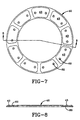
- reference numeral 44 designates generally a friction disk that is provided at spaced intervals on its outer periphery with a plurality of notches 40. Notches 40 receive the drive keys of a rotatable wheel assembly so that the rotor disks 44 are rotated with the wheel while being capable of axial movement relative to the wheel.
- Friction rotor disk 44 includes an annular carrier 45 and friction linings 42 secured thereto by mechanical fasteners such as rivets 48.
- the carrier 45 of friction rotor disk 44 is preferably formed of a material chosen for its structural properties, such as type 1722 steel available from The Timken Company, other metal or carbon composite. As shown in Figures 4 and 5, the carrier 45 of a rotor disk 44 includes a circumferentially extending strap 46 provided at circumferentally spaced intervals with radially extending legs 47.
- the carrrier 45 includes a pair of concentric circumferentially extending straps 46, one defining its outer periphery, the other defining its inner periphery, with a plurality of legs 47 extending radially therebetween and joining the inner and outer straps, thereby defining a plurality of recessed regions in the form of windows 50 devoid of any material.
- the junctions 66 of the radially extending legs 47 with the circumferentially extending straps 46 preferably are generously radiused to minimize thermally induced stresses; this also provides bearing area for transfer of forces between the friction lining 42 and the carrier 45.
- the carrier is preferably formed as a single unitary member, e.g.
- the carrier may be formed of segments that are mechanically joined together, e.g. in the manner shown in any of U.S. Patent Nos. 3,731,769 to Ely, 3,550,740 to LeBlanc et al. and 4,747,473 to Bok et al.
- Carriers for all rotor disks and stator disks may be cut or machined from flat plate of the chosen material. Casting is efficient for production of carriers having a complex shape including areas of reduced thickness.
- recessed regions 34 are preferably formed without cutting completely through the thickness of the carrier.
- additional recesses 57 may be formed in the face directed away from the piston motors 25 for engagement with the torque transfer buttons 58 secured to the flared reaction end 33 of the torque tube 32.
- the friction lining 42 may be formed of any suitable material chosen primarily for its frictional, wear resistance and heat capacity properties, and secondarily for its structural, corrosion and oxidation resistance properties.
- the friction lining 42 is preferably formed of material selected primarily for its tribological properties.
- the friction lining may be advangeously formed of carbon, graphite, ceramic or sintered metallic material.
- the friction lining is preferably in the form of an annular ring of a size corresponding to the carrier, but may be in the form of individual pads or sectors of an annular ring. Pads or sectors of currently available carbon material have been found to wear much faster than continuous annular friction members of the same material.
- each friction lining 42 has a flat annular wear face or rubbing face 60 adapted for engagment with the opposing wear face 60 of an adjacent friction lining 42.
- the obverse face of each friction lining 42 having a plurality of raised areas 43 corresponding in shape to the recessed regions 34 or window regions 50 of the carrier 37, 41, 45 with which the lining is designed to be used.
- the mating engagement of the periphery of the raised areas 43 with the recessed regions 34 or window regions 50 provides a large bearing surface for transfer of the forces generated during braking action, thereby preventing rotation of the friction lining 42 relative to the carrier 37, 41, 45, and locates the position of the friction lining 42 relative to the carrier 37, 41, 45.
- the friction lining when the friction lining is formed of a non-structural material such as sintered metallic material, the friction lining may be provided on its obverse face with a structural casing 70, e.g. of steel, which is configured to matingly engage with the recessed regions 34 or window regions 50 of the associated carrier.
- the friction linings 42 of the pressure plate 38, end plate 36, stator disks 39 and rotor disks 44 may be and preferably are identical.
- the thickness of the raised areas 43 of each friction lining 42 is slightly more than one half of the thickness of the carrier 37, 41, 45.
- Each friction lining 42 includes a plurality of apertures 62 extending therethrough in the thickness direction of the raised areas 43.
- Recessed rivets 48 preferably of type 304 stainless steel, secure the friction linings 42 to each other.
- all rivets lie on a common circle when the friction linings are formed of carbon to minimze the formation of wear tracks on wear faces 60.
- the rivets 48 are not tensioned against the friction lining 42 when installed at ambient temperature and the length of the rivets 48 is at least equal to the thickness of the associated carrier, thereby ensuring that upon thermal cycling from ambient temperature the rivets will not be tensioned and cause cracking or distortion of the friction lining.
- pressure plate 38 is similar to that of rotor 44 and stator 39, except that the recessed regions 34 of carrier 37 are not cut all the way through the thickness of the carrier, and the carrier is provided with drive notches 40 around its inner periphery rather than its outer periphery.
- the friction lining 42 of the pressure plate 38 may be and preferably is identical to that of the rotor disks 44, and is secured to carrier 37 by rivets 48 passing through the raised areas 43 of the linings and recessed regions 34 of the carrier.
- the depth of the recessed regions 34 of carrier 37 is slightly less than the height of the raised areas 43 of the friction lining 42 to ensure that the raised areas of the friction lining bear on the bottom of the recessed regions.
- the carrier 37 of pressure plate 38 is formed of type 1722 steel of about 0.30 inch (7,6 mm) thickness and the lining is formed of carbon, a thickness clearance of from zero to about 0.003 inch (0,076 mm) is provided.
- the construction of the end plate 36 is dependent on the design of the reaction end of the torque tube 32. Where the design (not illustrated) of the torque tube provides a series of splines for engagement by corresponding notches formed on the inner periphery of the carrier of the end-plate, the end plate 36 may be of a construction similar or identical to that of the pressure plate 38.
- the carrier 64 of the end plate 36 may be provided with a plurality of torque transfer recesses 57 for engagment with the plurality of torque transfer buttons 58.
- the friction lining 42 is secured to its carrier by a plurality of rivets 48 which pass through the regions of greatest thickness of the friction lining and recessed regions of the carrier.
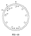
- FIG 13 there is shown another embodiment of a carrier for a friction disk (rotor) according to the invention.
- the radial legs 47 extend radially inwardly less than the full radial extent of the associated friction lining (not illustrated).
- a carrier for a friction disk (rotor) shown in Figure 14 most of the outer circumferentially extending strap is removed between adjacent radial legs 47.
- Similar alternate embodiments of carriers for stator disks are also possible and within the invention.
- radial legs 47 are reduced in cross section between radially inner and radially outer straps 46 to form an I-beam, which is believed to reduce the thermally induced stresses in carrier 45 that would otherwise occur in service.
- the friction linings 42 When the friction linings 42 have become sufficiently worn that they must be replaced, it is merely necessary to remove the rivets 48, discard the worn friction linings, position new friction linings on either side of the carrier and rivet the new friction linings into place. With exception of the pressure plate 38 and end plate 36, rivets preferably do not pass through apertures in the carrier. Thus, there is little risk of damage to the Carriers 45 of the rotor disks 44 and carriers 41 of the stator disks 39 during refurbishment. Where the friction lining is provided with structural casing, apertures for mounting the lining may be formed in the casing outside of the rubbing or contacting area of the wear faces, e.g. radially outwardly or radially inwardly of the wear faces.
- the thickness of the carriers at their drive notches 40 is comparable to those of conventional steel brakes to assure long life and the ability to be relined several times. As shown in Figures 15 and 16, the thickness of the radial legs 47 may be reduced relative to the thickness of the circumferential straps 46. This, too, is believed to reduce the thermally induced stresses in the carrier that would otherwise occur in service.
- a friction lining 42 formed of segments 67 of sintered metallic material 69 that is provided on its obverse face with a structural casing 70, e.g. of steel, that is configured to matingly engage with the recessed regions 34 or window regions 50 of the associated carrier and to provide cups which support the sintered metallic material.
- structural casing 70 permits location of the fasteners such as rivets 48 in the structural casing outside of the rubbing or contacting area of the wear faces, e.g. radially outwardly or radially inwardly of the wear faces, or in recessed regions between the circumferentially spaced segments 67 of sintered metallic material.
- the thickness of a steel carrier for a carbon lined brake assembly suitable for use on a Boeing 737 aircraft is about 0.30 inches (7,6 mm)
- the thickness of the friction linings for this same application when formed of carbon is about 0.44 inches (11,2 mm) in the raised areas, and about 0.29 inches (7,4 mm) elsewhere.
- the carrier may be formed of any suitable material chosen primarily for its structural properties, and secondarily for its heat capacity.
- the carrier may advantageously formed of metal such as steel, beryllium, titanium or Inconel, or of carbon and/or ceramic composite material designed for structural strength and resistance to corrosion and oxidation.
- Beryllium carriers may be provided with drive notch reinforcement of a different material such as steel to eliminate beryllium dust.
- the carriers are formed of structural material such as type 1722 steel or the like, there is no need to utilize costly drive clips.
- the carrier is formed of steel, it is preferable that the obverse side of any carbon friction lining be treated against oxidative attack due to proximity or contact with the steel carrier; alternatively, the steel carrier may be plated to inhibit such oxidative attack.
- the carrier(s) may be coated with a refractory thermal barrier material, e.g. ceramic material.
- a refractory thermal barrier material e.g. ceramic material.
- the middle portions 49 of radial legs 47 of carrier 45 are provided with thermal barrier coating 68, to retard separation of radially outer circumferential strap 46 from the remainder of the carrier and its associated friction lining(s) during such a high energy input condition.
Landscapes
- Engineering & Computer Science (AREA)
- General Engineering & Computer Science (AREA)
- Mechanical Engineering (AREA)
- Braking Arrangements (AREA)
Claims (15)
- Reibscheibe mit einem ringförmigen Träger (45), der mehrere entlang seiner Umfangsrichtung mit Abständen angeordnete vertiefte Bereiche (34) und Drehkraft-Antriebskerben (40), und ein Paar einstückiger Reibbeläge (42) aufweist, die an gegenüberliegenden Seiten des Trägers angeordnet sind, wobei jeder der Reibbeläge (42) eine mit dem ringförmigen Träger koaxiale flache ringförmige Verschleißfläche und eine entgegengesetzte Fläche mit erhabenen Bereichen (43) aufweist, die den Wänden der vertieften Bereiche (34,50) des Trägers entsprechen und passend mit ihnen zusammengreifen, um eine Drehkraftübertragungsfunktion zwischen dem Belag (42) und dem Träger zu schaffen,
dadurch gekennzeichnet, dassdie erhabenen Bereiche (43) eines der Reibbeläge eines Paars an die erhabenen Bereiche des anderen Reibbelags drücken, unddass die Tiefe der vertieften Bereiche (34,50) etwas kleiner ist als die Höhe der erhabenen Bereiche (43). - Scheibe nach Anspruch 1, bei der der Träger (45) einen umfangsmäßig verlaufenden Streifen (46) mit mehreren Schenkeln (47) aufweist, die radial von dem Streifen abstehen und mit den erhabenen Bereichen (43) des Reibbelags (42) zusammengreifen.
- Scheibe nach Anspruch 1, bei der mindestens ein Teil des Trägers eine Wärmebarriere-Beschichtung (68) aufweist.
- Scheibe nach Anspruch 2, bei der der Streifen (46) durchgehend ist und den radialen Außenumfang des Trägers begrenzt, und die Schenkel (47) radial einwärts von dem Streifen abstehen, wobei der Streifen mit Abständen um seinen Außenumfang angeordnete Drehkraft-Antriebskerben (40) aufweist.
- Scheibe nach Anspruch 2, bei der der Streifen (42) den radialen Innenumfang des Trägers (45) begrenzt und die Schenkel (47) radial auswärts von dem Streifen abstehen, wobei der Streifen mit Abständen um seinen radialen Innenumfang angeordnete Drehkraft-Antriebskerben (40) aufweist.
- Scheibe nach Anspruch 2, bei der die radiale Erstreckung der Schenkel (47) kleiner ist als diejenige der Verschleißfläche des Reibbelags (42).
- Scheibe nach Anspruch 2, bei der die radial verlaufenden Schenkel (47) eine I-förmige Querschnittskonfiguration haben.
- Scheibe nach Anspruch 1, bei der der Träger (45) in Form konzentrischer radial innerer und radial äußerer umfangsmäßig verlaufender Streifen (46) ausgebildet ist, mit denen mehrere radial zwischen diesen verlaufende Schenkel (47) verbunden sind, die vertieften Bereiche (34,50) begrenzen.
- Scheibe nach Anspruch 1, bei der der Reibbelag (42) Öffnungen (50) aufweist, die mit mechanischen Befestigungsvorrichtungen (62) versehen sind, welche den Reibbelag ohne Spannung gegen den Reibbelag an dem Träger festhalten.
- Scheibe nach Anspruch 1, bei der der Träger (45) Metall aufweist und der Reibbelag (42) ein durchgehendes Ringteil ist, das Kohlenstoff, Graphit, Keramik oder gesintertes metallisches Material aufweist.
- Verfahren zum Aufarbeiten einer verschlissenen Reibscheibe (36,38,39, 44) mit einem ringförmigen Träger (37,41,45), der mehrere entlang seiner Umfangsrichtung mit Abständen angeordnete vertiefte Bereiche (34,50) und Drehkraft-Antriebskerben (40) und ein Paar einstückiger Reibbeläge (42) aufweist, die an gegenüberliegenden Seiten des Trägers angeordnet sind, wobei jeder der Reibbeläge eine mit dem ringförmigen Träger koaxiale, flache ringförmige Verschleißfläche und eine entgegengesetzte Fläche mit erhabenen Bereichen (43) aufweist, die den Wänden der vertieften Bereiche (34,50) des Trägers entsprechen und passend mit ihnen zusammengreifen, um eine Drehkraftübertragungsfunktion zwischen dem Belag und dem Träger zu schaffen, wobei in dem Verfahren zwecks Erzeugens einer gewünschten Vorrichtungsdicke der verschlissene Reibbelag durch einen neuen Reibbelag (42) ersetzt wird, der eine flache Verschleißfläche und eine entgegengesetzte Fläche mit erhabenen Bereichen (43) aufweist, die den vertieften Bereichen (34,50) des Trägers (37,41,45) entsprechen und passend mit ihnen zusammengreifen, um eine Drehkraftübertragungsfunktion zwischen dem Belag und dem Träger zu schaffen,
dadurch gekennzeichnet, dassdie erhabenen Bereiche (43) eines der Reibbeläge an die erhabenen Bereiche des anderen Reibbelags drücken, unddass die erhabenen Bereiche (43) des Reibbelags (42) mit einer Höhe ausgebildet sind, die etwas größer ist als die Tiefe der vertieften Bereiche (34,50). - Verfahren nach Anspruch 11, bei dem ferner der neue Reibbelag durch Nieten gesichert wird, ohne die Nieten zu spannen.
- Verfahren nach Anspruch 12, bei dem ferner ein Paar neuer Reibbeläge an gegenüberliegenden Seiten des Trägers gesichert wird, und zwar unter Kontakt der erhabenen Bereiche (43) eines der Reibbeläge mit den erhabenen Bereichen des anderen der Reibbeläge, wobei bei Befestigung an dem Träger (45) die erhabenen Bereiche (43) des Paars von Reibbelägen die Reibbeläge (42) gegen eine während des Bremsvorgangs einwirkende Klemmlast drücken.
- Verfahren nach Anspruch 11, bei dem der Träger einen umfangsmäßig verlaufenden Streifen (46) mit mehreren Schenkeln (47) aufweist, die radial von dem Streifen abstehen, um die vertieften Bereiche (34,50) des Trägers zu begrenzen, und die mit den erhabenen Bereichen (43) des Reibbelags (42) zusammengreifen, wobei in dem Verfahren ferner ein neuer Reibbelag, der gesintertes Metall-Material aufweist, an seiner gegenüberliegenden Seite mit einem strukturellen Gehäuse (70) versehen wird, das zum passenden Zusammengreifen mit den Wänden der vertieften Bereiche des Trägers (45) konfiguriert ist.
- Verfahren nach Anspruch 13, bei dem der Träger (45) Metall aufweist und der Reibbelag (42) Kohlenstoff aufweist und die Dicke der vorstehenden Bereiche (43) jedes Reibbelags etwas größer ist als die halbe Dicke des Trägers (45).
Applications Claiming Priority (2)
| Application Number | Priority Date | Filing Date | Title |
|---|---|---|---|
| US08/449,437 US5558186A (en) | 1995-05-24 | 1995-05-24 | Friction disk with renewable wear faces |
| US449437 | 1999-11-24 |
Publications (2)
| Publication Number | Publication Date |
|---|---|
| EP0744560A1 EP0744560A1 (de) | 1996-11-27 |
| EP0744560B1 true EP0744560B1 (de) | 2001-10-31 |
Family
ID=23784162
Family Applications (1)
| Application Number | Title | Priority Date | Filing Date |
|---|---|---|---|
| EP96107050A Expired - Lifetime EP0744560B1 (de) | 1995-05-24 | 1996-05-04 | Reibscheibe mit erneuerbaren Verschleissflächen |
Country Status (4)
| Country | Link |
|---|---|
| US (1) | US5558186A (de) |
| EP (1) | EP0744560B1 (de) |
| JP (1) | JPH09242798A (de) |
| DE (1) | DE69616422T2 (de) |
Families Citing this family (43)
| Publication number | Priority date | Publication date | Assignee | Title |
|---|---|---|---|---|
| US5779006A (en) * | 1995-05-24 | 1998-07-14 | The B. F. Goodrich Company | Composite friction disk having replaceable wear faces |
| AT402961B (de) * | 1996-03-25 | 1997-10-27 | Hoerbiger & Co | Reibsystem |
| US5709288A (en) * | 1996-09-19 | 1998-01-20 | The B.F. Goodrich Company | Clamshell cup friction article and method |
| FR2755094B1 (fr) * | 1996-10-31 | 1998-11-27 | Messier Bugatti | Agencement de disques de frein en carbone pour unite de freinage d'aeronef, et procede d'assemblage de disques selon un tel agencement |
| DE19740597B4 (de) * | 1997-09-15 | 2008-03-27 | Goldbach Automobile Consulting Gmbh | Scheibenbremse |
| GB9817763D0 (en) * | 1998-08-15 | 1998-10-14 | T & N Technology Ltd | Friction material supporting assembly for a disc brake |
| GB2340566B (en) * | 1998-08-15 | 2002-11-06 | T & N Technology Ltd | Disc brake pad assembly |
| US7090057B2 (en) | 2001-06-04 | 2006-08-15 | Honeywell International Inc. | Composite friction disc with structural core and refurbishable lining elements |
| US6902044B2 (en) * | 2002-10-15 | 2005-06-07 | Arvinmeritor Technology, Llc | Disc pad assembly without backing plate |
| DE10257353A1 (de) * | 2002-12-05 | 2004-06-17 | Goldbach Automobile Consulting Gmbh | Scheibenbremse mit Belagträger |
| WO2004051110A1 (de) * | 2002-12-05 | 2004-06-17 | Goldbach Automobile Consulting Gmbh | Scheibenbremse mit belagträger |
| US6935470B1 (en) | 2002-12-31 | 2005-08-30 | Robert P. Smith, Jr. | Disk brake |
| BRPI0412645B1 (pt) | 2003-07-15 | 2018-02-14 | Dunlop Aerospace Limited | Artigo compósito e método de formação do mesmo |
| GB2403989B (en) * | 2003-07-15 | 2006-06-14 | Dunlop Aerospace Ltd | Composite article |
| FR2859259B1 (fr) | 2003-08-28 | 2006-02-03 | Messier Bugatti | Ensemble de freinage d'aeronef |
| US7216744B2 (en) * | 2004-06-03 | 2007-05-15 | Sepac, Inc. | Arc brake |
| US7441788B2 (en) * | 2004-07-09 | 2008-10-28 | Bombardier Recreational Products Inc. | Front drive geometry for an all-terrain vehicle |
| EP1814929B1 (de) * | 2004-11-09 | 2008-09-17 | E.I. Du Pont De Nemours And Company | Polymerisation von makrocyclischen polyesteroligomeren bei erhöhter temperatur mit seltenerdelement-katalysatoren |
| DE102005031291A1 (de) * | 2005-07-05 | 2007-01-11 | Daimlerchrysler Ag | Verbundbremsscheibe |
| US7543691B2 (en) * | 2006-07-12 | 2009-06-09 | Delphi Technologies, Inc. | Brake rotor assembly |
| US7500546B2 (en) * | 2006-09-11 | 2009-03-10 | Goodrich Corporation | Brake lining cup attachment method for reduced wear |
| US20080131621A1 (en) * | 2006-12-05 | 2008-06-05 | Warran Boyd Lineton | Method for fusing hard ceramic-metallic layer on a brake rotor |
| US8281907B2 (en) * | 2007-12-03 | 2012-10-09 | Honeywell International Inc. | Brake assembly having multi-piece core and replaceable friction surfaces |
| US8408369B2 (en) * | 2009-09-08 | 2013-04-02 | GM Global Technology Operations LLC | Bimetallic brake rotor |
| CN103299100B (zh) * | 2010-12-13 | 2016-06-08 | 舍弗勒技术股份两合公司 | 用于制造摩擦体的方法 |
| WO2014145227A1 (en) | 2013-03-15 | 2014-09-18 | Tech M3, Inc. | Wear resistant braking systems |
| WO2014145231A2 (en) | 2013-03-15 | 2014-09-18 | Tech M3, Inc. | Braking systems incorporating wear and corrosion resistant rotors |
| US9315261B2 (en) | 2013-06-26 | 2016-04-19 | Goodrich Corporation | Keyed brake disk assembly |
| US9194447B2 (en) * | 2013-11-11 | 2015-11-24 | Goodrich Corporation | Keyed brake disk assembly |
| US10151355B2 (en) * | 2014-04-01 | 2018-12-11 | Borgwarner Inc. | Using phase change materials for temperature management in clutch assemblies, torque converter clutch assemblies, and brake assemblies |
| US20170184164A1 (en) * | 2014-05-19 | 2017-06-29 | Tech M3, Inc | Brake Rotor With Working Surface Inserts |
| US9909632B2 (en) * | 2015-12-28 | 2018-03-06 | Goodrich Corporation | Plate assemblies including floating wear linings for multi-disk brake systems and methods for reducing vibration in a multi-disk brake system |
| US10228030B2 (en) * | 2017-05-15 | 2019-03-12 | Goodrich Corporation | Multi-disk brake assembly with travel limit pin |
| US10274034B2 (en) * | 2017-07-12 | 2019-04-30 | Goodrich Corporation | Wear liner with integrated torque button |
| US10941823B2 (en) * | 2017-11-27 | 2021-03-09 | Goodrich Corporation | Segmented wear liner |
| FR3085453B1 (fr) * | 2018-08-29 | 2020-11-20 | Safran Landing Systems | Disque arriere d’une pile de disques en carbone de frein d’aeronef equipe de plots, et frein faisant application |
| US11125289B2 (en) * | 2019-07-03 | 2021-09-21 | Honeywell International Inc. | Brake disc assembly |
| CN114466981A (zh) * | 2019-10-14 | 2022-05-10 | 沃尔沃卡车集团 | 制动盘和车辆 |
| CN114514387B (zh) * | 2019-10-14 | 2024-07-09 | 沃尔沃卡车集团 | 制动盘和车辆 |
| US11384805B2 (en) | 2019-11-21 | 2022-07-12 | Honeywell International Inc. | Brake disc assembly |
| FR3113922B1 (fr) * | 2020-09-08 | 2023-03-31 | Safran Aircraft Engines | Frein de turbine |
| US20220097832A1 (en) * | 2020-09-29 | 2022-03-31 | Goodrich Corporation | Hybrid brake system |
| US11834159B2 (en) * | 2021-10-18 | 2023-12-05 | Goodrich Corporation | Torque button bushing |
Family Cites Families (18)
| Publication number | Priority date | Publication date | Assignee | Title |
|---|---|---|---|---|
| BE341487A (de) * | ||||
| FR1218486A (fr) * | 1958-12-09 | 1960-05-11 | Ferodo Sa | Dispositif de fixation d'une garniture de frottement sur un support |
| DE1425296A1 (de) * | 1962-04-06 | 1968-11-07 | Jurid Werke Gmbh | Traeger fuer Reibelemente-Paar |
| GB1242061A (en) * | 1967-09-12 | 1971-08-11 | Hickson S Timber Impregnation | Process and apparatus for impregnating timber |
| CH528684A (fr) * | 1970-02-12 | 1972-09-30 | Messier Sa | Frein à disques |
| US3708042A (en) * | 1970-09-21 | 1973-01-02 | Bendix Corp | Carbon core segmented friction disc |
| DE2363427A1 (de) * | 1973-12-20 | 1975-06-26 | Licentia Gmbh | Reibscheibe fuer kupplungen oder bremsen |
| US3913716A (en) * | 1974-04-04 | 1975-10-21 | Abex Corp | Welded friction article and method of assembly |
| GB1496341A (en) * | 1974-06-04 | 1977-12-30 | Girling Ltd | Spreading disc brakes |
| US3920108A (en) * | 1974-08-22 | 1975-11-18 | Goodrich Co B F | Friction disc member for brake or clutch |
| US4276969A (en) * | 1979-04-02 | 1981-07-07 | Goodyear Aerospace Corporation | Method and means for fastening friction wear pads |
| JPS58211031A (ja) * | 1982-06-03 | 1983-12-08 | Akebono Brake Ind Co Ltd | 2層式摩擦材の製造方法 |
| FR2549922B1 (fr) * | 1983-07-25 | 1985-11-15 | Valeo | Fixation d'une garniture sur un disque de friction, notamment pour embrayage de vehicule automobile |
| FR2553485B1 (fr) * | 1983-10-17 | 1989-05-05 | Goodrich Co B F | Disque de frein ou d'embrayage poreux reutilisable en composite carbone et procede de fabrication |
| FR2557240B1 (fr) * | 1983-12-21 | 1989-05-19 | Europ Propulsion | Disque de frein a garnitures demontables |
| GB2191830B (en) * | 1986-06-18 | 1990-02-28 | Automotive Products Plc | Friction material and cover plate assembly |
| JP2675136B2 (ja) * | 1989-04-27 | 1997-11-12 | 株式会社曙ブレーキ中央技術研究所 | ディスクブレーキ |
| FR2697218B1 (fr) * | 1992-10-26 | 1994-12-16 | Alsthom Gec | Système de freinage pour véhicule ferroviaire utilisant des matériaux à base de carbone. |
-
1995
- 1995-05-24 US US08/449,437 patent/US5558186A/en not_active Expired - Lifetime
-
1996
- 1996-05-04 DE DE69616422T patent/DE69616422T2/de not_active Expired - Fee Related
- 1996-05-04 EP EP96107050A patent/EP0744560B1/de not_active Expired - Lifetime
- 1996-05-17 JP JP8123721A patent/JPH09242798A/ja not_active Withdrawn
Also Published As
| Publication number | Publication date |
|---|---|
| US5558186A (en) | 1996-09-24 |
| JPH09242798A (ja) | 1997-09-16 |
| EP0744560A1 (de) | 1996-11-27 |
| DE69616422D1 (de) | 2001-12-06 |
| DE69616422T2 (de) | 2002-06-20 |
Similar Documents
| Publication | Publication Date | Title |
|---|---|---|
| EP0744560B1 (de) | Reibscheibe mit erneuerbaren Verschleissflächen | |
| EP0833071B1 (de) | Komposit- Reibscheibe mit austauschbaren Verschleissflächen | |
| US9541145B2 (en) | Keyed brake disk assembly | |
| US3605967A (en) | Protective bearing member for brake or clutch | |
| EP2878846B1 (de) | Verkeilte Bremsscheibenanordnung | |
| US7090057B2 (en) | Composite friction disc with structural core and refurbishable lining elements | |
| US5709288A (en) | Clamshell cup friction article and method | |
| EP1103738B1 (de) | In drei Etappen auswechselbarer Bremsscheibensatz sowie Verfahren für den Zusammenbau | |
| EP0716244B1 (de) | Flugzeugbremse | |
| EP2165087B1 (de) | Drehmomentplatten-rückausleger mit asymmetrischer bremse | |
| EP3489538B1 (de) | Segmentierter verschleissschutz | |
| US5503254A (en) | Toughened carbon composite brake discs | |
| GB2234024A (en) | Laminated friction disc | |
| US5199536A (en) | Heatshield installation for aircraft brake | |
| EP2749785B1 (de) | Bremsscheibenanordnung | |
| US20170138423A1 (en) | Damper brake | |
| US4742895A (en) | Disk brake assembly | |
| US3759354A (en) | Brake disc structure | |
| US5769185A (en) | Carbon brake disc structures and method of making same | |
| US9482299B1 (en) | Multi-leaved core brake disks and assemblies | |
| EP1052422B1 (de) | In drei Etappen auswechselbarer Bremsscheibensatz sowie Verfahren für den Zusammenbau | |
| EP3051166B1 (de) | Reibscheiben mit schwimmenden verschleissauskleidungen | |
| EP0020389B1 (de) | Scheibenbremse mit geteilten scheiben | |
| GB2161560A (en) | Wheel and brake assembly | |
| EP3712457B1 (de) | Segmentierte nietlose verschleissauskleidung mit strukturellem kohlenstoff- oder keramikkern |
Legal Events
| Date | Code | Title | Description |
|---|---|---|---|
| PUAI | Public reference made under article 153(3) epc to a published international application that has entered the european phase |
Free format text: ORIGINAL CODE: 0009012 |
|
| AK | Designated contracting states |
Kind code of ref document: A1 Designated state(s): DE FR GB |
|
| 17P | Request for examination filed |
Effective date: 19970502 |
|
| 17Q | First examination report despatched |
Effective date: 19990216 |
|
| GRAG | Despatch of communication of intention to grant |
Free format text: ORIGINAL CODE: EPIDOS AGRA |
|
| GRAG | Despatch of communication of intention to grant |
Free format text: ORIGINAL CODE: EPIDOS AGRA |
|
| GRAH | Despatch of communication of intention to grant a patent |
Free format text: ORIGINAL CODE: EPIDOS IGRA |
|
| GRAH | Despatch of communication of intention to grant a patent |
Free format text: ORIGINAL CODE: EPIDOS IGRA |
|
| GRAA | (expected) grant |
Free format text: ORIGINAL CODE: 0009210 |
|
| AK | Designated contracting states |
Kind code of ref document: B1 Designated state(s): DE FR GB |
|
| REF | Corresponds to: |
Ref document number: 69616422 Country of ref document: DE Date of ref document: 20011206 |
|
| REG | Reference to a national code |
Ref country code: GB Ref legal event code: IF02 |
|
| ET | Fr: translation filed | ||
| RAP2 | Party data changed (patent owner data changed or rights of a patent transferred) |
Owner name: GOODRICH CORPORATION |
|
| PLBE | No opposition filed within time limit |
Free format text: ORIGINAL CODE: 0009261 |
|
| STAA | Information on the status of an ep patent application or granted ep patent |
Free format text: STATUS: NO OPPOSITION FILED WITHIN TIME LIMIT |
|
| 26N | No opposition filed | ||
| PGFP | Annual fee paid to national office [announced via postgrant information from national office to epo] |
Ref country code: DE Payment date: 20030626 Year of fee payment: 8 |
|
| PG25 | Lapsed in a contracting state [announced via postgrant information from national office to epo] |
Ref country code: DE Free format text: LAPSE BECAUSE OF NON-PAYMENT OF DUE FEES Effective date: 20041201 |
|
| PGFP | Annual fee paid to national office [announced via postgrant information from national office to epo] |
Ref country code: FR Payment date: 20110607 Year of fee payment: 16 |
|
| PGFP | Annual fee paid to national office [announced via postgrant information from national office to epo] |
Ref country code: GB Payment date: 20110525 Year of fee payment: 16 |
|
| GBPC | Gb: european patent ceased through non-payment of renewal fee |
Effective date: 20120504 |
|
| REG | Reference to a national code |
Ref country code: FR Ref legal event code: ST Effective date: 20130131 |
|
| PG25 | Lapsed in a contracting state [announced via postgrant information from national office to epo] |
Ref country code: GB Free format text: LAPSE BECAUSE OF NON-PAYMENT OF DUE FEES Effective date: 20120504 Ref country code: FR Free format text: LAPSE BECAUSE OF NON-PAYMENT OF DUE FEES Effective date: 20120531 |