EP0743661A2 - Compensation device - Google Patents
Compensation device Download PDFInfo
- Publication number
- EP0743661A2 EP0743661A2 EP96105262A EP96105262A EP0743661A2 EP 0743661 A2 EP0743661 A2 EP 0743661A2 EP 96105262 A EP96105262 A EP 96105262A EP 96105262 A EP96105262 A EP 96105262A EP 0743661 A2 EP0743661 A2 EP 0743661A2
- Authority
- EP
- European Patent Office
- Prior art keywords
- compensating
- expansion tank
- plate
- compensation
- bellows
- Prior art date
- Legal status (The legal status is an assumption and is not a legal conclusion. Google has not performed a legal analysis and makes no representation as to the accuracy of the status listed.)
- Granted
Links
Images
Classifications
-
- H—ELECTRICITY
- H01—ELECTRIC ELEMENTS
- H01F—MAGNETS; INDUCTANCES; TRANSFORMERS; SELECTION OF MATERIALS FOR THEIR MAGNETIC PROPERTIES
- H01F27/00—Details of transformers or inductances, in general
- H01F27/08—Cooling; Ventilating
- H01F27/10—Liquid cooling
- H01F27/12—Oil cooling
- H01F27/14—Expansion chambers; Oil conservators; Gas cushions; Arrangements for purifying, drying, or filling
-
- B—PERFORMING OPERATIONS; TRANSPORTING
- B61—RAILWAYS
- B61C—LOCOMOTIVES; MOTOR RAILCARS
- B61C3/00—Electric locomotives or railcars
Abstract
Description
Die Erfindung betrifft eine Ausgleichsvorrichtung, insbesondere für den Einsatz bei Transformatoren von Schienenfahrzeugen, mit einem Ausgleichsbehälter, der eine fluidführende Verbindung mit dem Inneren des Gehäuses des Transformators aufweist, wobei in dem Ausgleichsbehälter eine längs einer Verstellachse verfahrbare Ausgleichsplatte angeordnet ist, die unter der Einwirkung eines Kraftspeichers in Anlage mit dem im Ausgleichsbehälter aufgenommenen Trafoöl ist.The invention relates to a compensating device, in particular for use in transformers of rail vehicles, with a compensating tank which has a fluid-carrying connection to the interior of the housing of the transformer, a compensating plate which can be moved along an adjustment axis and which is arranged under the action of a The energy accumulator is in contact with the transformer oil contained in the expansion tank.
Bei dem Betrieb von Transformatoren (Trafos) bei Schienenfahrzeugen treten Arbeitstemperaturen von -30° bis 135°C auf und das im Trafo verwendete Trafoöl, meist in Form von Silikonöl, unterliegt Volumenschwankungen von mehr als 10 %. Um diese temperaturbedingten Volumenschwankungen ausgleichen zu können, ist es Stand der Technik, oberhalb des Transformators oder Trafos einen Ausgleichsbehälter anzuordnen, der Trafoöl bevorratet und über eine fluidführende Verbindung in das Innere des Gehäuses des Trafos abgibt, sofern niedrige Betriebstemperaturen vorliegen, aber auch im Betrieb bei hohen Temperaturen in der Art eines Ausgleichsgefäßes vom Trafo stammendes Trafoöl aufnimmt. Insbesondere beim Einsatz dahingehender Ausgleichsbehälter in Schienenfahrzeugen kommt es zu Problemen. Zum einen können beim Betrieb des Schienenfahrzeuges Querbeschleunigungen in der Größe von 5 g auftreten, die ein homogenes Zu- oder Abfließen des Trafoöles über die fluidführende Verbindung verhindern, und im übrigen ist ein Hin- und Herschwappen des Trafoöles innerhalb des Ausgleichsbehälters aus naheliegenden Gründen bereits unerwünscht.When transformers (transformers) are operated on rail vehicles, working temperatures of -30 ° to 135 ° C occur and the transformer oil used in the transformer, usually in the form of silicone oil, is subject to volume fluctuations of more than 10%. In order to be able to compensate for these temperature-related volume fluctuations, it is state of the art to arrange an expansion tank above the transformer or transformer, which stores transformer oil and releases it via a fluid-carrying connection into the interior of the transformer housing, provided that the operating temperatures are low, but also during operation absorbs high temperatures in the manner of a compensating vessel from the transformer oil. Problems arise in particular when using this type of expansion tank in rail vehicles. On the one hand, lateral accelerations can occur during the operation of the rail vehicle occur in the size of 5 g, which prevent a homogeneous inflow or outflow of the transformer oil via the fluid-carrying connection, and for the rest a back and forth sloshing of the transformer oil within the expansion tank is already undesirable for obvious reasons.
Aus Kostengründen wird bei der notwendigen Wartung des Trafos dieser vollständig aus dem Schienenfahrzeug entfernt und gegen einen neuen oder bereits gewarteten Trafo ausgetauscht. Auf diese Art und Weise werden unnötige Stillstandszeiten des Schienenfahrzeuges vermieden. Bei einem dahingehenden Ein- und Ausbau ist aber die darüber angeordnete konventionelle Ausgleichsvorrichtung im Weg und behindert einen raschen Ein- und Ausbau des Trafos. Auch wäre es bereits aus Platzgründen heraus zweckmäßig, die Ausgleichsvorrichtung im Unterflurbereich des Schienenfahrzeuges anzuordnen.For cost reasons, the necessary maintenance of the transformer is completely removed from the rail vehicle and replaced with a new or already maintained transformer. In this way, unnecessary downtimes of the rail vehicle are avoided. In the event of this being installed and removed, the conventional compensating device arranged above is in the way and hinders rapid installation and removal of the transformer. It would also be expedient, for reasons of space, to arrange the compensation device in the underfloor area of the rail vehicle.
Durch die DD-WP 62 619 ist eine gattungsgemäße Ausgleichsvorrichtung bekannt, die ohne Führungseinrichtung für ihre Ausgleichsplatte auskommt und mithin die beim Betrieb eines Schienenfahrzeuges angesprochenen hohen Querbeschleunigungen nicht funktionssicher aufnehmen kann. Zwar wirkt die Ausgleichsplatte bei der bekannten Ausgleichsvorrichtung mit auf ihrer Unterseite angebrachten Anschlägen zusammen, um eine Überdehnung des balgartigen Ausgleichsbehälters zu vermeiden; allein die dahingehende Anordnung baut konstruktiv groß auf und ist mithin nicht geeignet, im beengten Unterflurbereich eines Schienenfahrzeuges angeordnet zu werden. Auch ist die bekannte Ausgleichsvorrichtung als Anbauvorrichtung Teil des jeweiligen Transformators und mit diesem ein- und auszubauen, was entsprechend aufwendig ist und die Stillstandszeiten des Schienenfahrzeuges erhöht.DD-WP 62 619 discloses a compensation device of the generic type which does not require a guide device for its compensation plate and therefore cannot absorb the high lateral accelerations mentioned when operating a rail vehicle. The compensating plate in the known compensating device interacts with stops attached to its underside in order to avoid overexpansion of the bellows-like compensating container; the relevant arrangement alone is structurally large and is therefore not suitable for being arranged in the cramped underfloor area of a rail vehicle. The known compensating device as an attachment device is part of the respective transformer and is to be installed and removed with it, which is correspondingly complex and increases the downtimes of the rail vehicle.
Durch die DD-WP 62 621 ist eine Führungseinrichtung für eine Ausgleichsvorrichtung bei Transformatoren bekannt in Form eines Scherentriebes. Als Ausgleichsbehälter dienen dabei mindestens drei runde balgartige Körper, die derart angeordnet sind, daß ihre Längsachsen mit den Ecken eines Polygons zusammenfallen, wobei die endseitig angeordneten, als Deckel dienenden Ausgleichsplatten der balgartigen Körper über den Scherentrieb geführt sind. Der als Führungseinrichtung dienende Scherentrieb weist darüber hinaus Anschläge auf, die den Verfahrweg des Ausgleichsbehälters begrenzen und vor Überlastung schützen. Die dahingehend bekannte Ausgleichsvorrichtung baut ebenfalls groß auf und wäre für eine Anordnung im Unterflurbereich eines Schienenfahrzeuges nicht geeignet. Ferner sind Hemmungen des Scherentriebes nicht auszuschließen, sofern hohe Querbeschleunigungen auf die Ausgleichsvorrichtung einwirken.DD-WP 62 621 discloses a guide device for an equalizing device in transformers in the form of a scissor drive. At least three round bellows-like bodies, which are arranged in this way, serve as expansion tanks are that their longitudinal axes coincide with the corners of a polygon, with the compensating plates of the bellows-shaped bodies arranged at the ends and serving as lids being guided over the scissors drive. The scissor drive serving as a guide device also has stops which limit the travel of the expansion tank and protect against overloading. The known compensating device is also of a large size and would not be suitable for an arrangement in the underfloor area of a rail vehicle. Furthermore, inhibitions of the scissor drive cannot be ruled out, provided high transverse accelerations act on the compensating device.
Ausgehend von diesem Stand der Technik liegt der Erfindung die Aufgabe zugrunde, eine Ausgleichsvorrichtung zu schaffen, die in einem Schienenfahrzeug im Unterflurbereich anordenbar ist und die auch bei hohen Querbeschleunigungen eine kontinuierlich wirkende Fluidverbindung zwischen dem Ausgleichsbehälter und dem Trafogehäuse herstellt.
Eine dahingehende Aufgabe löst eine Vorrichtung mit den Merkmalen des Anspruches 1.Based on this prior art, the invention has for its object to provide a compensation device that can be arranged in a rail vehicle in the underfloor area and that creates a continuously acting fluid connection between the expansion tank and the transformer housing even at high lateral accelerations.
A corresponding object is achieved by a device having the features of claim 1.
Dadurch, daß erfindungsgemäß für das Verfahren der Ausgleichsplatte eine Führungseinrichtung vorgesehen ist, die zwei gegeneinander verschiebbare Hülsen aufweist, von denen eine mit der Ausgleichsplatte und die andere mit den feststehenden Teilen des Ausgleichsbehälters verbunden ist, und daß zumindest eine der Hülsen mit einer Anschlagfläche an der Ausgleichsplatte oder an dem Ausgleichsbehälter zusammenwirkt, ist das im Ausgleichsbehälter aufgenommene Trafoöl unter ständiger "Spannung" im Ausgleichsbehälter gehalten, so daß unter dem Druck der Ausgleichsplatte ein ständiges Nachfließen des Trafoöls in das Gehäuseinnere des Trafos gewährleistet ist. Bei einem Zuviel an Trafoöl im Trafogehäuse, beispielsweise bei hohen Betriebstemperaturen, wird dann entgegen der Wirkung des Kraftspeichers die Ausgleichsplatte um das abgegebene Übermaß an Volumen entsprechend angehoben, wobei auch in dieser Betriebssituation die Ausgleichsplatte eine ständige Druckkraft auf das bevorratete Trafoöl im Ausgleichsbehälter ausübt. Bei einer dahingehenden Anordnung, die der Niederdrucktechnologie zuzuordnen ist, kommt es auch nicht mehr zu dem ungewollten Schwappen des Trafoöls im Ausgleichsbehälter und auch bei hohen g-Beschleunigungen ist eine Funktion der Ausgleichsvorrichtung nicht in Frage gestellt.Characterized in that according to the invention a guide device is provided for the movement of the compensation plate, which has two mutually displaceable sleeves, one of which is connected to the compensation plate and the other to the fixed parts of the expansion tank, and that at least one of the sleeves with a stop surface on the Compensating plate or on the expansion tank interacts, the transformer oil received in the expansion tank is kept under constant "tension" in the expansion tank, so that a constant flow of the transformer oil into the interior of the transformer is guaranteed under the pressure of the expansion plate. If there is too much transformer oil in the transformer housing, for example at high operating temperatures, the compensating plate is then raised by the excess volume given off, contrary to the effect of the energy accumulator, the compensating plate also in this operating situation exerts constant pressure on the stored transformer oil in the expansion tank. With such an arrangement, which can be assigned to low-pressure technology, there is no longer any unwanted sloshing of the transformer oil in the expansion tank and even at high g-accelerations, a function of the compensation device is not in question.
Durch das lneinandergreifen der Hülsen und der besonderen Anordnung der jeweils vorgesehenen Anschlagfläche ist einer Überbeanspruchung des Faltenbalges durch zu starkes Zusammendrücken bedingt durch das Einströmen des Trafoöls in den Ausgleichsbehälter entgegengewirkt und eine sicher funktionierende Führungseinrichtung bei kleiner Einbaugröße verwirklicht, was den beengten Platzverhältnissen im Unterflurbereich eines Schienenfahrzeuges entgegenkommt. Ferner ist auch bei hohen Querbeschleunigungen durch die gegenseitige Abstützung der Hülsen der Führungseinrichtung ein störungsfreier Betrieb gewährleistet. Vorzugsweise sind hierbei die beiden Hülsen mit einem vorgebbaren Spiel gegeneinander verschiebbar, so daß Hemmungen der Ausgleichsvorrichtung mit Sicherheit vermieden sind.Due to the interlocking of the sleeves and the special arrangement of the respectively provided stop surface, overstressing of the bellows due to excessive compression due to the inflow of the transformer oil into the expansion tank is counteracted and a safely functioning guide device with a small installation size is realized, which is the cramped space in the underfloor area of a rail vehicle accommodates. Furthermore, even at high lateral accelerations, the mutual support of the sleeves of the guide device ensures trouble-free operation. In this case, the two sleeves are preferably displaceable relative to one another with a predetermined play, so that inhibitions of the compensating device are avoided with certainty.
Bei einer bevorzugten Ausführungsform der erfindungsgemäßen Ausgleichsvorrichtung ist die Ausgleichsplatte mit einem Ende eines Faltenbalges verbunden, dessen anderes Ende mit feststehenden Teilen des Ausgleichsbehälters verbunden ist, wobei die Ausgleichsplatte mit dem Faltenbalg innerhalb des Ausgleichsbehälters ein Luftvolumen begrenzt. Dem Faltenbalg kommt dabei die Funktion eines Dichtelementes der Ausgleichsvorrichtung zu und grenzt ein Luftvolumen innerhalb des Faltenbalges gegenüber dem Vorratsbereich für das Trafoöl ab. Da der mit der Ausgleichsplatte verbundene Faltenbalg den Bewegungen der Ausgleichsplatte ohne weiteres nachfolgen kann, ist eine dahingehende Ankopplung von Luftvolumen zu Ölvolumen ständig gegeben.In a preferred embodiment of the compensating device according to the invention, the compensating plate is connected to one end of a bellows, the other end of which is connected to fixed parts of the compensating container, the compensating plate limiting an air volume with the bellows within the compensating container. The bellows has the function of a sealing element of the compensating device and delimits an air volume within the bellows from the storage area for the transformer oil. Since the bellows connected to the compensating plate can easily follow the movements of the compensating plate, there is a constant coupling of air volume to oil volume.
Bei einer weiteren bevorzugten Ausführungsform der erfindungsgemäßen Vorrichtung ist zwischen den sich umfangsseitig umgreifenden Hülsen der Kraftspeicher in Form einer Schraubenfeder angeordnet, die sich mit ihrem einen Ende an der Ausgleichsplatte und mit ihrem anderen Ende an den feststehenden Teilen des Ausgleichsbehälters abstützt. Diese Schraubenfeder, vorzugsweise in Form einer Druckfeder, stellt baulich ein einfaches Maschinenteil dar; ist aber auch in der Lage, große Zustellkräfre auf die Ausgleichsplatte auszuüben, so daß das bevorratete Trafoöl innerhalb der Ausgleichsvorrichtung unter dem benötigten Vorspanndruck steht.In a further preferred embodiment of the device according to the invention, the energy accumulator is arranged in the form of a helical spring between the sleeves encompassing the circumference, which is supported at one end on the compensating plate and at the other end on the fixed parts of the compensating container. This coil spring, preferably in the form of a compression spring, is structurally a simple machine part; but is also able to exert large feed forces on the compensation plate, so that the stored transformer oil is under the required preload pressure within the compensation device.
Bei einer weiteren bevorzugten Ausführungsform der erfindungsgemäßen Ausgleichsvorrichtung sind die feststehenden Teile des Ausgleichsbehälters aus einem Abschlußdeckel gebildet, der randseitig von einem Gehäusemantel umschlossen ist, der wiederum an seinem dem Abschlußdeckel entgegengesetzten Ende einen weiteren Abschlußdeckel umfaßt. Auf diese Art und Weise läßt sich auch noch zwischen Gehäusemantel und Faltenbalg eine vorgebbare Volumenmenge an Trafoöl bevorraten.In a further preferred embodiment of the compensating device according to the invention, the fixed parts of the compensating container are formed from an end cover which is enclosed on the edge side by a housing jacket which in turn comprises a further end cover at its end opposite the end cover. In this way, a predeterminable volume of transformer oil can also be stored between the housing jacket and the bellows.
Des weiteren ist vorzugsweise vorgesehen, daß der Gehäusemantel den Faltenbalg randseitig mit einem vorgebbaren Abstand umfaßt und daß zwischen der Ausgleichsplatte und dem weiteren Abschlußdeckel die fluidführende Verbindung in Form einer Leitung für das Trafoöl in den Ausgleichsbehälter mündet. Aufgrund dieser Anordnung ist eine kontinuierliche Nachführrate an Trafoöl über die fluidführende Verbindung gewährleistet. Vorzugsweise ist hierbei ferner vorgesehen, daß zumindest der Ausgleichsbehälter, die Ausgleichsplatte und der Faltenbalg zylindrisch ausgebildet sind, so daß bei beengtem Unterflureinbau eine gute Anpassungsmöglichkeit der Ausgleichsvorrichtung gegeben ist.Furthermore, it is preferably provided that the housing casing surrounds the bellows at the edge at a predeterminable distance and that the fluid-carrying connection in the form of a line for the transformer oil opens into the expansion tank between the compensation plate and the further end cover. This arrangement ensures a continuous tracking rate of transformer oil via the fluid-carrying connection. It is preferably further provided that at least the expansion tank, the expansion plate and the bellows are cylindrical, so that the compensation device can be easily adapted when the underfloor installation is restricted.
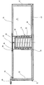
Im folgenden ist die erfindungsgemäße Ausgleichsvorrichtung anhand der einzigen Figur näher erläutert, wobei die Figur einen Längsschnitt durch die Ausgleichsvorrichtung in ihrer Einbaulage zeigt.The compensation device according to the invention is explained in more detail below with reference to the single figure, the figure showing a longitudinal section through the compensation device in its installed position.
Die erfindungsgemäße Ausgleichsvorrichtung weist einen Ausgleichsbehälter 10 auf, der in seinem unteren Randbereich mit einem Anschlußstück 12 versehen ist, das dem Anschluß an eine fluidführende Leitung (nicht dargestellt) dient, die das Innere des Ausgleichsbehälters 10 mit dem Inneren des Transformator-Gehäuses (nicht dargestellt) verbindet. In dem Ausgleichsbehälter 10 ist eine mittels einer als Ganzes mit 14 bezeichneten Führungseinrichtung längs einer Verstellachse 16 verfahrbare Ausgleichsplatte 18 angeordnet, die unter der Einwirkung eines Kraftspeichers in Form einer Druck-Schraubenfeder 20 in Anlage mit dem im Ausgleichsbehälter aufgenommenen Trafoöl (nicht dargestellt) ist.The compensating device according to the invention has a
Die Ausgleichsplatte 18 ist mit einem Ende eines Faltenbalges 22 verbunden, der vorzugsweise aus einem Edelstahlblech gebildet ist. Das andere obere Ende des Faltenbalges 22 ist mit feststehenden Teilen des Ausgleichsbehälters in Form eines oberen Abschlußdeckels 24 verbunden. Die Ausgleichsplatte 18 begrenzt dabei mit dem Faltenbalg 22 innerhalb des Ausgleichsbehälters 10 ein Luftvolumen. Für einen Druckausgleich betreffend dieses einschließbare Luftvolumen ist an dem oberen Abschlußdeckel 24 eine Öffnung 26 vorgesehen und eine daran angeschlossene Zu- und Abfuhrleitung 28 mündet mit ihrem einen Ende in das Innere des Ausgleichsbehälters 10. Das andere Ende dieser Zu- und Abfuhrleitung 28 kann an eine Filtereinheit (nicht dargestellt) angeschlossen sein, um auszuschließen, daß gegebenenfalls mit Trafoöl verunreinigte Luft ungefiltert aus dem Ausgleichsbehälter austreten kann, beispielsweise wenn der Balg 22 versagen sollte.The
Die als Ganzes mit 14 bezeichnete Führungseinrichtung weist zwei gegeneinander verschiebbare zylindrische Hülsen 30, 32 auf, von denen die untere mit der Ausgleichsplatte 18 und die andere mit dem Abschlußdeckel 24 verbunden ist, wobei die innerhalb der unteren Hülse 32 geführte Hülse 30 mit einer Anschlagfläche 34 an der Ausgleichsplatte 18 zusammenwirkt. Im umgekehrten Fall kann jedoch auch die äußere Hülse 32 derart axial nach oben weitergeführt sein, daß sie bei einem Zusammendrücken der Druckfeder 20 bei entsprechend einströmendem Trafoöl in den Ausgleichsbehälter 10 an der unteren Anschlagfläche gebildet durch die Unterseite des Abschlußdeckels 24 zum Schutz des Faltenbalges 22 anstößt. Die beiden Hülsen 30,32 sind darüber hinaus mit einem vorgebbaren Spiel gegeneinander verschiebbar angeordnet. Die obere Hülse 30, die in einen Durchlaß 36 der Ausgleichsplatte 24 eingreift, ist gegenüber dieser mittels einer Dichtplatte 38 gegenüber der Umgebung abgedichtet. Neben dem oberen Gehäusedeckel 24 weist die Ausgleichsvorrichtung auch einen unteren Gehäusedeckel 40 auf, die beide randseitig von einem Gehäusemantel 42 umschlossen sind, wobei dieser Gehäusemantel 42 den Faltenbalg 22 randseitig mit einem vorgebbaren Abstand umfaßt, so daß zwischen der Ausgleichsplatte 18 und dem weiteren Abschlußdeckel 40 die fluidführende Verbindung in Form einer Leitung (nicht dargestellt) über das Anschlußstück 12 in den Ausgleichsbehälter 10 mündet. Das Trafoöl 10 ist also über die Ausgleichsplatte 18 und den Faltenbalg 22 von der Luftseite des Ausgleichsbehälters 10 getrennt und ein Durchtritt des Trafoöles, meist in Form von Silikonöl, auf die Luftseite des Ausgleichsbehälters 10 ist ausgeschlossen.The guide device designated as a whole with 14 has two mutually displaceable
Wird betriebsbedingt Trafoöl über das Anschlußstück 12 in das Innere des Ausgleichsbehälters 10 geleitet, wird die Druckfeder 20 um einen entsprechend dem zugeführten Volumen vorgegebenen Betrag zusammengedrückt und die Ausgleichsplatte 18 bewegt sich in der Figur gesehen längs ihrer Verstellachse 16 nach oben, wobei der Faltenbalg 22 um dieselbe Wegstrecke zusammengedrückt wird. Das im Ausgleichsbehälter 10 innerhalb des Faltenbalges 22 aufgenommene Luftvolumen wird um den Betrag des eingeströmten Trafoöles verringert und strömt über die Öffnung 26 und die Zu- und Ablaufleitung 28 ab. Um einer Beschädigung des Faltenbalges 22 entgegenzuwirken, ist eine maximal vorgesehene Verstellstrecke vorgesehen, die beendet ist, wenn die Unterseite der innen geführten Hülse 30 an die Anschlagfläche 34 der Ausgleichsplatte 18 anstößt. Wird innerhalb des Transformators Trafoöl benötigt, bewirken die anstehenden Druckverhältnisse im Anschlußstück 12, daß die Druckfeder 20 sich entspannt und über die Ausgleichsplatte 18 wird das Transformatorenöl dem Gehäuse des Transformators zugeführt. Mit der erfindungsgemäßen Ausgleichsvorrichtung sind dynamische Wechsel beim Zu- und Abführen des Transformatorenöles möglich. Aufgrund des ausgeübten Druckes mittels des Kraftspeichers in Form der Druckfeder 20 läßt sich die Ausgleichsvorrichtung auch unterhalb des Transformators im Unterflurbereich eines Schienenfahrzeuges anordnen und von dort läßt sich der Fluidvorrat abrufen.If transformer oil is passed through the
Claims (7)
Applications Claiming Priority (2)
| Application Number | Priority Date | Filing Date | Title |
|---|---|---|---|
| DE19517401A DE19517401C1 (en) | 1995-05-15 | 1995-05-15 | Equalisation device for rail locomotive transformer |
| DE19517401 | 1995-05-15 |
Publications (3)
| Publication Number | Publication Date |
|---|---|
| EP0743661A2 true EP0743661A2 (en) | 1996-11-20 |
| EP0743661A3 EP0743661A3 (en) | 1996-12-27 |
| EP0743661B1 EP0743661B1 (en) | 1999-06-02 |
Family
ID=7761716
Family Applications (1)
| Application Number | Title | Priority Date | Filing Date |
|---|---|---|---|
| EP96105262A Expired - Lifetime EP0743661B1 (en) | 1995-05-15 | 1996-04-02 | Compensation device |
Country Status (9)
| Country | Link |
|---|---|
| US (1) | US5709289A (en) |
| EP (1) | EP0743661B1 (en) |
| JP (1) | JPH08321422A (en) |
| AT (1) | ATE180921T1 (en) |
| DE (2) | DE19517401C1 (en) |
| DK (1) | DK0743661T3 (en) |
| ES (1) | ES2135128T3 (en) |
| GR (1) | GR3030409T3 (en) |
| NO (1) | NO961957L (en) |
Cited By (2)
| Publication number | Priority date | Publication date | Assignee | Title |
|---|---|---|---|---|
| WO2000022633A1 (en) | 1998-10-14 | 2000-04-20 | Hydac Technology Gmbh | Compensating device suitable for use in railway car transformers |
| US10150474B2 (en) * | 2017-01-04 | 2018-12-11 | Robert Bosch Gmbh | Reducing lateral position deviation during an automated lane change |
Families Citing this family (5)
| Publication number | Priority date | Publication date | Assignee | Title |
|---|---|---|---|---|
| US6317286B1 (en) | 1999-01-29 | 2001-11-13 | Seagate Technology Llc | Diaphragm-sealed disc drive |
| US6271470B1 (en) | 2000-01-12 | 2001-08-07 | Abb Power T&D Company Inc. | Oil filled power bushing with piston |
| US6624736B1 (en) | 2000-05-19 | 2003-09-23 | Abb Inc. | Fuse housing with rate release control plug |
| CN106328344B (en) * | 2014-06-23 | 2018-08-31 | 上海联影医疗科技有限公司 | Ct apparatus |
| CN114623386B (en) * | 2022-03-10 | 2023-12-22 | 东营晨辉机械制造有限公司 | Dual-channel sleeve pressing seat with pressure protection function for oil extraction in oil field |
Citations (2)
| Publication number | Priority date | Publication date | Assignee | Title |
|---|---|---|---|---|
| JPS56162815A (en) * | 1980-05-20 | 1981-12-15 | Tamura Seisakusho Co Ltd | Bellows device |
| JPS607108A (en) * | 1983-06-24 | 1985-01-14 | Mitsubishi Electric Corp | Oil-filled electric apparatus |
Family Cites Families (9)
| Publication number | Priority date | Publication date | Assignee | Title |
|---|---|---|---|---|
| DD62621A (en) * | ||||
| DD62619A (en) * | ||||
| DE62621C (en) * | H. WEVELSHÜTTEN in Brünen b. Wesel | Brake on clockworks for operating churns | ||
| DE62619C (en) * | F. H. WHEELAN in Santa Barbara, Grfsch. Santa Barbara, Staat California, V. St. A | Device for separating materials according to their different surface properties | ||
| US2703108A (en) * | 1950-12-04 | 1955-03-01 | Tommy J Mccuistion | Accumulator |
| US3670276A (en) * | 1971-02-11 | 1972-06-13 | Ltv Ling Altec Inc | Hermetic transformer |
| US4225111A (en) * | 1976-11-03 | 1980-09-30 | Corcordia Fluidtechnik Gmbh | Solenoid valve |
| NO152382C (en) * | 1983-06-06 | 1985-09-18 | Myrens Verksted As | fluid accumulator |
| DE3800945C1 (en) * | 1988-01-15 | 1989-02-16 | Daimler-Benz Ag, 7000 Stuttgart, De |
-
1995
- 1995-05-15 DE DE19517401A patent/DE19517401C1/en not_active Expired - Fee Related
-
1996
- 1996-04-02 ES ES96105262T patent/ES2135128T3/en not_active Expired - Lifetime
- 1996-04-02 DE DE59602056T patent/DE59602056D1/en not_active Expired - Fee Related
- 1996-04-02 AT AT96105262T patent/ATE180921T1/en not_active IP Right Cessation
- 1996-04-02 DK DK96105262T patent/DK0743661T3/en active
- 1996-04-02 EP EP96105262A patent/EP0743661B1/en not_active Expired - Lifetime
- 1996-04-26 US US08/638,236 patent/US5709289A/en not_active Expired - Lifetime
- 1996-05-14 NO NO961957A patent/NO961957L/en unknown
- 1996-05-14 JP JP8119145A patent/JPH08321422A/en not_active Ceased
-
1999
- 1999-06-03 GR GR990401447T patent/GR3030409T3/en unknown
Patent Citations (2)
| Publication number | Priority date | Publication date | Assignee | Title |
|---|---|---|---|---|
| JPS56162815A (en) * | 1980-05-20 | 1981-12-15 | Tamura Seisakusho Co Ltd | Bellows device |
| JPS607108A (en) * | 1983-06-24 | 1985-01-14 | Mitsubishi Electric Corp | Oil-filled electric apparatus |
Non-Patent Citations (2)
| Title |
|---|
| PATENT ABSTRACTS OF JAPAN vol. 006, no. 047 (E-099), 26.März 1982 & JP-A-56 162815 (TAMURA SEISAKUSHO CO LTD), 15.Dezember 1981, * |
| PATENT ABSTRACTS OF JAPAN vol. 009, no. 118 (E-316), 23.Mai 1985 & JP-A-60 007108 (MITSUBISHI DENKI KK), 14.Januar 1985, * |
Cited By (4)
| Publication number | Priority date | Publication date | Assignee | Title |
|---|---|---|---|---|
| WO2000022633A1 (en) | 1998-10-14 | 2000-04-20 | Hydac Technology Gmbh | Compensating device suitable for use in railway car transformers |
| DE19847313A1 (en) * | 1998-10-14 | 2000-05-04 | Hydac Technology Gmbh | Compensating device, suitable for use in transformers of rail vehicles |
| US6549110B1 (en) | 1998-10-14 | 2003-04-15 | Hydac Technology Gmbh | Compensating device suitable for use in railway car transformers |
| US10150474B2 (en) * | 2017-01-04 | 2018-12-11 | Robert Bosch Gmbh | Reducing lateral position deviation during an automated lane change |
Also Published As
| Publication number | Publication date |
|---|---|
| EP0743661A3 (en) | 1996-12-27 |
| DE19517401C1 (en) | 1996-09-26 |
| ES2135128T3 (en) | 1999-10-16 |
| NO961957L (en) | 1996-11-18 |
| NO961957D0 (en) | 1996-05-14 |
| EP0743661B1 (en) | 1999-06-02 |
| GR3030409T3 (en) | 1999-09-30 |
| ATE180921T1 (en) | 1999-06-15 |
| US5709289A (en) | 1998-01-20 |
| JPH08321422A (en) | 1996-12-03 |
| DE59602056D1 (en) | 1999-07-08 |
| DK0743661T3 (en) | 1999-12-13 |
Similar Documents
| Publication | Publication Date | Title |
|---|---|---|
| EP0874676B1 (en) | Filter device with a bypass valve | |
| EP0230529B1 (en) | Valve arrangement for hydraulic accumulator | |
| EP0743661B1 (en) | Compensation device | |
| DE2533164C3 (en) | Hydraulic control device for a hydraulic system | |
| EP1478559A1 (en) | Thrust piece unit for rack-steering gears | |
| EP2729229B1 (en) | Filter element for a filter device | |
| DE1557773C3 (en) | Control device for the hydraulically operated lifting device of an agricultural tractor. Eliminated from: 1482477 | |
| EP1629208A1 (en) | Proportional pressure control valve | |
| EP1119865B1 (en) | Compensating device suitable for use in railway car transformers | |
| EP2496426B1 (en) | Air spring having a control valve for residual pressure maintenance | |
| DE4035840C1 (en) | Circuit for differential pressure control between two chambers - ifcluding safety valve which is opened in any limiting values are exceeded | |
| DE102022002290A1 (en) | Filter element | |
| DE102021005288A1 (en) | contraption | |
| DE19716979A1 (en) | Fuel supply system for vehicles | |
| DE102022204446A1 (en) | Filter device | |
| DE102021006456A1 (en) | hydraulic accumulator | |
| DE102017001540B4 (en) | Filter device, filter device housing and their use | |
| DE2113903C3 (en) | Flow rate control device for coolant and heating medium circuits in vehicles | |
| DE112021007096T5 (en) | FRONT FORK | |
| DE1925250A1 (en) | Diaphragm valve, in particular pressure reducing valve | |
| DE1925618C (en) | Filter arrangement | |
| DE855271C (en) | Distribution valve device for pressure medium brakes | |
| DE2924530A1 (en) | FLOW CONTROL VALVE FOR FLUIDS | |
| EP2019941A1 (en) | Control valve for removing liquid | |
| EP0909884A1 (en) | Pressure control valve |
Legal Events
| Date | Code | Title | Description |
|---|---|---|---|
| PUAI | Public reference made under article 153(3) epc to a published international application that has entered the european phase |
Free format text: ORIGINAL CODE: 0009012 |
|
| PUAL | Search report despatched |
Free format text: ORIGINAL CODE: 0009013 |
|
| AK | Designated contracting states |
Kind code of ref document: A2 Designated state(s): AT BE CH DE DK ES FI FR GB GR IE IT LI LU NL PT SE |
|
| AK | Designated contracting states |
Kind code of ref document: A3 Designated state(s): AT BE CH DE DK ES FI FR GB GR IE IT LI LU NL PT SE |
|
| 17P | Request for examination filed |
Effective date: 19970127 |
|
| 17Q | First examination report despatched |
Effective date: 19970313 |
|
| GRAG | Despatch of communication of intention to grant |
Free format text: ORIGINAL CODE: EPIDOS AGRA |
|
| GRAG | Despatch of communication of intention to grant |
Free format text: ORIGINAL CODE: EPIDOS AGRA |
|
| GRAH | Despatch of communication of intention to grant a patent |
Free format text: ORIGINAL CODE: EPIDOS IGRA |
|
| GRAH | Despatch of communication of intention to grant a patent |
Free format text: ORIGINAL CODE: EPIDOS IGRA |
|
| GRAA | (expected) grant |
Free format text: ORIGINAL CODE: 0009210 |
|
| AK | Designated contracting states |
Kind code of ref document: B1 Designated state(s): AT BE CH DE DK ES FI FR GB GR IE IT LI LU NL PT SE |
|
| REF | Corresponds to: |
Ref document number: 180921 Country of ref document: AT Date of ref document: 19990615 Kind code of ref document: T |
|
| ET | Fr: translation filed | ||
| REG | Reference to a national code |
Ref country code: CH Ref legal event code: NV Representative=s name: ISLER & PEDRAZZINI AG Ref country code: CH Ref legal event code: EP |
|
| REF | Corresponds to: |
Ref document number: 59602056 Country of ref document: DE Date of ref document: 19990708 |
|
| REG | Reference to a national code |
Ref country code: IE Ref legal event code: FG4D Free format text: GERMAN |
|
| GBT | Gb: translation of ep patent filed (gb section 77(6)(a)/1977) |
Effective date: 19990708 |
|
| REG | Reference to a national code |
Ref country code: ES Ref legal event code: FG2A Ref document number: 2135128 Country of ref document: ES Kind code of ref document: T3 |
|
| REG | Reference to a national code |
Ref country code: PT Ref legal event code: SC4A Free format text: AVAILABILITY OF NATIONAL TRANSLATION Effective date: 19990901 |
|
| REG | Reference to a national code |
Ref country code: DK Ref legal event code: T3 |
|
| PGFP | Annual fee paid to national office [announced via postgrant information from national office to epo] |
Ref country code: IE Payment date: 20000321 Year of fee payment: 5 |
|
| PG25 | Lapsed in a contracting state [announced via postgrant information from national office to epo] |
Ref country code: DK Free format text: LAPSE BECAUSE OF NON-PAYMENT OF DUE FEES Effective date: 20000402 |
|
| PG25 | Lapsed in a contracting state [announced via postgrant information from national office to epo] |
Ref country code: ES Free format text: LAPSE BECAUSE OF NON-PAYMENT OF DUE FEES Effective date: 20000403 |
|
| PGFP | Annual fee paid to national office [announced via postgrant information from national office to epo] |
Ref country code: LU Payment date: 20000403 Year of fee payment: 5 |
|
| PGFP | Annual fee paid to national office [announced via postgrant information from national office to epo] |
Ref country code: FI Payment date: 20000404 Year of fee payment: 5 |
|
| PLBE | No opposition filed within time limit |
Free format text: ORIGINAL CODE: 0009261 |
|
| STAA | Information on the status of an ep patent application or granted ep patent |
Free format text: STATUS: NO OPPOSITION FILED WITHIN TIME LIMIT |
|
| PGFP | Annual fee paid to national office [announced via postgrant information from national office to epo] |
Ref country code: BE Payment date: 20000413 Year of fee payment: 5 |
|
| PGFP | Annual fee paid to national office [announced via postgrant information from national office to epo] |
Ref country code: NL Payment date: 20000428 Year of fee payment: 5 |
|
| PG25 | Lapsed in a contracting state [announced via postgrant information from national office to epo] |
Ref country code: GR Free format text: LAPSE BECAUSE OF NON-PAYMENT OF DUE FEES Effective date: 20000430 |
|
| 26N | No opposition filed | ||
| PG25 | Lapsed in a contracting state [announced via postgrant information from national office to epo] |
Ref country code: PT Free format text: LAPSE BECAUSE OF NON-PAYMENT OF DUE FEES Effective date: 20001031 |
|
| REG | Reference to a national code |
Ref country code: DK Ref legal event code: EBP |
|
| REG | Reference to a national code |
Ref country code: PT Ref legal event code: MM4A Free format text: LAPSE DUE TO NON-PAYMENT OF FEES Effective date: 20001031 |
|
| PGFP | Annual fee paid to national office [announced via postgrant information from national office to epo] |
Ref country code: GB Payment date: 20010302 Year of fee payment: 6 |
|
| PGFP | Annual fee paid to national office [announced via postgrant information from national office to epo] |
Ref country code: FR Payment date: 20010329 Year of fee payment: 6 |
|
| PG25 | Lapsed in a contracting state [announced via postgrant information from national office to epo] |
Ref country code: LU Free format text: LAPSE BECAUSE OF NON-PAYMENT OF DUE FEES Effective date: 20010402 Ref country code: IE Free format text: LAPSE BECAUSE OF NON-PAYMENT OF DUE FEES Effective date: 20010402 Ref country code: FI Free format text: LAPSE BECAUSE OF NON-PAYMENT OF DUE FEES Effective date: 20010402 |
|
| PGFP | Annual fee paid to national office [announced via postgrant information from national office to epo] |
Ref country code: CH Payment date: 20010427 Year of fee payment: 6 Ref country code: AT Payment date: 20010427 Year of fee payment: 6 |
|
| PG25 | Lapsed in a contracting state [announced via postgrant information from national office to epo] |
Ref country code: BE Free format text: LAPSE BECAUSE OF NON-PAYMENT OF DUE FEES Effective date: 20010430 |
|
| BERE | Be: lapsed |
Owner name: HYDAC TECHNOLOGY G.M.B.H. Effective date: 20010430 |
|
| PG25 | Lapsed in a contracting state [announced via postgrant information from national office to epo] |
Ref country code: NL Free format text: LAPSE BECAUSE OF NON-PAYMENT OF DUE FEES Effective date: 20011101 |
|
| REG | Reference to a national code |
Ref country code: GB Ref legal event code: IF02 |
|
| NLV4 | Nl: lapsed or anulled due to non-payment of the annual fee |
Effective date: 20011101 |
|
| REG | Reference to a national code |
Ref country code: IE Ref legal event code: MM4A |
|
| PG25 | Lapsed in a contracting state [announced via postgrant information from national office to epo] |
Ref country code: GB Free format text: LAPSE BECAUSE OF NON-PAYMENT OF DUE FEES Effective date: 20020402 Ref country code: AT Free format text: LAPSE BECAUSE OF NON-PAYMENT OF DUE FEES Effective date: 20020402 |
|
| PG25 | Lapsed in a contracting state [announced via postgrant information from national office to epo] |
Ref country code: LI Free format text: LAPSE BECAUSE OF NON-PAYMENT OF DUE FEES Effective date: 20020430 Ref country code: CH Free format text: LAPSE BECAUSE OF NON-PAYMENT OF DUE FEES Effective date: 20020430 |
|
| GBPC | Gb: european patent ceased through non-payment of renewal fee |
Effective date: 20020402 |
|
| REG | Reference to a national code |
Ref country code: CH Ref legal event code: PL |
|
| PG25 | Lapsed in a contracting state [announced via postgrant information from national office to epo] |
Ref country code: FR Free format text: LAPSE BECAUSE OF NON-PAYMENT OF DUE FEES Effective date: 20021231 |
|
| REG | Reference to a national code |
Ref country code: FR Ref legal event code: ST |
|
| PGFP | Annual fee paid to national office [announced via postgrant information from national office to epo] |
Ref country code: SE Payment date: 20030318 Year of fee payment: 8 |
|
| PG25 | Lapsed in a contracting state [announced via postgrant information from national office to epo] |
Ref country code: SE Free format text: LAPSE BECAUSE OF NON-PAYMENT OF DUE FEES Effective date: 20040403 |
|
| REG | Reference to a national code |
Ref country code: ES Ref legal event code: FD2A Effective date: 20010514 |
|
| EUG | Se: european patent has lapsed | ||
| PG25 | Lapsed in a contracting state [announced via postgrant information from national office to epo] |
Ref country code: IT Free format text: LAPSE BECAUSE OF NON-PAYMENT OF DUE FEES;WARNING: LAPSES OF ITALIAN PATENTS WITH EFFECTIVE DATE BEFORE 2007 MAY HAVE OCCURRED AT ANY TIME BEFORE 2007. THE CORRECT EFFECTIVE DATE MAY BE DIFFERENT FROM THE ONE RECORDED. Effective date: 20050402 |
|
| PGFP | Annual fee paid to national office [announced via postgrant information from national office to epo] |
Ref country code: DE Payment date: 20080508 Year of fee payment: 13 |
|
| PG25 | Lapsed in a contracting state [announced via postgrant information from national office to epo] |
Ref country code: DE Free format text: LAPSE BECAUSE OF NON-PAYMENT OF DUE FEES Effective date: 20091103 |