EP0743442B1 - Cylinder cooling apparatus of multi-cylinder engine - Google Patents
Cylinder cooling apparatus of multi-cylinder engine Download PDFInfo
- Publication number
- EP0743442B1 EP0743442B1 EP96103144A EP96103144A EP0743442B1 EP 0743442 B1 EP0743442 B1 EP 0743442B1 EP 96103144 A EP96103144 A EP 96103144A EP 96103144 A EP96103144 A EP 96103144A EP 0743442 B1 EP0743442 B1 EP 0743442B1
- Authority
- EP
- European Patent Office
- Prior art keywords
- cylinder
- cooling water
- water passage
- forming member
- passage forming
- Prior art date
- Legal status (The legal status is an assumption and is not a legal conclusion. Google has not performed a legal analysis and makes no representation as to the accuracy of the status listed.)
- Expired - Lifetime
Links
- 238000001816 cooling Methods 0.000 title claims description 17
- 239000000498 cooling water Substances 0.000 claims description 100
- XLYOFNOQVPJJNP-UHFFFAOYSA-N water Substances O XLYOFNOQVPJJNP-UHFFFAOYSA-N 0.000 claims description 76
- 238000004891 communication Methods 0.000 claims description 67
- 238000005266 casting Methods 0.000 claims description 20
- 230000006698 induction Effects 0.000 claims description 17
- 238000003892 spreading Methods 0.000 claims description 2
- 238000010276 construction Methods 0.000 description 14
- 238000003466 welding Methods 0.000 description 11
- 239000002184 metal Substances 0.000 description 9
- 238000003754 machining Methods 0.000 description 4
- 238000009835 boiling Methods 0.000 description 3
- 238000002485 combustion reaction Methods 0.000 description 3
- 230000003247 decreasing effect Effects 0.000 description 3
- 230000003014 reinforcing effect Effects 0.000 description 3
- 239000004576 sand Substances 0.000 description 3
- 238000007789 sealing Methods 0.000 description 3
- 238000004904 shortening Methods 0.000 description 3
- 238000003763 carbonization Methods 0.000 description 2
- 238000005516 engineering process Methods 0.000 description 2
- 239000000446 fuel Substances 0.000 description 2
- 238000005461 lubrication Methods 0.000 description 2
- 230000006835 compression Effects 0.000 description 1
- 238000007906 compression Methods 0.000 description 1
- 238000005520 cutting process Methods 0.000 description 1
- 238000005495 investment casting Methods 0.000 description 1
- 238000004519 manufacturing process Methods 0.000 description 1
Images






Classifications
-
- F—MECHANICAL ENGINEERING; LIGHTING; HEATING; WEAPONS; BLASTING
- F02—COMBUSTION ENGINES; HOT-GAS OR COMBUSTION-PRODUCT ENGINE PLANTS
- F02F—CYLINDERS, PISTONS OR CASINGS, FOR COMBUSTION ENGINES; ARRANGEMENTS OF SEALINGS IN COMBUSTION ENGINES
- F02F1/00—Cylinders; Cylinder heads
- F02F1/02—Cylinders; Cylinder heads having cooling means
- F02F1/10—Cylinders; Cylinder heads having cooling means for liquid cooling
- F02F1/108—Siamese-type cylinders, i.e. cylinders cast together
-
- F—MECHANICAL ENGINEERING; LIGHTING; HEATING; WEAPONS; BLASTING
- F02—COMBUSTION ENGINES; HOT-GAS OR COMBUSTION-PRODUCT ENGINE PLANTS
- F02F—CYLINDERS, PISTONS OR CASINGS, FOR COMBUSTION ENGINES; ARRANGEMENTS OF SEALINGS IN COMBUSTION ENGINES
- F02F1/00—Cylinders; Cylinder heads
- F02F1/02—Cylinders; Cylinder heads having cooling means
- F02F1/10—Cylinders; Cylinder heads having cooling means for liquid cooling
Definitions
- the present invention relates to a cylinder cooling apparatus of a multi-cylinder engine, and more specifically to a technology of embedding a chaplet for constructing a water passage forming member in a connection wall between adjacent cylinder bores of a multi-cylinder engine by the casting process so as to intensively cool a head side portion of the connection wall by making the cooling water flow through the water passage forming member.
- Figs. 10(A), 10(B) and 10(C) show the first conventional example;
- Fig. 10(A) is a vertical sectional view of a principal portion of the multi-cylinder thereof;
- Fig. 10(B) is a horizontal sectional plan view taken along the B - B directed line in Fig. 10(A);
- Fig. 10(C) is a perspective view of a water passage forming member embedded by the casting process in a connection wall between adjacent bores of the multi-cylinder.
- a plurality of cylinders 53 are arranged side by side in a front and rear direction in a cylinder block 51, a multi-cylinder 52 is constructed by connecting the adjacent cylinders 53, 53 to each other through a connection wall 54, cylinder jackets 58 are formed so as to enclose the multi-cylinder 52, and a water passage forming member 110 is embedded in the connection wall 54 by the casting process.
- a connection wall 54 As shown in Figs.
- the water passage forming member 110 is provided with a cooling water passage 115 which is vertically elongated and flat in its vertical sectional side view, and the cylinder jackets 58, 58 on the left and right opposed sides of the head side portion 54a are constructed so as to communicate with each other through the cooling water passage 115.
- the cylinder jackets 58, 58 are extended near to the left and right opposed outsides of the head side portion 54a of the connection wall 54, so that the cooling water inducted from one side of the cooling water passage 115 flows through the cooling water passage 115 to cool the head side portion 54a.
- bosses 55, 55 for a pair of left and right bolts 56, 56 for use in the tightening of a cylinder head are disposed outside the cylinder jackets 58, 58.
- projecting engagement portions 114, 114 projected from the left and right opposed end portions of the water passage forming member 110 are used for reliably securing the water passage forming member 110 to a core for a cylinder jacket at the time of manufacturing the core.
- cooling water passage 115 is flat and longitudinally elongated, a portion corresponding to the cooling water passage 115 becomes short of strength when machining the cylinder bore 53a and, resultantly it is apprehended that local distortions might be produced in the cylinder bore 53a.
- Figs. 11(A), 11(B) and 11(C) show the second conventional example;
- Fig. 11(A) is a vertical sectional view of a principal portion of the multi-cylinder thereof;
- Fig. 11(B) is a horizontal sectional plan view taken along the B - B directed line in Fig. 11(A);
- Fig. 11(C) is a perspective view of a water passage forming member embedded in a connection wall of the multi-cylinder by the casting process.
- the water passage forming member 110 is provided with a pair of left and right vertical jacket communication passages 112, 112 for making left and right cylinder jackets 58, 58 within a cylinder block 51 communicate with a head jacket (not illustrated), a cooling water passages 115 for making the paired left and right jacket communication passages 112, 112 with each other and a pair of left and right cooling water induction portions 113, 113 disposed at the lower portions of the respective cylinder jacket communication passages 112, 112 and opened toward the respective cylinder jackets 58, 58.
- the cooling water inducted from the cooling water induction portions 113, 113 flows through the cooling water passage 115 and flows out into the head jacket (not illustrated) disposed above the head side portion 54a of the connection wall 54, through the jacket communication passages 112, 112 to cool the head side portion 54a meanwhile.
- the cylinder head tightening bosses 55, 55 disposed on the left and right sides of the head side portion 54a of the connection wall 54 are disposed outside the cylinder jackets 58, 58 similarly to the first conventional example.
- cooling water induction portions 113 are formed by cutting out the lower portions of the tubes which construct the respective jacket communication passages 112, openings of the cooling water induction portions 113 are small. Therefore, there exists a disadvantage that the head side portion 54a of the connection wall 54 can't be cooled intensively because a great deal of cooling water can't be smoothly inducted into the cooling water passage 115.
- cooling water passage 115 is flat and longitudinally elongated and thus the thickness of the connection wall 54 can't be reduced satisfactorily similarly to the first conventional example, there exists a difficulty in an intent to largely increase an output power of the engine by shortening a distance between the cylinder bores 53a or by increasing a stroke volume.
- Figs. 12(A), 12(B) and 12(C) show the third conventional example.
- Fig. 12(A) is a vertical sectional view of a principal portion of the multi-cylinder thereof.
- Fig. 12(B) is a horizontal sectional plan view taken along the B - B directed line in Fig. 12(A), and
- Fig. 12(C) is a perspective view of a water passage forming member embedded in a connection wall of the multi-cylinder by the casting process.
- a plurality of cylinders 53 are arranged side by side in a front and rear direction in a cylinder block 51, a multi-cylinder 52 is constructed by connecting the adjacent cylinders 53, 53 to each other through a connection wall 54, cylinder jackets 58 are formed so as to enclose the multi-cylinder 52, and a water passage forming member 110 is embedded in the connection wall 54 by the casting process.
- the water passage forming member 110 is provided with a pair of left and right jacket communication passages 112, 112, a pair of left and right cooling water induction openings 113, 113 formed in the lower portions of the respective jacket communication passages 112, 112 and opened toward the respective cylinder jackets 58, 58, and a pair of left and right cooling water passages 115 brought into communication with the respective jacket communication passages 112 and with the cooling water induction openings 113.
- These cooling water passages 115 are formed flat in the front view, elongated in the vertical sectional side view and like bags so as to make the cooling water within the cylinder jackets 58 flow out into the head jacket through the cooling water induction openings 113, the cooling water passages 115 and the jacket communication passages 112 orderly to cool the head-side portion 54a of the connection wall 54 meanwhile.
- the water passage forming member 110 is constructed by forming two sheet metal bodies 110a, 110a through a forming die and securing non-hollow portions 111, 111 each in the shape of horizontally directed H to each other. But joint portions 117 formed outside the left and right jacket communication passages 112, 112 are merely superposed one on another and not fixedly secured to each other.
- the two fore and rear sheet metal bodies 110a, 110a are not symmetrical because the joint portions 117 are different in configuration.
- the cooling water passages 115 are flat and vertically elongated and thus the thickness of the connection wall 54 can not be reduced satisfactorily similarly to the first conventional example, there exists a difficulty in an intent to largely increase an output power of the engine by shortening a distance between the cylinder bores 53a or to increase the stroke volume.
- the openings of the cooling water induction openings 113 are small similarly to the second conventional example, it is impossible to smoothly induct a great deal of cooling water into the cooling water passages 115.
- connection wall 54 since the thickness of the connection wall 54 can't be reduced satisfactorily, it is impossible to shorten the distance between the cylinder bores 53a. Further, there exists a disadvantage that the head side portion 54a of the connection wall 54 can't be cooled intensively. In this way, since the head side portion 54a of the connection wall 54 can't be cooled intensively, the increasing of the engine output power can't be accomplished due to the decreasing of radiating capability.
- a diesel engine needs a gas sealing pressure of at least about 900 Kg/cm 2 due to its high compression ratio.
- the distance between the cylinder head tightening bosses 55, 55 is large and thus the cylinders 53 can't be tightened uniformly and strongly along the circumferential direction, it is impossible to increase the gas sealing pressure sufficiently in the case of application to the diesel engine.
- US-A-5188071 discloses a cylinder cooling apparatus of a multi-cylinder engine having a water passage forming member embedded in a connection wall between adjacent bores of a multi-cylinder block by a casting process, wherein the water passage forming member is provided with vertical left and right jacket communication passages for communicating cylinder jackets within the multi-cylinder block with a head jacket and is provided with cooling water passages extending horizontally between the left and right jacket communication passages.
- the invention is characterised in that the water passage forming member has a plurality of non-hollow portions between its uppermost and lowermost parts, each of the non-hollow portions extending horizontally from one of the jacket communication passages, there being a non-hollow portion both above and below each of the cooling water passages.
- the water passage forming member 10 is provided with a pair of left and right vertical jacket communication passages 12, 12 for bringing the cylinder jackets 8, 8 within the cylinder block 1 into communication with the head jacket 22, with cooling water passages 15 arranged vertically and in multiple cooling water passages 15 arranged vertically and in multiple stage for bringing the paired left and right jacket communication passages 12, 12 into communication with each other, and non-hollow portions 11 arranged in multiple stage and alternately with the cooling water passages 15.
- the non-hollow portions 11 formed vertically and in multiple stage in the water passage forming member 10 serve as ribs for mechanically reinforcing the connection wall 4. That is, the cooling water passages 15 formed vertically and in multiple stage as well as alternately with the non-hollow portions 11 increase the mechanical strength remarkably in comparison with the flat vertically elongated cooling water passage 115 of the conventional examples. Thereby, it is not apprehended that partial distortions are produced during the boring of the cylinder bore 3a.
- connection wall 4 Since the non-hollow portions 11 formed vertically and in multiple stage mechanically reinforce the connection wall 4, the water passage forming member 10 can be thinned to the utmost and as a result the connection wall 4 can be thinned to the utmost. Thereby, the distance between the cylinder bores can be shortened by making the thickness of the connection wall 4 thinner than those of the conventional examples. Otherwise, the increasing of the stroke volume and as a result the increasing of the output power can be accomplished by enlarging a diameter of the cylinder bore.
- the cooling water within the cylinder jackets 8, 8 flows smoothly along the cylinder external circumferential surface 3a and escapes into the head jacket 22 disposed above the connection wall 4, through the cooling water passages 15 and the jacket communication passages 12. Meanwhile, most of the cooling water flows through the cooling water passages 15 in the upper half portion to intensively cool the head side portion 4a.
- the piston rings can be cooled intensively through the cylinder wall. Thereby, it becomes possible to accomplish the increasing of the engine output power as follows.
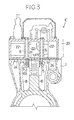
- Fig. 3 is a vertical sectional view of a principal portion of a vertical multi-cylinder engine having a water passage forming member according to the first embodiment of the present invention embedded therein by a casting process.
- a vertical multi-cylinder engine E has a cylinder head 20 fixedly secured by head bolts 6 onto a cylinder block 1 integrally formed with a crankcase, cylinder jackets 8 formed in the cylinder block 1 and a head jacket 22 formed in the cylinder head 20 being brought into communication with each other through many jacket communication ports 24 formed in portions except a connection wall 4 to cool the cylinder head 20 by the cooling water which has already cooled the cylinder block 1.
- a cylinder cooling apparatus of a multi-cylinder engine has a multi-cylinder 2 constructed by arranging a plurality of cylinders 3 in the cylinder block 1 side by side in a front and rear direction and connecting the adjacent cylinders 3, 3 through a connection wall 4, and also it has the cylinder jackets 8 formed so as to surround the multi-cylinder 2.
- the water passage forming member 10 to be explained later is embedded in the connection wall 4 by the casting process.
- the water passage forming member 10 is constructed by superposing two press-formed sheet metal bodies 10a, 10a one on another while facing each other and connecting their mutual joint portions by means of seam welding to form an integral construction. Thereby, it can be manufactured readily by merely securing the two sheet metal bodies 10a, 10a formed in the same configuration to each other.
- the water passage forming member 10 is provided with a pair of left and right vertical jacket communication passages 12, 12 for bringing cylinder jackets 8, 8 within a cylinder block 1 into communication with a head jacket 22, cooling water passages 15 arranged vertically and in multiple stage for bringing the paired left and right jacket communication passages 12, 12 into communication with each other, and non-hollow portions 11 arranged in multiple stage and alternately with the cooling water passages 15.
- the lower portions of the paired left and right jacket communication passages 12, 12 are formed as a pair of cooling water induction portions 13, 13 opened toward the respective cylinder jackets 8, 8, so that a great deal of cooling water inducted from the cooling water induction portions 13, 13 can flow through the cooling water passages 15 and flow out into the head jacket 22 disposed above the head side portion 4a through the jacket communication passages 12, 12.
- the non-hollow portions 11 and the cooling water passages 15 are formed vertically and in multiple stage as well as arranged alternately with each other as disclosed in the above-mentioned embodiment, the non-hollow portions 11 serve as ribs for mechanically reinforcing the connection wall 4 and provide such an advantage that they can effectively cope with a pressurizing force acting on the connection wall 4 during the machining of cylinder bores or the engine operation in comparison with the case where the cooling water passage 15 is formed longitudinally elongated and flat in the vertical sectional side view like that in the first conventional example.
- the plural cooling water passages 15 formed vertically and in multiple stage as well as alternately with the non-hollow portions 11 increase the mechanical strength remarkably in comparison with the flat longitudinally elongated cooling water passage 115 of the conventional example. Thereby, it is not apprehended that local distortions are produced during the boring of the cylinder bore 3a.
- the water passage forming member 10 can be thinned to the utmost and as a result the connection wall 4 can be thinned to the utmost.
- the distance between the cylinder bores can be shortened by reducing the thickness of the connection wall 4 more than that of the conventional example. Otherwise, the increasing of the stroke volume and as a result the increasing of the output power can be accomplished by enlarging a diameter of the cylinder bore.
- a pair of left and right cylinder head tightening bosses 5, 5 are formed continuously with the opposed left and right side portions of the head side portion 4a to narrow intervals between the head bolts 6, 6, so that the cylinders 3 can be tightened more uniformly and strongly by that narrowed amount along the circumferential direction.
- the present invention is not limited to this construction, when the pair of left and right cylinder head tightening bosses 5, 5 are formed continuously with the opposed left and right side portions of the head side portion 4a, advantageously it becomes possible to enlarge jacket communication ports 23 formed in the upper end wall of the cylinder block 1 and bores of the paired jacket communication passages 12, 12, thereby enabling a great deal of the cooling water to flow therethrough.
- the paired jacket communication passages 12, 12 are disposed inside of the bosses 5, 5 and are in communication with the jacket communication ports 23 formed in the upper end wall of the cylinder block 1 as well as in the lower end wall of the cylinder head 20. As shown in Figs. 1(A) and 1(B), a lateral dimension d of the cooling water passages 15 is set smaller than a lateral dimension D of the connection wall 4. Thereby, the interval d between the inside edges of the openings of the paired jacket communication passages 12, 12 can be set smaller than the lateral dimension D of the connection wall 4.
- the interval between the paired left and right head bolts 6, 6 can be narrowed by that narrowed amount of the interval d between the inside edges of the openings of the jacket communication passages 12, 12 to increase the number of the head bolts 6 arranged around the cylinder 3, it becomes possible to tighten the cylinders 3 more uniformly and strongly along the circumferential direction thereof. Thereby, it becomes possible to increase the gas sealing pressure.
- the paired left and right cooling water induction portions 13, 13 are constructed by spreading a pair of fore and rear cooling water guide plates 14, 14 projected leftward and rightward, along the respective external circumferential surfaces 3a, 3a of the adjacent fore and rear cylinders 3, 3 respectively. Since openings of the cooling water induction portions 13, 13 can be formed large by the above-mentioned construction, most of the cooling water flows into the cooling water passages 15 and the jacket communication passages 12 from the cooling water induction portions 13, 13 spread toward the cylinder jackets 8, 8 and then escapes into the head jacket 22 disposed above the connection wall 4, through the jacket communication passages 12, 12.
- the piston ring can be cooled intensively through the cylinder wall by cooling the head side portion 4a intensively, it becomes possible to relocate the top ring nearer to the piston top surface as much as possible and to reduce the annular dead space as much as possible which exists around the external circumference of the piston top portion and which doesn't contribute to the combustion, thereby improving the air utilizing ratio.
- the position of the piston pin can be relocated nearer to the piston top surface as much as possible to enlarge a rotation radius of a crank shaft correspondingly by that neared length. Therefore, it becomes possible to accomplish the relative downsizing of the connecting rod engine without modifying the engine physique and the increasing of the engine output power by enlarging the piston stroke. Since the head side portion 4a can be cooled intensively, it becomes also possible to accomplish the increasing of the stroke volume by enlarging the diameter of the cylinder bore. Further, when the present invention is also applied to a multi-cylinder engine or the like equipped with a turbocharger, it becomes possible to accomplish the relative downsizing and the increasing of the engine output power.
- Figs. 4(A), 4(B) and 4(C) show a water passage forming member according to the second embodiment of the present invention
- Figs. 5(A) and 5(B) show the principal portion of the cylinder block in which the water passage forming member is embedded by the casting process.
- the water passage forming member 10 is formed into an integral construction by superposing two sheet metal bodies 10a, 10a, which are formed symmetrically in a front and rear direction by means of a press forming die, one on another while opposing each other and then securing the non-hollow portions 11, 11 arranged vertically and in multiple stage to one another and also vertical outer edge joint portions 17, 17 projected outward from the outer edges of the left and right jacket communication passages 12, 12 to one another by means of seam welding.
- Constructions of the second embodiment different from those of the first embodiment will be explained hereinafter, and redundant explanations about common constructions thereof will be omitted.
- the cooling water passages 15 have hollow portions 15a having wedge-like configurations in the plan view and formed symmetrically in a left and right direction so that their leading ends face the middles of the passages 15.
- connection wall 4 is smallest at its mid portion and largest at its opposed end portions, when the cooling water passages 15 are formed in the wedge-like configuration in the plan view corresponding to the thickness of the connection wall 4 and symmetrically in the left and right direction so that their leading ends face the middles of the passages 15, the water passage forming member 10 can be thinned to the utmost and as a result the connection wall 4 can be thinned to the utmost.
- the distance between the cylinder bores can be shortened by reducing the thickness of the connection wall 4 more than those of the conventional examples. Otherwise, the increasing of the stroke volume and as a result the increasing of the output power can be accomplished by enlarging the diameter of the cylinder bore.
- the paired left and right cooling water passages 15 are formed acclivously outward at their upper edges 15b in the left and right directions. That is, even when steam is generated by the boiling of the cooling water within the respective cooling water passages 15, the steam moves upward along the acclivous upper edges 15b of the respective cooling water passages 15 to escape into the head jacket 22 through the jacket communication passages 12. Thereby, the cooling performance can be maintained at a high level.
- One of outer edge joint portions 17 formed at the outer edges of the jacket communication passages 12, 12 is embedded by the casting process eccentrically at a position nearer to one of the cylinders 3 between the one cylinder 3 and the one cylinder head tightening boss 5, and the other outer edge joint portions 17 is embedded by the casting process eccentrically at a position near to the other cylinder 3 between the other cylinder 3 and the other cylinder head tightening boss 5. That is, since an interval between the left and right cylinder head tightening bolts 6, 6 is constant, when the joint portions 17 are superposed one on another on the outsides of the left and right jacket communication passages 12, 12 like those in the conventional examples, a substantial cross sectional area of the jacket communication passage 12 becomes small. Thereupon, as mentioned above, when the outer edge joint portions 17, 17 are disposed eccentrically nearer to one of the cylinders 3, 3 and the other, respectively, it becomes possible to increase the substantial cross sectional area of the jacket communication passage 12.
- the paired jacket communication passages 12, 12 are disposed inside of the bosses 5, 5, and as shown in Fig. 5(A), they are in communication with the jacket communication ports 23 formed in the upper end wall of the cylinder block 1 and in the lower end wall of the cylinder head 20.
- the upper end portion of the jacket communication passage 12 is slightly higher than the non-hollow portion 11 at the upper edge thereof. This attempts to make sand cores 12b for use in forming the jacket communication ports 23 hardly break by setting the jacket communication ports 23 formed in the upper end wall of the cylinder block 1 relatively shorter.
- the symbol 16 in Fig. 4(A) designates a fore and rear wall connecting port of the connection wall 4.
- the non-hollow portion 11 of the present invention is not limited to one having the fore and rear wall connecting ports 16. But, when the fore and rear wall connecting ports 16 are provided, there appears an advantage that the connection wall 4 can more strongly cope with a pressurizing force acting thereon during the machining of the cylinder bore or the engine operation. Configurations of the fore and rear wall connecting port 16 will be explained later.
- Figs. 6(A) and 6(B) show a water passage forming member according to the third embodiment of the present invention
- Fig. 6(A) is a perspective view of the water passage forming member
- Fig. 6(B) is a vertical sectional front view of the water passage forming member.
- each of the paired left and right cooling water passages 15 acclivously outward in the left and right directions
- Figs. 7(A) and 7(B) show a water passage forming member according to the fourth embodiment of the present invention.
- Fig. 7(A) is a perspective view of the water passage forming member and
- Fig. 7(B) is a front view of the water passage forming member.
- the water passage forming member 10 is constructed as an integral unit by superposing two sheet metal bodies 10a, 10a symmetrically formed by means of a press forming die, one on another while opposing each other and securing vertical outer edge joint portions 17, 17 projected outward from the outer edges of the left and right jacket communication passages 12, 12 to each other by means of seam welding.
- the seam welding may be replaced with arc spot welding.
- fore and rear wall connecting ports 16 for connecting the fore and rear wall portions of the connection wall 4 to each other are opened in respective non-hollow portions 11, and the other constructions are the same as those in the second embodiment (Fig. 4(A)).
- non-hollow portions 11 have the fore and rear wall connecting ports 16 each formed like an elongated port, it becomes possible to more strongly cope with the pressurizing force acting on the connection wall 4 during the machining of the cylinder bore or the engine operation.
- the non-hollow portions 11 formed vertically and in multiple stage serve as ribs for mechanically reinforcing the connection wall 4, so that cooling water passages 15 formed vertically and in multiple stage as well as alternately with those non-hollow portions 11 can be improved remarkably in the mechanical strength when compared with the flat and vertically elongated cooling water passages 15 of the conventional examples. Thereby, it is not apprehended that local distortions are produced during the boring of the cylinder bore 3a.
- the cooling performance can be maintained at a high level. That is, even when steam is generated by the boiling of the cooling water within the respective cooling water passages 15, the steam moves upward along the acclivous upper edges 15b of the respective cooling water passages 15 and escapes into the head jacket 22 through the jacket communication passages 12. Thereby, the cooling performance can be maintained at a high level.
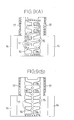
- Figs. 8(A) and 8(B) as well as Figs. 9(A) and 9(B) are front views showing variants of the water passage forming member according to the fourth embodiment.
- Fig. 8(A) shows a first variant of the water passage forming member.
- Fig. 8(B) shows a second variant of the water passage forming member.
- Fig. 9(A) shows a third variant of the water passage forming member
- Fig. 9(B) shows a fourth variant of the water passage forming member.
- the first variant is constructed by integrally securing the vertical outer edge joint portions 17, 17 projected outward from the outer edges of the left and right jacket communication passages 12, 12 to each other and the lower end non-hollow portions 11 to each other by means of seam welding respectively.
- the other constructions are the same as those in Fig. 7(A).
- the second variant is constructed by integrally securing the vertical outer edge joint portions 17, 17 projected outward from the outer edges of the left and right jacket communication passages 12, 12 to each other and the upper and lower end non-hollow portions 11, 11 to each other by means of seam welding respectively as well as by integrally securing the non-hollow portions 11, 11 to each other by means of arc spot welding.
- the fore and rear wall connecting ports 16 formed in the respective non-hollow portions 11 are formed by opening a plurality of round ports at certain intervals, and the other constructions are the same as those in Fig. 7(A). Since the non-hollow portions 11, 11 are integrally secured to each other by means of the arc spot welding as mentioned above, it becomes possible to prevent gaps from being formed by intrusion of foundry sand between the non-hollow portions 11, 11.
- the foundry sand is previously stuffed into the jacket communication passages 12 and the hollow portions 15 of the water passage forming member 10 under a pressure of the highly pressurized air.
- the non-hollow portions 11, 11 are not secured to each other, since the gaps are formed between the non-hollow portions 11, 11 by the intrusion of the foundry sand, there appears a problem that the thickness of the water passage forming member 10 becomes larger. This problem can be solved by integrally securing the non-hollow portions 11, 11 to each other by means of welding, so that the correct thickness of the water passage forming member 10 can be maintained.
- the non-hollow portions 11 formed vertically and in multiple stage are connected to vertical non-hollow portions 11b at the middle portions thereof.
- the fore and rear wall connecting ports 16 are formed as elongated ports in the respective non-hollow portions 11, and the other constructions are the same as those in Fig. 7(A).
- the paired left and right wedge-like cooling water passages 15 are partitioned by the vertical non-hollow portions 11b so as to be formed like bags each of which is shut off at the middle.
- the vertical outer edge joint portions 17, 17 projected outward from the outer edges of the left and right jacket communication passages 12, 12 are fixedly secured to each other by seam welding as well as the lower end non-hollow portions 11.
- a single round port is formed as the fore and rear wall connecting port 16 in each of the non-hollow portions 11, and the other constructions are the same as those in Fig. 7(A).
- the present invention is not limited to the above-mentioned embodiments and can be embodied in various ways by optional combination with the following components (a) to (j).
Landscapes
- Engineering & Computer Science (AREA)
- Chemical & Material Sciences (AREA)
- Combustion & Propulsion (AREA)
- Mechanical Engineering (AREA)
- General Engineering & Computer Science (AREA)
- Cylinder Crankcases Of Internal Combustion Engines (AREA)
Description
- The present invention relates to a cylinder cooling apparatus of a multi-cylinder engine, and more specifically to a technology of embedding a chaplet for constructing a water passage forming member in a connection wall between adjacent cylinder bores of a multi-cylinder engine by the casting process so as to intensively cool a head side portion of the connection wall by making the cooling water flow through the water passage forming member.
- Recently, there has been adopted a multi-cylinder engine in which a distance between adjacent cylinder bores is shortened because the downsizing and weight-decreasing is required for such multi-cylinder engines or in which a connection wall between adjacent cylinders is thinned as much as possible to enlarge cylinder bores because the increasing of a stroke volume is required to accomplish higher outputs of such engines.
- As for such a conventional technology, there have been known, for example a one (referred to as a first conventional example hereinafter) disclosed in the Japanese Patent Publication No. Sho 56-42744, a one (referred to as a second conventional example hereinafter) disclosed in the Japanese Utility Model Laid Open Publication No. Sho 59-68155, and a one (referred to as a third conventional example hereinafter) further disclosed in the Japanese Utility Model Laid Open Publication No. Sho 59-107946.
- Figs. 10(A), 10(B) and 10(C) show the first conventional example; Fig. 10(A) is a vertical sectional view of a principal portion of the multi-cylinder thereof; Fig. 10(B) is a horizontal sectional plan view taken along the B - B directed line in Fig. 10(A); and Fig. 10(C) is a perspective view of a water passage forming member embedded by the casting process in a connection wall between adjacent bores of the multi-cylinder.
- In this first conventional example, a plurality of
cylinders 53 are arranged side by side in a front and rear direction in acylinder block 51, a multi-cylinder 52 is constructed by connecting theadjacent cylinders connection wall 54,cylinder jackets 58 are formed so as to enclose the multi-cylinder 52, and a waterpassage forming member 110 is embedded in theconnection wall 54 by the casting process. As shown in Figs. 10(A), 10(B) and 10(C), the waterpassage forming member 110 is provided with acooling water passage 115 which is vertically elongated and flat in its vertical sectional side view, and thecylinder jackets head side portion 54a are constructed so as to communicate with each other through thecooling water passage 115. - As shown in Fig. 10(B), the
cylinder jackets head side portion 54a of theconnection wall 54, so that the cooling water inducted from one side of thecooling water passage 115 flows through thecooling water passage 115 to cool thehead side portion 54a. Incidentally,bosses right bolts cylinder jackets engagement portions passage forming member 110 are used for reliably securing the waterpassage forming member 110 to a core for a cylinder jacket at the time of manufacturing the core. - In the first conventional example, since the left and right opposed end portions and the
projecting engagement portions cooling water passage 115 are projected into thecylinder jackets circumferential surface 53b and also the flowing thereof into thecooling water passage 115. Therefore, there exists a disadvantage that thehead side portion 54a of theconnection wall 54 can not be cooled intensively by the cooling water. - Further, since the
cooling water passage 115 is flat and longitudinally elongated, a portion corresponding to thecooling water passage 115 becomes short of strength when machining the cylinder bore 53a and, resultantly it is apprehended that local distortions might be produced in thecylinder bore 53a. In order to avoid that, it is necessary to increase thickness of theconnection wall 54 to a certain extent. That is, since the thickness of theconnection wall 54 can not be reduced satisfactorily, there exists a difficulty in an intent to largely increase an output power of the engine by shortening a distance between thecylinder bores 53a or by increasing a stroke volume. - In addition, since the left and right cylinder
head tightening bosses cylinder jackets cylinders 53 can't be tightened strongly and uniformly along its circumferential direction because a distance between the left andright head bolts - Figs. 11(A), 11(B) and 11(C) show the second conventional example; Fig. 11(A) is a vertical sectional view of a principal portion of the multi-cylinder thereof; Fig. 11(B) is a horizontal sectional plan view taken along the B - B directed line in Fig. 11(A); and Fig. 11(C) is a perspective view of a water passage forming member embedded in a connection wall of the multi-cylinder by the casting process.
- As shown in Figs. 11(A), 11(B) and 11(C), the water
passage forming member 110 is provided with a pair of left and right verticaljacket communication passages right cylinder jackets cylinder block 51 communicate with a head jacket (not illustrated), acooling water passages 115 for making the paired left and rightjacket communication passages water induction portions jacket communication passages respective cylinder jackets - The cooling water inducted from the cooling
water induction portions cooling water passage 115 and flows out into the head jacket (not illustrated) disposed above thehead side portion 54a of theconnection wall 54, through thejacket communication passages head side portion 54a meanwhile. Incidentally, the cylinderhead tightening bosses head side portion 54a of theconnection wall 54 are disposed outside thecylinder jackets - In the above-mentioned second conventional example, though the cooling
water induction portions 113 are formed by cutting out the lower portions of the tubes which construct the respectivejacket communication passages 112, openings of the coolingwater induction portions 113 are small. Therefore, there exists a disadvantage that thehead side portion 54a of theconnection wall 54 can't be cooled intensively because a great deal of cooling water can't be smoothly inducted into thecooling water passage 115. - Further, since the
cooling water passage 115 is flat and longitudinally elongated and thus the thickness of theconnection wall 54 can't be reduced satisfactorily similarly to the first conventional example, there exists a difficulty in an intent to largely increase an output power of the engine by shortening a distance between thecylinder bores 53a or by increasing a stroke volume. - Moreover, since the left and right cylinder
head tightening bosses cylinder jackets cylinders 53 can be tightened strongly and uniformly along its circumferential direction because a distance between the left andright head bolts - Figs. 12(A), 12(B) and 12(C) show the third conventional example. Fig. 12(A) is a vertical sectional view of a principal portion of the multi-cylinder thereof. Fig. 12(B) is a horizontal sectional plan view taken along the B - B directed line in Fig. 12(A), and Fig. 12(C) is a perspective view of a water passage forming member embedded in a connection wall of the multi-cylinder by the casting process.
- Also in this third conventional example, a plurality of
cylinders 53 are arranged side by side in a front and rear direction in acylinder block 51, a multi-cylinder 52 is constructed by connecting theadjacent cylinders connection wall 54,cylinder jackets 58 are formed so as to enclose the multi-cylinder 52, and a waterpassage forming member 110 is embedded in theconnection wall 54 by the casting process. - As shown in Figs. 12(A), 12(B) and 12(C), the water
passage forming member 110 is provided with a pair of left and rightjacket communication passages water induction openings jacket communication passages respective cylinder jackets cooling water passages 115 brought into communication with the respectivejacket communication passages 112 and with the coolingwater induction openings 113. Thesecooling water passages 115 are formed flat in the front view, elongated in the vertical sectional side view and like bags so as to make the cooling water within thecylinder jackets 58 flow out into the head jacket through the coolingwater induction openings 113, thecooling water passages 115 and thejacket communication passages 112 orderly to cool the head-side portion 54a of theconnection wall 54 meanwhile. - The water
passage forming member 110 is constructed by forming twosheet metal bodies non-hollow portions joint portions 117 formed outside the left and rightjacket communication passages sheet metal bodies joint portions 117 are different in configuration. - In the third conventional example, since the
cooling water passages 115 are flat and vertically elongated and thus the thickness of theconnection wall 54 can not be reduced satisfactorily similarly to the first conventional example, there exists a difficulty in an intent to largely increase an output power of the engine by shortening a distance between thecylinder bores 53a or to increase the stroke volume. - Further, in the third conventional example, since the openings of the cooling
water induction openings 113 are small similarly to the second conventional example, it is impossible to smoothly induct a great deal of cooling water into thecooling water passages 115. - That is, in all of the first through third conventional examples, since the thickness of the
connection wall 54 can't be reduced satisfactorily, it is impossible to shorten the distance between thecylinder bores 53a. Further, there exists a disadvantage that thehead side portion 54a of theconnection wall 54 can't be cooled intensively. In this way, since thehead side portion 54a of theconnection wall 54 can't be cooled intensively, the increasing of the engine output power can't be accomplished due to the decreasing of radiating capability. - That is, though the piston rings are cooled through the cylinder wall, when the radiating capability of the
head side portion 54a is low, especially the top ring should be mounted a certain distance away from the piston top-surface in consideration of preventing the seizing and the like of the piston ring. This means that an annular dead space which doesn't contribute to combustion is provided around the external circumference of the piston top portion. Therefore, it is impossible to improve the air utilizing ratio, and resultantly it is also impossible to accomplish the increasing of the engine output power. - A diesel engine needs a gas sealing pressure of at least about 900 Kg/cm2 due to its high compression ratio. In all of the first through third conventional examples, since the distance between the cylinder
head tightening bosses cylinders 53 can't be tightened uniformly and strongly along the circumferential direction, it is impossible to increase the gas sealing pressure sufficiently in the case of application to the diesel engine. - Especially in recent years, it has been required to further promote the downsizing and weight decreasing of the engine and to accomplish the increasing of output power thereof. Since the first through third conventional examples have the above-mentioned disadvantages, they cannot answer these requirements satisfactorily. The present invention is directed to answering these requirements and has for its tasks
- a) to accomplish the further downsizing and weight decreasing of a multi-cylinder engine and the further increasing of the output power thereof by reducing the thickness of the connection wall to the utmost, and
- b) to improve the air utilizing ratio to accomplish the increasing of the engine output power by cooling the head side portion of the connection wall more intensively to relocate the top ring more upward of the piston
-
- The broadest claim hereinafter is characterised with respect to US-A-5188071, which discloses a cylinder cooling apparatus of a multi-cylinder engine having a water passage forming member embedded in a connection wall between adjacent bores of a multi-cylinder block by a casting process, wherein the water passage forming member is provided with vertical left and right jacket communication passages for communicating cylinder jackets within the multi-cylinder block with a head jacket and is provided with cooling water passages extending horizontally between the left and right jacket communication passages. The invention is characterised in that the water passage forming member has a plurality of non-hollow portions between its uppermost and lowermost parts, each of the non-hollow portions extending horizontally from one of the jacket communication passages, there being a non-hollow portion both above and below each of the cooling water passages.
- As will be described more fully with reference, for example, to Figures 1(A) and 1(B), in the cylinder cooling apparatus of the multi-cylinder engine having the above-mentioned fundamental construction, the water
passage forming member 10 is provided with a pair of left and right verticaljacket communication passages cylinder jackets cylinder block 1 into communication with thehead jacket 22, withcooling water passages 15 arranged vertically and in multiplecooling water passages 15 arranged vertically and in multiple stage for bringing the paired left and rightjacket communication passages non-hollow portions 11 arranged in multiple stage and alternately with thecooling water passages 15. - According to the present invention, the
non-hollow portions 11 formed vertically and in multiple stage in the waterpassage forming member 10 serve as ribs for mechanically reinforcing theconnection wall 4. That is, thecooling water passages 15 formed vertically and in multiple stage as well as alternately with thenon-hollow portions 11 increase the mechanical strength remarkably in comparison with the flat vertically elongatedcooling water passage 115 of the conventional examples. Thereby, it is not apprehended that partial distortions are produced during the boring of thecylinder bore 3a. - Since the
non-hollow portions 11 formed vertically and in multiple stage mechanically reinforce theconnection wall 4, the waterpassage forming member 10 can be thinned to the utmost and as a result theconnection wall 4 can be thinned to the utmost. Thereby, the distance between the cylinder bores can be shortened by making the thickness of theconnection wall 4 thinner than those of the conventional examples. Otherwise, the increasing of the stroke volume and as a result the increasing of the output power can be accomplished by enlarging a diameter of the cylinder bore. - The cooling water within the
cylinder jackets circumferential surface 3a and escapes into thehead jacket 22 disposed above theconnection wall 4, through thecooling water passages 15 and thejacket communication passages 12. Meanwhile, most of the cooling water flows through the coolingwater passages 15 in the upper half portion to intensively cool thehead side portion 4a. Thus, the piston rings can be cooled intensively through the cylinder wall. Thereby, it becomes possible to accomplish the increasing of the engine output power as follows. - a) Since the piston rings can be cooled intensively through the cylinder wall, it becomes possible to relocate the top ring nearer to the piston top surface as much as possible and to decrease an annular dead space around the external circumference of the piston top portion, which does not contribute to combustion, as much as possible to improve the air utilizing ratio. Further, along with this, it becomes possible to preclude the seizing of the top ring which might be caused by an unburnt portion of the fuel and carbonization of the lubrication oil.
- b) Along with the relocation of the top ring nearer to the piston top surface as much as possible, the position of the piston pin can be relocated nearer to the piston top surface as much as possible to enlarge the rotation radius of a crank shaft correspondingly by that neared length. Therefore, it becomes possible to increase the piston stroke and as a result the stroke volume without modifying the physique (height) of a connecting-rod engine. That is, it becomes possible to accomplish the relative downsizing of the multi-cylinder engine and the increasing of the engine output power.
- c) On the contrary, in case where the piston stroke is not changed, since the length of the connecting-rod can be set longer correspondingly by an amount by which the position of the piston pin is relocated nearer to the piston top surface, it becomes possible to decrease a piston side thrust, which results in accomplishing the decrease of the friction loss.
- d) Further, since the head side portion can be cooled intensively, it becomes possible to reduce the thickness of the head side portion. Therefore, it becomes possible to increase the stroke volume and as a result the engine output power by enlarging the diameter of the cylinder bore correspondingly by that thinned amount.
-
-
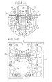
- Figs. 1(A) and 1(B) show a cylinder block in which a water passage forming member according to a first embodiment of the present invention is embedded by a casting process;
- Fig. 1(A) is a vertical sectional view of a principal portion of a cylinder block having the water passage forming member embedded therein by the casting process;
- Fig. 1(B) is a partial plan view of the cylinder block;
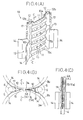
- Figs. 2(A), 2(B) and 2(C) show the water passage forming member according to the first embodiment of the present invention;
- Fig. 2(A) is a perspective view of the water passage forming member;
- Fig. 2(B) is a vertical sectional view taken along the B - B directed line in Fig. 2(A);
- Fig. 2(C) is a horizontal sectional plan view taken along the C - C directed line in Fig. 2(A);
- Fig. 3 is a vertical sectional view of a principal portion of a vertical multi-cylinder engine in which the water passage forming member according to the first embodiment is embedded by the casting process.
- Figs. 4(A), 4(B) and 4(C) show a water passage forming member according to a second embodiment of the present invention;
- Fig. 4(A) is a perspective view of the water passage forming member;
- Fig. 4(B) is a plan view showing a sectional right half portion of the water passage forming member;
- Fig. 4(C) is a vertical sectional view taken along the C - C directed line in Figs. 4(A) and 4(B);
- Figs. 5(A) and 5(B) show a principal portion of a cylinder block in which the water passage forming member according to the second embodiment is embedded by the casting process;
- Fig. 5(A) is a partial vertical sectional view of the cylinder block;
- Fig. 5(B) is a partial plan view of the cylinder block;
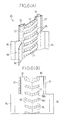
- Figs. 6(A) and 6(B) show a water passage forming member according to a third embodiment of the present invention;
- Fig. 6(A) is a perspective view of the water passage forming member;
- Fig. 6(B) is a vertical sectional front view of the water passage forming member;
- Figs. 7(A) and 7(B) show a water passage forming member according to a fourth embodiment of the present invention;
- Fig. 7(A) is a perspective view of the water passage forming member;
- Fig. 7(B) is a front view of the water passage forming member;
- Figs. 8(A) and 8(B) as well as Figs. 9(A) and 9(B) are front views showing variants of the water passage forming member according to the fourth embodiment of the present invention;
- Fig. 8(A) shows a first variant of the water passage forming member;
- Fig. 8(B) shows a second variant of the water passage forming member;
- Fig. 9(A) shows a third variant of the water passage forming member;
- Fig. 9(B) shows a fourth variant of the water passage forming member;
- Figs. 10(A), 10(B) and 10(C) show a first conventional example;
- Fig. 10(A) is a vertical sectional view of a principal portion of a multi-cylinder of a vertical engine;
- Fig. 10(B) is a horizontal sectional plan view taken along the B - B directed line in Fig. 10(A);
- Fig. 10(C) is a perspective view of a water passage forming member;
- Figs. 11(A), 11(B) and 11(C) show a second conventional example;
- Fig. 11(A) is a vertical sectional view of a principal portion of a multi-cylinder of a vertical engine;
- Fig. 11(B) is a horizontal sectional plan view taken along the B - B directed line in Fig. 11(A);
- Fig. 11(C) is a perspective view of a water passage forming member;
- Figs. 12(A), 12(B) and 12(C) show a third conventional example;
- Fig. 12(A) is a vertical sectional view of a principal portion of a multi-cylinder of a vertical engine;
- Fig. 12(B) is a horizontal sectional plan view taken along the B - B directed line in Fig. 12(A); and
- Fig. 12(C) is a perspective view of a water passage forming member.
-
- A first embodiment of the present invention will be explained hereinafter with reference to the attached drawings.
- Fig. 3 is a vertical sectional view of a principal portion of a vertical multi-cylinder engine having a water passage forming member according to the first embodiment of the present invention embedded therein by a casting process.
- As shown in Fig. 3, a vertical multi-cylinder engine E has a
cylinder head 20 fixedly secured byhead bolts 6 onto acylinder block 1 integrally formed with a crankcase,cylinder jackets 8 formed in thecylinder block 1 and ahead jacket 22 formed in thecylinder head 20 being brought into communication with each other through manyjacket communication ports 24 formed in portions except aconnection wall 4 to cool thecylinder head 20 by the cooling water which has already cooled thecylinder block 1. - As shown in Figs. 1(A) and 1(B) as well as in Fig. 3, a cylinder cooling apparatus of a multi-cylinder engine according to the present invention has a multi-cylinder 2 constructed by arranging a plurality of
cylinders 3 in thecylinder block 1 side by side in a front and rear direction and connecting theadjacent cylinders connection wall 4, and also it has thecylinder jackets 8 formed so as to surround themulti-cylinder 2. The waterpassage forming member 10 to be explained later is embedded in theconnection wall 4 by the casting process. - Now, characteristic constructions of the first embodiment will be explained hereinafter.
- As shown in Figs. 2(A), 2(B) and 2(C), the water
passage forming member 10 is constructed by superposing two press-formedsheet metal bodies sheet metal bodies - The water
passage forming member 10 is provided with a pair of left and right verticaljacket communication passages cylinder jackets cylinder block 1 into communication with ahead jacket 22, coolingwater passages 15 arranged vertically and in multiple stage for bringing the paired left and rightjacket communication passages non-hollow portions 11 arranged in multiple stage and alternately with the coolingwater passages 15. The lower portions of the paired left and rightjacket communication passages water induction portions respective cylinder jackets water induction portions water passages 15 and flow out into thehead jacket 22 disposed above thehead side portion 4a through thejacket communication passages - When the
non-hollow portions 11 and the coolingwater passages 15 are formed vertically and in multiple stage as well as arranged alternately with each other as disclosed in the above-mentioned embodiment, thenon-hollow portions 11 serve as ribs for mechanically reinforcing theconnection wall 4 and provide such an advantage that they can effectively cope with a pressurizing force acting on theconnection wall 4 during the machining of cylinder bores or the engine operation in comparison with the case where the coolingwater passage 15 is formed longitudinally elongated and flat in the vertical sectional side view like that in the first conventional example. - That is, the plural
cooling water passages 15 formed vertically and in multiple stage as well as alternately with thenon-hollow portions 11 increase the mechanical strength remarkably in comparison with the flat longitudinally elongated coolingwater passage 115 of the conventional example. Thereby, it is not apprehended that local distortions are produced during the boring of thecylinder bore 3a. - Since the multi-stage and
non-hollow portion 11 reinforces theconnection wall 4 mechanically, the waterpassage forming member 10 can be thinned to the utmost and as a result theconnection wall 4 can be thinned to the utmost. Thereby, the distance between the cylinder bores can be shortened by reducing the thickness of theconnection wall 4 more than that of the conventional example. Otherwise, the increasing of the stroke volume and as a result the increasing of the output power can be accomplished by enlarging a diameter of the cylinder bore. - A pair of left and right cylinder
head tightening bosses head side portion 4a to narrow intervals between thehead bolts cylinders 3 can be tightened more uniformly and strongly by that narrowed amount along the circumferential direction. Incidentally, though the present invention is not limited to this construction, when the pair of left and right cylinderhead tightening bosses head side portion 4a, advantageously it becomes possible to enlargejacket communication ports 23 formed in the upper end wall of thecylinder block 1 and bores of the pairedjacket communication passages - The paired
jacket communication passages bosses jacket communication ports 23 formed in the upper end wall of thecylinder block 1 as well as in the lower end wall of thecylinder head 20. As shown in Figs. 1(A) and 1(B), a lateral dimension d of the coolingwater passages 15 is set smaller than a lateral dimension D of theconnection wall 4. Thereby, the interval d between the inside edges of the openings of the pairedjacket communication passages connection wall 4. Accordingly, since the interval between the paired left andright head bolts jacket communication passages head bolts 6 arranged around thecylinder 3, it becomes possible to tighten thecylinders 3 more uniformly and strongly along the circumferential direction thereof. Thereby, it becomes possible to increase the gas sealing pressure. - The paired left and right cooling
water induction portions water guide plates circumferential surfaces rear cylinders water induction portions water passages 15 and thejacket communication passages 12 from the coolingwater induction portions cylinder jackets head jacket 22 disposed above theconnection wall 4, through thejacket communication passages water passages 15 in the upper half portion and thejacket communication passages head side portion 4a intensively. Thereby, the increasing of the engine stroke volume and as a result the increasing of the output power can be accomplished. - That is, since the piston ring can be cooled intensively through the cylinder wall by cooling the
head side portion 4a intensively, it becomes possible to relocate the top ring nearer to the piston top surface as much as possible and to reduce the annular dead space as much as possible which exists around the external circumference of the piston top portion and which doesn't contribute to the combustion, thereby improving the air utilizing ratio. Thus, along with this, it becomes possible to preclude the seizing of the top ring which might be caused by an unburnt portion of the fuel and carbonization of the lubrication oil. - Further, along with the relocation of the top ring nearer to the piston top surface as much as possible, the position of the piston pin can be relocated nearer to the piston top surface as much as possible to enlarge a rotation radius of a crank shaft correspondingly by that neared length. Therefore, it becomes possible to accomplish the relative downsizing of the connecting rod engine without modifying the engine physique and the increasing of the engine output power by enlarging the piston stroke. Since the
head side portion 4a can be cooled intensively, it becomes also possible to accomplish the increasing of the stroke volume by enlarging the diameter of the cylinder bore. Further, when the present invention is also applied to a multi-cylinder engine or the like equipped with a turbocharger, it becomes possible to accomplish the relative downsizing and the increasing of the engine output power. - Figs. 4(A), 4(B) and 4(C) show a water passage forming member according to the second embodiment of the present invention, and Figs. 5(A) and 5(B) show the principal portion of the cylinder block in which the water passage forming member is embedded by the casting process.
- As illustrated in the drawings, similarly to the first embodiment, the water
passage forming member 10 is formed into an integral construction by superposing twosheet metal bodies non-hollow portions joint portions jacket communication passages - In this embodiment, though the
non-hollow portions 11 and the coolingwater passages 15 are formed vertically and in multiple stage as well as alternately with each other, as shown in Figs. 4(A), 4(B) and 4(C), the coolingwater passages 15 havehollow portions 15a having wedge-like configurations in the plan view and formed symmetrically in a left and right direction so that their leading ends face the middles of thepassages 15. - That is, though the thickness of the
connection wall 4 is smallest at its mid portion and largest at its opposed end portions, when the coolingwater passages 15 are formed in the wedge-like configuration in the plan view corresponding to the thickness of theconnection wall 4 and symmetrically in the left and right direction so that their leading ends face the middles of thepassages 15, the waterpassage forming member 10 can be thinned to the utmost and as a result theconnection wall 4 can be thinned to the utmost. Thereby, the distance between the cylinder bores can be shortened by reducing the thickness of theconnection wall 4 more than those of the conventional examples. Otherwise, the increasing of the stroke volume and as a result the increasing of the output power can be accomplished by enlarging the diameter of the cylinder bore. - As shown in Fig. 4(A), the paired left and right cooling
water passages 15 are formed acclivously outward at theirupper edges 15b in the left and right directions. That is, even when steam is generated by the boiling of the cooling water within the respectivecooling water passages 15, the steam moves upward along the acclivousupper edges 15b of the respectivecooling water passages 15 to escape into thehead jacket 22 through thejacket communication passages 12. Thereby, the cooling performance can be maintained at a high level. - One of outer edge
joint portions 17 formed at the outer edges of thejacket communication passages cylinders 3 between the onecylinder 3 and the one cylinderhead tightening boss 5, and the other outer edgejoint portions 17 is embedded by the casting process eccentrically at a position near to theother cylinder 3 between theother cylinder 3 and the other cylinderhead tightening boss 5. That is, since an interval between the left and right cylinderhead tightening bolts joint portions 17 are superposed one on another on the outsides of the left and rightjacket communication passages jacket communication passage 12 becomes small. Thereupon, as mentioned above, when the outer edgejoint portions cylinders jacket communication passage 12. - As shown in Fig. 4(B), the paired
jacket communication passages bosses jacket communication ports 23 formed in the upper end wall of thecylinder block 1 and in the lower end wall of thecylinder head 20. As shown in Fig. 4(A), the upper end portion of thejacket communication passage 12 is slightly higher than thenon-hollow portion 11 at the upper edge thereof. This attempts to makesand cores 12b for use in forming thejacket communication ports 23 hardly break by setting thejacket communication ports 23 formed in the upper end wall of thecylinder block 1 relatively shorter. - The
symbol 16 in Fig. 4(A) designates a fore and rear wall connecting port of theconnection wall 4. Thenon-hollow portion 11 of the present invention is not limited to one having the fore and rearwall connecting ports 16. But, when the fore and rearwall connecting ports 16 are provided, there appears an advantage that theconnection wall 4 can more strongly cope with a pressurizing force acting thereon during the machining of the cylinder bore or the engine operation. Configurations of the fore and rearwall connecting port 16 will be explained later. - Figs. 6(A) and 6(B) show a water passage forming member according to the third embodiment of the present invention, Fig. 6(A) is a perspective view of the water passage forming member and Fig. 6(B) is a vertical sectional front view of the water passage forming member.
- In this embodiment, as illustrated in the drawings, while the
non-hollow portions 11 are formed like the V-letter, upper andlower edges cooling water passages 15 are acclivous outward in the left and right directions. The other constructions thereof are the same as those of the second embodiment (Fig. 4(A)). That is, even when steam is generated by the boiling of the cooling water within the respectivecooling water passages 15, the steam moves upward along the acclivousupper edges 15b of the respectivecooling water passages 15 to escape into thehead jacket 22 through thejacket communication passages 12. Incidentally, since it is enough to form at least theupper edge 15b of each of the paired left and right coolingwater passages 15 acclivously outward in the left and right directions, it is optional whether thelower edge 15c of each of the coolingwater passages 15 is formed acclivously outward in the left and right directions or not. - Figs. 7(A) and 7(B) show a water passage forming member according to the fourth embodiment of the present invention. Fig. 7(A) is a perspective view of the water passage forming member and Fig. 7(B) is a front view of the water passage forming member.
- In this embodiment, as illustrated in the drawings, the water
passage forming member 10 is constructed as an integral unit by superposing twosheet metal bodies joint portions jacket communication passages joint portions sheet metal bodies - Further, in this embodiment, as illustrated in the drawings, fore and rear
wall connecting ports 16 for connecting the fore and rear wall portions of theconnection wall 4 to each other are opened in respectivenon-hollow portions 11, and the other constructions are the same as those in the second embodiment (Fig. 4(A)). - That is, since the
non-hollow portions 11 have the fore and rearwall connecting ports 16 each formed like an elongated port, it becomes possible to more strongly cope with the pressurizing force acting on theconnection wall 4 during the machining of the cylinder bore or the engine operation. - The
non-hollow portions 11 formed vertically and in multiple stage serve as ribs for mechanically reinforcing theconnection wall 4, so that coolingwater passages 15 formed vertically and in multiple stage as well as alternately with thosenon-hollow portions 11 can be improved remarkably in the mechanical strength when compared with the flat and vertically elongated coolingwater passages 15 of the conventional examples. Thereby, it is not apprehended that local distortions are produced during the boring of thecylinder bore 3a. - Moreover, since
upper edges 15b of the coolingwater passages 15 are formed acclivously outward in the left and right directions, the cooling performance can be maintained at a high level. That is, even when steam is generated by the boiling of the cooling water within the respectivecooling water passages 15, the steam moves upward along the acclivousupper edges 15b of the respectivecooling water passages 15 and escapes into thehead jacket 22 through thejacket communication passages 12. Thereby, the cooling performance can be maintained at a high level. - Figs. 8(A) and 8(B) as well as Figs. 9(A) and 9(B) are front views showing variants of the water passage forming member according to the fourth embodiment. Fig. 8(A) shows a first variant of the water passage forming member. Fig. 8(B) shows a second variant of the water passage forming member. Fig. 9(A) shows a third variant of the water passage forming member, and Fig. 9(B) shows a fourth variant of the water passage forming member.
- As shown in Fig. 8(A), the first variant is constructed by integrally securing the vertical outer edge
joint portions jacket communication passages non-hollow portions 11 to each other by means of seam welding respectively. The other constructions are the same as those in Fig. 7(A). - As shown in Fig. 8(B), the second variant is constructed by integrally securing the vertical outer edge
joint portions jacket communication passages non-hollow portions non-hollow portions wall connecting ports 16 formed in the respectivenon-hollow portions 11 are formed by opening a plurality of round ports at certain intervals, and the other constructions are the same as those in Fig. 7(A). Since thenon-hollow portions non-hollow portions - That is, when the water
passage forming member 10 is embedded in thehead side portion 4a of theconnection wall 4 by the casting process, the foundry sand is previously stuffed into thejacket communication passages 12 and thehollow portions 15 of the waterpassage forming member 10 under a pressure of the highly pressurized air. But, when thenon-hollow portions non-hollow portions passage forming member 10 becomes larger. This problem can be solved by integrally securing thenon-hollow portions passage forming member 10 can be maintained. - As shown in Fig. 9(A), in the third variant, the
non-hollow portions 11 formed vertically and in multiple stage are connected to verticalnon-hollow portions 11b at the middle portions thereof. The fore and rearwall connecting ports 16 are formed as elongated ports in the respectivenon-hollow portions 11, and the other constructions are the same as those in Fig. 7(A). Incidentally, the paired left and right wedge-likecooling water passages 15 are partitioned by the verticalnon-hollow portions 11b so as to be formed like bags each of which is shut off at the middle. Thereupon, a great deal of the cooling water flows into the paired left and right bag-likecooling water passages 15 and the left and rightjacket communication passages 12 from the coolingwater induction portions head jacket 22 disposed above theconnection wall 4, through thejacket communication passages - As shown in Fig. 9(B), in the fourth variant, the vertical outer edge
joint portions jacket communication passages non-hollow portions 11. A single round port is formed as the fore and rearwall connecting port 16 in each of thenon-hollow portions 11, and the other constructions are the same as those in Fig. 7(A). - The present invention is not limited to the above-mentioned embodiments and can be embodied in various ways by optional combination with the following components (a) to (j).
- a) Cooling
water passages 15 each formed like a bag by the shutoff at the middle. - b) Paired left and right cooling
water induction portions jacket communication passages respective cooling jackets - c) Fore and rear
wall connecting ports 16 formed in thenon-hollow portions 11 formed vertically and in multiple stage. - d) Cooling
water passages 15 constructed by arranging thehollow portions 15a having wedge-like configurations in the plan view with their leading ends facing the middles, symmetrically in the left and right direction. - e) Cooling
water passages 15 with theirupper edges 15b formed acclivously outward in the left and right directions. - f) The paired left and right cylinder
head tightening bosses side portion 4a of theconnection wall 4, and thejacket communication passages head tightening bosses - g) Water
passage forming member 10 integrally moulded by means of, for example precision casting, in place of the waterpassage forming member 10 constructed by integrally securing the twosheet metal bodies 10a to each other while opposing each other. - h) The
non-hollow portions sheet metal bodies joint portions jacket communication passages - i) The interval d between the inside edges of the openings of
the paired
jacket communication passages connection wall 4 in the left and right direction. - j) One of the outer edge
joint portions 17 is embedded by the casting process so as to be disposed eccentrically nearer to onecylinder 3 between the onecylinder 3 and the one cylinderhead tightening boss 5, and the other thereof is embedded by the casting process so as to be disposed eccentrically nearer to theother cylinder 3 between theother cylinder 3 and the other cylinderhead tightening boss 5. -
Claims (6)
- A cylinder cooling apparatus of a multi-cylinder engine having a water passage forming member (10) embedded in a connection wall (4) between adjacent bores (3a, 3a) of a multi-cylinder block (1) by a casting process, wherein the water passage forming member (10) is provided with vertical left and right jacket communication passages (12, 12) for communicating cylinder jackets (8, 8) within the multi-cylinder block (1) with a head jacket (22) and is provided with cooling water passages (15) extending horizontally between the left and right jacket communication passages (12, 12), said cooling water passages being hollow portions formed by side walls of the water passage forming member being spaced apart, interspaced by non-hollow portions formed by the side walls lying together, characterised in that:
the water passage forming member (10) has a plurality of non-hollow portions between its uppermost and lowermost parts, each of the non-hollow portions extending horizontally from one of the jacket communication passages (12, 12), to the other, there being a non-hollow portion both above and below each of the cooling water passages (15). - A cylinder cooling apparatus according to claim 1, characterised in that:
left and right opposed side portions of a head side portion (4a) of the connection wall (4) are formed integrally and continuously with cylinder head tightening bosses (5, 5) and the paired right and left jacket communication passages (12, 12) are positioned inside the tightening bosses (5, 5). - A cylinder cooling apparatus according to claim 1 or 2, characterised in that
each of the cooling water passages (15) has an upper edge (15b) formed acclivously outward in left and right directions. - A cylinder cooling apparatus according to claim 1 or 2, characterised in that
each of the non-hollow portions (11) of the water passage forming member (10) is provided with a fore-and-rear wall connecting port (16) of the connection wall (4). - A cylinder cooling apparatus according to claim 1 or 2, characterised in that:
the water passage forming member (10) is provided with a pair of right and left cooling water induction portion (13, 13) opened toward the right and left cylinder jackets (8, 8) and disposed in lower portions of the paired right and left jacket communication passages (12, 12), and the cooling water induction portions (13, 13) are constructed by forward and rearward spreading apart of a pair of fore and rear cooling water guide plates (14, 14) respectively along a cyliner external circumferential surface (3b). - A cylinder cooling apparatus according to claim 1 or 2, characterised in that
each cooling water passage (15) comprises hollow portions (15a, 15a) being symmetrical in a right and left direction and having wedge-like configuration in plan view which are arranged with their leading ends facing a middle of the connection wall (4) in the right and left direction
Applications Claiming Priority (9)
| Application Number | Priority Date | Filing Date | Title |
|---|---|---|---|
| JP60818/95 | 1995-03-20 | ||
| JP6081895 | 1995-03-20 | ||
| JP6081895 | 1995-03-20 | ||
| JP7181215A JP3057414B2 (en) | 1995-07-18 | 1995-07-18 | Siamese cylinder cooling system |
| JP18121595 | 1995-07-18 | ||
| JP181215/95 | 1995-07-18 | ||
| JP210383/95 | 1995-08-18 | ||
| JP21038395 | 1995-08-18 | ||
| JP21038395 | 1995-08-18 |
Publications (3)
| Publication Number | Publication Date |
|---|---|
| EP0743442A2 EP0743442A2 (en) | 1996-11-20 |
| EP0743442A3 EP0743442A3 (en) | 1997-01-08 |
| EP0743442B1 true EP0743442B1 (en) | 2000-09-20 |
Family
ID=27297306
Family Applications (1)
| Application Number | Title | Priority Date | Filing Date |
|---|---|---|---|
| EP96103144A Expired - Lifetime EP0743442B1 (en) | 1995-03-20 | 1996-03-01 | Cylinder cooling apparatus of multi-cylinder engine |
Country Status (4)
| Country | Link |
|---|---|
| US (1) | US5669339A (en) |
| EP (1) | EP0743442B1 (en) |
| CN (1) | CN1085296C (en) |
| DE (1) | DE69610358T2 (en) |
Families Citing this family (15)
| Publication number | Priority date | Publication date | Assignee | Title |
|---|---|---|---|---|
| JP2001164985A (en) * | 1999-09-28 | 2001-06-19 | Kubota Corp | Cylinder block for multi-cylinder engine and casting method thereof |
| DE10235910B4 (en) * | 2002-08-06 | 2013-02-28 | Peak-Werkstoff Gmbh | Composite of cylinder liners made of light metal alloy, method for producing a composite and method for pouring a composite |
| US20050150476A1 (en) * | 2002-08-06 | 2005-07-14 | Uwe Gohrbandt | Combination of cylinder liners consisting of a light metal alloy |
| JP4227914B2 (en) | 2004-03-10 | 2009-02-18 | トヨタ自動車株式会社 | Cylinder block cooling structure |
| JP4279714B2 (en) * | 2004-03-31 | 2009-06-17 | トヨタ自動車株式会社 | Cylinder block cooling structure |
| JP4279713B2 (en) | 2004-03-31 | 2009-06-17 | トヨタ自動車株式会社 | Cylinder block cooling structure |
| DE102005048650B4 (en) * | 2005-10-11 | 2007-09-13 | Daimlerchrysler Ag | Manufacturing process and design for cast components with cavities |
| US8689744B2 (en) * | 2008-08-04 | 2014-04-08 | Hyundai Motor Company | Cooling device and insert for water jacket of internal combustion engine |
| US8408178B2 (en) * | 2009-08-04 | 2013-04-02 | International Engine Intellectual Property Company, Llc | Engine crankcase firing deck having anti-distortion projections |
| WO2012129339A2 (en) | 2011-03-21 | 2012-09-27 | Cummins Intellectual Property, Inc. | Internal combustion engine having improved cooling arrangement |
| US8555950B2 (en) | 2011-10-25 | 2013-10-15 | Ford Global Technologies, Llc | Organic-like casting process for water jackets |
| DE102013113609B4 (en) * | 2013-12-06 | 2022-02-24 | Dr. Ing. H.C. F. Porsche Aktiengesellschaft | Crankcase with cooling water distribution for a multi-cylinder internal combustion engine |
| DE102016102159A1 (en) * | 2016-02-08 | 2017-08-10 | Dr. Ing. H.C. F. Porsche Aktiengesellschaft | Throttling element for an engine block of an internal combustion engine, engine block for an internal combustion engine, method for producing an engine block for an internal combustion engine and internal combustion engine |
| DE102017206716B4 (en) * | 2017-04-21 | 2021-05-06 | Ford Global Technologies, Llc | Cylinder block of an internal combustion engine |
| CN108425761B (en) * | 2018-04-03 | 2024-09-17 | 林上煜 | Cylinder body structure of automobile engine |
Family Cites Families (10)
| Publication number | Priority date | Publication date | Assignee | Title |
|---|---|---|---|---|
| DE1955140A1 (en) * | 1969-11-03 | 1971-05-27 | Maschf Augsburg Nuernberg Ag | Fluid-cooled cylinder liner for internal combustion engines |
| JPS5642744A (en) * | 1979-09-14 | 1981-04-21 | Yamaha Motor Co Ltd | Low vibration engine |
| JPS57198338U (en) * | 1981-06-11 | 1982-12-16 | ||
| JPS597242A (en) * | 1982-07-06 | 1984-01-14 | Daido Steel Co Ltd | Method and device for inspecting fitting of screw thread |
| JPS5968155A (en) * | 1982-10-08 | 1984-04-18 | Matsushita Electric Ind Co Ltd | half plate cathode ray tube |
| JPS59107946A (en) * | 1982-12-07 | 1984-06-22 | 住友金属工業株式会社 | Lime baking device |
| JPH077383B2 (en) * | 1986-01-27 | 1995-01-30 | 日本電気株式会社 | Waiting circuit |
| DE3629672A1 (en) * | 1986-09-01 | 1988-03-10 | Kloeckner Humboldt Deutz Ag | INTERNAL COMBUSTION ENGINE WITH LIQUID-COOLED CYLINDER BUSHING |
| JPS63253156A (en) * | 1987-04-08 | 1988-10-20 | Daihatsu Motor Co Ltd | Cooling device for siamese type cylinder block |
| US5188071A (en) * | 1992-01-27 | 1993-02-23 | Hyundai Motor Company | Cylinder block structure |
-
1996
- 1996-02-28 US US08/608,076 patent/US5669339A/en not_active Expired - Lifetime
- 1996-03-01 DE DE69610358T patent/DE69610358T2/en not_active Expired - Lifetime
- 1996-03-01 EP EP96103144A patent/EP0743442B1/en not_active Expired - Lifetime
- 1996-03-20 CN CN96104264A patent/CN1085296C/en not_active Expired - Fee Related
Also Published As
| Publication number | Publication date |
|---|---|
| DE69610358T2 (en) | 2001-04-26 |
| CN1140795A (en) | 1997-01-22 |
| DE69610358D1 (en) | 2000-10-26 |
| US5669339A (en) | 1997-09-23 |
| CN1085296C (en) | 2002-05-22 |
| EP0743442A2 (en) | 1996-11-20 |
| EP0743442A3 (en) | 1997-01-08 |
Similar Documents
| Publication | Publication Date | Title |
|---|---|---|
| US5669339A (en) | Cylinder cooling apparatus of multi-cylinder engine | |
| US8256389B2 (en) | Cylinder block | |
| US10550753B2 (en) | Cylinder block of an internal combustion engine | |
| JP3057421B2 (en) | Siamese cylinder cooling system | |
| US6735863B1 (en) | Method of engine cylinder bore enlargement | |
| US5809946A (en) | Structure of an open deck type cylinder block | |
| JP3120322B2 (en) | Siamese cylinder cooling system | |
| JPH0821299A (en) | Cylinder block of internal combustion engine | |
| JP2000130253A (en) | Siamese cylinder cooling system | |
| US4893597A (en) | Engine cylinder assembly having an intake cross-passageway | |
| JP3344980B2 (en) | Siamese cylinder cooling system | |
| JP3057414B2 (en) | Siamese cylinder cooling system | |
| JP3057419B2 (en) | Siamese cylinder cooling system | |
| JP3656060B2 (en) | Siamese cylinder cooling system | |
| JPH09177599A (en) | Siamese cylinder cooling device | |
| JP2839826B2 (en) | Structure of Siamese type cylinder block | |
| US5271363A (en) | Reinforced cylinder for an internal combustion engine | |
| JPH0326288Y2 (en) | ||
| US6886504B2 (en) | Engine of reciprocating piston type | |
| JP3108903B2 (en) | Piston engine | |
| JPH01273663A (en) | Manufacturing method of cylinder with scavenging passage for two-stroke engine | |
| JPH08218936A (en) | Scavenging chamber structure of two-cycle engine | |
| JPS59126051A (en) | Cylinder head | |
| KR100496057B1 (en) | Cooling system of multi cylinder cylinder | |
| JPS5924846Y2 (en) | cylinder block of internal combustion engine |
Legal Events
| Date | Code | Title | Description |
|---|---|---|---|
| PUAI | Public reference made under article 153(3) epc to a published international application that has entered the european phase |
Free format text: ORIGINAL CODE: 0009012 |
|
| AK | Designated contracting states |
Kind code of ref document: A2 Designated state(s): DE FR GB IT |
|
| PUAL | Search report despatched |
Free format text: ORIGINAL CODE: 0009013 |
|
| AK | Designated contracting states |
Kind code of ref document: A3 Designated state(s): DE FR GB IT |
|
| 17P | Request for examination filed |
Effective date: 19970401 |
|
| 17Q | First examination report despatched |
Effective date: 19990323 |
|
| GRAG | Despatch of communication of intention to grant |
Free format text: ORIGINAL CODE: EPIDOS AGRA |
|
| GRAG | Despatch of communication of intention to grant |
Free format text: ORIGINAL CODE: EPIDOS AGRA |
|
| GRAH | Despatch of communication of intention to grant a patent |
Free format text: ORIGINAL CODE: EPIDOS IGRA |
|
| GRAH | Despatch of communication of intention to grant a patent |
Free format text: ORIGINAL CODE: EPIDOS IGRA |
|
| GRAH | Despatch of communication of intention to grant a patent |
Free format text: ORIGINAL CODE: EPIDOS IGRA |
|
| GRAA | (expected) grant |
Free format text: ORIGINAL CODE: 0009210 |
|
| AK | Designated contracting states |
Kind code of ref document: B1 Designated state(s): DE FR GB IT |
|
| REF | Corresponds to: |
Ref document number: 69610358 Country of ref document: DE Date of ref document: 20001026 |
|
| ITF | It: translation for a ep patent filed | ||
| ET | Fr: translation filed | ||
| PLBE | No opposition filed within time limit |
Free format text: ORIGINAL CODE: 0009261 |
|
| STAA | Information on the status of an ep patent application or granted ep patent |
Free format text: STATUS: NO OPPOSITION FILED WITHIN TIME LIMIT |
|
| 26N | No opposition filed | ||
| REG | Reference to a national code |
Ref country code: GB Ref legal event code: IF02 |
|
| REG | Reference to a national code |
Ref country code: DE Ref legal event code: R082 Ref document number: 69610358 Country of ref document: DE Representative=s name: KAHLER, KAECK & MOLLEKOPF, DE |
|
| REG | Reference to a national code |
Ref country code: DE Ref legal event code: R082 Ref document number: 69610358 Country of ref document: DE Representative=s name: KAHLER, KAECK & MOLLEKOPF, DE |
|
| PGFP | Annual fee paid to national office [announced via postgrant information from national office to epo] |
Ref country code: IT Payment date: 20140307 Year of fee payment: 19 Ref country code: FR Payment date: 20140311 Year of fee payment: 19 |
|
| PGFP | Annual fee paid to national office [announced via postgrant information from national office to epo] |
Ref country code: GB Payment date: 20140226 Year of fee payment: 19 |
|
| PGFP | Annual fee paid to national office [announced via postgrant information from national office to epo] |
Ref country code: DE Payment date: 20140417 Year of fee payment: 19 |
|
| REG | Reference to a national code |
Ref country code: DE Ref legal event code: R119 Ref document number: 69610358 Country of ref document: DE |
|
| GBPC | Gb: european patent ceased through non-payment of renewal fee |
Effective date: 20150301 |
|
| PG25 | Lapsed in a contracting state [announced via postgrant information from national office to epo] |
Ref country code: IT Free format text: LAPSE BECAUSE OF NON-PAYMENT OF DUE FEES Effective date: 20150301 |
|
| REG | Reference to a national code |
Ref country code: FR Ref legal event code: ST Effective date: 20151130 |
|
| PG25 | Lapsed in a contracting state [announced via postgrant information from national office to epo] |
Ref country code: DE Free format text: LAPSE BECAUSE OF NON-PAYMENT OF DUE FEES Effective date: 20151001 Ref country code: GB Free format text: LAPSE BECAUSE OF NON-PAYMENT OF DUE FEES Effective date: 20150301 |
|
| PG25 | Lapsed in a contracting state [announced via postgrant information from national office to epo] |
Ref country code: FR Free format text: LAPSE BECAUSE OF NON-PAYMENT OF DUE FEES Effective date: 20150331 |