EP0742345A2 - Verfahren und Vorrichtung zum Gewinnen eines Bodenschatzes aus einer Lagerstätte - Google Patents
Verfahren und Vorrichtung zum Gewinnen eines Bodenschatzes aus einer Lagerstätte Download PDFInfo
- Publication number
- EP0742345A2 EP0742345A2 EP96303200A EP96303200A EP0742345A2 EP 0742345 A2 EP0742345 A2 EP 0742345A2 EP 96303200 A EP96303200 A EP 96303200A EP 96303200 A EP96303200 A EP 96303200A EP 0742345 A2 EP0742345 A2 EP 0742345A2
- Authority
- EP
- European Patent Office
- Prior art keywords
- auger
- hole
- coal
- seam
- minable
- Prior art date
- Legal status (The legal status is an assumption and is not a legal conclusion. Google has not performed a legal analysis and makes no representation as to the accuracy of the status listed.)
- Granted
Links
- 238000000034 method Methods 0.000 title claims abstract description 36
- 239000003245 coal Substances 0.000 claims abstract description 138
- 238000011084 recovery Methods 0.000 claims abstract description 94
- XLYOFNOQVPJJNP-UHFFFAOYSA-N water Substances O XLYOFNOQVPJJNP-UHFFFAOYSA-N 0.000 claims abstract description 66
- 238000002347 injection Methods 0.000 claims abstract description 53
- 239000007924 injection Substances 0.000 claims abstract description 53
- 239000002360 explosive Substances 0.000 claims abstract description 24
- 238000005553 drilling Methods 0.000 claims abstract description 17
- 239000000463 material Substances 0.000 claims description 20
- 238000005065 mining Methods 0.000 description 23
- 239000002002 slurry Substances 0.000 description 18
- 239000012530 fluid Substances 0.000 description 15
- 239000011800 void material Substances 0.000 description 13
- 229910000831 Steel Inorganic materials 0.000 description 9
- 239000010959 steel Substances 0.000 description 9
- 238000005474 detonation Methods 0.000 description 7
- 241000196324 Embryophyta Species 0.000 description 5
- 239000012634 fragment Substances 0.000 description 4
- 230000003014 reinforcing effect Effects 0.000 description 4
- 238000005406 washing Methods 0.000 description 4
- 235000019738 Limestone Nutrition 0.000 description 3
- 239000003638 chemical reducing agent Substances 0.000 description 3
- 239000003250 coal slurry Substances 0.000 description 3
- 239000006028 limestone Substances 0.000 description 3
- 230000008569 process Effects 0.000 description 3
- 239000011435 rock Substances 0.000 description 3
- 230000009471 action Effects 0.000 description 2
- 238000010586 diagram Methods 0.000 description 2
- 238000009826 distribution Methods 0.000 description 2
- 230000005484 gravity Effects 0.000 description 2
- 230000002787 reinforcement Effects 0.000 description 2
- 238000003466 welding Methods 0.000 description 2
- 241000601170 Clematis lasiantha Species 0.000 description 1
- 206010042618 Surgical procedure repeated Diseases 0.000 description 1
- 238000004873 anchoring Methods 0.000 description 1
- 238000005422 blasting Methods 0.000 description 1
- 239000004568 cement Substances 0.000 description 1
- 238000003776 cleavage reaction Methods 0.000 description 1
- 230000009514 concussion Effects 0.000 description 1
- 238000010276 construction Methods 0.000 description 1
- 238000011109 contamination Methods 0.000 description 1
- 230000008878 coupling Effects 0.000 description 1
- 238000010168 coupling process Methods 0.000 description 1
- 238000005859 coupling reaction Methods 0.000 description 1
- 230000006378 damage Effects 0.000 description 1
- 230000003111 delayed effect Effects 0.000 description 1
- 230000001419 dependent effect Effects 0.000 description 1
- 230000000694 effects Effects 0.000 description 1
- 230000002708 enhancing effect Effects 0.000 description 1
- 230000007613 environmental effect Effects 0.000 description 1
- 238000004880 explosion Methods 0.000 description 1
- 238000007667 floating Methods 0.000 description 1
- 239000007789 gas Substances 0.000 description 1
- 239000003673 groundwater Substances 0.000 description 1
- 230000004048 modification Effects 0.000 description 1
- 238000012986 modification Methods 0.000 description 1
- 230000002093 peripheral effect Effects 0.000 description 1
- 238000007665 sagging Methods 0.000 description 1
- 239000004576 sand Substances 0.000 description 1
- 230000007017 scission Effects 0.000 description 1
- 239000007787 solid Substances 0.000 description 1
- 230000003068 static effect Effects 0.000 description 1
- 238000003860 storage Methods 0.000 description 1
- 239000002352 surface water Substances 0.000 description 1
- 239000002699 waste material Substances 0.000 description 1
- 239000002351 wastewater Substances 0.000 description 1
Images


Classifications
-
- E—FIXED CONSTRUCTIONS
- E21—EARTH OR ROCK DRILLING; MINING
- E21C—MINING OR QUARRYING
- E21C41/00—Methods of underground or surface mining; Layouts therefor
- E21C41/16—Methods of underground mining; Layouts therefor
-
- E—FIXED CONSTRUCTIONS
- E21—EARTH OR ROCK DRILLING; MINING
- E21B—EARTH OR ROCK DRILLING; OBTAINING OIL, GAS, WATER, SOLUBLE OR MELTABLE MATERIALS OR A SLURRY OF MINERALS FROM WELLS
- E21B43/00—Methods or apparatus for obtaining oil, gas, water, soluble or meltable materials or a slurry of minerals from wells
- E21B43/25—Methods for stimulating production
- E21B43/26—Methods for stimulating production by forming crevices or fractures
- E21B43/263—Methods for stimulating production by forming crevices or fractures using explosives
-
- E—FIXED CONSTRUCTIONS
- E21—EARTH OR ROCK DRILLING; MINING
- E21B—EARTH OR ROCK DRILLING; OBTAINING OIL, GAS, WATER, SOLUBLE OR MELTABLE MATERIALS OR A SLURRY OF MINERALS FROM WELLS
- E21B43/00—Methods or apparatus for obtaining oil, gas, water, soluble or meltable materials or a slurry of minerals from wells
- E21B43/29—Obtaining a slurry of minerals, e.g. by using nozzles
-
- E—FIXED CONSTRUCTIONS
- E21—EARTH OR ROCK DRILLING; MINING
- E21C—MINING OR QUARRYING
- E21C37/00—Other methods or devices for dislodging with or without loading
- E21C37/06—Other methods or devices for dislodging with or without loading by making use of hydraulic or pneumatic pressure in a borehole
- E21C37/12—Other methods or devices for dislodging with or without loading by making use of hydraulic or pneumatic pressure in a borehole by injecting into the borehole a liquid, either initially at high pressure or subsequently subjected to high pressure, e.g. by pulses, by explosive cartridges acting on the liquid
Definitions
- This invention relates to a method of removing minable products, such as coal, from an underground seam, and more particularly improvements in said method and tools used with said method.
- the mining method of this disclosure is classified by hydraulic engineers as a "closed flow hydraulic system.”
- the method employs the principles of mechanical and fluid dynamics in a closed conduit system under pressure and vacuum.
- the original invention is described in U.S. Patent 5,139,312 granted to the inventor.
- the present invention describes a method that improves upon the prior invention and utilized less costly tools in recovery of minable ore, thus enhancing cost efficiency.
- the mining process begins after having selected a proven geologic prospect worthy of mining such as a coal seam.
- the prospect should be such as to have a thick coal seam (18 inches or more) that uniformly slopes from 1° to 90° degrees.
- There should be a readily available water supply such as deep wells, lakes or large ponds, water filled old open strip pits or underground mines, rivers or permanent streams.
- the on-site location requires a minimum of surface disturbance usually a few acres. There is no requirement for settlement ponds or for disposal of waste fluids or slurry.
- the first step is the drilling of a 22 inch borehole on the down dip end of the coal seam.
- the method herein discussed assumes the hole to be about 100 feet deep, however, this method may be applicable to much greater depths.
- the coal seam discussed herein is assumed to range from 28 to 36 inches thick but, once again, this range is only assumed for convenience.
- Other 22 inch drill holes will be spaced approximately 660 to 1320 feet apart in a line paralleling the strike of the underlying coal seam. These large diameter boreholes are used for recovery of coal and slurry fluids at the surface from underground coal beds, and are termed "recovery holes.”
- injection holes A series of secondary 6 inch boreholes are termed "injection holes.”
- the number of injection holes used in a mining unit with one recovery hole will depend on the geology, coal type, coal dip and thickness, mining depth, equipment size and other site specific factors.
- the equipment inserted into the recovery borehole includes a tubular collared and jointed shaft and a downhole recovery tool.
- the downhole recovery tool consists of a bottom hole auger device that is placed into the coal seam, extending about 12 inches below the coal seam and 36 inches above the top of the coal seam. This bottom hole tool has a window cut the length of the coal bed thickness through which the coal seam is exposed to the inside auger tool.
- a discharge head tool providing a connection from the pipe in the hole to a dredge pump and a rotary power source on the surface. Between these two tools are placed a column of necessary lengths of tubular collared and joined hollow shaft for a closed pipe system with inside auguring capabilities.
- the recovery hole is first drilled about 20 feet deep into bedrock with a 22 inch bit.
- the twenty foot deep hole is then cemented to the bottom with 20 inch casing.
- the hole is then drilled deeper through the surface casing with a seventeen and one-half (17 1/2) inch bit to the coal and one foot below the coal seam.
- the bottom hole tool with the top portion being reduced to 12 inches, is lowered to the bottom of the hole by welding end-to-end longer joints of 12 inch (inside diameter) casing to make up a casing column.
- the downhole tool with auger device has a hollow tubular shaft to which are attached additional sections of tubular shafts all the way to the top of the hole.
- Water under pressure is pumped down the tubular shaft to exit out the water nozzles spaced vertically and radially outward along the shaft including the downhole tool.
- the rotation of the downhole tool auger, the pressurized water nozzles pointed upward and the dredge pump on the surface all work to lift the coal slurry up and out of the recovery hole.
- the initial stage of the drilling operation begins with four boreholes drilled in close proximity to the large diameter recovery hole, which was previously located and staked for drilling.
- the procedure of drilling commences with three 6 inch diameter injection boreholes, each spaced five feet apart from the recovery borehole.
- the 6 inch holes are drilled in a straight line updip and perpendicular to the strike of the underlying coal seam. Each hole is drilled to the bottom of the coal bed.
- the drilling and completion of the first two 6 inch boreholes are the same except only one is done at a time.
- the first borehole is drilled through the coal bed and surface casing is set. Underwater explosives are placed only into the coal seam with an electrical detonating cap and wire lead to the surface at the top of the coal bed.
- an inflatable five foot elongated balloon type hole plug Above the explosives in a hole is placed an inflatable five foot elongated balloon type hole plug. It may become necessary in some hole situations to add 3 feet of limestone stemming atop the explosives and then put the balloon plug in place.
- This balloon is attached to a small air hose extending to the surface where it can be inflated or deflated and retrieved when desirable. If the injection hole is wet and filled up to some static water level then the air balloon plug is inflated at that point rather than at the top of the explosives. This plugging device will temporarily seal the hole, thereby preventing any explosive energy from being directed up the drill hole during the detonation of the previously set explosive material in the coal seam.
- the large diameter recovery hole Prior to detonation of any of the explosives, the large diameter recovery hole is drilled through the coal seam and cleaned of all material by the drilling rig. Prior to detonation of the explosives in the hole nearest to the large recovery hole, the drilling bit is raised a few feet above the coal level, but remains in the recovery hole. The nearest 6 inch hole is then detonated. Since the path of least resistance is toward the only void in the coal, the recovery hole, the blasted material will be forced to this void. Subsequent to the blast, the drilling bit is re-lowered to the coal seam level and any blasted material is then removed by the drilling rig and the hole is recleaned.
- the second 6 inch injection borehole is then prepared like the first injection hole. Again, the recovery hole drilling rig bit is raised and the second hole is blasted. The recovery hole is recleaned subsequent to the blast. A third 6 inch injection hole is prepared and blasted in the same manner as the first two injection holes, and the recovery hole is again cleaned by the drilling rig. Casing is then set and cemented into the recovery hole. Bottom hole and surface equipment are set into place for hydraulic mining operations.
- the auguring operation is then started and water is pumped down the first 6 inch open hole.
- the pumped water forces the exploded coal down the coal seam to the recovery hole auger tool window.
- the second injection hole is pumped with water.
- the void area in the coal seam extends about 10 feet updip.
- the third injection hole is likewise water pressured from the surface, forcing the blasted chunks of coal to the recovery hole.
- the recovery hole is equipped with a pipe down the center axis of the hole all of the way down to the bottom hole tool.
- Water is forced down the hole which is forced out the nozzles spaced radially and vertically along the central pipe, and including the bottom hole tool.
- the pipe rotates, it rotates the special auger device in the bottom hole tool and it also rotates the water nozzles.
- the water nozzles are pointed upward so as to inject water under pressure up the recovery hole, which is intended to push the coal up the recovery hole from the coal seam.
- roller bearings Located radially outward from the nozzles are roller bearings which roll along the inside of the casing as the central pipe is rotated. The roller bearings aid in preventing the nozzles from impeding the rotation of the pipe and the auger in the bottom hole tool, and also aid in maintaining the pipe along the center axis of the recovery hole.
- injection holes #1 and #2 are fitted with 2 inch strands of pipe to the coal seam, where a sweep-jet nozzle is installed.
- These nozzles are short and vertically adjustable to accommodate the dip angle of the coal seam.
- the nozzle jet can be horizontally rotated from the surface.
- the pipe and nozzles are permanently lowered into the hole and into the void area in the coal seam.
- the pipe is sealed at the top of the surface casing with a screw cap with bearing for a water line.
- the water line pipe can be rotated through the bearing.
- the nozzle can be rotated toward the recovery hole.
- the two injection holes are each connected to a surface water pump.
- the third injection hole is hooked up to a third surface pump after removal of the inflatable balloon plug.
- the first and second injection holes are under continuous fluid flowage from the surface pumps. These pumps maintain a high water pressure to the nozzles to further pulverize the chunks of coal at the recovery hole and in the immediately mined area. These two injection holes also provide the necessary volume of water slurry to maintain the void area flow of slurry to the recovery hole.
- the recovery hole is also under continuous fluid flowage from a surface pump.
- the pump maintains a high water pressure to the nozzles which push the coal slurry out of the bottom hole tool up the recovery hole and out at the surface.
- the second stage of the operation is begun.
- This stage consists of drilling injection boreholes, loading them with explosives ready to be detonated in sequence for continuous operations.
- the 4th, 5th and all holes drilled thereafter, are drilled perpendicular to the coal strike and updip both in a straight line and radiating from the recovery hole.
- These holes are also drilled to the bottom of the coal seam, loaded with underwater explosives in the same manner as the first, second and third injection holes.
- These holes each contain a retrievable, inflatable five foot air balloon plugging device for plugging the hole at any ground water level in the hole. Explosives are then detonated by use of a cap and wire to the surface connected to an electrically controlled detonating device. If the holes are dry, it may be necessary to add a few feet of crushed limestone aggregates as stemming on top of the coal before setting the balloon plug. The need for the limestone stemming depends on the hardness of the strata on top and underlying the coal seam.
- bituminous coals are usually compact, brittle, banded and have a lamellar, conchoidal, splintery fractures and have more or less well defined prismatic jointing, they usually will disintegrate upon forces of explosives and high fluid pressure into cubical or prismatic blocks along their cleavage and joint planes.
- the coal from the detonated and pressured injection holes is forced to follow the path of least resistance, which is toward the bottom of the recovery hole where the coal enters the bottom hole tool through the window of the tool.
- the tool is designed to crush the coal into smaller sizes as the auger rotates.
- the coal due to its specific gravity, will free flow in the heavy medium slurry, up through the recovery assisted by the pressurized water nozzle pipe to the surface.
- the nozzle lift the fluid flow and prevents any blockage in the pipe.
- the dredge pump with its suction pulls the free flowing coal and material slurry from the hole through the discharge head tool, then forces the slurry onto the shaker and washing plant in a volume ratio of about 60% coal to 40% slurry fluids.
- Each injection hole is temporarily plugged following its detonation and coal removed. This is accomplished by use of an inflatable rubber device that will be placed in the hole between the surface and the top of the coal level, depending upon water levels in the hole, or just above the level where the coal seam was prior to coal removal in a dry hole situation. The device is then inflated and will remain in place until the hole is permanently sealed. This device will prevent underground fluids from exiting to the surface.
- the plugging of these holes is conducted by first removing the bottom hole auger tool and the pipe stem in the large recovery hole.
- the 12 inch casing in the recovery hole may also be removed.
- the recovery hole is filled with sand and gravel to within a few feet of the surface. If the casing is not removed then, the top three feet of casing is cut below ground level and the void is filled with cement.
- the 6 inch injection holes are then loaded with explosives at 10 to 20 feet above the original coal level. The exact level is determined by calculation dependent on the overburden material and coal seam void thickness. Upon detonation of the explosives in these holes, the blasted material collapses into the mining void below.
- the blasted material provides enough swell to completely fill the mine void and the blasted area with material, and prevents sagging of the overburden material at the ground surface. After blasting all boreholes, the air balloon type plugging devices and surface casing of each hole are removed and each hole is backfilled and cemented to within 2 feet of the surface.
- the auger tool used in this mining method consists of two separate devices used in conjunction with connecting pipe that is inserted into a vertical drill hole.
- This system provides an enclosed pipe passage from an underground coal bed to the surface.
- the device at the surface is termed a "discharge head tool”.
- the device installed underground and positioned through the coal bed interval is called the "bottom hole tool”.
- the bottom hole tool is typically the same 12 inch diameter cylinder as the casing pipe in the recovery hole that is constructed of 1/2 inch steel pipe.
- the length of the bottom hole tool cylinder varies by the thickness of the coal to be hydraulically mined. By way of example, assuming a specific coal seam thickness of 42 inches a window of this length is to be cut into the cylinder. This window is constructed by removal of up to 1/2 of the circumference wall.
- the window is placed in the coal between the top and bottom of the coal seam and exposes the inner-workings of the cylinder to the insitu coal.
- the window serves as a passage into the bottom hole tool cylinder for chunks of coal and water slurry which are under hydraulic pressure during operation of the device. In viewing the bottom hole tool in a vertical position, the window is cut into the middle and lower portions of the cylinder length.
- a one inch thick and 3 inch wide steel reinforcing strap is welded to the vertical outside edge of the window on the bottom hole tool.
- This reinforcement strap extends a few inches beyond the tool base for anchorage of the tool into the substrata. With this reinforcement strap affixed to the outside diameter of the bottom hole tool, it will typically have a total outside diameter of 14 inches.
- the bottom hole tool used in this mining method consists of a special augering device where the auger is not a continuous bar spiraling around the central shaft, but is rather made up of segments with openings in between. In this manner the auger segments wind around the central shaft for only 180° and appear to be on top of each other when viewed from above or along the vertical axis of the auger.
- this auger arrangement leaves a gap which allow the segmented auger blades to pass above and below a tooth like wedge mounted on a vertical bar called a "crushing bar".
- the crushing bar with spaced wedges is welded on the opposite side of the window on the inside of the bottom-hole tool.
- the crushing bar breaks up large chunks of coal in conjunction with the action of the auger and pushes the coal up the backside of the bottom-hole tool to the surface by the first lifting action of the bottom water nozzle.
- the deflection plate is a baffle welded to the inside of the casing. It is a circular steel plate angling downward from the window opening.
- the baffle is notched out to allow for rotation of the central shaft, through which pressurized water is pumped down to exit through the nozzles.
- the bottom water nozzle is located below the baffle plate and the baffle plate acts further to prevent the pressurized water from the lowest nozzle to be forced out into the coal seam through the window area.
- a pipe section that houses a bearing and bottom end assembly for holding the lower end of the auguring device.
- a special segment at the top of the bottom hole tool adjusting the outside diameter from 20 to 12 inches in diameter so additional sections of 12 inch pipe casing can be joined to the bottom hole tool for connection of it to the surface discharge head tool.
- the top of the auger is connected by a shaft to a rotary power source.
- the bottom hole tool auger is a segmented steel auger. It is constructed from segments of augers by positioning one segment above the other and each are welded onto a common hollow steel shaft.
- the two auger segments are serrated with notches. These notches are preferably reinforced along the sides with hard alloyed welding material.
- the serrated rim of the auger when rotated, crushes the inflowing solid coal and slurry material that has reached the auger through the window. The crushed material is then lifted to the surface by pressure flow assisted by the rotating auger segments and the pressurized water from the nozzles.
- the discharge head tool includes a discharge elbow pipe device which is placed at the surface of the hole through which the coal and slurry material is pushed by water pressure and assisted by the rotating auger segments.
- the discharge head tool is secured to the top of the recovery pipe in the hole and is constructed of 90 degree L-shaped pipe with a steel constructed rectangle box welded onto the outside of the "L" bend of the pipe.
- the elbow pipe and box typically have 1/2 inch thick walls with a 5 inch hole cut out of the center of the box top and through the convex bend of the pipe, when the discharge head tool device is connected to the pipe in the hole, the 5 inch hole will be positioned in the center of the 12 inch pipe base for inserting the auger shaft up through the steel box.
- the auger shaft end will then be connected to a rotary power source.
- the discharge head tool ensures a closed fluid flowing system.
- the discharge head tool is adapted with rotary motion components from outside to auger inside.
- the smaller 8 inch diameter end of the tool is attached to a dredge pump.
- the rotary power unit for operating the auger is a hydraulic motor with a gear box connected to the 5 inch auger shaft.
- the improvements of this invention over the prior method provide for a recoverable bottom hole tool, a smaller auguring device present only within the bottom hole tool as opposed to an auger the full length of the recovery hole and the modification of the bottom hole tool auger such that it consists of auger segments, a crushing bar, a baffle and a bottom hole water nozzle each intended to improve the recovery of the coal slurry and reduce cost of the mining operation described.
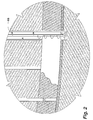
- Figure 1 is an isometric view showing a cross-section of a section of the earth from the surface to slightly below an underground seam of minable materials, such as a seam of coal, and showing some of the basic equipment utilized in the method of this invention.
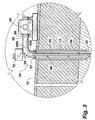
- Figure 2 is an enlarged partial view taken at 2 of Figure 1 showing a bottom hole tool in place and showing the method of removing minable material from the seam.
- Figure 3 is an enlarged partial view taken at 3 of Figure 1 showing, in elevational view, some of the surface equipment as utilized in practicing the method of this invention.
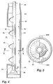
- Figure 4 is an enlarged elevational partially cross-sectional view of a bottom hole tool as employed in this invention.
- Figure 5 is a cross-sectional view taken along the line 5-5 of Figure 4.
- Figure 6 is a diagram showing the flow of water as used in the mining method for removing a minable product from an underground seam.
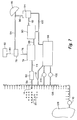
- Figure 7 is a plan view of a system for practicing the method of this invention showing diagrammatically the layout of a field to be mined and the equipment located at the earth's surface for conducting the mining operation.
- Figure 8 is an enlarged cross-sectional view of the discharge head tool as used in the method of this invention.
- the objective is to move to the earth's surface coal from seam 12 without following the usual mining processes, that is, without removing the overburden and then recovering coal that is usually termed "strip mining process", or without conducting underground passageways wherein miners operate.
- the method of this invention is to provide means for recovering coal from seam 12 wherein the surface of the earth is hardly disturbed and wherein it is not necessary for any miner to go below the earth's surface.
- the first step in practicing the method of this invention is to drill a relatively large diameter substantially vertical borehole, which is termed a "recovery hole" indicated by the numeral 14.
- the recovery hole 14 extends from the earth's surface 10 to slightly below coal seam 12.
- the recovery hole is preferably formed utilizing a relatively large diameter surface pipe 16, such as a pipe of about 20 inches in diameter, for a relatively short distance, such as about 20 feet.
- the surface pipe is cased or cemented in the borehole.
- a casing which may typically be 12 inches in diameter, extends within the surface casing through the seam.
- the basic principle of this invention is to fragment coal in coal seam 12 by explosives and to move the fragmented coal from the seam to a bottom hole tool 18 positioned at the lower end of recovery hole 14 by which the fragmented coal is removed.
- a plurality of injection holes 20 are drilled in spaced apart relationship and in a pattern with respect to recovery hole 14. Each of the injection holes 20 is drilled from the earth's surface 10 and into coal seam 12. Explosives are then positioned in the coal seam through the injection holes and the explosives ignited to fragment the coal, after which water is inserted through the injection holes 20 to move the fragmented coal to bottom hole tool 18. All of these steps and the apparatuses used in practicing the steps will now be described.
- bottom hole tool 18 will be described.
- casing 22 Positioned within recovery hole 14 is large diameter casing 22. At the lower end of casing 22, as seen best in Figure 4, is a tubular body 24 which must be larger than the diameter of casing 22. A special reducer coupling is employed to connect the segments.
- Window 32 is in the form of a cut out of the wall of tubular body 24.
- the cut out should be approximately the height of seam 12.
- a shaft 34 Coaxially supported within tubular body 24 is a shaft 34.
- the shaft is supported by a lower bearing 36.
- the shaft 34 may be formed of a length of pipe, such as 4 inch diameter pipe.
- the pipe is then attached to other sections of the diameter pipe the full length of the recovery hole.
- Formed on shaft 34 is an auger blade and in the preferred arrangement as illustrated, the auger is comprised of semicircular segments positioned such that viewed along the vertical axis of the auger, the segments overlap each other.
- the auger blade segments 42 have internally formed teeth 46 on the external peripheral edge.
- tubular body 24 Welded on the exterior of tubular body 24 are vertical reinforcing straps 48A and B. These reinforcing straps are welded to the vertical outside edge of window 32 and serve to resist deflection of the tubular body and extend into the subsoil below coal seam for anchoring.
- a reinforcing bar 47 shaped conformably the interior of said casing, to which are mounted conical shaped steel protrusions 49 which act to help break up any larger pieces of coal or other ore.
- Casing 22 extends upwardly through the surface pipe 16.
- a flange 52 is affixed to the casing. Attached to flange 52 is a tubular elbow member 54, the first end 54A thereof being attached to the flange and the elbow member having a second end 54B that is connected to a short length of pipe 56.
- the intake 58 of dredge pump 60 is secured to the other end of pipe 56.
- Tubular elbow member 54 has an opening 62 that communicates with a housing 64 affixed to the exterior of the elbow member.
- a vertical shaft 66 Positioned within casing 22 is a vertical shaft 66 through which water under pressure is piped and to which are mounted nozzles 68 spaced axially and radially.
- the nozzles extend from one directly above the bottom bearing in the bottom hole tool and thence along the shaft to adjacent the earth's surface.
- shaft 66 extends through opening 62 and through the opening in housing 64 and receives a sealed bearing 70.
- the shaft is then attached to a hydraulic driven speed reducer, which is illustrated emblematical at 72.
- speed reducer 72 By power supplied by speed reducer 72, shaft 66 and thereby nozzles 68, attached to it are rotated.
- the lower end of shaft 66 is affixed to the bottom hole tool shaft 34 to thereby also rotate auger blades 42.
- FIG. 7 A plan view for a basic system for practicing the invention is shown in Figure 7.
- the recovery hole is indicated at 14 and a plurality of injection holes 20 are shown.
- Pipe 56 extending from the recovery hole connects to dredge pump 60 as previously described.
- a slurry line 73 connects to a shaker 74 for separating fragmented coal from a slurry.
- the coal passes by way of conveyor 76 to a rotator breaker 78.
- Rock separated by the rotator breaker is fed by a conveyor 80 to a rock storage refuge 82.
- the separated coal is fed by conveyor 84 to a stacker 86.
- a slurry line 88 feeds to a washing plant 90 where the separated coal is washed.
- conveyor 92 coal is fed to a de-watering screen and drier 94.
- From drier 94 the recovered coal is fed by conveyor 96 to stacker 86.
- a water tank 98 provides a water reservoir. Drainage from the washing plant and de-watering screen are fed by conduits 100 into the watering tank. From the watering tank pumps 102 and 104 supply a distribution pipe 106 that has facilities for connection of water to the input of the injection holes, as well as for the nozzles in the recovery hole.
- a source of water 108 which can be a well, a lake, a river, or the like, is used to provide water for the mining operation.
- Pump 110 connects water to the distribution pipe 106 and can be used to fill tank 98 by way of water supply 112.
- Figure 6 is a flow diagram of water as employed in the system. All water is recycled and the only water loss, as will be described subsequently, is that which is used to fill the seam as coal is removed.
- Injection holes are drilled adjacent the recovery hole and typically spaced, such as about five feet, from the recovery hole. While recovery hole 14 is preferably drilled substantially vertically, the injection holes are preferably drilled to intercept seam 12 perpendicularly thereof. Explosives are placed in the injection holes and detonated to fracture coal from the coal seam. Water is then injected into the injection holes to move the fractured coal to bottom hole tool 18.
- Figure 1 shows the system after the first injection holes nearest the recovery hole have been detonated, providing a clear area 114.
- the fragmented coal in the space between the point of detonation and the recovery hole is moved in the direction toward the recovery hole by the flow of water.
- water is injected into all or a portion of the injection holes to move the fragmented coal to the bottom hole tool 18.
- the coal is carried through open window 32 to contact auger blades 42. Water under pressure ejected by the bottom nozzle 44, helps to move the coal upwardly into the interior of the bottom hole tool 24 and further upwardly into the interior of the casing 22 are thence to the surface.
- the bottom flange 45 provides a buffer to keep the bottom water nozzle 44 from ejecting the coal out of the window of the bottom hole tool. Any fragments of coal that are too large to be carried upwardly by the auger are severed and further fractured by auger blades 42 having teeth 46 thereon to break up the coal and further by the crushing bar 47.
- the hydraulic pressure within the system as well as the rotating auger, the rotating water nozzles in the recovery hole all help to move the coal and slurry to the earth's surface.
- the injection holes which are used for the placement of explosives and then subsequently used for the injection of water, are sealed as further injection holes are employed since water must be injected at the farthest point from the recovery well where fragmented coal exists. Closure or plugging of the injection holes 20 can be accomplished utilizing an inflatable plugging tool.
- the method of this disclosure is preferably practiced in a coal seam that is not horizontal but which has an up slope.
- the recovery hole 14 is positioned at the lowest point in the field to be mined and injection holes are drilled in patterns from the recovery hole 14 up slope of coal seam 12. In this way, water injected into the coal seam to move fragmented coal always moves the coal downwardly in the direction toward the recovery hole.
- a single recovery hole may be employed with a large number of injection holes so that a single recovery hole can be used to mine a relatively large acreage.
- the efficiency of movement begins to decrease.
Landscapes
- Engineering & Computer Science (AREA)
- Mining & Mineral Resources (AREA)
- Life Sciences & Earth Sciences (AREA)
- Geology (AREA)
- General Life Sciences & Earth Sciences (AREA)
- Geochemistry & Mineralogy (AREA)
- Fluid Mechanics (AREA)
- Environmental & Geological Engineering (AREA)
- Physics & Mathematics (AREA)
- Remote Sensing (AREA)
- Earth Drilling (AREA)
- Seasonings (AREA)
- Treatment Of Liquids With Adsorbents In General (AREA)
- Drilling And Exploitation, And Mining Machines And Methods (AREA)
- Excavating Of Shafts Or Tunnels (AREA)
- Processing Of Solid Wastes (AREA)
- Analysing Materials By The Use Of Radiation (AREA)
- Artificial Fish Reefs (AREA)
- Perforating, Stamping-Out Or Severing By Means Other Than Cutting (AREA)
Applications Claiming Priority (2)
| Application Number | Priority Date | Filing Date | Title |
|---|---|---|---|
| US08/438,186 US5531507A (en) | 1995-05-09 | 1995-05-09 | Method of removing a minable product from an underground seam and bottom hole tool |
| US438186 | 1995-05-09 |
Publications (3)
| Publication Number | Publication Date |
|---|---|
| EP0742345A2 true EP0742345A2 (de) | 1996-11-13 |
| EP0742345A3 EP0742345A3 (de) | 1998-02-04 |
| EP0742345B1 EP0742345B1 (de) | 2001-10-17 |
Family
ID=23739609
Family Applications (1)
| Application Number | Title | Priority Date | Filing Date |
|---|---|---|---|
| EP96303200A Expired - Lifetime EP0742345B1 (de) | 1995-05-09 | 1996-05-08 | Verfahren und Vorrichtung zum Gewinnen eines Bodenschatzes aus einer Lagerstätte |
Country Status (11)
| Country | Link |
|---|---|
| US (1) | US5531507A (de) |
| EP (1) | EP0742345B1 (de) |
| AT (1) | ATE207186T1 (de) |
| AU (1) | AU700483B2 (de) |
| BR (1) | BR9602200A (de) |
| CA (1) | CA2176100C (de) |
| DE (1) | DE69615912T2 (de) |
| DK (1) | DK0742345T3 (de) |
| ES (1) | ES2165471T3 (de) |
| IN (1) | IN186629B (de) |
| PT (1) | PT742345E (de) |
Families Citing this family (8)
| Publication number | Priority date | Publication date | Assignee | Title |
|---|---|---|---|---|
| US5865261A (en) * | 1997-03-03 | 1999-02-02 | Baker Hughes Incorporated | Balanced or underbalanced drilling method and apparatus |
| CN102434098B (zh) * | 2011-12-01 | 2014-05-28 | 中国煤炭科工集团太原研究院 | 煤矿用液压五臂锚杆钻车 |
| CN102518405B (zh) * | 2011-12-01 | 2014-03-19 | 中国煤炭科工集团太原研究院 | 集成式真空负压三级除尘系统 |
| CN104879166B (zh) * | 2015-05-08 | 2019-05-14 | 山西潞安环保能源开发股份有限公司 | 一种大采高综采工作面台阶式自掘回撤通道方法 |
| CN105804716B (zh) * | 2016-05-12 | 2019-05-17 | 中国矿业大学(北京) | 一种爆炸致裂抽采页岩气的方法及激裂弹 |
| CN109296319B (zh) * | 2018-11-16 | 2020-01-14 | 河南理工大学 | 一种瓦斯抽采孔钻设装置 |
| CN110552645B (zh) * | 2019-09-30 | 2024-06-18 | 北京三一智造科技有限公司 | 钻具 |
| CN113107513B (zh) * | 2021-04-15 | 2023-03-21 | 中铁工程装备集团有限公司 | 破岩的隧道施工方法 |
Family Cites Families (17)
| Publication number | Priority date | Publication date | Assignee | Title |
|---|---|---|---|---|
| US842364A (en) * | 1905-12-04 | 1907-01-29 | Edward L Leser | Dredge. |
| US3050289A (en) * | 1960-06-27 | 1962-08-21 | Phillips Petroleum Co | Heavy hydrocarbon recovery from petroliferous deposits by hydraulic washing |
| US4092045A (en) * | 1975-10-06 | 1978-05-30 | Sullivan Thomas M | Subterranean hydraulic mining method |
| US4226475A (en) * | 1978-04-19 | 1980-10-07 | Frosch Robert A | Underground mineral extraction |
| US4252200A (en) * | 1979-02-16 | 1981-02-24 | Peterson James R | Sampling device |
| US4330155A (en) * | 1980-03-26 | 1982-05-18 | Santa Fe International Corporation | Bore hole mining |
| US4348058A (en) * | 1980-04-01 | 1982-09-07 | Slurry Mining Engineering Inc. | Method and apparatus for slurry borehole mining |
| DE3108425A1 (de) * | 1981-03-06 | 1982-09-23 | Basf Ag, 6700 Ludwigshafen | Verfahren zur erschliessung sehr tief liegender kohlefloeze |
| US4411474A (en) * | 1981-05-20 | 1983-10-25 | Texasgulf Inc. | Solution mining of an inclined structure |
| US4396075A (en) * | 1981-06-23 | 1983-08-02 | Wood Edward T | Multiple branch completion with common drilling and casing template |
| US4433739A (en) * | 1982-02-08 | 1984-02-28 | Gte Laboratories, Inc. | Mining drill |
| US4421182A (en) * | 1982-03-16 | 1983-12-20 | Moody Arlin R | Combination clean-out and drilling tool |
| US4449593A (en) * | 1982-09-29 | 1984-05-22 | Standard Oil Company | Guide for sidewall coring bit assembly |
| US4629011A (en) * | 1985-08-12 | 1986-12-16 | Baker Oil Tools, Inc. | Method and apparatus for taking core samples from a subterranean well side wall |
| US4804050A (en) * | 1987-04-30 | 1989-02-14 | K-V Associates, Inc. | Method of underground fluid sampling |
| WO1990003494A1 (en) * | 1988-09-28 | 1990-04-05 | Lawrence Reginald Baster | Method and installation for mining |
| US5139312A (en) * | 1991-04-09 | 1992-08-18 | Jackson Daryl L | Method and apparatus removing a mineable product from an underground seam |
-
1995
- 1995-05-09 US US08/438,186 patent/US5531507A/en not_active Expired - Fee Related
-
1996
- 1996-02-16 IN IN94BO1996 patent/IN186629B/en unknown
- 1996-05-08 ES ES96303200T patent/ES2165471T3/es not_active Expired - Lifetime
- 1996-05-08 DE DE69615912T patent/DE69615912T2/de not_active Expired - Fee Related
- 1996-05-08 CA CA002176100A patent/CA2176100C/en not_active Expired - Fee Related
- 1996-05-08 DK DK96303200T patent/DK0742345T3/da active
- 1996-05-08 AT AT96303200T patent/ATE207186T1/de not_active IP Right Cessation
- 1996-05-08 PT PT96303200T patent/PT742345E/pt unknown
- 1996-05-08 EP EP96303200A patent/EP0742345B1/de not_active Expired - Lifetime
- 1996-05-09 AU AU52191/96A patent/AU700483B2/en not_active Ceased
- 1996-05-09 BR BR9602200A patent/BR9602200A/pt not_active IP Right Cessation
Also Published As
| Publication number | Publication date |
|---|---|
| CA2176100C (en) | 2007-04-17 |
| DE69615912D1 (de) | 2001-11-22 |
| AU5219196A (en) | 1996-11-21 |
| ATE207186T1 (de) | 2001-11-15 |
| CA2176100A1 (en) | 1996-11-10 |
| EP0742345A3 (de) | 1998-02-04 |
| US5531507A (en) | 1996-07-02 |
| IN186629B (de) | 2001-10-13 |
| DE69615912T2 (de) | 2002-06-13 |
| AU700483B2 (en) | 1999-01-07 |
| ES2165471T3 (es) | 2002-03-16 |
| DK0742345T3 (da) | 2002-02-11 |
| EP0742345B1 (de) | 2001-10-17 |
| PT742345E (pt) | 2002-02-28 |
| BR9602200A (pt) | 1998-04-07 |
Similar Documents
| Publication | Publication Date | Title |
|---|---|---|
| US8313152B2 (en) | Recovery of bitumen by hydraulic excavation | |
| ES2297429T3 (es) | Metodo de construccion de un intercambiador de calor geotermico. | |
| US5879057A (en) | Horizontal remote mining system, and method | |
| US4319784A (en) | Apparatus for water jet and impact drilling and mining | |
| US20140117739A1 (en) | Mining Method for Gassy and Low Permeability Coal Seams | |
| CA2752461C (en) | Enhanced permeability subterranean fluid recovery system and methods | |
| WO2010074980A1 (en) | Method and apparatus for increasing well productivity | |
| US20080164066A1 (en) | Method and device for producing a cased string bore | |
| US12098636B2 (en) | Underground mining methods via boreholes and multilateral blast-holes | |
| CN118391026B (zh) | 一种井硐扩展采矿系统及采矿方法 | |
| EP0742345B1 (de) | Verfahren und Vorrichtung zum Gewinnen eines Bodenschatzes aus einer Lagerstätte | |
| CA2076239C (en) | Method of removing a mineable product from an underground seam | |
| US20130106166A1 (en) | Horizontal Borehole Mining System and Method | |
| ES3032776T3 (en) | Method and system for mining | |
| RU2059073C1 (ru) | Способ разработки месторождений полезных ископаемых | |
| CA1129446A (en) | Method and apparatus for drilling and mining | |
| KR101237749B1 (ko) | 쉴드공법에 사용되는 추진장치의 헤드 | |
| RU2090754C1 (ru) | Способ открытой разработки месторождений полезных ископаемых | |
| RU2857639C1 (ru) | Способ скважинной добычи полезных ископаемых и устройство для его осуществления | |
| RU2109949C1 (ru) | Способ скважинной гидродобычи полезных ископаемых и скважинный гидродобычной агрегат для его осуществления | |
| RU2326284C1 (ru) | Способ бестраншейной прокладки трубопровода | |
| CA1234351A (en) | Tar sands treatment | |
| CN1163340A (zh) | 建筑基础人工挖孔灌注桩快速施工工艺 | |
| BR112024012858B1 (pt) | Métodos de mineração subterrânea através de furos e furos de explosão multilaterais | |
| WO2025171364A1 (en) | Methods for efficient mining and leaching of minerals utilizing advanced directional drilling technology and extraction via boreholes |
Legal Events
| Date | Code | Title | Description |
|---|---|---|---|
| PUAI | Public reference made under article 153(3) epc to a published international application that has entered the european phase |
Free format text: ORIGINAL CODE: 0009012 |
|
| AK | Designated contracting states |
Kind code of ref document: A2 Designated state(s): AT BE CH DE DK ES FI FR GB GR IE IT LI LU NL PT SE |
|
| PUAL | Search report despatched |
Free format text: ORIGINAL CODE: 0009013 |
|
| AK | Designated contracting states |
Kind code of ref document: A3 Designated state(s): AT BE CH DE DK ES FI FR GB GR IE IT LI LU NL PT SE |
|
| 17P | Request for examination filed |
Effective date: 19980715 |
|
| GRAG | Despatch of communication of intention to grant |
Free format text: ORIGINAL CODE: EPIDOS AGRA |
|
| 17Q | First examination report despatched |
Effective date: 20001219 |
|
| GRAG | Despatch of communication of intention to grant |
Free format text: ORIGINAL CODE: EPIDOS AGRA |
|
| GRAH | Despatch of communication of intention to grant a patent |
Free format text: ORIGINAL CODE: EPIDOS IGRA |
|
| GRAH | Despatch of communication of intention to grant a patent |
Free format text: ORIGINAL CODE: EPIDOS IGRA |
|
| GRAA | (expected) grant |
Free format text: ORIGINAL CODE: 0009210 |
|
| AK | Designated contracting states |
Kind code of ref document: B1 Designated state(s): AT BE CH DE DK ES FI FR GB GR IE IT LI LU NL PT SE |
|
| REF | Corresponds to: |
Ref document number: 207186 Country of ref document: AT Date of ref document: 20011115 Kind code of ref document: T |
|
| REG | Reference to a national code |
Ref country code: CH Ref legal event code: EP |
|
| REG | Reference to a national code |
Ref country code: IE Ref legal event code: FG4D |
|
| REF | Corresponds to: |
Ref document number: 69615912 Country of ref document: DE Date of ref document: 20011122 |
|
| ET | Fr: translation filed | ||
| REG | Reference to a national code |
Ref country code: CH Ref legal event code: NV Representative=s name: AMMANN PATENTANWAELTE AG BERN |
|
| REG | Reference to a national code |
Ref country code: GB Ref legal event code: IF02 |
|
| REG | Reference to a national code |
Ref country code: DK Ref legal event code: T3 |
|
| REG | Reference to a national code |
Ref country code: PT Ref legal event code: SC4A Free format text: AVAILABILITY OF NATIONAL TRANSLATION Effective date: 20011203 |
|
| REG | Reference to a national code |
Ref country code: ES Ref legal event code: FG2A Ref document number: 2165471 Country of ref document: ES Kind code of ref document: T3 |
|
| REG | Reference to a national code |
Ref country code: GR Ref legal event code: EP Ref document number: 20020400142 Country of ref document: GR |
|
| PLBE | No opposition filed within time limit |
Free format text: ORIGINAL CODE: 0009261 |
|
| STAA | Information on the status of an ep patent application or granted ep patent |
Free format text: STATUS: NO OPPOSITION FILED WITHIN TIME LIMIT |
|
| 26N | No opposition filed | ||
| PGFP | Annual fee paid to national office [announced via postgrant information from national office to epo] |
Ref country code: PT Payment date: 20050419 Year of fee payment: 10 |
|
| PGFP | Annual fee paid to national office [announced via postgrant information from national office to epo] |
Ref country code: IE Payment date: 20050421 Year of fee payment: 10 |
|
| PGFP | Annual fee paid to national office [announced via postgrant information from national office to epo] |
Ref country code: SE Payment date: 20050516 Year of fee payment: 10 |
|
| PGFP | Annual fee paid to national office [announced via postgrant information from national office to epo] |
Ref country code: LU Payment date: 20050519 Year of fee payment: 10 |
|
| PGFP | Annual fee paid to national office [announced via postgrant information from national office to epo] |
Ref country code: CH Payment date: 20050530 Year of fee payment: 10 |
|
| PGFP | Annual fee paid to national office [announced via postgrant information from national office to epo] |
Ref country code: GR Payment date: 20050531 Year of fee payment: 10 |
|
| PGFP | Annual fee paid to national office [announced via postgrant information from national office to epo] |
Ref country code: FR Payment date: 20060428 Year of fee payment: 11 |
|
| PGFP | Annual fee paid to national office [announced via postgrant information from national office to epo] |
Ref country code: GB Payment date: 20060429 Year of fee payment: 11 |
|
| PGFP | Annual fee paid to national office [announced via postgrant information from national office to epo] |
Ref country code: FI Payment date: 20060503 Year of fee payment: 11 |
|
| PGFP | Annual fee paid to national office [announced via postgrant information from national office to epo] |
Ref country code: ES Payment date: 20060505 Year of fee payment: 11 Ref country code: BE Payment date: 20060505 Year of fee payment: 11 |
|
| PG25 | Lapsed in a contracting state [announced via postgrant information from national office to epo] |
Ref country code: IE Free format text: LAPSE BECAUSE OF NON-PAYMENT OF DUE FEES Effective date: 20060508 |
|
| PGFP | Annual fee paid to national office [announced via postgrant information from national office to epo] |
Ref country code: AT Payment date: 20060508 Year of fee payment: 11 |
|
| PG25 | Lapsed in a contracting state [announced via postgrant information from national office to epo] |
Ref country code: SE Free format text: LAPSE BECAUSE OF NON-PAYMENT OF DUE FEES Effective date: 20060509 |
|
| PGFP | Annual fee paid to national office [announced via postgrant information from national office to epo] |
Ref country code: DK Payment date: 20060517 Year of fee payment: 11 |
|
| PGFP | Annual fee paid to national office [announced via postgrant information from national office to epo] |
Ref country code: NL Payment date: 20060530 Year of fee payment: 11 |
|
| PG25 | Lapsed in a contracting state [announced via postgrant information from national office to epo] |
Ref country code: LI Free format text: LAPSE BECAUSE OF NON-PAYMENT OF DUE FEES Effective date: 20060531 Ref country code: CH Free format text: LAPSE BECAUSE OF NON-PAYMENT OF DUE FEES Effective date: 20060531 |
|
| PGFP | Annual fee paid to national office [announced via postgrant information from national office to epo] |
Ref country code: IT Payment date: 20060531 Year of fee payment: 11 |
|
| PGFP | Annual fee paid to national office [announced via postgrant information from national office to epo] |
Ref country code: DE Payment date: 20060728 Year of fee payment: 11 |
|
| PG25 | Lapsed in a contracting state [announced via postgrant information from national office to epo] |
Ref country code: PT Free format text: LAPSE BECAUSE OF NON-PAYMENT OF DUE FEES Effective date: 20061108 |
|
| REG | Reference to a national code |
Ref country code: PT Ref legal event code: MM4A Free format text: LAPSE DUE TO NON-PAYMENT OF FEES Effective date: 20061108 |
|
| REG | Reference to a national code |
Ref country code: CH Ref legal event code: PL |
|
| EUG | Se: european patent has lapsed | ||
| BERE | Be: lapsed |
Owner name: *JACKSON DARYL L. Effective date: 20070531 |
|
| REG | Reference to a national code |
Ref country code: DK Ref legal event code: EBP |
|
| GBPC | Gb: european patent ceased through non-payment of renewal fee |
Effective date: 20070508 |
|
| PG25 | Lapsed in a contracting state [announced via postgrant information from national office to epo] |
Ref country code: NL Free format text: LAPSE BECAUSE OF NON-PAYMENT OF DUE FEES Effective date: 20071201 Ref country code: FI Free format text: LAPSE BECAUSE OF NON-PAYMENT OF DUE FEES Effective date: 20070508 |
|
| NLV4 | Nl: lapsed or anulled due to non-payment of the annual fee |
Effective date: 20071201 |
|
| PG25 | Lapsed in a contracting state [announced via postgrant information from national office to epo] |
Ref country code: AT Free format text: LAPSE BECAUSE OF NON-PAYMENT OF DUE FEES Effective date: 20070508 |
|
| REG | Reference to a national code |
Ref country code: FR Ref legal event code: ST Effective date: 20080131 |
|
| PG25 | Lapsed in a contracting state [announced via postgrant information from national office to epo] |
Ref country code: BE Free format text: LAPSE BECAUSE OF NON-PAYMENT OF DUE FEES Effective date: 20070531 |
|
| PG25 | Lapsed in a contracting state [announced via postgrant information from national office to epo] |
Ref country code: DK Free format text: LAPSE BECAUSE OF NON-PAYMENT OF DUE FEES Effective date: 20070531 Ref country code: DE Free format text: LAPSE BECAUSE OF NON-PAYMENT OF DUE FEES Effective date: 20071201 |
|
| PG25 | Lapsed in a contracting state [announced via postgrant information from national office to epo] |
Ref country code: GB Free format text: LAPSE BECAUSE OF NON-PAYMENT OF DUE FEES Effective date: 20070508 |
|
| PG25 | Lapsed in a contracting state [announced via postgrant information from national office to epo] |
Ref country code: LU Free format text: LAPSE BECAUSE OF NON-PAYMENT OF DUE FEES Effective date: 20060508 Ref country code: FR Free format text: LAPSE BECAUSE OF NON-PAYMENT OF DUE FEES Effective date: 20070531 |
|
| REG | Reference to a national code |
Ref country code: ES Ref legal event code: FD2A Effective date: 20070509 |
|
| PG25 | Lapsed in a contracting state [announced via postgrant information from national office to epo] |
Ref country code: GR Free format text: LAPSE BECAUSE OF NON-PAYMENT OF DUE FEES Effective date: 20061205 Ref country code: ES Free format text: LAPSE BECAUSE OF NON-PAYMENT OF DUE FEES Effective date: 20070509 |
|
| PG25 | Lapsed in a contracting state [announced via postgrant information from national office to epo] |
Ref country code: IT Free format text: LAPSE BECAUSE OF NON-PAYMENT OF DUE FEES Effective date: 20070508 |