EP0741441A2 - A charging device for a battery - Google Patents
A charging device for a battery Download PDFInfo
- Publication number
- EP0741441A2 EP0741441A2 EP96106755A EP96106755A EP0741441A2 EP 0741441 A2 EP0741441 A2 EP 0741441A2 EP 96106755 A EP96106755 A EP 96106755A EP 96106755 A EP96106755 A EP 96106755A EP 0741441 A2 EP0741441 A2 EP 0741441A2
- Authority
- EP
- European Patent Office
- Prior art keywords
- charging
- charging device
- section
- charger
- vehicle
- Prior art date
- Legal status (The legal status is an assumption and is not a legal conclusion. Google has not performed a legal analysis and makes no representation as to the accuracy of the status listed.)
- Withdrawn
Links
Images


Classifications
-
- B—PERFORMING OPERATIONS; TRANSPORTING
- B62—LAND VEHICLES FOR TRAVELLING OTHERWISE THAN ON RAILS
- B62M—RIDER PROPULSION OF WHEELED VEHICLES OR SLEDGES; POWERED PROPULSION OF SLEDGES OR SINGLE-TRACK CYCLES; TRANSMISSIONS SPECIALLY ADAPTED FOR SUCH VEHICLES
- B62M6/00—Rider propulsion of wheeled vehicles with additional source of power, e.g. combustion engine or electric motor
- B62M6/40—Rider propelled cycles with auxiliary electric motor
- B62M6/55—Rider propelled cycles with auxiliary electric motor power-driven at crank shafts parts
-
- B—PERFORMING OPERATIONS; TRANSPORTING
- B60—VEHICLES IN GENERAL
- B60L—PROPULSION OF ELECTRICALLY-PROPELLED VEHICLES; SUPPLYING ELECTRIC POWER FOR AUXILIARY EQUIPMENT OF ELECTRICALLY-PROPELLED VEHICLES; ELECTRODYNAMIC BRAKE SYSTEMS FOR VEHICLES IN GENERAL; MAGNETIC SUSPENSION OR LEVITATION FOR VEHICLES; MONITORING OPERATING VARIABLES OF ELECTRICALLY-PROPELLED VEHICLES; ELECTRIC SAFETY DEVICES FOR ELECTRICALLY-PROPELLED VEHICLES
- B60L50/00—Electric propulsion with power supplied within the vehicle
- B60L50/20—Electric propulsion with power supplied within the vehicle using propulsion power generated by humans or animals
-
- B—PERFORMING OPERATIONS; TRANSPORTING
- B60—VEHICLES IN GENERAL
- B60L—PROPULSION OF ELECTRICALLY-PROPELLED VEHICLES; SUPPLYING ELECTRIC POWER FOR AUXILIARY EQUIPMENT OF ELECTRICALLY-PROPELLED VEHICLES; ELECTRODYNAMIC BRAKE SYSTEMS FOR VEHICLES IN GENERAL; MAGNETIC SUSPENSION OR LEVITATION FOR VEHICLES; MONITORING OPERATING VARIABLES OF ELECTRICALLY-PROPELLED VEHICLES; ELECTRIC SAFETY DEVICES FOR ELECTRICALLY-PROPELLED VEHICLES
- B60L50/00—Electric propulsion with power supplied within the vehicle
- B60L50/50—Electric propulsion with power supplied within the vehicle using propulsion power supplied by batteries or fuel cells
- B60L50/53—Electric propulsion with power supplied within the vehicle using propulsion power supplied by batteries or fuel cells in combination with an external power supply, e.g. from overhead contact lines
-
- B—PERFORMING OPERATIONS; TRANSPORTING
- B60—VEHICLES IN GENERAL
- B60L—PROPULSION OF ELECTRICALLY-PROPELLED VEHICLES; SUPPLYING ELECTRIC POWER FOR AUXILIARY EQUIPMENT OF ELECTRICALLY-PROPELLED VEHICLES; ELECTRODYNAMIC BRAKE SYSTEMS FOR VEHICLES IN GENERAL; MAGNETIC SUSPENSION OR LEVITATION FOR VEHICLES; MONITORING OPERATING VARIABLES OF ELECTRICALLY-PROPELLED VEHICLES; ELECTRIC SAFETY DEVICES FOR ELECTRICALLY-PROPELLED VEHICLES
- B60L53/00—Methods of charging batteries, specially adapted for electric vehicles; Charging stations or on-board charging equipment therefor; Exchange of energy storage elements in electric vehicles
- B60L53/10—Methods of charging batteries, specially adapted for electric vehicles; Charging stations or on-board charging equipment therefor; Exchange of energy storage elements in electric vehicles characterised by the energy transfer between the charging station and the vehicle
- B60L53/12—Inductive energy transfer
- B60L53/124—Detection or removal of foreign bodies
-
- B—PERFORMING OPERATIONS; TRANSPORTING
- B62—LAND VEHICLES FOR TRAVELLING OTHERWISE THAN ON RAILS
- B62M—RIDER PROPULSION OF WHEELED VEHICLES OR SLEDGES; POWERED PROPULSION OF SLEDGES OR SINGLE-TRACK CYCLES; TRANSMISSIONS SPECIALLY ADAPTED FOR SUCH VEHICLES
- B62M6/00—Rider propulsion of wheeled vehicles with additional source of power, e.g. combustion engine or electric motor
- B62M6/80—Accessories, e.g. power sources; Arrangements thereof
- B62M6/90—Batteries
-
- H—ELECTRICITY
- H02—GENERATION; CONVERSION OR DISTRIBUTION OF ELECTRIC POWER
- H02J—ELECTRIC POWER NETWORKS; CIRCUIT ARRANGEMENTS OR SYSTEMS FOR SUPPLYING OR DISTRIBUTING ELECTRIC POWER; SYSTEMS FOR STORING ELECTRIC ENERGY
- H02J50/00—Circuit arrangements or systems for wireless supply or distribution of electric power
- H02J50/005—Mechanical details of housing or structure aiming to accommodate the power transfer means, e.g. mechanical integration of coils, antennas or transducers into emitting or receiving devices
-
- H—ELECTRICITY
- H02—GENERATION; CONVERSION OR DISTRIBUTION OF ELECTRIC POWER
- H02J—ELECTRIC POWER NETWORKS; CIRCUIT ARRANGEMENTS OR SYSTEMS FOR SUPPLYING OR DISTRIBUTING ELECTRIC POWER; SYSTEMS FOR STORING ELECTRIC ENERGY
- H02J50/00—Circuit arrangements or systems for wireless supply or distribution of electric power
- H02J50/10—Circuit arrangements or systems for wireless supply or distribution of electric power using inductive coupling
-
- H—ELECTRICITY
- H02—GENERATION; CONVERSION OR DISTRIBUTION OF ELECTRIC POWER
- H02J—ELECTRIC POWER NETWORKS; CIRCUIT ARRANGEMENTS OR SYSTEMS FOR SUPPLYING OR DISTRIBUTING ELECTRIC POWER; SYSTEMS FOR STORING ELECTRIC ENERGY
- H02J7/00—Circuit arrangements for charging or discharging batteries or for supplying loads from batteries
- H02J7/70—Circuit arrangements for charging or discharging batteries or for supplying loads from batteries characterised by the mechanical construction
-
- B—PERFORMING OPERATIONS; TRANSPORTING
- B60—VEHICLES IN GENERAL
- B60K—ARRANGEMENT OR MOUNTING OF PROPULSION UNITS OR OF TRANSMISSIONS IN VEHICLES; ARRANGEMENT OR MOUNTING OF PLURAL DIVERSE PRIME-MOVERS IN VEHICLES; AUXILIARY DRIVES FOR VEHICLES; INSTRUMENTATION OR DASHBOARDS FOR VEHICLES; ARRANGEMENTS IN CONNECTION WITH COOLING, AIR INTAKE, GAS EXHAUST OR FUEL SUPPLY OF PROPULSION UNITS IN VEHICLES
- B60K1/00—Arrangement or mounting of electrical propulsion units
- B60K1/04—Arrangement or mounting of electrical propulsion units of the electric storage means for propulsion
-
- B—PERFORMING OPERATIONS; TRANSPORTING
- B60—VEHICLES IN GENERAL
- B60L—PROPULSION OF ELECTRICALLY-PROPELLED VEHICLES; SUPPLYING ELECTRIC POWER FOR AUXILIARY EQUIPMENT OF ELECTRICALLY-PROPELLED VEHICLES; ELECTRODYNAMIC BRAKE SYSTEMS FOR VEHICLES IN GENERAL; MAGNETIC SUSPENSION OR LEVITATION FOR VEHICLES; MONITORING OPERATING VARIABLES OF ELECTRICALLY-PROPELLED VEHICLES; ELECTRIC SAFETY DEVICES FOR ELECTRICALLY-PROPELLED VEHICLES
- B60L2200/00—Type of vehicles
- B60L2200/12—Bikes
-
- B—PERFORMING OPERATIONS; TRANSPORTING
- B60—VEHICLES IN GENERAL
- B60L—PROPULSION OF ELECTRICALLY-PROPELLED VEHICLES; SUPPLYING ELECTRIC POWER FOR AUXILIARY EQUIPMENT OF ELECTRICALLY-PROPELLED VEHICLES; ELECTRODYNAMIC BRAKE SYSTEMS FOR VEHICLES IN GENERAL; MAGNETIC SUSPENSION OR LEVITATION FOR VEHICLES; MONITORING OPERATING VARIABLES OF ELECTRICALLY-PROPELLED VEHICLES; ELECTRIC SAFETY DEVICES FOR ELECTRICALLY-PROPELLED VEHICLES
- B60L2270/00—Problem solutions or means not otherwise provided for
- B60L2270/30—Preventing theft during charging
- B60L2270/36—Preventing theft during charging of vehicles
-
- B—PERFORMING OPERATIONS; TRANSPORTING
- B60—VEHICLES IN GENERAL
- B60Y—INDEXING SCHEME RELATING TO ASPECTS CROSS-CUTTING VEHICLE TECHNOLOGY
- B60Y2200/00—Type of vehicle
- B60Y2200/10—Road Vehicles
- B60Y2200/12—Motorcycles, Trikes; Quads; Scooters
-
- Y—GENERAL TAGGING OF NEW TECHNOLOGICAL DEVELOPMENTS; GENERAL TAGGING OF CROSS-SECTIONAL TECHNOLOGIES SPANNING OVER SEVERAL SECTIONS OF THE IPC; TECHNICAL SUBJECTS COVERED BY FORMER USPC CROSS-REFERENCE ART COLLECTIONS [XRACs] AND DIGESTS
- Y02—TECHNOLOGIES OR APPLICATIONS FOR MITIGATION OR ADAPTATION AGAINST CLIMATE CHANGE
- Y02T—CLIMATE CHANGE MITIGATION TECHNOLOGIES RELATED TO TRANSPORTATION
- Y02T10/00—Road transport of goods or passengers
- Y02T10/60—Other road transportation technologies with climate change mitigation effect
- Y02T10/70—Energy storage systems for electromobility, e.g. batteries
-
- Y—GENERAL TAGGING OF NEW TECHNOLOGICAL DEVELOPMENTS; GENERAL TAGGING OF CROSS-SECTIONAL TECHNOLOGIES SPANNING OVER SEVERAL SECTIONS OF THE IPC; TECHNICAL SUBJECTS COVERED BY FORMER USPC CROSS-REFERENCE ART COLLECTIONS [XRACs] AND DIGESTS
- Y02—TECHNOLOGIES OR APPLICATIONS FOR MITIGATION OR ADAPTATION AGAINST CLIMATE CHANGE
- Y02T—CLIMATE CHANGE MITIGATION TECHNOLOGIES RELATED TO TRANSPORTATION
- Y02T10/00—Road transport of goods or passengers
- Y02T10/60—Other road transportation technologies with climate change mitigation effect
- Y02T10/7072—Electromobility specific charging systems or methods for batteries, ultracapacitors, supercapacitors or double-layer capacitors
-
- Y—GENERAL TAGGING OF NEW TECHNOLOGICAL DEVELOPMENTS; GENERAL TAGGING OF CROSS-SECTIONAL TECHNOLOGIES SPANNING OVER SEVERAL SECTIONS OF THE IPC; TECHNICAL SUBJECTS COVERED BY FORMER USPC CROSS-REFERENCE ART COLLECTIONS [XRACs] AND DIGESTS
- Y02—TECHNOLOGIES OR APPLICATIONS FOR MITIGATION OR ADAPTATION AGAINST CLIMATE CHANGE
- Y02T—CLIMATE CHANGE MITIGATION TECHNOLOGIES RELATED TO TRANSPORTATION
- Y02T90/00—Enabling technologies or technologies with a potential or indirect contribution to GHG emissions mitigation
- Y02T90/10—Technologies relating to charging of electric vehicles
- Y02T90/14—Plug-in electric vehicles
Definitions
- the present invention relates to a charging device for a battery of an electrically driven two wheel vehicle, in particular an electrical power assisted bicycle.
- the charging of the battery is repeatedly performed during non-use stage with a charger connected, for example, to a home electric power source.
- the charging of the battery may be carried out after separation of the battery from the vehicle main body or while retaining the battery on the vehicle main body. In either case, there involves merits and demerits depending on the place and environment where the charging is performed.
- the conventional construction has been generally such that both types of charging may be adopted.
- this objective is solved for a charging device as indicated above by a stationary charger having a grasping section for holding said vehicle and a charging section for charging said battery.
- said charging arm is pivotably linked to a charger main body connected to a stationary mounting bracket.
- said grasping section When said grasping section is provided with a locking mechanism for locking said vehicle being held by said grasping section the position of this vehicle is secured.
- the charging is performed under the conditions in which the electric vehicle is positioned at a location where the charger is disposed, in which a portion of the vehicle is held with the grasping section of the charging arm, and in which the power supplying member is electrically coupled with the power receiving member.
- the charger main body having the charging arm provided with the grasping section is installed in a parking area and since the charger main body is electrically coupled with the battery upon holding the vehicle main body with the grasping section of the charging arm, the battery can be charged while keeping the battery mounted on the vehicle without requiring a disturbing extension cord and without requiring troublesome attaching and detaching works. Further, during the charging, the vehicle body is held with the charging arm and is mechanically fixed, so that damages by felling can be prevented.
- both the electrical connection and the mechanical fixing can be achieved simultaneously.
- the coil on the power receiving side on the vehicle is disposed opposite the coil on the power supplying side on the charger with a space being defined therebetween and since the charging electric power is supplied by a magnetic coupling therebetween without direct contact therebetween, problems, such as fouling of a contact portion and failure of contact due to rust which would be apt to be caused in the case of an electrical connection by direct contact, can be avoided.
- the charging arm since the charging arm is capable of being rotated between a charging position and an accommodated position, the charging arm can be positioned at a vertical wall side during non-use, so that the problem of obstacle by the charging arm can be avoided.
- Figs. 1 through 4 are illustrations explanatory of a charging device for an electric bicycle according to one embodiment of the present invention.
- Fig. 1 is a plan view of the construction of the charging device
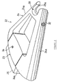
- Fig. 2 is a perspective of the charging device
- Fig. 3 is a schematic view showing the state of the charging device during use
- Fig. 4 is a side view of the electric bicycle.
- the reference numeral 1 designates an electric bicycle having a body frame 2 composed of a longitudinally extending main frame 2a of a nearly rectangular box-like form, a pair of left and right rear frames 2b each rearwardly extending from the main frame 2a, and a seat tube 2c upwardly extending from the main frame 2a.
- the main body 2a has a lower end connected by a chain stay 2d to a rear end of the rear frame 2b.
- the chain stay 2d is integrally connected to the rear frame 2b through a bracket 2f.
- a front fork 4 Rotatably received in a front end 2e of the main frame 2a is a front fork 4 to which a front wheel 3 is rotatably supported.
- the front fork 4 has an upper end to which a steering handle 5 is mounted.
- a rear wheel 6 is rotatably supported by the bracket 2f.
- a seat post 8 provided with a saddle 7 is received in the seat tube 2c such that the height thereof is adjusted at a desired level.
- the main frame 2a has a lower end to which a crankshaft 10 is rotatably supported.
- the crankshaft 10 has both ends each provided with a pedal 12 through a crank 11.
- a chain is connected through a chain sprocket (not shown) to the crankshaft and is also connected to the rear wheel 6.
- a rear wheel driving device 15 which includes an electric motor for supplying an auxiliary driving force to the rear wheel 6, a battery 17 for supplying an electric source to the motor 16, and a controller 18 for controlling the driving force of the electric motor to a value corresponding to the pedaling force.
- the pedaling force on the pedals is combined with the auxiliary driving force from the electric motor 16 and the combined force is transmitted to the rear wheel 6 through the chain.
- the controller 18 and the battery 17 are arranged within the main frame 2a along the longitudinal direction thereof, while the electric motor 16 is disposed in a rear portion of the main frame 2a with its output shaft being oriented downward.
- the output shaft (not shown) of the electric motor 16 is connected to the chain sprocket through a deceleration gearing mechanism 19.
- the seat tube 2c of the body frame has an upper end on which positive and negative poles power receiving terminals 21 and 21 serving as a power receiving member constituting a power receiving side of a charging device 20 are provided.
- the power receiving terminals 21 and 21 slightly protrude from the peripheral surface of the seat tube 2c and mounted on the tube 2c through an insulating member (not shown) interposed therebetween. Respective terminals 21 and 21 are electrically coupled with the charging terminals of the battery 17 through lead wires 21a and 21a.
- the charging device 20 has a charger 22 which constitutes a power supplying side thereof and which includes a rectangular parallelepiped charger main body 23 coupled to the electric source and a charging arm 24 connected to the charger main body 23 and having a generally V-like form as viewed on a plan view.
- the charger main body 23 is fixedly secured through a mounting bracket 25 to a vertical wall portion 26 of a parking area for the electric bicycle 1 at nearly the same level as those of the power receiving terminals 21 and 21 of the seat tube 2c.
- the parking area may be located at any desired place such as on a side of a house, in a barn or in a garden.
- the vertical wall may be substituted by a separately constructed stand. There are no specific limitations on the place and the wall.
- grasping section 28 and said charging section or said supplying terminals 29 may be separated from each other.
- the charging arm 24 has left and right arm sections 24a extending from a root section 24b which is pivoted through a supporting member 27 to left and right side surfaces 23a of the charger main body 23, so that the charging arm 24 is rotatable between a charging position where the arm 24 is oriented in substantially horizontal direction and an accommodated position where the arm 24 is oriented in substantially parallel with the vertical wall 26.
- the charging arm 24 has a tip end provided with a concave grasping section 28 for grasping the seat tube 2c. Disposed on the grasping section 28 are opposing positive and negative poles power supplying terminals 29 and 29 serving as a power supplying member. Each of the power supplying terminals 29 is coupled to the charger main body through a lead wire 29a. Each of the power supplying terminals 29 is normally urged by a spring member (not shown) toward the inside of the concave portion so that the power receiving terminals and the power supplying terminals are automatically brought into electrical contact with each other when the seat tube 2c is grasped in the grasping section 28. At the same timer the seat tube 2c is mechanically fixed and supported in position by the charging arm 24.
- a locking mechanism 30 is provided on the grasping section 28.
- the locking mechanism 30 has a construction in which a locking member 33 is fixed at a fixed position when displaced to a position shown by the solid line and is rotated to a position shown by the broken line when a key 31 is inserted into a key cylinder 32 for unlocking. By closing a mouth portion 28a of the grasping section 28 by the locking member 33, the seat tube 2c is locked.
- a lead wire 32a extends between the key cylinder 32 and a charger controlling device (not shown) which is built in the charger main body 23.
- the charger controlling device functions as means for charge initiation/stopping switching means and is construction so that when the locking member 33 is displaced to the locking position and a locking signal is inputted, the charging is started with the simultaneous lighting of a charging lamp 34, and upon receipt of a unlocking signal, the charging is stopped with the simultaneous extinguishment of the charging lamp 34. If desired, the charger controlling device may be provided with a further function for automatically stopping the charging after completion of the charging.
- the bicycle For charging the battery 17 of the electric bicycle 1 with the present embodiment, the bicycle is located adjacent to the charger 22 disposed in the parking area.
- the charging arm 24 is rotated to the horizontal, charging position to grasp the seat tube 2c by the grasping section 28 of the charging arm 24 (Fig. 3).
- the power supplying terminals 29 are brought into contact with and pushed to power receiving terminals 21 by the action of the biasing means, so that both terminals are automatically electrically coupled with each other.
- the locking member 33 is rotated to the locking position to surround the seat tube 2c, the bicycle is mechanically fixed and supported.
- the charging is started.
- the key 31 is turned to open the mouth 28a by displacing the locking member 33 to the position (as shown by the broken line in Fig. 1).
- the charging operation is stopped simultaneously.
- the charging device 20 of the present invention since the charger 22 is installed in a parking area and since the power supplying terminals on the charger 22 side and the power receiving terminals 21 on the vehicle body side are electrically coupled with each other upon holding of the seat tube 2c with the charging arm 24 of the charger 22, the charging can be carried out by a simple operation requiring only the parking of the bicycle and the locking thereof without requiring a disturbing extension cord and without requiring troublesome battery attaching and detaching works. Further, during the charging, the vehicle body is held in the locked state, damages by felling can be prevented and theft and mischief can be prevented.
- the charging arm 21 is capable of being rotated between the charging position and the accommodating position, the charging arm can be positioned along the vertical wall 26 during the non-use stage. Thus, the charging arm does not make obstruction.
- the electrical connection is made by contact of the power receiving terminals 21 on the vehicle frame 2 with the power supplying terminals 29 on the charger 22.
- the electrical connection may be also accomplished by a non-contact structure as shown in Fig. 5.
- component parts corresponding to those of Fig. 1 have been designated by the same reference numerals.
- a non-contact type charging device having a primary coil winding 42 on a power supplying side (power supplying coil) a secondary coil winding 41 on a power receiving side (power receiving coil) located at a position opposite the power supplying coil and spaced apart therefrom.
- the electric power is supplied by a magnetic coupling between both coils 41 and 42 from the power supplying coil 42 to the power receiving coil 41 without direct contact therebetween.
- the power receiving coil 41 is disposed in a seat tube 2c and is connected to a battery 17 through an AC-DC converter 43, while the power supplying coil 42 is disposed in a grasping section 28 of a charging arm 24 and is connected to a power source though a charging controlling circuit 44.
- the non-contact type charging device 40 since the electric power is supplied by a magnetic coupling between the power receiving coil 41 on the vehicle frame side and the power supplying coil 42 on the charger side without direct contact therebetween, such charging failure due to rust or fouling that would be apt to be caused in the case of an electrical connection by direct contact, can be avoided.
- the scope of the present invention is, however, not limited to such an application but may be applied to any electric vehicle which cannot be charged of and in itself during running.
- the seat tube 2c is held.
- the portion to be held is not limited to this part. Any other portion, such as a handle post, may be held and the charging may be carried out using this handle post.
- the charger main body since the charger main body is installed in a parking area for the electric vehicle, since the charging arm provided with the grasping section for holding the vehicle, and since the charging supplying member for supplying an electrical power to the power receiving member of the vehicle, both the electrical connection and the mechanical fixing can be simultaneously accomplished by mere holding of the vehicle with the charging arm while keeping the battery mounted on the vehicle. Further, the charging of the battery can be performed without requiring a disturbing extension cord and without requiring troublesome battery attaching and detaching works. Furthermore, an additional effect that damages by felling during the charging can be prevented may be obtained.
- the power receiving terminal on the vehicle side may be mechanically engaged and electrically connected with the power receiving supplying terminal on the charger side when the vehicle is held, both the electrical connection and the mechanical fixing can be achieved simultaneously by a simple operation.
- the secondary coil winding on the power receiving side on the vehicle may be disposed opposite the coil winding on the power supplying side on the charger with a space being defined therebetween and, hence, the electric power is supplied by a magnetic coupling therebetween without direct contact therebetween, such connection failure due to rust or fouling that would be apt to be caused in the case of an electrical connection by direct contact, can be avoided.
- the charging arm may be capable of being rotated between a substantially horizontal, charging position and a substantially vertical, accommodated position, the charging arm can be positioned at the vertical position during a non-use stage, so that the problem of obstacle by the charging arm can be avoided.
- the charging may be initiated when the locking mechanism is actuated to a locking state, theft or mischief can be prevented and the forgetting to perform the charging operation can be avoided.
Landscapes
- Engineering & Computer Science (AREA)
- Power Engineering (AREA)
- Transportation (AREA)
- Mechanical Engineering (AREA)
- Chemical & Material Sciences (AREA)
- Combustion & Propulsion (AREA)
- Computer Networks & Wireless Communication (AREA)
- Sustainable Development (AREA)
- Sustainable Energy (AREA)
- Life Sciences & Earth Sciences (AREA)
- Charge And Discharge Circuits For Batteries Or The Like (AREA)
- Electric Propulsion And Braking For Vehicles (AREA)
- Arrangement Or Mounting Of Propulsion Units For Vehicles (AREA)
- Secondary Cells (AREA)
- Automatic Cycles, And Cycles In General (AREA)
Abstract
Description
- The present invention relates to a charging device for a battery of an electrically driven two wheel vehicle, in particular an electrical power assisted bicycle.
- In a case of a vehicle, such as an electric bicycle, which poses a difficulty in charging a battery thereof during running, the charging of the battery is repeatedly performed during non-use stage with a charger connected, for example, to a home electric power source. The charging of the battery may be carried out after separation of the battery from the vehicle main body or while retaining the battery on the vehicle main body. In either case, there involves merits and demerits depending on the place and environment where the charging is performed. Thus, the conventional construction has been generally such that both types of charging may be adopted.
- With the conventional battery charging device, it has been necessary to use an extension cord in order to connect the battery and the charger in charging the battery retained on the vehicle main body body. This poses a problem that the cord disturbs the operation depending on the condition of the charging place. Further, there is a fear that the cord and the charger may encounter a trouble when the vehicle is felled due to, for example, a blow of wind.
- When the battery is charged after having been separated from the vehicle main body, the above problems are not caused. However, it is necessary to carry out the troublesome work for electrically and mechanically attaching and detaching the heavy battery every time the charging is conducted.
- Accordingly, it is an objective of the present invention to provide a charging device for a battery as indicated above which facilitates a reliable and safe charging and simultaneously is easy to handle.
- According to the invention, this objective is solved for a charging device as indicated above by a stationary charger having a grasping section for holding said vehicle and a charging section for charging said battery.
- The operation and construction of this device is further enhanced when said grasping section and said charging section are integral.
- According to another embodiment of the invention, said charging arm is pivotably linked to a charger main body connected to a stationary mounting bracket.
- When said grasping section is provided with a locking mechanism for locking said vehicle being held by said grasping section the position of this vehicle is secured.
- Other preferred embodiments of the present invention are laid down in further dependent claims.
- With the charging device according to the present invention, the charging is performed under the conditions in which the electric vehicle is positioned at a location where the charger is disposed, in which a portion of the vehicle is held with the grasping section of the charging arm, and in which the power supplying member is electrically coupled with the power receiving member.
- Thus, according to the present invention, since the charger main body having the charging arm provided with the grasping section is installed in a parking area and since the charger main body is electrically coupled with the battery upon holding the vehicle main body with the grasping section of the charging arm, the battery can be charged while keeping the battery mounted on the vehicle without requiring a disturbing extension cord and without requiring troublesome attaching and detaching works. Further, during the charging, the vehicle body is held with the charging arm and is mechanically fixed, so that damages by felling can be prevented.
- According to a further embodiment of the invention, since the power receiving terminal on the vehicle side is engaged and electrically connected with the power receiving supplying terminal on the charger side when the vehicle is held, both the electrical connection and the mechanical fixing can be achieved simultaneously.
- According to another embodiment of the invention, since the coil on the power receiving side on the vehicle is disposed opposite the coil on the power supplying side on the charger with a space being defined therebetween and since the charging electric power is supplied by a magnetic coupling therebetween without direct contact therebetween, problems, such as fouling of a contact portion and failure of contact due to rust which would be apt to be caused in the case of an electrical connection by direct contact, can be avoided.
- According to a still further embodiment of the invention, since the charging arm is capable of being rotated between a charging position and an accommodated position, the charging arm can be positioned at a vertical wall side during non-use, so that the problem of obstacle by the charging arm can be avoided.
- According to another further embodiment of the invention, since the charging is initiated when the locking mechanism is actuated to a locking position, theft or mischief can be prevented and the forgetting to charge can be avoided.
- In the following, the present invention is explained in greater detail with respect to several embodiments thereof in conjunction with the accompanying drawings, wherein:
- Fig. 1 is a schematic structural view explanatory of a charging device for an electric bicycle according to one embodiment of the present invention.
- Fig. 2 is a perspective of the charging device of the above embodiment.
- Fig. 3 is a schematic view showing the state of the charging device of the above embodiment during use.
- Fig. 4 is a side view of the electric bicycle of the above embodiment.
- Fig. 5 is a schematic structural view showing a modified example of the device of the above embodiment.
- Embodiments of the present invention will be described below with reference to the accompanying drawings.
- Figs. 1 through 4 are illustrations explanatory of a charging device for an electric bicycle according to one embodiment of the present invention. Fig. 1 is a plan view of the construction of the charging device, Fig. 2 is a perspective of the charging device, Fig. 3 is a schematic view showing the state of the charging device during use, and Fig. 4 is a side view of the electric bicycle.
- Referring to Fig. 4, the
reference numeral 1 designates an electric bicycle having abody frame 2 composed of a longitudinally extendingmain frame 2a of a nearly rectangular box-like form, a pair of left and rightrear frames 2b each rearwardly extending from themain frame 2a, and aseat tube 2c upwardly extending from themain frame 2a. Themain body 2a has a lower end connected by a chain stay 2d to a rear end of therear frame 2b. Thechain stay 2d is integrally connected to therear frame 2b through abracket 2f. - Rotatably received in a
front end 2e of themain frame 2a is a front fork 4 to which a front wheel 3 is rotatably supported. The front fork 4 has an upper end to which asteering handle 5 is mounted. Arear wheel 6 is rotatably supported by thebracket 2f. Aseat post 8 provided with asaddle 7 is received in theseat tube 2c such that the height thereof is adjusted at a desired level. - The
main frame 2a has a lower end to which acrankshaft 10 is rotatably supported. Thecrankshaft 10 has both ends each provided with apedal 12 through acrank 11. A chain is connected through a chain sprocket (not shown) to the crankshaft and is also connected to therear wheel 6. - Mounted on the
body frame 2 is a rearwheel driving device 15 which includes an electric motor for supplying an auxiliary driving force to therear wheel 6, abattery 17 for supplying an electric source to themotor 16, and acontroller 18 for controlling the driving force of the electric motor to a value corresponding to the pedaling force. The pedaling force on the pedals is combined with the auxiliary driving force from theelectric motor 16 and the combined force is transmitted to therear wheel 6 through the chain. - The
controller 18 and thebattery 17 are arranged within themain frame 2a along the longitudinal direction thereof, while theelectric motor 16 is disposed in a rear portion of themain frame 2a with its output shaft being oriented downward. The output shaft (not shown) of theelectric motor 16 is connected to the chain sprocket through adeceleration gearing mechanism 19. - The
seat tube 2c of the body frame has an upper end on which positive and negative polespower receiving terminals charging device 20 are provided. - The power receiving
terminals seat tube 2c and mounted on thetube 2c through an insulating member (not shown) interposed therebetween.Respective terminals battery 17 throughlead wires - Referring to Figs. 1 and 2, the
charging device 20 has acharger 22 which constitutes a power supplying side thereof and which includes a rectangular parallelepiped chargermain body 23 coupled to the electric source and acharging arm 24 connected to the chargermain body 23 and having a generally V-like form as viewed on a plan view. The chargermain body 23 is fixedly secured through amounting bracket 25 to avertical wall portion 26 of a parking area for theelectric bicycle 1 at nearly the same level as those of thepower receiving terminals seat tube 2c. The parking area may be located at any desired place such as on a side of a house, in a barn or in a garden. The vertical wall may be substituted by a separately constructed stand. There are no specific limitations on the place and the wall. - Although not shown in the drawings, said grasping
section 28 and said charging section or said supplyingterminals 29 may be separated from each other. - The
charging arm 24 has left andright arm sections 24a extending from aroot section 24b which is pivoted through a supportingmember 27 to left andright side surfaces 23a of the chargermain body 23, so that thecharging arm 24 is rotatable between a charging position where thearm 24 is oriented in substantially horizontal direction and an accommodated position where thearm 24 is oriented in substantially parallel with thevertical wall 26. - The
charging arm 24 has a tip end provided with aconcave grasping section 28 for grasping theseat tube 2c. Disposed on thegrasping section 28 are opposing positive and negative polespower supplying terminals power supplying terminals 29 is coupled to the charger main body through alead wire 29a. Each of thepower supplying terminals 29 is normally urged by a spring member (not shown) toward the inside of the concave portion so that the power receiving terminals and the power supplying terminals are automatically brought into electrical contact with each other when theseat tube 2c is grasped in thegrasping section 28. At the same timer theseat tube 2c is mechanically fixed and supported in position by thecharging arm 24. - A
locking mechanism 30 is provided on thegrasping section 28. Thelocking mechanism 30 has a construction in which alocking member 33 is fixed at a fixed position when displaced to a position shown by the solid line and is rotated to a position shown by the broken line when akey 31 is inserted into akey cylinder 32 for unlocking. By closing amouth portion 28a of thegrasping section 28 by thelocking member 33, theseat tube 2c is locked. Alead wire 32a extends between thekey cylinder 32 and a charger controlling device (not shown) which is built in the chargermain body 23. The charger controlling device functions as means for charge initiation/stopping switching means and is construction so that when the lockingmember 33 is displaced to the locking position and a locking signal is inputted, the charging is started with the simultaneous lighting of a charginglamp 34, and upon receipt of a unlocking signal, the charging is stopped with the simultaneous extinguishment of the charginglamp 34. If desired, the charger controlling device may be provided with a further function for automatically stopping the charging after completion of the charging. - The function and effect of the present embodiment will be described next.
- For charging the
battery 17 of theelectric bicycle 1 with the present embodiment, the bicycle is located adjacent to thecharger 22 disposed in the parking area. The chargingarm 24 is rotated to the horizontal, charging position to grasp theseat tube 2c by the graspingsection 28 of the charging arm 24 (Fig. 3). Thus, thepower supplying terminals 29 are brought into contact with and pushed topower receiving terminals 21 by the action of the biasing means, so that both terminals are automatically electrically coupled with each other. When the lockingmember 33 is rotated to the locking position to surround theseat tube 2c, the bicycle is mechanically fixed and supported. At the same time, the charging is started. In using the electrical bicycle, the key 31 is turned to open themouth 28a by displacing the lockingmember 33 to the position (as shown by the broken line in Fig. 1). The charging operation is stopped simultaneously. - Thus, according to the charging
device 20 of the present invention, since thecharger 22 is installed in a parking area and since the power supplying terminals on thecharger 22 side and thepower receiving terminals 21 on the vehicle body side are electrically coupled with each other upon holding of theseat tube 2c with the chargingarm 24 of thecharger 22, the charging can be carried out by a simple operation requiring only the parking of the bicycle and the locking thereof without requiring a disturbing extension cord and without requiring troublesome battery attaching and detaching works. Further, during the charging, the vehicle body is held in the locked state, damages by felling can be prevented and theft and mischief can be prevented. - Further, since the
power receiving terminals 21 are pushed by and sandwiched between thepower supplying terminals 29, both the electrical connection and the mechanical support can be simultaneously achieved by holding of theseat tube 2c. The operation is thus made simple in this respect, too. - Furthermore, since the charging
arm 21 is capable of being rotated between the charging position and the accommodating position, the charging arm can be positioned along thevertical wall 26 during the non-use stage. Thus, the charging arm does not make obstruction. - In addition, since in this embodiment the charging is initiated upon locking, theft and mischief can be prevented and the forgetting to charge can be avoided.
- In the foregoing embodiment, the electrical connection is made by contact of the
power receiving terminals 21 on thevehicle frame 2 with thepower supplying terminals 29 on thecharger 22. The electrical connection may be also accomplished by a non-contact structure as shown in Fig. 5. In the Figure, component parts corresponding to those of Fig. 1 have been designated by the same reference numerals. - Referring to Fig. 5, designated as 40 is a non-contact type charging device having a primary coil winding 42 on a power supplying side (power supplying coil) a secondary coil winding 41 on a power receiving side (power receiving coil) located at a position opposite the power supplying coil and spaced apart therefrom. The electric power is supplied by a magnetic coupling between both
coils power supplying coil 42 to thepower receiving coil 41 without direct contact therebetween. - The
power receiving coil 41 is disposed in aseat tube 2c and is connected to abattery 17 through an AC-DC converter 43, while thepower supplying coil 42 is disposed in a graspingsection 28 of a chargingarm 24 and is connected to a power source though acharging controlling circuit 44. - In the non-contact
type charging device 40, since the electric power is supplied by a magnetic coupling between thepower receiving coil 41 on the vehicle frame side and thepower supplying coil 42 on the charger side without direct contact therebetween, such charging failure due to rust or fouling that would be apt to be caused in the case of an electrical connection by direct contact, can be avoided. - In each of the foregoing embodiment, the description has been made on an example of an electric bicycle. The scope of the present invention is, however, not limited to such an application but may be applied to any electric vehicle which cannot be charged of and in itself during running. In the foregoing embodiments, the
seat tube 2c is held. The portion to be held is not limited to this part. Any other portion, such as a handle post, may be held and the charging may be carried out using this handle post. - Thus, according to the present invention, since the charger main body is installed in a parking area for the electric vehicle, since the charging arm provided with the grasping section for holding the vehicle, and since the charging supplying member for supplying an electrical power to the power receiving member of the vehicle, both the electrical connection and the mechanical fixing can be simultaneously accomplished by mere holding of the vehicle with the charging arm while keeping the battery mounted on the vehicle. Further, the charging of the battery can be performed without requiring a disturbing extension cord and without requiring troublesome battery attaching and detaching works. Furthermore, an additional effect that damages by felling during the charging can be prevented may be obtained.
- Further, since the power receiving terminal on the vehicle side may be mechanically engaged and electrically connected with the power receiving supplying terminal on the charger side when the vehicle is held, both the electrical connection and the mechanical fixing can be achieved simultaneously by a simple operation.
- In addition, since the secondary coil winding on the power receiving side on the vehicle may be disposed opposite the coil winding on the power supplying side on the charger with a space being defined therebetween and, hence, the electric power is supplied by a magnetic coupling therebetween without direct contact therebetween, such connection failure due to rust or fouling that would be apt to be caused in the case of an electrical connection by direct contact, can be avoided.
- Since the charging arm may be capable of being rotated between a substantially horizontal, charging position and a substantially vertical, accommodated position, the charging arm can be positioned at the vertical position during a non-use stage, so that the problem of obstacle by the charging arm can be avoided.
- Still further, since the charging may be initiated when the locking mechanism is actuated to a locking state, theft or mischief can be prevented and the forgetting to perform the charging operation can be avoided.
Claims (11)
- A charging device (20) for a battery (17) of an electrically driven two wheel vehicle, in particular an electrical power assisted bicycle (1), characterized by a stationary charger (22) having a grasping section (28) for holding said vehicle (1) and a charging section (29, 42) for charging said battery (17).
- A charging device according to claim 1, characterized in that said grasping section (28) and said charging section (29, 42) being integral.
- A charging device according to claim 1 or 2, characterized in that said charger (22) comprises a pivotably linked charging arm (24).
- A charging device according to claim 3, characterized in that said charging arm (24) is pivotably linked to a charger main body (23) connected to a stationary mounting bracket (25).
- A charging device according to at least one of claims 1 to 4, characterized in that said grasping section (28) is provided with a locking mechanism (30) for locking said vehicle (1) being held by said grasping section (28).
- A charging device according to claim 5, characterized in that said locking mechanism (30) is associated with a switch for operating said charger (22).
- A charging device according to at least one of claims 1 to 6, characterized in that said grasping section (30) defining said charging section by means of spring-biased terminals (29) adapted to contact respective power receiving terminals (21) of said vehicle.
- A charging device according to at least one of claims 1 to 6, characterized in that said charger is a non-contact charging device (40).
- A charging device according to claim 8, characterized in that said non-contact charging device (40) defines said charging section by means of a primary coil winding (42) located at said grasping section (28) adapted to cooperate with a secondary coil winding provided in a part of said vehicle (1) to be held by said grasping section (28).
- A charging device according to at least one of claims 3 to 9, characterized in that said charging arm (24) is rotatable between a substantial vertical accommodating position and a substantial horizontal charging position.
- A charging device according to at least one of claims 3 to 10, characterized in that said charging arm (24) comprises first and second arm sections (24a) extending from a root section (24b) being pivoted by a supporting member (27) to first and second side surfaces (23a) of a charger main body (23) connected to a fixed installed mounting bracket (25), and that said first and second arm sections (24a) are inclined towards each other and connected through said grasping section (28).
Applications Claiming Priority (2)
| Application Number | Priority Date | Filing Date | Title |
|---|---|---|---|
| JP10607695A JP3541981B2 (en) | 1995-04-28 | 1995-04-28 | Charging device for electric two-wheeled bicycle |
| JP106076/95 | 1995-04-28 |
Publications (2)
| Publication Number | Publication Date |
|---|---|
| EP0741441A2 true EP0741441A2 (en) | 1996-11-06 |
| EP0741441A3 EP0741441A3 (en) | 1998-07-15 |
Family
ID=14424509
Family Applications (1)
| Application Number | Title | Priority Date | Filing Date |
|---|---|---|---|
| EP96106755A Withdrawn EP0741441A3 (en) | 1995-04-28 | 1996-04-29 | A charging device for a battery |
Country Status (2)
| Country | Link |
|---|---|
| EP (1) | EP0741441A3 (en) |
| JP (1) | JP3541981B2 (en) |
Cited By (20)
| Publication number | Priority date | Publication date | Assignee | Title |
|---|---|---|---|---|
| WO1997045913A1 (en) * | 1996-05-27 | 1997-12-04 | Sanyo Electric Co., Ltd. | Charging system for motor-driven vehicle |
| FR2828665A1 (en) * | 2001-08-09 | 2003-02-21 | Honda Motor Co Ltd | Battery charging station for an electric motor assisted bicycle, use parking section which holds front wheel so that secondary contacts on wheel forks engage with primary contacts in parking section |
| EP1481881A3 (en) * | 2003-05-30 | 2005-03-02 | HONDA MOTOR CO., Ltd. | Under-seat structure for a motorcycle |
| EP1743833A1 (en) * | 2005-07-11 | 2007-01-17 | Yamaha Hatsudoki Kabushiki Kaisha | Electric bicycle |
| GB2455551A (en) * | 2007-12-13 | 2009-06-17 | Unity Transp Ltd | Docking and recharging an electric vehicle |
| EP2206643A1 (en) * | 2009-01-09 | 2010-07-14 | Taiwan Hodaka Industrial Co., Ltd. | Bike battery and control system mounting structure |
| WO2010094519A3 (en) * | 2009-02-23 | 2011-02-24 | Robert Bosch Gmbh | Charging station having a two-wheeled vehicle support apparatus |
| WO2011057755A1 (en) * | 2009-11-13 | 2011-05-19 | Sew-Eurodrive Gmbh & Co. Kg | Arrangement for connecting a vehicle |
| DE202011050484U1 (en) | 2011-06-17 | 2011-08-19 | Gerhard Kirschenhofer | Holder for an electric bicycle |
| EP2399817A2 (en) | 2010-06-28 | 2011-12-28 | RAFI GmbH & Co. KG | Clamping device for an eletrical vehicle |
| DE102012025083A1 (en) * | 2012-12-21 | 2014-06-26 | MeMobility GmbH | Charging device for charging battery of electrical bicycle in public space at carrier structure that is utilized as part of urban house, has reception coil for conducting voltage from transmission coil into battery over cable |
| DE102014116600A1 (en) | 2014-11-13 | 2016-05-19 | ABUS August Bremicker Söhne KG | safety lock |
| EP2430721A4 (en) * | 2009-05-12 | 2016-06-01 | Auckland Uniservices Ltd | INDUCTIVE POWER TRANSMISSION DEVICE AND ELECTRICAL CHARGER FOR A MOPED WITH THE INDUCTIVE POWER TRANSMISSION DEVICE |
| ITUB20159377A1 (en) * | 2015-11-24 | 2017-05-24 | Pnplab Power Naples Prototypes Laboratory | Charging system for electric accumulators of electric bicycles, charging station, electric winding box and relative method. |
| DE102016225942A1 (en) * | 2016-12-22 | 2018-06-28 | Bayerische Motoren Werke Aktiengesellschaft | Electric bicycle, bicycle induction charger and inductive bicycle charging system |
| CN105292002B (en) * | 2014-07-22 | 2020-06-12 | 福特全球技术公司 | In-vehicle docking arms and storage |
| CN112086846A (en) * | 2020-09-11 | 2020-12-15 | 星逻智能科技(苏州)有限公司 | Charging interface automatic positioning device |
| CN112087033A (en) * | 2020-09-11 | 2020-12-15 | 星逻智能科技(苏州)有限公司 | Mobile robot charging system and method |
| WO2021204530A1 (en) * | 2020-04-06 | 2021-10-14 | Ongineer Gmbh | System for providing electric vehicles |
| WO2023187361A1 (en) * | 2022-03-28 | 2023-10-05 | Frisco Project Management Consultancy Services Limited | E-bike docking system, e-bike, e-bike system, a method of securing and charging one or more e-bikes |
Families Citing this family (6)
| Publication number | Priority date | Publication date | Assignee | Title |
|---|---|---|---|---|
| CN105209331B (en) * | 2012-11-26 | 2018-10-12 | 格林瑞德有限公司 | Folding electric scooter |
| US10086712B2 (en) | 2013-06-26 | 2018-10-02 | Nissan Motor Co., Ltd. | Charging apparatus and non-contact power feeding apparatus |
| JP6257061B2 (en) * | 2014-02-17 | 2018-01-10 | 国立大学法人埼玉大学 | Non-contact power feeding device for electric motorcycles and tricycles |
| JP6435084B2 (en) * | 2014-09-24 | 2018-12-05 | 株式会社ベルニクス | Non-contact power feeding device for electric motorcycles and tricycles |
| EP3413433A1 (en) * | 2016-03-04 | 2018-12-12 | Yamaha Hatsudoki Kabushiki Kaisha | Wireless power supply device and straddle-type vehicle |
| JPWO2018151069A1 (en) * | 2017-02-17 | 2019-06-27 | アルプスアルパイン株式会社 | Charging system, electronic device and charging device |
Family Cites Families (2)
| Publication number | Priority date | Publication date | Assignee | Title |
|---|---|---|---|---|
| DE8611058U1 (en) * | 1986-04-23 | 1987-11-19 | Roth Werke GmbH, 35232 Dautphetal | Traffic system |
| DE4308296C1 (en) * | 1992-08-04 | 1994-01-13 | Hans Peter Schnippering | Anti-theft scooter with electric drive |
-
1995
- 1995-04-28 JP JP10607695A patent/JP3541981B2/en not_active Expired - Fee Related
-
1996
- 1996-04-29 EP EP96106755A patent/EP0741441A3/en not_active Withdrawn
Cited By (27)
| Publication number | Priority date | Publication date | Assignee | Title |
|---|---|---|---|---|
| WO1997045913A1 (en) * | 1996-05-27 | 1997-12-04 | Sanyo Electric Co., Ltd. | Charging system for motor-driven vehicle |
| FR2828665A1 (en) * | 2001-08-09 | 2003-02-21 | Honda Motor Co Ltd | Battery charging station for an electric motor assisted bicycle, use parking section which holds front wheel so that secondary contacts on wheel forks engage with primary contacts in parking section |
| EP1481881A3 (en) * | 2003-05-30 | 2005-03-02 | HONDA MOTOR CO., Ltd. | Under-seat structure for a motorcycle |
| US7210550B2 (en) | 2003-05-30 | 2007-05-01 | Honda Motor Co., Ltd. | Under-seat structure for a motorcycle |
| EP1743833A1 (en) * | 2005-07-11 | 2007-01-17 | Yamaha Hatsudoki Kabushiki Kaisha | Electric bicycle |
| US7604078B2 (en) | 2005-07-11 | 2009-10-20 | Yamaha Hatsudoki Kabushiki Kaisha | Electric bicycle |
| GB2455551A (en) * | 2007-12-13 | 2009-06-17 | Unity Transp Ltd | Docking and recharging an electric vehicle |
| EP2206643A1 (en) * | 2009-01-09 | 2010-07-14 | Taiwan Hodaka Industrial Co., Ltd. | Bike battery and control system mounting structure |
| WO2010094519A3 (en) * | 2009-02-23 | 2011-02-24 | Robert Bosch Gmbh | Charging station having a two-wheeled vehicle support apparatus |
| US10276899B2 (en) | 2009-05-12 | 2019-04-30 | Auckland Uniservices Limited | Inductive power transfer apparatus and electric autocycle charger including the inductive power transfer apparatus |
| EP2430721A4 (en) * | 2009-05-12 | 2016-06-01 | Auckland Uniservices Ltd | INDUCTIVE POWER TRANSMISSION DEVICE AND ELECTRICAL CHARGER FOR A MOPED WITH THE INDUCTIVE POWER TRANSMISSION DEVICE |
| US11342598B2 (en) | 2009-05-12 | 2022-05-24 | Auckland Uniservices Limited | Inductive power transfer apparatus and electric autocycle charger including the inductive power transfer apparatus |
| WO2011057755A1 (en) * | 2009-11-13 | 2011-05-19 | Sew-Eurodrive Gmbh & Co. Kg | Arrangement for connecting a vehicle |
| EP2399817A2 (en) | 2010-06-28 | 2011-12-28 | RAFI GmbH & Co. KG | Clamping device for an eletrical vehicle |
| DE102010025279A1 (en) * | 2010-06-28 | 2011-12-29 | Rafi Gmbh & Co. Kg | holder |
| DE202011050484U1 (en) | 2011-06-17 | 2011-08-19 | Gerhard Kirschenhofer | Holder for an electric bicycle |
| DE102012025083A1 (en) * | 2012-12-21 | 2014-06-26 | MeMobility GmbH | Charging device for charging battery of electrical bicycle in public space at carrier structure that is utilized as part of urban house, has reception coil for conducting voltage from transmission coil into battery over cable |
| CN105292002B (en) * | 2014-07-22 | 2020-06-12 | 福特全球技术公司 | In-vehicle docking arms and storage |
| DE102014116600A1 (en) | 2014-11-13 | 2016-05-19 | ABUS August Bremicker Söhne KG | safety lock |
| ITUB20159377A1 (en) * | 2015-11-24 | 2017-05-24 | Pnplab Power Naples Prototypes Laboratory | Charging system for electric accumulators of electric bicycles, charging station, electric winding box and relative method. |
| DE102016225942A1 (en) * | 2016-12-22 | 2018-06-28 | Bayerische Motoren Werke Aktiengesellschaft | Electric bicycle, bicycle induction charger and inductive bicycle charging system |
| WO2021204530A1 (en) * | 2020-04-06 | 2021-10-14 | Ongineer Gmbh | System for providing electric vehicles |
| US12558976B2 (en) | 2020-04-06 | 2026-02-24 | Ongineer Gmbh | System for providing electric vehicles |
| CN112086846A (en) * | 2020-09-11 | 2020-12-15 | 星逻智能科技(苏州)有限公司 | Charging interface automatic positioning device |
| CN112087033A (en) * | 2020-09-11 | 2020-12-15 | 星逻智能科技(苏州)有限公司 | Mobile robot charging system and method |
| CN112087033B (en) * | 2020-09-11 | 2026-04-28 | 星逻智能科技(苏州)有限公司 | Mobile robot charging system and method |
| WO2023187361A1 (en) * | 2022-03-28 | 2023-10-05 | Frisco Project Management Consultancy Services Limited | E-bike docking system, e-bike, e-bike system, a method of securing and charging one or more e-bikes |
Also Published As
| Publication number | Publication date |
|---|---|
| JPH08308022A (en) | 1996-11-22 |
| EP0741441A3 (en) | 1998-07-15 |
| JP3541981B2 (en) | 2004-07-14 |
Similar Documents
| Publication | Publication Date | Title |
|---|---|---|
| EP0741441A2 (en) | A charging device for a battery | |
| JP2844323B2 (en) | Electric bicycle | |
| JP5197563B2 (en) | Straddle-type electric vehicle | |
| EP0865984A2 (en) | Seat fastening device for a bicycle | |
| JPH1075535A (en) | Charging system and charging device for motor-driven vehicle | |
| JPH11122714A (en) | Charger for electric car | |
| CN102481963A (en) | Battery charger and its connection structure | |
| US11649000B2 (en) | Saddled electric vehicle | |
| JP2019093908A (en) | Battery device of electric bicycle, and electric folding bicycle | |
| JP2000033893A (en) | On-board battery charging unit for electric assist bicycle | |
| JPH03243484A (en) | Motor-driven vehicle | |
| JP3403874B2 (en) | Battery case mounting structure for electric motorcycle | |
| JP3436378B2 (en) | Battery case for electric bicycle | |
| US20200282850A1 (en) | Saddle type electric vehicle | |
| JPH06141407A (en) | Electric scooter | |
| JP3231549B2 (en) | Structure of charging connector for electric assist bicycle | |
| JPH08111905A (en) | Electric motor vehicle | |
| JP2001199379A (en) | Motor-assisted bicycle | |
| JP3289228B2 (en) | Electric bicycle | |
| JP3143837B2 (en) | Electric scooter | |
| JPH10155205A (en) | Electric vehicle | |
| FR2742273A1 (en) | CHARGING DEVICE FOR A BATTERY VEHICLE | |
| JPH06237535A (en) | Battery charger for electric bicycle | |
| JPH0488804A (en) | Charging equipment for electric motorbicycle | |
| JPH07134938A (en) | Battery coupler with fuse |
Legal Events
| Date | Code | Title | Description |
|---|---|---|---|
| PUAI | Public reference made under article 153(3) epc to a published international application that has entered the european phase |
Free format text: ORIGINAL CODE: 0009012 |
|
| AK | Designated contracting states |
Kind code of ref document: A2 Designated state(s): DE FR IT |
|
| PUAL | Search report despatched |
Free format text: ORIGINAL CODE: 0009013 |
|
| AK | Designated contracting states |
Kind code of ref document: A3 Designated state(s): DE FR IT |
|
| 17P | Request for examination filed |
Effective date: 19990107 |
|
| 17Q | First examination report despatched |
Effective date: 20020129 |
|
| GRAH | Despatch of communication of intention to grant a patent |
Free format text: ORIGINAL CODE: EPIDOS IGRA |
|
| STAA | Information on the status of an ep patent application or granted ep patent |
Free format text: STATUS: THE APPLICATION IS DEEMED TO BE WITHDRAWN |
|
| 18D | Application deemed to be withdrawn |
Effective date: 20030603 |