EP2206643A1 - Bike battery and control system mounting structure - Google Patents
Bike battery and control system mounting structure Download PDFInfo
- Publication number
- EP2206643A1 EP2206643A1 EP09150297A EP09150297A EP2206643A1 EP 2206643 A1 EP2206643 A1 EP 2206643A1 EP 09150297 A EP09150297 A EP 09150297A EP 09150297 A EP09150297 A EP 09150297A EP 2206643 A1 EP2206643 A1 EP 2206643A1
- Authority
- EP
- European Patent Office
- Prior art keywords
- battery
- tube
- main frame
- control system
- frame tube
- Prior art date
- Legal status (The legal status is an assumption and is not a legal conclusion. Google has not performed a legal analysis and makes no representation as to the accuracy of the status listed.)
- Withdrawn
Links
- 238000013459 approach Methods 0.000 description 1
- 238000000034 method Methods 0.000 description 1
- 238000007789 sealing Methods 0.000 description 1
Images


Classifications
-
- B—PERFORMING OPERATIONS; TRANSPORTING
- B62—LAND VEHICLES FOR TRAVELLING OTHERWISE THAN ON RAILS
- B62M—RIDER PROPULSION OF WHEELED VEHICLES OR SLEDGES; POWERED PROPULSION OF SLEDGES OR SINGLE-TRACK CYCLES; TRANSMISSIONS SPECIALLY ADAPTED FOR SUCH VEHICLES
- B62M6/00—Rider propulsion of wheeled vehicles with additional source of power, e.g. combustion engine or electric motor
- B62M6/80—Accessories, e.g. power sources; Arrangements thereof
- B62M6/90—Batteries
-
- B—PERFORMING OPERATIONS; TRANSPORTING
- B62—LAND VEHICLES FOR TRAVELLING OTHERWISE THAN ON RAILS
- B62K—CYCLES; CYCLE FRAMES; CYCLE STEERING DEVICES; RIDER-OPERATED TERMINAL CONTROLS SPECIALLY ADAPTED FOR CYCLES; CYCLE AXLE SUSPENSIONS; CYCLE SIDE-CARS, FORECARS, OR THE LIKE
- B62K19/00—Cycle frames
- B62K19/30—Frame parts shaped to receive other cycle parts or accessories
- B62K19/40—Frame parts shaped to receive other cycle parts or accessories for attaching accessories, e.g. article carriers, lamps
Definitions
- the present invention generally relates to bike battery and control system mounting structures and more particularly relates to a main frame tube located between head tube and stem, having a folder attached to the main frame tube which enables the tube to be folded, where the battery and the control system can be placed into the tube from the tube openings at folding location, and the battery and the control system are mounted therein out of sight.
- the objective of the present invention is to provide a bike battery and control system mounting structure where the battery and the control system are mounted in concealment adequately.
- the main traits of the present invention lie in: the main frame tube is provided with a folder in between the head tube and the stem, which enables the frame tube to be folded, where the battery and the control system can be placed into the tube from the tube opening at folding location, and the battery and the control system are mounted therein out of sight.
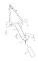
- the present invention is provided with a folder 14 which is attached to the main frame tube 13 located in between head tube 11 and stem 12 of the frame 10, where the folder 14 enables the main frame tube 13 to be folded, shown in FIGS. 2 & 3 .
- the first segment of the main frame tube 130, the portion of the main frame tube 130 between the folder 14 and the stem 12, is longer than the second segment of the main frame tube 131, the portion between the folder 14 and the head tube 11. This enables the first segment of the main frame tube 130 to accommodate the battery 20 (shown in FIGS. 6 ), where its outer diameter is fitted well with the inner diameter of the main frame tube 13, provided that the folder 14 is open (shown in FIGS. 4 & 5 ).
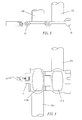
- the battery is being tightly mounted in the first segment of the main frame tube 130 and the battery 20 is further barricaded fixedly by a locking pin 15.
- the control system 30 (for instance a printed circuit control board) is placed in the second segment of the main frame tube 131 for a mount through the tube opening 1310. Since the battery 20 and the control system 30 are hided in the main frame tube 13, the overall looks wouldn't be influenced.
- the battery 20 is placed in the first segment of the main frame tube 130 and is close to 5-way pipe 16 which nears the attachment of the motor and the gears that enables the power cord 21 of the battery 20 goes through the shortest distance to connect the motor through the first segment of the main frame tube 130;
- the control system 30 is placed in the second segment of the main frame tube 131, and the power cord 31 of the control system 30 goes through the shortest distance to connect the control unit at the handle through the head tube 11, which simplifies the power control wiring and hides all in the tube.
- the present invention is provided with a folder 14 attached to the main frame tube 13, which enables the battery 20 and the control system 30 to be placed in the main frame tube 13 that makes them mounted in a complete hiding.
- the power control wiring is the minimum connected to the motor and the control unit, which substantially boosts the handiness of the wiring and the elegance of the looks, and is no doubt useful and creative than the prior art.
Landscapes
- Engineering & Computer Science (AREA)
- Chemical & Material Sciences (AREA)
- Combustion & Propulsion (AREA)
- Mechanical Engineering (AREA)
- Transportation (AREA)
- Battery Mounting, Suspending (AREA)
Abstract
Description
- The present invention generally relates to bike battery and control system mounting structures and more particularly relates to a main frame tube located between head tube and stem, having a folder attached to the main frame tube which enables the tube to be folded, where the battery and the control system can be placed into the tube from the tube openings at folding location, and the battery and the control system are mounted therein out of sight.
- Bikes are now provided with electric apparatus. Aside from the demand for a motor to drive the gears, a battery is set up to offer electric power to the motor, and a control system is needed to connect the motor and a control unit at the handle. As regards the mount of prior art batteries and control systems, some are fixed to the bike frame and covered by a shield, while others are placed into the frame tubes, where the tube ends are made deliberately downward, followed by a plastic plug for sealing. Among the above approaches of mounting the battery and the control system, the former protrudes from the bike frame which may debase the looks, and the latter has the frame tube end made downward deliberately which may restrict the overall interconnection of tubes and thus affect the rigidity of the bike frame.
In the light of the aforementioned drawbacks of the mount of the prior art batteries and the control systems, this inventor conceived the idea for the advanced improvement, and eventually the endeavors gave birth to this invention. - The objective of the present invention is to provide a bike battery and control system mounting structure where the battery and the control system are mounted in concealment adequately.
The main traits of the present invention lie in: the main frame tube is provided with a folder in between the head tube and the stem, which enables the frame tube to be folded, where the battery and the control system can be placed into the tube from the tube opening at folding location, and the battery and the control system are mounted therein out of sight. -
FIG. 1 is a front elevation of the structure of the exemplified embodiment of the present invention; -
FIG. 2 is a front elevation of the folded structure of the exemplified embodiment of the present invention; -
FIG. 3 is a partially enlarged view ofFIG. 1 ; -
FIG. 4 is a front elevation of the open state of the folder of the exemplified embodiment of the present invention; -
FIG. 5 is a top view of the open state of the folder of the exemplified embodiment of the present invention; and -
FIG. 6 is a sectional view of A-A ofFIG. 1 . - To achieve the foregoing objects and function of the present invention, the techniques and structure adopted are described with reference to the following preferred embodiment and the accompanying drawings.
- Referring to
FIGS. 1 &2 , the present invention is provided with afolder 14 which is attached to themain frame tube 13 located in betweenhead tube 11 andstem 12 of theframe 10, where thefolder 14 enables themain frame tube 13 to be folded, shown inFIGS. 2 &3 . The first segment of themain frame tube 130, the portion of themain frame tube 130 between thefolder 14 and thestem 12, is longer than the second segment of themain frame tube 131, the portion between thefolder 14 and thehead tube 11. This enables the first segment of themain frame tube 130 to accommodate the battery 20 (shown inFIGS. 6 ), where its outer diameter is fitted well with the inner diameter of themain frame tube 13, provided that thefolder 14 is open (shown inFIGS. 4 & 5 ). The battery is being tightly mounted in the first segment of themain frame tube 130 and thebattery 20 is further barricaded fixedly by alocking pin 15. The control system 30 (for instance a printed circuit control board) is placed in the second segment of themain frame tube 131 for a mount through thetube opening 1310. Since thebattery 20 and thecontrol system 30 are hided in themain frame tube 13, the overall looks wouldn't be influenced. Moreover, thebattery 20 is placed in the first segment of themain frame tube 130 and is close to 5-way pipe 16 which nears the attachment of the motor and the gears that enables thepower cord 21 of thebattery 20 goes through the shortest distance to connect the motor through the first segment of themain frame tube 130; thecontrol system 30 is placed in the second segment of themain frame tube 131, and thepower cord 31 of thecontrol system 30 goes through the shortest distance to connect the control unit at the handle through thehead tube 11, which simplifies the power control wiring and hides all in the tube. - From aforementioned description, the present invention is provided with a
folder 14 attached to themain frame tube 13, which enables thebattery 20 and thecontrol system 30 to be placed in themain frame tube 13 that makes them mounted in a complete hiding. Furthermore, the power control wiring is the minimum connected to the motor and the control unit, which substantially boosts the handiness of the wiring and the elegance of the looks, and is no doubt useful and creative than the prior art. - To sum up, the present invention is construed as not only novel but useful and creative, thereby filing the present application herein subject to the patent law.
Claims (4)
- A bike battery and control system mounting structure, featuring:a main frame tube located between head tube and stem, having a folder attached to the main frame tube which enables the tube to be folded, where the battery and the control system can be placed into the main frame tube from the tube opening at folding location, and the battery and the control system are mounted therein out of sight.
- A bike battery and control system mounting structure as in claim 1 wherein the first segment of the main frame tube, the portion of the main frame tube between the folder and the stem, is longer than the second segment of the main frame tube, the portion of the main frame tube between the folder and the head tube, which enables the first segment of the main frame tube to accommodate the battery from the first tube opening; the control system is placed in the second segment of the main frame tube for a mount through the second tube opening.
- A bike battery and control system mounting structure as in claim 1 wherein the outer diameter of the battery is fitted well with the inner diameter of the main frame tube, which enables the battery to be tightly mounted in the first segment of the main frame tube and the battery is further barricaded fixedly by a locking pin.
- A bike battery and control system mounting structure as in claim 2 wherein the outer diameter of the battery is fitted well with the inner diameter of the main frame tube, which enables the battery to be tightly mounted in the first segment of the main frame tube and the battery is further barricaded fixedly by a locking pin.
Priority Applications (1)
| Application Number | Priority Date | Filing Date | Title |
|---|---|---|---|
| EP09150297A EP2206643A1 (en) | 2009-01-09 | 2009-01-09 | Bike battery and control system mounting structure |
Applications Claiming Priority (1)
| Application Number | Priority Date | Filing Date | Title |
|---|---|---|---|
| EP09150297A EP2206643A1 (en) | 2009-01-09 | 2009-01-09 | Bike battery and control system mounting structure |
Publications (1)
| Publication Number | Publication Date |
|---|---|
| EP2206643A1 true EP2206643A1 (en) | 2010-07-14 |
Family
ID=40651646
Family Applications (1)
| Application Number | Title | Priority Date | Filing Date |
|---|---|---|---|
| EP09150297A Withdrawn EP2206643A1 (en) | 2009-01-09 | 2009-01-09 | Bike battery and control system mounting structure |
Country Status (1)
| Country | Link |
|---|---|
| EP (1) | EP2206643A1 (en) |
Cited By (2)
| Publication number | Priority date | Publication date | Assignee | Title |
|---|---|---|---|---|
| WO2019037323A1 (en) * | 2017-08-25 | 2019-02-28 | 金萍 | Connecting structure of electric vehicle frame and controller |
| CN109866626A (en) * | 2019-04-01 | 2019-06-11 | 南通天缘自动车有限公司 | It is a kind of for placing the materials in the tube of electric machine controller |
Citations (2)
| Publication number | Priority date | Publication date | Assignee | Title |
|---|---|---|---|---|
| EP0741441A2 (en) * | 1995-04-28 | 1996-11-06 | Yamaha Hatsudoki Kabushiki Kaisha | A charging device for a battery |
| EP0905014A2 (en) * | 1997-09-30 | 1999-03-31 | Honda Giken Kogyo Kabushiki Kaisha | Battery storing device of motor-assisted bicycle |
-
2009
- 2009-01-09 EP EP09150297A patent/EP2206643A1/en not_active Withdrawn
Patent Citations (2)
| Publication number | Priority date | Publication date | Assignee | Title |
|---|---|---|---|---|
| EP0741441A2 (en) * | 1995-04-28 | 1996-11-06 | Yamaha Hatsudoki Kabushiki Kaisha | A charging device for a battery |
| EP0905014A2 (en) * | 1997-09-30 | 1999-03-31 | Honda Giken Kogyo Kabushiki Kaisha | Battery storing device of motor-assisted bicycle |
Cited By (2)
| Publication number | Priority date | Publication date | Assignee | Title |
|---|---|---|---|---|
| WO2019037323A1 (en) * | 2017-08-25 | 2019-02-28 | 金萍 | Connecting structure of electric vehicle frame and controller |
| CN109866626A (en) * | 2019-04-01 | 2019-06-11 | 南通天缘自动车有限公司 | It is a kind of for placing the materials in the tube of electric machine controller |
Similar Documents
| Publication | Publication Date | Title |
|---|---|---|
| US20100175939A1 (en) | Bike battery and control system mounting structure | |
| CN103444013B (en) | Connector | |
| JP2014053091A (en) | Power incoming side connector for charging electric vehicle | |
| KR20160083076A (en) | Slide seat wire harness routing device | |
| EP2658045B1 (en) | Connector fixing structure | |
| EP2206643A1 (en) | Bike battery and control system mounting structure | |
| JP5752395B2 (en) | Operation unit | |
| CN201927769U (en) | Inner frame part assembly with safety pipe plug | |
| CN204334757U (en) | A kind of wire structures based on the equipment of taking photo by plane | |
| CN105452064B (en) | Power supply wire wiring structure to electric heating line terminals | |
| GB2380439A (en) | A holding device for an electric tool machine. | |
| EP1973203A3 (en) | Electrical connector having lever with protective shroud | |
| CN104787224A (en) | Assembly structure of mid-motor system and hanging bracket | |
| CN208576514U (en) | Harness mounting bracket and vehicle | |
| CN102606971A (en) | Atmospheric lamp holder assembly of automobile door panel | |
| JP2015208080A (en) | charging device | |
| CN207579780U (en) | A kind of improved tailstock camera | |
| EP2381047B1 (en) | Tubular skylight lamp | |
| CN201517759U (en) | LED lamp tube electrode | |
| CN202889838U (en) | Installation structure of wiring harness of controller | |
| CN108134473A (en) | A kind of motor cable fixing mechanism | |
| CN218021982U (en) | Hidden battery pack and electric carrier comprising same | |
| JP4949954B2 (en) | Harness wiring structure of power feeding device | |
| CN212673154U (en) | Telescopic conductive connection assembly | |
| CN212289649U (en) | Connection structure and headlight device |
Legal Events
| Date | Code | Title | Description |
|---|---|---|---|
| PUAI | Public reference made under article 153(3) epc to a published international application that has entered the european phase |
Free format text: ORIGINAL CODE: 0009012 |
|
| 17P | Request for examination filed |
Effective date: 20100326 |
|
| AK | Designated contracting states |
Kind code of ref document: A1 Designated state(s): AT BE BG CH CY CZ DE DK EE ES FI FR GB GR HR HU IE IS IT LI LT LU LV MC MK MT NL NO PL PT RO SE SI SK TR |
|
| AX | Request for extension of the european patent |
Extension state: AL BA RS |
|
| 17Q | First examination report despatched |
Effective date: 20101223 |
|
| STAA | Information on the status of an ep patent application or granted ep patent |
Free format text: STATUS: THE APPLICATION HAS BEEN WITHDRAWN |
|
| AKX | Designation fees paid |
Designated state(s): AT BE BG CH CY CZ DE DK EE ES FI FR GB GR HR HU IE IS IT LI LT LU LV MC MK MT NL NO PL PT RO SE SI SK TR |
|
| 18W | Application withdrawn |
Effective date: 20110303 |