EP0741265A2 - Akustisch pulsierender Brenner mit vollständig nachstellbaren, thermoakustischen Sondhauss-Elementen - Google Patents
Akustisch pulsierender Brenner mit vollständig nachstellbaren, thermoakustischen Sondhauss-Elementen Download PDFInfo
- Publication number
- EP0741265A2 EP0741265A2 EP96302040A EP96302040A EP0741265A2 EP 0741265 A2 EP0741265 A2 EP 0741265A2 EP 96302040 A EP96302040 A EP 96302040A EP 96302040 A EP96302040 A EP 96302040A EP 0741265 A2 EP0741265 A2 EP 0741265A2
- Authority
- EP
- European Patent Office
- Prior art keywords
- tube
- thermoacoustic
- burner assembly
- outer tube
- burner
- Prior art date
- Legal status (The legal status is an assumption and is not a legal conclusion. Google has not performed a legal analysis and makes no representation as to the accuracy of the status listed.)
- Granted
Links
Images

Classifications
-
- F—MECHANICAL ENGINEERING; LIGHTING; HEATING; WEAPONS; BLASTING
- F23—COMBUSTION APPARATUS; COMBUSTION PROCESSES
- F23C—METHODS OR APPARATUS FOR COMBUSTION USING FLUID FUEL OR SOLID FUEL SUSPENDED IN A CARRIER GAS OR AIR
- F23C15/00—Apparatus in which combustion takes place in pulses influenced by acoustic resonance in a gas mass
-
- F—MECHANICAL ENGINEERING; LIGHTING; HEATING; WEAPONS; BLASTING
- F23—COMBUSTION APPARATUS; COMBUSTION PROCESSES
- F23C—METHODS OR APPARATUS FOR COMBUSTION USING FLUID FUEL OR SOLID FUEL SUSPENDED IN A CARRIER GAS OR AIR
- F23C7/00—Combustion apparatus characterised by arrangements for air supply
-
- F—MECHANICAL ENGINEERING; LIGHTING; HEATING; WEAPONS; BLASTING
- F23—COMBUSTION APPARATUS; COMBUSTION PROCESSES
- F23C—METHODS OR APPARATUS FOR COMBUSTION USING FLUID FUEL OR SOLID FUEL SUSPENDED IN A CARRIER GAS OR AIR
- F23C99/00—Subject-matter not provided for in other groups of this subclass
- F23C99/003—Combustion process using sound or vibrations
Definitions
- This invention pertains to acoustic pulse producing burners adapted for burning gas, liquid or particulate fuels for utility and industrial usage. It particularly pertains to such burners in which acoustic pulsations are self-induced by integral axially moveable Sondhauss thermoacoustic type elements to facilitate complete combustion of the fuel.
- Zinn et al discloses a similar improved tunable pulse combustor adapted for moisture removal and particle heating, and including a combustion chamber with an axially translatable acoustic decoupling and flame holder configurations and utilizing axial translation of a flame holder within the combustor.
- the present invention provides an acoustically pulsating burner, for which acoustic pulsations are generated inside at least one thermoacoustic element located within the burner to facilitate combustion of gas, liquid or particulate fuels supplied through the burner.
- the burner assembly includes an elongated outer tube, a fuel supply means located within the outer tube, and at least one thermoacoustic element located within the outer tube.
- thermoacoustic element consists of an elongated tube having a closed forward warm end facing a combustion furnace, and an open cool end located away from the furnace.
- These Sondhauss thermoacoustic type element(s) are located within the elongated outer tube and in an air stream to the furnace, and their position within the burner is axially adjustable.
- the axial position of the thermoacoustic element(s) within the burner structure determines the temperature gradient along the length of the Sondhauss tubular element which drives the pulsations. This temperature differential governs the intensity of the acoustic pulsations, and the axial position of the Sondhauss element(s) will determine the magnitude of the pulsations.
- thermoacoustic element(s) When the thermoacoustic element(s) is moved away from the furnace, the temperature differential along the tube is reduced and no vibrations occur. By moving the thermoacoustic element(s) towards the furnace, the temperature differential increases and vibrations will start when the temperature differential between the hot and the cold sections of the Sondhauss tube reaches a critical value. Further movement of the element(s) towards the hot furnace will increase the intensity of the oscillations.
- the ratio of absolute temperature between the hot forward and cooler rear ends of the thermoacoustic tube should be in the range of 2-3/1.
- the thermoacoustic element(s) are slidably supported within the burner by suitable bearings, and the positioning of the thermoacoustic element(s) can be achieved by means of a hydraulic or mechanical mechanism controlled from outside the burner.
- the frequency of the sound generated will be constant for one particular length L of the tube element.
- Tubes of different lengths can be used for generating pulses of different frequencies in a burner assembly.
- the burner arrangement can be such that pulsations of one frequency will be generated (utilizing one or more thermoacoustic elements of the same length), or a multiple frequency pulsations can result from a simultaneous use of multiple thermoacoustic elements having different tube lengths.
- thermoacoustic element(s) can be either located on or near the burner longitudinal axis (one element), or located symmetrically about the burner axis (two or more elements) within the elongated outer tube.
- the ultimate location and configuration of the termoacoustic elements in a burner unit is determined by the location of the fuel supply nozzles and by the desired strength and frequency, if the acoustic pulsations, with larger size burners utilising more thermoacoustic elements.
- thermoacoustic element or the fuel nozzle can be located on the burner centerline, and either the thermoacoustic elements or the fuel supply nozzles can be placed in a symmetrical pattern about the burner centerline within an elongated outer tube.
- thermoacoustic element and one fuel nozzle can be provided in the elongated outer tube in an assymetric arrangement about the burner centerline.
- the closed end will extend slightly past the forward end of the outer tube, and in the retracted position the element is withdrawn rearwardly a distance equal to about 0 ⁇ .5 of the burner throat diameter.
- fuels such as coal and gas, coal and oil, or gas and oil
- an appropriate combination of the above arrangements with larger size burners utilizing more thermoacoustic elements can be utilized.
- the Sondhauss tube pulsations are driven by the sharp temperature differential between the warm air or gas existing at the closed forward end of the tube element, and the cooler air or gas in the remaining rearward portion of the tube.
- An additional aspect of this invention is to provide and control the sharp temperature differential in the element by means of an adjustable sleeve or liner located along a rear portion of the tube, which sleeve or liner acts as a thermal barrier against the heat coming from the furnace.
- the invention advantageously provides a burner assembly which is relatively simple in its construction and operation, and thermally efficient in its operation for combustion of various fuels, including gas, oil, and particulate fuels such as coal, and combinations thereof.
- the outer tube which encloses the thermoacoustic element(s) and the air/fuel supply tubes can have an outside diameter of 150 ⁇ -750 ⁇ mm and be 2,0 ⁇ 0 ⁇ 0 ⁇ -3,50 ⁇ 0 ⁇ mm long, although larger or smaller sizes could be used, and with the outer tube being aligned with a furnace throat opening having diameter of 20 ⁇ 0 ⁇ -1,0 ⁇ 0 ⁇ 0 ⁇ mm.
- the thermoacoustic element(s) are usually 50 ⁇ -80 ⁇ mm diameter and 60 ⁇ 0 ⁇ -950 ⁇ mm long, however, smaller and larger sizes could be used.
- the burner parts are usually made of an alloy steel or ceramic materials suitable for extended high temperature operations.
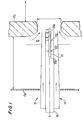
- an acoustic pulsating burner unit 10 ⁇ is provided and mounted in a windbox 12 of a furnace 17.
- the burner unit 10 ⁇ includes an outer elongated tube 14 through which primary air and pulverized coal fuel are conveyed through a throat opening 15 into the furnace 17. Secondary air at 13 enters throat opening 15 from the windbox 12 having rear wall 12a.
- the outer tube 14 surrounds an inner concentric tube 16 adapted for flow of tertiary air into the furnace 17.
- thermoacoustic element 20 ⁇ there is provided within the burner unit central inner tube 16 an elongated Sondhauss thermoacoustic element 20 ⁇ , which is closed at its forward end 20 ⁇ a and open at is rearward end 20 ⁇ b.
- the thermoacoustic element 20 ⁇ is supported and made axially adjustable within the central tube 16 by suitable multiple bearing means 22, such as sleeve or anti-friction type bearings.
- suitable multiple bearing means 22 such as sleeve or anti-friction type bearings.
- thermoacoustic tube 20 ⁇ When element 20 ⁇ is in a retracted position B no pulsations occur, and when element 20 ⁇ is in a forward position C within central tube 16 strong pulsations occur in the burner. These pulsations or vibrations within the thermoacoustic tube 20 ⁇ are driven by sharp temperature differences which exist between the warmer gas in the closed forward end of the tube and the cooler gas in the open rear end of the tube element 20. Such axial positioning of the thermoacoustic element 20 within inner tube 16 can be accomplished by suitable pneumatic or mechanical means (not shown).
- the burner unit 10 ⁇ is centrally located within the windbox 12 and throat opening 15 of the furnace 17 by suitable support means (not shown) attached to the furnace windbox and furnace outer wall 17a.
- the burner outer 14 tube can have 150 ⁇ -750 ⁇ mm diameter by up to 3,50 ⁇ 0 ⁇ mm long, and the thermoacoustic element can be 50 ⁇ -80 ⁇ mm diameter by 80 ⁇ 0 ⁇ -1,0 ⁇ 0 ⁇ 0 ⁇ mm long, however, smaller or larger sizes could be used.
- the air/coal velocity within tube 16 can be 15-50 ⁇ meter/sec.
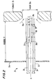
- an alternative acoustic pulsating burner unit 30 ⁇ is provided and mounted in a windbox 31 of a furnace 37.
- the burner unit 30 ⁇ includes an elongated outer tube 32 which is centrally located and suitably supported within the windbox 31 having rear wall 31a.
- Within outer tube 32 one or more gas supply tubes 34 are provided, which supply fuel for combustion.
- Primary air is provided through the outer tube 32 through passage at 33, and secondary air is supplied at 33a through throat opening 35 into the furnace 37.
- thermoacoustic element 36 which is closed at its forward end 36a, and open at its rearward end 36b, and is supported and made axially adjustable within the central outer tube 32.
- thermoacoustic tube element 36 When the thermoacoustic tube element 36 is in a central normal position A, normal acoustically induced pulsations occur within the tube which enhance the fuel mixing and combustion process. But when element 36 is in a retracted position B no pulsations occur, and when element 36 is in a forward position C within outer tube 32 strong acoustic pulsations occur. Similarly as for the Fig. 1 embodiment, these pulsations are driven by sharp temperature differences between the hot gas in the forward closed end of the tube and the cooler gas in the open rear end of the tube element 36.
- thermoacoustic element 36 is supported within the outer tube 32 and adjacent the gas supply tube(s) 34 by suitable bearing means 38, such as sleeve or roller type bearings.
- suitable bearing means 38 such as sleeve or roller type bearings.
- the axial positioning of element 36 can be accomplished by suitable hydraulic or mechanical means (not shown).
- one thermoacoustic element 36 and one or more gas supply tube(s) 34 can be mounted assymetrically within the outer tube 32.
- the burner outer tube 32 can have 150 ⁇ -750 ⁇ mm outside diameter and be 2,0 ⁇ 0 ⁇ 0 ⁇ -3,0 ⁇ 0 ⁇ 0 ⁇ mm long, while the thermoacoustic element 36 can be 50 ⁇ -70 ⁇ mm diameter and 750 ⁇ -950 ⁇ mm long, however, smaller or larger sizes could also be used.
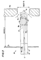
- Fig. 3 shows an alternative burner unit 40 ⁇ which is arranged to be suitable for combustion of oil fuel.
- the burner unit 40 ⁇ which is mounted within a furnace windbox 41, includes an elongated outer tube 42.
- an inner tube 43 provides fuel such as oil to a nozzle 44 provided at the tube forward end and within a throat opening 45 of the furnace wall 45a.
- at least one axially moveable Sondhauss thermoacoustic element 46 is provided within outer tube 42.
- the inner fuel supply tube 43 is preferably surrounded by two and up to eight Sondhauss thermoacoustic elements 46a, 46b, etc., spaced circumferentially around the centerline of burner 40 ⁇ .
- thermoacoustic element(s) 46 are supported within the outer tube 42 by suitable support means 48, and are made axially movable from a normal central position A in which normal pulsations occur, to a retracted position B in which no pulsations occur, or to a forward position C in which strong pulsations occur, as was explained above for the Fig. 1 and 2 embodiments.
- Primary air flow is provided at 47 within the outer tube 42, and secondary air flow is provided at 47a from windbox 41 through the furnace throat 45.
- the burner outer tube 42 can have a diameter of 150 ⁇ -750 ⁇ mm and length of 2,0 ⁇ 0 ⁇ 0 ⁇ -3,0 ⁇ 0 ⁇ 0 ⁇ mm, and the thermoacoustic elements 46 can have diameter of 50 ⁇ -70 ⁇ mm and length of 750 ⁇ -950 ⁇ mm.
- Fig. 4 shows a burner unit 50 ⁇ which is suitable for combustion of either gas or oil fuels.
- This burner unit which is provided within a windbox 51, includes an elongated outer stationary tube 52, and has a slideable closure member 53 provided at the tube inlet end to regulate primary air flow through the tube 52.
- a fuel nozzle 55 located at its forward end.
- fuel supply tube 54 is accompanies by at least one, and up to eight Sondhauss thermoacoustic elements 56a, 56b, etc. which can be spaced circumferentially around the burner centerline. These thermoacoustic elements 56a, 56b, etc.
- the element(s) 56 are suitably supported within the outer tube 52 by bearing support means 58, such as sleeve or anti-friction type bearings.
- the element(s) 56 are made axially movable from a normal central position A in which normal acoustic pulsations occur, to a retracted position B in which no pulsations occur, or to a forward position C in which strong pulsations occur.
- These elements 56 are surrounded by multiple air swirler vanes 59 attached to the elongated outer tube 52 or tube 54 or nozzle 55. Air flow from the furnace windbox 51 passes through the closure device 53 and vanes 59 into the furnace 57.
- An alternate burner arrangement from that shown in Fig. 4 can utilize air swirler vanes 59 having a smaller diameter, thereby permitting axial air flow through a passage way located around the swirler within the central tube 52.
- an air passage around tube 52 at the furnace wall can be provided, thereby connecting directly the windbox 51 with the furnace 57.
- Control of the sharp temperature differences and acoustic pulsation in the Sondhauss thermoacoustic element(s) of this invention may also be achieved or augmented by means of an axially adjustable outer sleeve provided near the element rear open end, as generally shown by Fig. 5.
- Thermoacoustic tube element 60 ⁇ includes a forward warm end 60 ⁇ a and a cooler rear end 60 ⁇ b. Surrounding the cool rear end portion 60 ⁇ b is an axially moveable outer sleeve 62, which has narrow annular space 61 provided therebetween.
- thermoacoustic element 60 ⁇ can be additionally controlled by a cool air or gas stream provided at 64, which serves to increase the temperature difference between the forward hot and rear cool end sections of the tube element 60 ⁇ .
- the sleeve 62 can contain a plurality of orifices 63 located along its length for escape of the cooling air or gas 64.
- Sleeve 62 is made axially moveable relative to tube 60 ⁇ by suitable mechanical means (not shown).
- thermoacoustic tube 70 ⁇ includes forward hot end 70 ⁇ a and cooler rear end 70 ⁇ b.
- an axially adjustable inner liner 72 which has a narrow annular space 71 provided between it and the tube 70 ⁇ .
- the thermoacoustic pulsations can be additionally controlled by providing a cool air or gas stream 74 through the annular space 71.
- the liner 72 can contain a plurality of orifices 73, as shown in an enlarged scale at Fig. 6A, and through which the cooling air or gas can exit into the tube 70 ⁇ .
- the rear portion of thermoacoustic tube 70 can contain a plurality of orifices 75 through which the cooling gas can exit from the tube 70 ⁇ .
- the sleeve 72 is made axially moveable by suitable mechanical means (not shown).
- An acoustically pulsating burner assembly is constructed similarly as shown in Fig. 1, having an elongated outer tube, an elongated inner tube, and a single Sondhauss thermoacoustic element centrally located on the longitudinal axis of the burner.
- This burner assembly is installed adjacent to a throat opening into a combustion furnace. Pulverized coal is conveyed by primary air flow through the burner for combustion in the furnace, such as for providing heat for generating pressurized steam.
- Important dimensional and operational characteristics of the burner are as follows: Furnace throat diameter, mm 1,10 ⁇ 0 ⁇ Outer tube length, mm 3,50 ⁇ 0 ⁇ Outer tube diameter, mm 750 ⁇ Inner tube diameter, mm 375 Thermoacoustic element length, mm 920 ⁇ Thermoacoustic element diameter, mm 75 Primary air velocity, m/s 15-50 ⁇ Secondary air/coal velocity, m/s 30 ⁇ -60 ⁇ Furnace combustion temperature, °C 1,70 ⁇ 0 ⁇ Ratio of absolute temperatures between the hot and the cooler section of the thermoacoustic element(s) 2.5 Axial movement of thermoacoustic element, mm 60 ⁇ 0 ⁇
Landscapes
- Engineering & Computer Science (AREA)
- Chemical & Material Sciences (AREA)
- Combustion & Propulsion (AREA)
- Mechanical Engineering (AREA)
- General Engineering & Computer Science (AREA)
- Fluidized-Bed Combustion And Resonant Combustion (AREA)
Applications Claiming Priority (2)
| Application Number | Priority Date | Filing Date | Title |
|---|---|---|---|
| US434893 | 1982-10-18 | ||
| US08/434,893 US5582515A (en) | 1995-05-04 | 1995-05-04 | Acoustically pulsating burner with integral adjustable Sondhauss thermoacoustic elements |
Publications (3)
| Publication Number | Publication Date |
|---|---|
| EP0741265A2 true EP0741265A2 (de) | 1996-11-06 |
| EP0741265A3 EP0741265A3 (de) | 1997-06-18 |
| EP0741265B1 EP0741265B1 (de) | 2001-09-05 |
Family
ID=23726134
Family Applications (1)
| Application Number | Title | Priority Date | Filing Date |
|---|---|---|---|
| EP96302040A Expired - Lifetime EP0741265B1 (de) | 1995-05-04 | 1996-03-25 | Akustisch pulsierender Brenner mit vollständig nachstellbaren, thermoakustischen Sondhauss-Elementen |
Country Status (7)
| Country | Link |
|---|---|
| US (1) | US5582515A (de) |
| EP (1) | EP0741265B1 (de) |
| JP (1) | JP2732246B2 (de) |
| CN (1) | CN1111669C (de) |
| CA (1) | CA2172342C (de) |
| DE (1) | DE69614913T2 (de) |
| ES (1) | ES2160209T3 (de) |
Cited By (2)
| Publication number | Priority date | Publication date | Assignee | Title |
|---|---|---|---|---|
| RU2184906C1 (ru) * | 2001-01-03 | 2002-07-10 | Закрытое акционерное общество "Экономия при газификации" | Теплогенератор для импульсного горения |
| WO2015090278A1 (de) * | 2013-12-18 | 2015-06-25 | Karlsruher Institut für Technologie | Pulsationsbrenner zur verbrennung fester brennstoffe und verfahren zu dessen betrieb |
Families Citing this family (8)
| Publication number | Priority date | Publication date | Assignee | Title |
|---|---|---|---|---|
| US6029956A (en) * | 1998-02-06 | 2000-02-29 | Foster Wheeler Usa Corporation | Predominantly liquid filled vapor-liquid chemical reactor |
| US20030157451A1 (en) * | 2001-12-13 | 2003-08-21 | Mccabe Michael I. | Low NOx particulate fuel burner |
| US7635264B2 (en) * | 2007-12-20 | 2009-12-22 | 3M Innovative Properties Company | Attenuating combustion noise of premixed flames |
| US20100192874A1 (en) * | 2009-01-30 | 2010-08-05 | Hughes Dennis R | Pulse combustion system for a water heater |
| WO2016010512A1 (en) * | 2014-07-14 | 2016-01-21 | Westinghouse Electric Company Llc | Thermo-acoustic nuclear power distribution measurement assembly |
| EP3104078A1 (de) * | 2015-06-12 | 2016-12-14 | IFTA Ingenieurbüro Für Thermoakustik GmbH | Thermoakustisches vorläuferverfahren und vorrichtung |
| CN105782963B (zh) * | 2016-03-02 | 2018-06-22 | 青岛物华万通节能科技有限公司 | 一种抗干扰能力强的脉动燃烧装置 |
| CN107859995B (zh) * | 2017-12-08 | 2024-03-12 | 山西大学 | 一种用于燃煤锅炉的Rijke型脉动燃烧系统 |
Family Cites Families (9)
| Publication number | Priority date | Publication date | Assignee | Title |
|---|---|---|---|---|
| SU1084315A1 (ru) * | 1982-12-29 | 1984-04-07 | Московский Ордена Трудового Красного Знамени Вечерний Металлургический Институт | Термическа печь |
| US4770626A (en) * | 1986-03-06 | 1988-09-13 | Sonotech, Inc. | Tunable pulse combustor |
| US5015171A (en) * | 1986-03-06 | 1991-05-14 | Sonotech, Inc. | Tunable pulse combustor |
| US5118281A (en) * | 1989-03-17 | 1992-06-02 | The United States Of America As Represented By The United States Department Of Energy | Method and apparatus for the control of fluid dynamic mixing in pulse combustors |
| US5209656A (en) * | 1991-08-29 | 1993-05-11 | Praxair Technology, Inc. | Combustion system for high velocity gas injection |
| US5266025A (en) * | 1992-05-27 | 1993-11-30 | Praxair Technology, Inc. | Composite lance |
| US5267850A (en) * | 1992-06-04 | 1993-12-07 | Praxair Technology, Inc. | Fuel jet burner |
| US5266024A (en) * | 1992-09-28 | 1993-11-30 | Praxair Technology, Inc. | Thermal nozzle combustion method |
| US5349813A (en) * | 1992-11-09 | 1994-09-27 | Foster Wheeler Energy Corporation | Vibration of systems comprised of hot and cold components |
-
1995
- 1995-05-04 US US08/434,893 patent/US5582515A/en not_active Expired - Fee Related
-
1996
- 1996-03-21 CA CA002172342A patent/CA2172342C/en not_active Expired - Fee Related
- 1996-03-25 EP EP96302040A patent/EP0741265B1/de not_active Expired - Lifetime
- 1996-03-25 ES ES96302040T patent/ES2160209T3/es not_active Expired - Lifetime
- 1996-03-25 DE DE69614913T patent/DE69614913T2/de not_active Expired - Fee Related
- 1996-05-06 CN CN96104945.6A patent/CN1111669C/zh not_active Expired - Fee Related
- 1996-05-07 JP JP8112335A patent/JP2732246B2/ja not_active Expired - Fee Related
Cited By (2)
| Publication number | Priority date | Publication date | Assignee | Title |
|---|---|---|---|---|
| RU2184906C1 (ru) * | 2001-01-03 | 2002-07-10 | Закрытое акционерное общество "Экономия при газификации" | Теплогенератор для импульсного горения |
| WO2015090278A1 (de) * | 2013-12-18 | 2015-06-25 | Karlsruher Institut für Technologie | Pulsationsbrenner zur verbrennung fester brennstoffe und verfahren zu dessen betrieb |
Also Published As
| Publication number | Publication date |
|---|---|
| DE69614913T2 (de) | 2002-01-17 |
| MX9601449A (es) | 1997-07-31 |
| ES2160209T3 (es) | 2001-11-01 |
| CN1111669C (zh) | 2003-06-18 |
| CN1145466A (zh) | 1997-03-19 |
| DE69614913D1 (de) | 2001-10-11 |
| CA2172342A1 (en) | 1996-11-05 |
| US5582515A (en) | 1996-12-10 |
| JPH08303719A (ja) | 1996-11-22 |
| EP0741265A3 (de) | 1997-06-18 |
| JP2732246B2 (ja) | 1998-03-25 |
| EP0741265B1 (de) | 2001-09-05 |
| CA2172342C (en) | 2007-05-15 |
Similar Documents
| Publication | Publication Date | Title |
|---|---|---|
| JP2588355B2 (ja) | オキシ・燃料燃焼装置 | |
| CA1110857A (en) | Dual fluid fuel nozzle | |
| US4443182A (en) | Burner and method | |
| US5123835A (en) | Pulse combustor with controllable oscillations | |
| EP0741265A2 (de) | Akustisch pulsierender Brenner mit vollständig nachstellbaren, thermoakustischen Sondhauss-Elementen | |
| DE3567531D1 (en) | Industrial burner for gaseous or liquid fuels | |
| US3275057A (en) | Tunnel burners | |
| CA1159353A (en) | Recuperative burners | |
| EP0003900A2 (de) | Gasbrenner mit an der Ziegeloberfläche haftender Flamme | |
| US4125360A (en) | Steam atomizing burner | |
| US4085708A (en) | Steam boilers | |
| EP0328418A1 (de) | Strahlrohrbeheizter Ofen und Brennstoffverbrennungsverfahren | |
| US6176702B1 (en) | Simple remotely tuned solid core fuel jet, low NOx fuel gas burner | |
| EP1321713A3 (de) | Flammrohr oder Bekleidung für die Brennkammer einer Gasturbine mit niedriger Schadstoffemission | |
| WO1998049496A1 (en) | An apparatus for cooling a combuster, and a method of same | |
| US4883003A (en) | Secondary combustion chamber for an incinerator | |
| EP1726877A1 (de) | Verfahren und vorrichtung zur regelung der primär- und sekundärlufteinspritzung einer müllverbrennungsanlage | |
| US4128065A (en) | General purpose incinerator/combustor | |
| JPH0237206A (ja) | バーナー | |
| US5322026A (en) | Waste combustion chamber with tertiary burning zone | |
| RU2660592C1 (ru) | Горелочная голова горелочного устройства | |
| US20150099232A1 (en) | Low NOx Burner with Low Pressure Drop | |
| US2609040A (en) | Combustion apparatus using compressed air | |
| RU2117867C1 (ru) | Горелка | |
| MXPA96001449A (en) | Acoustically pulsating burner with integral adjustable sondhauss thermoacoustic elements |
Legal Events
| Date | Code | Title | Description |
|---|---|---|---|
| PUAI | Public reference made under article 153(3) epc to a published international application that has entered the european phase |
Free format text: ORIGINAL CODE: 0009012 |
|
| AK | Designated contracting states |
Kind code of ref document: A2 Designated state(s): DE ES FR GB IT |
|
| PUAL | Search report despatched |
Free format text: ORIGINAL CODE: 0009013 |
|
| AK | Designated contracting states |
Kind code of ref document: A3 Designated state(s): DE ES FR GB IT |
|
| 17P | Request for examination filed |
Effective date: 19971215 |
|
| 17Q | First examination report despatched |
Effective date: 19991115 |
|
| GRAG | Despatch of communication of intention to grant |
Free format text: ORIGINAL CODE: EPIDOS AGRA |
|
| GRAG | Despatch of communication of intention to grant |
Free format text: ORIGINAL CODE: EPIDOS AGRA |
|
| GRAH | Despatch of communication of intention to grant a patent |
Free format text: ORIGINAL CODE: EPIDOS IGRA |
|
| GRAH | Despatch of communication of intention to grant a patent |
Free format text: ORIGINAL CODE: EPIDOS IGRA |
|
| GRAA | (expected) grant |
Free format text: ORIGINAL CODE: 0009210 |
|
| AK | Designated contracting states |
Kind code of ref document: B1 Designated state(s): DE ES FR GB IT |
|
| REF | Corresponds to: |
Ref document number: 69614913 Country of ref document: DE Date of ref document: 20011011 |
|
| REG | Reference to a national code |
Ref country code: ES Ref legal event code: FG2A Ref document number: 2160209 Country of ref document: ES Kind code of ref document: T3 |
|
| ET | Fr: translation filed | ||
| REG | Reference to a national code |
Ref country code: GB Ref legal event code: IF02 |
|
| PLBE | No opposition filed within time limit |
Free format text: ORIGINAL CODE: 0009261 |
|
| STAA | Information on the status of an ep patent application or granted ep patent |
Free format text: STATUS: NO OPPOSITION FILED WITHIN TIME LIMIT |
|
| 26N | No opposition filed | ||
| PGFP | Annual fee paid to national office [announced via postgrant information from national office to epo] |
Ref country code: IT Payment date: 20060331 Year of fee payment: 11 |
|
| PGFP | Annual fee paid to national office [announced via postgrant information from national office to epo] |
Ref country code: GB Payment date: 20070214 Year of fee payment: 12 |
|
| PGFP | Annual fee paid to national office [announced via postgrant information from national office to epo] |
Ref country code: DE Payment date: 20070226 Year of fee payment: 12 |
|
| PGFP | Annual fee paid to national office [announced via postgrant information from national office to epo] |
Ref country code: ES Payment date: 20070307 Year of fee payment: 12 |
|
| PGFP | Annual fee paid to national office [announced via postgrant information from national office to epo] |
Ref country code: FR Payment date: 20070212 Year of fee payment: 12 |
|
| GBPC | Gb: european patent ceased through non-payment of renewal fee |
Effective date: 20080325 |
|
| REG | Reference to a national code |
Ref country code: FR Ref legal event code: ST Effective date: 20081125 |
|
| PG25 | Lapsed in a contracting state [announced via postgrant information from national office to epo] |
Ref country code: DE Free format text: LAPSE BECAUSE OF NON-PAYMENT OF DUE FEES Effective date: 20081001 |
|
| PG25 | Lapsed in a contracting state [announced via postgrant information from national office to epo] |
Ref country code: FR Free format text: LAPSE BECAUSE OF NON-PAYMENT OF DUE FEES Effective date: 20080331 |
|
| REG | Reference to a national code |
Ref country code: ES Ref legal event code: FD2A Effective date: 20080326 |
|
| PG25 | Lapsed in a contracting state [announced via postgrant information from national office to epo] |
Ref country code: GB Free format text: LAPSE BECAUSE OF NON-PAYMENT OF DUE FEES Effective date: 20080325 |
|
| PG25 | Lapsed in a contracting state [announced via postgrant information from national office to epo] |
Ref country code: ES Free format text: LAPSE BECAUSE OF NON-PAYMENT OF DUE FEES Effective date: 20080326 |
|
| PG25 | Lapsed in a contracting state [announced via postgrant information from national office to epo] |
Ref country code: IT Free format text: LAPSE BECAUSE OF NON-PAYMENT OF DUE FEES Effective date: 20070325 |