EP0740950A2 - Sedimentation basin, especially for circulating systems - Google Patents
Sedimentation basin, especially for circulating systems Download PDFInfo
- Publication number
- EP0740950A2 EP0740950A2 EP96890075A EP96890075A EP0740950A2 EP 0740950 A2 EP0740950 A2 EP 0740950A2 EP 96890075 A EP96890075 A EP 96890075A EP 96890075 A EP96890075 A EP 96890075A EP 0740950 A2 EP0740950 A2 EP 0740950A2
- Authority
- EP
- European Patent Office
- Prior art keywords
- basin
- guide device
- section
- liquid
- opening
- Prior art date
- Legal status (The legal status is an assumption and is not a legal conclusion. Google has not performed a legal analysis and makes no representation as to the accuracy of the status listed.)
- Withdrawn
Links
Images

Classifications
-
- B—PERFORMING OPERATIONS; TRANSPORTING
- B01—PHYSICAL OR CHEMICAL PROCESSES OR APPARATUS IN GENERAL
- B01D—SEPARATION
- B01D21/00—Separation of suspended solid particles from liquids by sedimentation
- B01D21/02—Settling tanks with single outlets for the separated liquid
-
- B—PERFORMING OPERATIONS; TRANSPORTING
- B01—PHYSICAL OR CHEMICAL PROCESSES OR APPARATUS IN GENERAL
- B01D—SEPARATION
- B01D21/00—Separation of suspended solid particles from liquids by sedimentation
- B01D21/0039—Settling tanks provided with contact surfaces, e.g. baffles, particles
- B01D21/0042—Baffles or guide plates
-
- B—PERFORMING OPERATIONS; TRANSPORTING
- B01—PHYSICAL OR CHEMICAL PROCESSES OR APPARATUS IN GENERAL
- B01D—SEPARATION
- B01D21/00—Separation of suspended solid particles from liquids by sedimentation
- B01D21/24—Feed or discharge mechanisms for settling tanks
- B01D21/2405—Feed mechanisms for settling tanks
-
- B—PERFORMING OPERATIONS; TRANSPORTING
- B01—PHYSICAL OR CHEMICAL PROCESSES OR APPARATUS IN GENERAL
- B01D—SEPARATION
- B01D21/00—Separation of suspended solid particles from liquids by sedimentation
- B01D21/24—Feed or discharge mechanisms for settling tanks
- B01D21/2427—The feed or discharge opening located at a distant position from the side walls
-
- B—PERFORMING OPERATIONS; TRANSPORTING
- B01—PHYSICAL OR CHEMICAL PROCESSES OR APPARATUS IN GENERAL
- B01D—SEPARATION
- B01D21/00—Separation of suspended solid particles from liquids by sedimentation
- B01D21/24—Feed or discharge mechanisms for settling tanks
- B01D21/245—Discharge mechanisms for the sediments
Definitions
- the invention relates to a sedimentation basin, especially for circulatory systems according to the preamble of claim 1.
- Sedimentation basins are used in many areas of industry to separate contaminants from liquids.
- a water circuit for periodic cleaning of the precipitation surfaces is provided in wet electrostatic precipitators, the contaminants rinsed out of the filter having to be removed from the wash water before it is used further.
- this can take place by sedimentation in a tank provided for this purpose.
- the object of the present invention is to develop a sedimentation basin for water circulation systems which allows optimal separation of the particles contained in the liquid and, as a result, largely prevents their entrainment when the liquid is drawn out of the basin into the circuit while avoiding the disadvantages mentioned above.
- the sedimentation basin which is open at the top, can be placed directly in a cleaning system, where the liquid to be cleaned passes into the sedimentation basin via this opening. This eliminates any collection funnels and feed lines to the sedimentation basin.
- the sedimentation of particles is significantly improved by the even supply of the contaminated liquid from above through an opening that occupies the entire top surface of the basin. Between the guide device and the basin wall there is an area with clean liquid, which can be removed from there for return to the circuit without particles that are currently in the sedimentation phase being entrained when being drawn off.
- the above-mentioned effect is further improved by a funnel-shaped design of the guide device and a significantly better, almost complete separation of the contaminated, introduced liquid inside the guide device from the liquid cleaned by sedimentation outside the guide device is achieved.
- the guide device consists of an upper section which tapers conically downwards and, if need be, of an section thereon subsequent lower section with a substantially constant cross-section or smaller opening angle than that of the upper section, the opening angle of the upper section of the guide device being greater than that of the basin.
- the guiding device can consist of an essentially horizontal upper section and, if need be, an adjoining lower section with an essentially constant cross section or smaller opening angle than that of the upper section.
- At least one introduction opening in the upper section of the guide device is connected via a pipe section to the circulatory system located outside the basin, so that the contaminated liquid can be introduced into the basin without risk of contamination of the liquid already cleaned by the sedimentation.
- At least one introduction opening which defines the height of the liquid surface opens into the upper section of the guide device below the level of the overflow opening and the lowest discharge opening for the liquid lies above the lower end of the lower section of the guide device. This ensures that the liquid is continuously introduced below the liquid level in normal operation with the least possible disturbance of the sedimentation caused by the liquid introduction, for example due to liquid falling onto the liquid level.
- the axis of the or each discharge opening from the basin is oriented essentially tangentially to the wall of the basin, the plane of the discharge opening preferably being oriented substantially perpendicularly and radially to the vertical axis of the basin and the discharge opening opening in the same direction of rotation as the or each introduction.
- the particles that are possibly also transported along by the circular flow outside the guide device are thus carried past the discharge openings and are only carried along to a small extent by the liquid drawn off against the flow direction.
- the or each discharge line has a nozzle protruding into the basin with a discharge opening, thereby preventing liquid from being sucked in directly from the basin wall on which dropping particles.
- This nozzle is advantageously arranged at the greatest possible distance from the pool wall.
- a further improvement of the effect described above is possible if at least one liquid supply line is provided with a section oriented tangentially to the wall of the basin. With this construction, a flow tangential to the pool wall can be generated, which prevents the deposition of particles in the area of the pool wall and at the same time drives these particles away from the or each discharge opening.
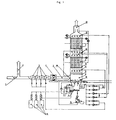
- the dust-laden exhaust gas is conveyed via a feed line 1 with an emergency chimney 2, at most after passing through at least one quench stage 3, with the aid of a fan 4 into a separation system 5.
- the separating plant 5 has the shape of a vertical tower, in which two electrostatic filter stages 6, 7 are arranged one above the other. Below the lower electrostatic filter 6 there is an equalization chamber 8, the upper limit of which is formed by a gas distributor plate 9. The lower limit of the equalization chamber 8 is formed by the liquid level 10 of the water in the sedimentation basin 11.
- lines 12 are provided with injection nozzles which are preferably directed towards the electrostatic filters 6, 7 or the gas distributor plate 9.
- the clean gas flow is conducted into the open via an opening forming the chimney 13.
- the electrostatic precipitators 6, 7 and the gas distributor plate 9 are cleaned, substances entering the wash water settle in the sedimentation basin 11 and are discharged from there by means of, for example, a screw 14 or a sludge pump and in a suitable device 15, e.g. a decanter, drained and disposed of as sludge.
- the water is advantageously returned to the pool 11.
- Any additives are stored in dry form in storage containers 16 and, before being introduced into the water of the water circuit in the basin 11 of the separating system 5, mixed with water to form a sludge in a stirred tank 17 and mixed in this form with the water in the basin 11.
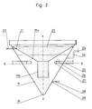
- FIG. 2 shows a longitudinal section of a preferred embodiment of the sedimentation basin 11 according to the invention on an enlarged scale.
- the basin 11 tapers conically downwards towards the bottom 18 in the form of an inverted truncated cone.
- Means 14 for discharging the settled sludge are provided on the bottom 18 or below it.
- a guide device 19 for the introduced liquid is mounted, which consists of two to one another subsequent sections 19a and 19b.
- the upper section 19a of the guide device 19 preferably tapers downward like the basin 11, but has a larger opening angle than the latter.
- the lower section 19b of the guide device 19 has a substantially constant cross section and ends above the bottom 18 of the basin 11.
- the lower section 19b of the guide device 19 ends essentially above this opening in the case of a discharge opening in the basin 11 for the sludge.
- a region is formed between the outside of the guide device 19 and the inside of the wall of the basin 11, which is also filled with liquid during normal operation of the system.
- an overflow line 24 opening at the level of the lower section 19b of the guide device 19 and its overflow opening 23, which determines the normal liquid level upwards, are used.
- the lowest liquid level during normal operation is defined by the lowest drain opening 27 for liquid from the basin 11 , which opens above the lower end of the guide device 19 or above its lower section 19b into the pool area between the guide device 19 and the pool wall.
- the discharge opening 27 is connected via line 25 to the liquid circuit of the separation system.
- the liquid from the circuit which is contaminated with the particles to be separated is brought either directly from above via an opening 20 which essentially occupies the entire top surface and / or via a line 22 through the basin 11 to the introduction opening 21 into the interior of the guide device.
- the insertion opening 21 is at a height above that of the overflow opening 23.
- the liquid level is at a height between the overflow opening 23 and the lowermost discharge opening 27.
- a circular flow in the basin 11 along its wall in the direction of the arrow S is generated by a ring line 28 with four inlets 29 oriented tangentially to the wall of the basin 11.
- the or each discharge opening 27 is provided at the front end of a connecting piece 26 projecting a little beyond the wall of the basin 11 and is oriented in the same sense as the liquid flow caused by the inlets 29, the entry of the liquid into the discharge openings 27 being essentially horizontal and tangential to the wall of the basin 11.
- the axis of the connecting piece 26 can be aligned radially to the axis A of the basin 11, as in FIG.
- a short curved end piece with the discharge opening 27 can be provided, so that the essentially tangential orientation of this opening is made possible.
- the spigot 26 can as in the embodiment of Fig. 3b also carried out essentially completely straight, but already provided tangentially to the axis A of the basin 11. The liquid flow in the direction of arrow S thus simultaneously prevents the deposition of sludge on the wall of the basin 11 and carries contaminants away from the discharge opening 27. This significantly reduces the risk of operational failures due to blockages or the like.
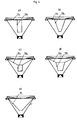
- FIGS. 4c and 4d show different design variants of the guide device 19 of the sedimentation basin.
- a substantially horizontal upper section 19a is followed by a lower section 19b with a substantially constant cross section up to the lower end.
- the lower section 19b tapers towards the bottom, but with a slightly smaller opening angle than that of the wall of the basin 11.
- FIGS. 4c and 4d are both characterized by a guide device 19 with a downwardly tapering upper section 19a.
- FIG. 4c this is followed by a lower section 19b with an essentially constant cross-section
- FIG. 4d an embodiment is shown with a likewise tapering lower section 19b.
- the upper section 19a of the guide device 19 in the basin 11 has a larger opening angle than the wall thereof, while the lower section 19b has a smaller opening angle than the basin 11 itself.
- the embodiment of FIG. 4e is finally equipped with a guide device 19 which tapers continuously from its upper end to its lower end and which has no transition between an upper and lower section.
- the opening angle of the funnel-shaped guide device 19 from FIG. 4e is larger than that of the wall of the basin 11.
Abstract
Description
Die Erfindung betrifft ein Sedimentationsbecken, speziell für Kreislaufsysteme nach dem Oberbegriff des Anspruchs 1.The invention relates to a sedimentation basin, especially for circulatory systems according to the preamble of claim 1.
In vielen Bereichen der Industrie werden Sedimentationsbecken zur Abscheidung von Verunreinigungen aus Flüssigkeiten eingesetzt. Beispielsweise ist in Naßelektrofiltern ein Wasserkreislauf zur periodischen Abreinigung der Niederschlagsflächen vorgesehen, wobei aus dem Waschwasser vor dessen weiterer Verwendung die aus dem Filter ausgespülten Verunreinigungen entfernt werden müssen. Dies kann für partikelförmige Substanzen, die nicht in Lösung gehen, durch Sedimentation in einem dafür vorgesehenen Becken stattfinden.Sedimentation basins are used in many areas of industry to separate contaminants from liquids. For example, a water circuit for periodic cleaning of the precipitation surfaces is provided in wet electrostatic precipitators, the contaminants rinsed out of the filter having to be removed from the wash water before it is used further. For particulate substances that do not go into solution, this can take place by sedimentation in a tank provided for this purpose.
Die Aufgabe der vorliegenden Erfindung besteht in der Entwicklung eines Sedimentationsbeckens für Wasserkreislaufsysteme, welches eine optimale Abscheidung der in der Flüssigkeit enthaltenen Partikel gestattet und in weiterer Folge deren Mitreißen beim Abziehen der Flüssigkeit aus dem Becken in den Kreislauf weitestgehend verhindert unter Vermeidung der oben erwähnten Nachteile.The object of the present invention is to develop a sedimentation basin for water circulation systems which allows optimal separation of the particles contained in the liquid and, as a result, largely prevents their entrainment when the liquid is drawn out of the basin into the circuit while avoiding the disadvantages mentioned above.
Diese Aufgabe wird erfindungsgemäß durch das im kennzeichnenden Teil des Anspruchs 1 angegebene Merkmal gelöst. Das oben offene Sedimentationsbecken kann direkt in eine Reinigungsanlage eingebracht werden, wo die zu reinigende Flüssigkeit über diese Öffnung in das Sedimentationsbecken gelangt. Dadurch entfallen allfällige Sammeltrichter und Zuleitungen zum Sedimentationsbecken. Die Sedimentation von Partikeln wird durch die gleichmäßige Zuführung der verunreinigten Flüssigkeit von oben über eine die gesamte Deckfläche des Beckens einnehmenden Öffnung bedeutend verbessert. Zwischen der Leiteinrichtung und der Beckenwand entsteht ein Bereich mit sauberer Flüssigkeit, welche von dort zur Rückführung in den Kreislauf entnommen werden kann, ohne daß sich gerade in der Sedimentationsphase befindliche Partikel beim Abziehen mitgerissen werden.This object is achieved by the feature specified in the characterizing part of claim 1. The sedimentation basin, which is open at the top, can be placed directly in a cleaning system, where the liquid to be cleaned passes into the sedimentation basin via this opening. This eliminates any collection funnels and feed lines to the sedimentation basin. The sedimentation of particles is significantly improved by the even supply of the contaminated liquid from above through an opening that occupies the entire top surface of the basin. Between the guide device and the basin wall there is an area with clean liquid, which can be removed from there for return to the circuit without particles that are currently in the sedimentation phase being entrained when being drawn off.
Durch eine trichterförmige Ausführung der Leiteinrichtung wird der oben erwähnte Effekt noch weiter verbessert und eine bedeutend bessere, fast vollständige Trennung der verschmutzten, eingeleiteten Flüssigkeit innerhalb der Leiteinrichtung von der durch Sedimentation gereinigten Flüssigkeit außerhalb der Leiteinrichtung erzielt.The above-mentioned effect is further improved by a funnel-shaped design of the guide device and a significantly better, almost complete separation of the contaminated, introduced liquid inside the guide device from the liquid cleaned by sedimentation outside the guide device is achieved.
Gemäß einem weiteren Erfindungsmerkmal besteht die Leiteinrichtung aus einem oberen, sich nach unten konisch verjüngenden Abschnitt und allenfalls aus einem sich daran anschließenden unteren Abschnitt mit im wesentlichen konstanten Querschnitt bzw. geringerem Öffnungswinkel als jenem des oberen Abschnittes, wobei der Öffnungswinkel des oberen Abschnittes der Leiteinrichtung größer ist als jener des Beckens. Durch eine derartige Ausführungsform wird die Sedimentation noch weiter verbessert und der Reinwasserbereich des Beckens vergrößert, wodurch mehr Einbauraum für Abzugseinrichtungen od. dgl. aus dem Becken geschaffen wird.According to a further feature of the invention, the guide device consists of an upper section which tapers conically downwards and, if need be, of an section thereon subsequent lower section with a substantially constant cross-section or smaller opening angle than that of the upper section, the opening angle of the upper section of the guide device being greater than that of the basin. Such an embodiment further improves the sedimentation and increases the clean water area of the basin, as a result of which more installation space for extraction devices or the like is created from the basin.
Alternativ dazu kann unter Realisierung der selben Vorteile die Leiteinrichtung aus einem im wesentlichen horizontalen oberen Abschnitt und allenfalls einem sich daran anschließenden unteren Abschnitt mit im wesentlichen konstanten Querschnitt bzw. geringerem Öffnungswinkel als jenem des oberen Abschnittes bestehen.Alternatively, while realizing the same advantages, the guiding device can consist of an essentially horizontal upper section and, if need be, an adjoining lower section with an essentially constant cross section or smaller opening angle than that of the upper section.
Um eine vollständige Erfassung aller in das Becken eingebrachten, abzuscheidenden Verunreinigungen zu gewährleisten, sind alle Einbringöffnungen für die Flüssigkeit aus dem Kreislauf oberhalb und/oder innerhalb des Bereiches der Leiteinrichtung vorgesehen.In order to ensure complete detection of all contaminants introduced into the basin that are to be separated, all introduction openings for the liquid from the circuit are provided above and / or within the area of the guide device.
Vorteilhafterweise ist zumindest eine Einbringöffnung in den oberen Abschnitt der Leiteinrichtung über ein Rohrstück mit dem außerhalb des Beckens befindlichen Kreislaufsystem verbunden, sodaß die verunreinigte Flüssigkeit ohne Gefahr der Verschmutzung der bereits durch die Sedimentation gereinigten Flüssigkeit im Becken eingeleitet werden kann.Advantageously, at least one introduction opening in the upper section of the guide device is connected via a pipe section to the circulatory system located outside the basin, so that the contaminated liquid can be introduced into the basin without risk of contamination of the liquid already cleaned by the sedimentation.
Gemäß einem weiteren Erfindungsmerkmal mündet zumindest eine die Höhe der Flüssigkeitsoberfläche definierende Einbringöffnung in den oberen Abschnitt der Leiteinrichtung unterhalb des Niveaus der Überlauföffnung und liegt die unterste Abzugsöffnung für die Flüssigkeit oberhalb des unteren Endes des unteren Abschnittes der Leiteinrichtung. Dadurch wird eine im Normalbetrieb dauernd unterhalb des Flüssigkeitsspiegels stattfindende Flüssigkeitseinbringung mit geringstmöglicher Störung der Sedimentation durch die Flüssigkeitseinbringung, beispielsweise durch auf den Flüssigkeitsspiegel hinunterstürzende Flüssigkeit, gewährleistet.According to a further feature of the invention, at least one introduction opening which defines the height of the liquid surface opens into the upper section of the guide device below the level of the overflow opening and the lowest discharge opening for the liquid lies above the lower end of the lower section of the guide device. This ensures that the liquid is continuously introduced below the liquid level in normal operation with the least possible disturbance of the sedimentation caused by the liquid introduction, for example due to liquid falling onto the liquid level.
Wenn zumindest eine Abzugsleitung für die Flüssigkeit aus dem Becken im Raum zwischen der Wand des Beckens und der Leiteinrichtung, vorzugsweise in Höhe deren unteren Abschnittes in das Becken mündet, kann dadurch die Rückleitung von weitestgehend reiner Flüssigkeit ohne Gefahr des Mitreißens gerade absinkender Partikel sichergestellt werden. Da sich durch die Abwärtsbewegung der Flüssigkeit innerhalb der Leiteinrichtung, allenfalls noch durch diese bzw. die Orientierung der Einbringöffnungen für die Flüssigkeit in das Becken unterstützt, eine zirkuläre Strömung im Becken ausbilden kann, ist es vorteilhaft, wenn gemäß einem weiteren Erfindungsmerkmal die Achse der oder jeder Abzugsöffnung aus dem Becken im wesentlichen tangential zur Wand des Beckens orientiert ist, wobei vorzugsweise die Ebene der Abzugsöffnung im wesentlichen senkrecht und radial zur vertikalen Achse des Beckens orientiert und die Abzugsöffnung im selben Umlaufsinn wie die oder jede Einleitung mündet. Die von der zirkulären Strömung außerhalb der Leiteinrichtung allenfalls noch mittransportierten Partikel werden so an den Abzugsöffnungen vorbeigetragen und werden nur zu einem geringen Anteil von der entgegen der Strömungsrichtung abgezogenen Flüssigkeit mitgenommen.If at least one drain line for the liquid from the basin in the space between the wall of the basin and the guide device, preferably at the level of the lower Section opens into the basin, the return of largely pure liquid can be ensured without risk of entrainment of just sinking particles. Since a circular flow can form in the basin as a result of the downward movement of the liquid within the guide device, possibly supported by this or the orientation of the introduction openings for the liquid into the basin, it is advantageous if, according to a further feature of the invention, the axis of the or each discharge opening from the basin is oriented essentially tangentially to the wall of the basin, the plane of the discharge opening preferably being oriented substantially perpendicularly and radially to the vertical axis of the basin and the discharge opening opening in the same direction of rotation as the or each introduction. The particles that are possibly also transported along by the circular flow outside the guide device are thus carried past the discharge openings and are only carried along to a small extent by the liquid drawn off against the flow direction.
Der im vorigen Absatz genannte Vorteil kann noch weiter ausgebaut werden, wenn gemäß einem weiteren Merkmal der Erfindung die oder jede Abzugsleitung einen in das Becken hineinragenden Stutzen mit einer Abzugsöffnung aufweist, wodurch verhindert wird, daß Flüssigkeit direkt von der Beckenwand angesaugt wird, auf der sich herabsinkende Partikel abgelagert haben. Dieser Stutzen wird vorteilhafterweise in möglichst großem Abstand zur Beckenwand angeordnet.The advantage mentioned in the previous paragraph can be further expanded if, according to a further feature of the invention, the or each discharge line has a nozzle protruding into the basin with a discharge opening, thereby preventing liquid from being sucked in directly from the basin wall on which dropping particles. This nozzle is advantageously arranged at the greatest possible distance from the pool wall.
Eine weitere Verbesserung des oben beschriebenen Effekts ist möglich, wenn zumindest eine Flüssigkeitszuleitung mit einem tangential zur Wand des Beckens orientierten Abschnitt vorgesehen ist. Mit dieser Konstruktion kann eine zur Beckenwand tangentiale Strömung erzeugt werden, welche die Ablagerung von Partikeln im Bereich der Beckenwand verhindert und gleichzeitig diese Partikel von der oder jeder Abzugsöffnung wegtreibt.A further improvement of the effect described above is possible if at least one liquid supply line is provided with a section oriented tangentially to the wall of the basin. With this construction, a flow tangential to the pool wall can be generated, which prevents the deposition of particles in the area of the pool wall and at the same time drives these particles away from the or each discharge opening.
In der nachfolgenden Beschreibung wird die Erfindung anhand einer bevorzugten Ausführung unter Bezugnahme auf die beigefügten Zeichnungen näher beschrieben.In the following description, the invention is described in more detail using a preferred embodiment with reference to the accompanying drawings.
Es zeigen
- Fig. 1
- eine Schema einer Gesamtanlage zur Rohgasreinigung einschließlich aller Nebenanlagen und -aggregate und dem erfindungsgemäßen Sedimentationsbecken,
- Fig. 2
- einen Längsschnitt des erfindungsgemäßen Sedimentationsbeckens,
- Fig. 3a und 3b
- jeweils einen Querschnitt längs der Schnittlinie III-III aus Fig. 2 und
- Fig. 4a bis 4e
- schematisch verschiedene Ausführungsformen der Leiteinrichtung des Sedimentationsbeckens im Längsschnitt.
- Fig. 1
- a diagram of an overall system for raw gas purification including all secondary systems and aggregates and the sedimentation basin according to the invention,
- Fig. 2
- 2 shows a longitudinal section of the sedimentation basin according to the invention,
- 3a and 3b
- each have a cross section along the section line III-III from FIGS. 2 and
- 4a to 4e
- schematically different embodiments of the guide device of the sedimentation basin in longitudinal section.
Wie in Fig. 1 dargestellt, wird das staubbeladene Abgas über eine Zuleitung 1 mit einem Notkamin 2 allenfalls nach Passieren zumindest einer Quench-Stufe 3 mit Hilfe eines Ventilators 4 in eine Abscheideanlage 5 befördert. Die Abscheideanlage 5 hat die Form eines senkrechten Turmes, in welchem übereinander zwei Elektrofilterstufen 6, 7 angeordnet sind. Unterhalb des unteren Elektrofilters 6 befindet sich eine Vergleichmäßigungskammer 8, deren obere Begrenzung durch ein Gasverteilerblech 9 gebildet ist. Die untere Begrenzung der Vergleichmäßigungskammer 8 wird durch den Flüssigkeitsspiegel 10 des Wassers im Sedimentationsbecken 11 gebildet. Zur Abreinigung der Bauteile im Inneren der Abscheideanlage 5, speziell zur Abreinigung der Elektrofilter 6, 7 sind Leitungen 12 mit vorzugsweise auf die Elektrofilter 6, 7 bzw. das Gasverteilerblech 9 gerichteten Einspritzdüsen vorgesehen. Ober dem zweiten, oberen Elektrofilter 7 wird der Reingasstrom über eine, den Kamin 13 bildende Öffnung ins Freie geleitet. Bei der Abreinigung der Elektrofilter 6, 7 und des Gasverteilerbleches 9 in das Waschwasser gelangende Substanzen setzen sich im Sedimentationsbecken 11 auf dessen Boden ab und werden von dort mittels beispielsweise einer Schnecke 14 oder einer Schlammpumpe ausgetragen und in einer geeigneten Einrichtung 15, wie z.B. einem Dekanter, entwässert und als Schlamm entsorgt. Das Wasser wird vorteilhafterweise wieder dem Becken 11 rückgeführt. Allfällige Zusatzstoffe werden in trockener Form in Vorratsbehältem 16 gelagert und vor Einbringung in das Wasser des Wasserkreislaufes im Becken 11 der Abscheideanlage 5 in einem Rührbehälter 17 mit Wasser zu einem Schlamm vermischt und in dieser Form dem Wasser im Becken 11 zugemischt.As shown in FIG. 1, the dust-laden exhaust gas is conveyed via a feed line 1 with an emergency chimney 2, at most after passing through at least one quench stage 3, with the aid of a fan 4 into a separation system 5. The separating plant 5 has the shape of a vertical tower, in which two
In Fig. 2 ist in vergrößertem Maßstab ein Längsschnitt einer bevorzugten Ausführung des erfindungsgemäßen Sedimentationsbeckens 11 dargestellt. Das Becken 11 verjüngt sich konisch nach unten zum Boden 18 hin in Form eines umgekehrten Kegelstumpfes. Am Boden 18 oder unterhalb desselben sind Einrichtungen 14 zur Ausbringung des abgesetzten Schlamms vorgesehen. Innerhalb des Beckens 11 ist, vorzugsweise direkt an dessen oberem Rand beginnend und die gesamte darunterliegende Fläche des Beckens 11 abdeckend eine Leiteinrichtung 19 für die eingebrachte Flüssigkeit montiert, die aus zwei aneinander anschließenden Abschnitten 19a und 19b besteht. Der obere Abschnitt 19a der Leiteinrichtung 19 verjüngt sich vorzugsweise ebenso wie das Becken 11 konisch nach unten hin, weist aber gegenüber letzterem einen größeren Öffnungswinkel auf. Der untere Abschnitt 19b der Leiteinrichtung 19 weist im wesentlichen konstanten Querschnitt auf und endet oberhalb des Bodens 18 des Beckens 11. Vorzugsweise endet der untere Abschnitt 19b der Leiteinrichtung 19 im Falle einer Austragsöffnung im Becken 11 für den Schlamm im wesentlichen oberhalb dieser Öffnung. Zwischen der Außenseite der Leiteinrichtung 19 und der Innenseite der Wand des Beckens 11 wird ein Bereich gebildet, der bei Normalbetrieb der Anlage auch mit Flüssigkeit gefüllt ist. Zur Niveauregelung der Flüssigkeit im Becken dient eine in Höhe des unteren Abschnittes 19b der Leiteinrichtung 19 mündende Überlaufleitung 24 und deren das normale Flüssigkeitsniveau nach oben hin bestimmende Überlauföffnung 23. Das unterste Flüssigkeitsniveau bei Normalbetrieb wird durch die unterste Abzugsöffnung 27 für Flüssigkeit aus dem Becken 11 definiert, die oberhalb des unteren Endes der Leiteinrichtung 19 bzw. oberhalb von dessen unterem Abschnitt 19b in den Beckenbereich zwischen Leiteinrichtung 19 und Beckenwand mündet. Die Abzugsöffnung 27 steht über die Leitung 25 mit dem Flüssigkeitskreislauf der Abscheideanlage in Verbindung. Die mit den abzuscheidenden Partikeln verunreinigte Flüssigkeit aus dem Kreislauf wird entweder direkt von oben über eine im wesentlichen die gesamte Deckfläche einnehmende Öffnung 20 und/oder über eine Leitung 22 durch das Becken 11 zur Einbringöffnung 21 ins Innere der Leiteinrichtung gebracht. Die Einbringöffnung 21 liegt dabei in einer Höhe oberhalb jener der Überlauföffnung 23. Der Flüssigkeitsspiegel liegt in einer Höhe zwischen der Überlauföffnung 23 und der untersten Abzugsöffnung 27.2 shows a longitudinal section of a preferred embodiment of the
Wie in Fig. 3a und Fig. 3b durch strichlierte Darstellung erläutert ist, wird durch eine Ringleitung 28 mit vier tangential zur Wand des Beckens 11 ausgerichteten Einleitungen 29 eine zirkuläre Strömung im Becken 11 entlang von dessen Wand in Richtung des Pfeiles S erzeugt. Die oder jede Abzugsöffnung 27 ist am vorderen Ende eines ein Stück über die Wand des Beckens 11 hinausragenden Stutzens 26 vorgesehen und im selben Sinn wie die durch die Einleitungen 29 hervorgerufene Flüssigkeitsströmung orientiert, wobei der Eintritt der Flüssigkeit in die Abzugsöffnungen 27 im wesentlichen horizontal und tangential zur Wand des Beckens 11 erfolgt. Dabei kann die Achse der Stutzen 26 wie in Fig. 3a radial zur Achse A des Beckens 11 ausgerichtet und ein kurzes gekrümmtes Endstück mit der Abzugsöffnung 27 vorgesehen sein, damit die im wesentlichen tangentiale Orientierung dieser Öffnung ermöglicht ist. Andererseits können die Stutzen 26 wie in der Ausführungsform der Fig. 3b auch im wesentlichen völlig gerade ausgeführt aber selbst bereits tangential zur Achse A des Beckens 11 vorgesehen sein. Die Flüssigkeitsströmung im Sinn des Pfeiles S verhindert somit gleichzeitig die Ablagerung von Schlamm auf der Wand des Beckens 11 und trägt Verunreinigungen von den Abzugsöffnung 27 weg. Damit ist die Gefahr von Betriebsausfällen durch Verstopfungen od. dgl. deutlich vermindert. Durch die Leiteinrichtung 19 innerhalb des Beckens und die Anordnung aller Einbringöffnungen 20, 21 für die Flüssigkeit ober- oder innerhalb dieser Leiteinrichtung 19 und auf oder unter die Flüssigkeitsoberfläche sowie die Anordnung aller Abzugsöffnungen 27 zwischen der Außenseite der Leiteinrichtung 19 und Wand des Beckens 11 wird eine möglichst ungestörte Sedimentation zugleich mit der geringstmöglichen Gefahr des Mitreißens von sich gerade absetzenden oder gerade eingebrachten Partikeln gewährleistet. Auch allfällige Einbringöffnungen für Zusatzstoffe in das Kreislaufwasser können vorteilhafterweise oberhalb der Leiteinrichtung 19 vorgesehen sein, sodaß die Zusatzstoffe ohne Störung der Sedimentation zugegeben werden können. Durch eine Öffnung am Boden 18 des Beckens 11 werden die aussedimentierten Feststoffe allenfalls mit Hilfe einer Schnecke oder einer Schlammpumpe od. dgl. ausgetragen.As illustrated in FIGS. 3a and 3b by a broken line, a circular flow in the
In den Fig. 4a bis 4e sind verschiedene Ausführungsvarianten der Leiteinrichtung 19 des Sedimentationsbeckens dargestellt. In Fig. 4a schließt sich an einen im wesentlichen horizontalen oberen Abschnitt 19a ein unterer Abschnitt 19b mit im wesentlichen konstantem Querschnitt bis zum unteren Ende an. Bei der Variante der Fig. 4b verjüngt sich der untere Abschnitt 19b dagegen nach unten hin, jedoch mit einem etwas geringeren Öffnungswinkel als jenem der Wand des Beckens 11. Die Varianten der Fig. 4c und 4d sind beide gekennzeichnet durch eine Leiteinrichtung 19 mit einem sich nach unten hin verjüngenden oberen Abschnitt 19a. Im Fall der Fig. 4c schließt sich daran ein unterer Abschnitt 19b mit im wesentlichen konstantem Querschnitt an, während in Fig. 4d eine Ausführungsform mit sich ebenfalls verjüngendem unteren Abschnitt 19b dargestellt ist. In letzterem Fall hat der obere Abschnitt 19a der Leiteinrichtung 19 im Becken 11 einen größeren Öffnungswinkel als dessen Wandung, während der untere Abschnitt 19b einen geringeren Öffnungswinkel als das Becken 11 selbst aufweist. Die Ausführungsform der Fig. 4e ist schließlich mit einer Leiteinrichtung 19 ausgestattet, die sich stetig von seinem oberen bis hin zu seinem unteren Ende konisch verjüngt und der keinen Übergang zwischen einen oberen und unteren Abschnitt besitzt. Der Öffnungswinkel der trichterförmigen Leiteinrichtung 19 aus Fig. 4e ist größer als jener der Wandung des Beckens 11.4a to 4e show different design variants of the
Claims (11)
Applications Claiming Priority (2)
| Application Number | Priority Date | Filing Date | Title |
|---|---|---|---|
| AT748/95 | 1995-05-02 | ||
| AT0074895A AT402817B (en) | 1995-05-02 | 1995-05-02 | SEDIMENTATION BASIN, SPECIAL FOR CIRCUIT SYSTEMS |
Publications (2)
| Publication Number | Publication Date |
|---|---|
| EP0740950A2 true EP0740950A2 (en) | 1996-11-06 |
| EP0740950A3 EP0740950A3 (en) | 1997-03-05 |
Family
ID=3498772
Family Applications (1)
| Application Number | Title | Priority Date | Filing Date |
|---|---|---|---|
| EP96890075A Withdrawn EP0740950A3 (en) | 1995-05-02 | 1996-04-24 | Sedimentation basin, especially for circulating systems |
Country Status (2)
| Country | Link |
|---|---|
| EP (1) | EP0740950A3 (en) |
| AT (1) | AT402817B (en) |
Cited By (1)
| Publication number | Priority date | Publication date | Assignee | Title |
|---|---|---|---|---|
| CN105664544A (en) * | 2016-03-29 | 2016-06-15 | 中国恩菲工程技术有限公司 | Thickener |
Citations (6)
| Publication number | Priority date | Publication date | Assignee | Title |
|---|---|---|---|---|
| DE281131C (en) * | ||||
| US1919653A (en) * | 1931-11-27 | 1933-07-25 | Raymond A Hill | Hydraulic sand extractor |
| US3617544A (en) * | 1970-05-11 | 1971-11-02 | Sybron Corp | Hot process settling tank having adjustable downcomer |
| US4132643A (en) * | 1975-07-29 | 1979-01-02 | Hellqvist Ake O V | Sludge and slime separating and settling device |
| EP0585103A2 (en) * | 1992-08-24 | 1994-03-02 | Technology Finance Corporation (Proprietary) Limited | Process for treating a suspension of solid particles in a carrier liquid |
| DE29507254U1 (en) * | 1995-05-02 | 1995-06-29 | Scheuch Alois Gmbh | Sedimentation basin, especially for ice skating systems |
Family Cites Families (6)
| Publication number | Priority date | Publication date | Assignee | Title |
|---|---|---|---|---|
| AT364325B (en) * | 1979-07-27 | 1981-10-12 | Mueller Hansjoerg Dr | DEVICE FOR SEPARATING SOLIDS FROM LIQUIDS |
| CS239007B1 (en) * | 1983-07-04 | 1985-12-16 | Vladimir Mackrle | Method of nitrogen substances containing biological activation sewage treatment and equipment for application of this method |
| DE3428557A1 (en) * | 1984-08-02 | 1986-02-13 | Linde Ag, 6200 Wiesbaden | Apparatus for the biological purification of waste water |
| JPS643818A (en) * | 1987-06-25 | 1989-01-09 | Teac Corp | Optical recording and reproducing device |
| DE3812715A1 (en) * | 1988-04-16 | 1989-10-26 | Borsig Gmbh | Settling tank for activated sludge wastewater suspension |
| FI89703C (en) * | 1989-03-06 | 1993-11-10 | Wiser Oy | Device for the treatment of liquids, especially waste water |
-
1995
- 1995-05-02 AT AT0074895A patent/AT402817B/en not_active IP Right Cessation
-
1996
- 1996-04-24 EP EP96890075A patent/EP0740950A3/en not_active Withdrawn
Patent Citations (6)
| Publication number | Priority date | Publication date | Assignee | Title |
|---|---|---|---|---|
| DE281131C (en) * | ||||
| US1919653A (en) * | 1931-11-27 | 1933-07-25 | Raymond A Hill | Hydraulic sand extractor |
| US3617544A (en) * | 1970-05-11 | 1971-11-02 | Sybron Corp | Hot process settling tank having adjustable downcomer |
| US4132643A (en) * | 1975-07-29 | 1979-01-02 | Hellqvist Ake O V | Sludge and slime separating and settling device |
| EP0585103A2 (en) * | 1992-08-24 | 1994-03-02 | Technology Finance Corporation (Proprietary) Limited | Process for treating a suspension of solid particles in a carrier liquid |
| DE29507254U1 (en) * | 1995-05-02 | 1995-06-29 | Scheuch Alois Gmbh | Sedimentation basin, especially for ice skating systems |
Non-Patent Citations (1)
| Title |
|---|
| PATENT ABSTRACTS OF JAPAN Bd. 13, Nr. 227 (C-600) <3575> 25 Mai 1989 & JP-A-01 003 818 (CHIDORI KOSAN K.K.) 08 Februar 1989 * |
Cited By (1)
| Publication number | Priority date | Publication date | Assignee | Title |
|---|---|---|---|---|
| CN105664544A (en) * | 2016-03-29 | 2016-06-15 | 中国恩菲工程技术有限公司 | Thickener |
Also Published As
| Publication number | Publication date |
|---|---|
| EP0740950A3 (en) | 1997-03-05 |
| ATA74895A (en) | 1997-01-15 |
| AT402817B (en) | 1997-09-25 |
Similar Documents
| Publication | Publication Date | Title |
|---|---|---|
| DE2524544A1 (en) | DEVICE AND METHOD FOR TREATMENT OF GASES OR LIQUIDS CONTAMINATED BY SOLID PARTICLES | |
| EP0195826A1 (en) | Mixing, sedimentation device or the like for liquids containing particles | |
| DE3140997A1 (en) | DEVICE FOR SEPARATING FLUIDS AND SOLIDS | |
| DE1457299C3 (en) | Device for removing particles from a contaminated gaseous medium | |
| DE19953961B4 (en) | Device for separating suspended matter from wastewater | |
| DE4331415C2 (en) | Device for treating a gas stream with washing liquid | |
| DE2850690A1 (en) | METHOD AND DEVICES FOR CENTRIFUGAL TREATMENT OF FLUIDS OR GASES FOR SEPARATING IMPURITIES AT HIGH SPEED | |
| DE2512104C2 (en) | Cyclone for separating solids from liquids or gases | |
| EP3222357A1 (en) | Sludge separator | |
| DE60012329T2 (en) | IMPROVED INJECTION OF WATER LOADED WITH SOLID PARTICLES INTO A CENTRIFUGAL SEPARATOR | |
| DE102006020273B4 (en) | Apparatus and method for purifying wastewater | |
| DE2708135A1 (en) | Slurries separator for mining operations etc. - comprises basket shaped sieve with cyclonic entry and outer housing to draw=off liquor | |
| DE19850320C2 (en) | Compact system for the mechanical treatment of waste water | |
| EP1137469B1 (en) | Device for separating waste water | |
| EP0740950A2 (en) | Sedimentation basin, especially for circulating systems | |
| EP2893981B1 (en) | Sludge separator | |
| DE19521741C2 (en) | Flow separator with two stages for separating solid particles from a flowing liquid | |
| EP0965375B1 (en) | Device for removing solid matter from a mixture of liquid and solid matter | |
| DE4025465C1 (en) | Waste water rain catch basin - has circular funnel with sludge sump and tangential inlet flow | |
| AT780U1 (en) | SEDIMENTATION BASIN, SPECIAL FOR CIRCUIT SYSTEMS | |
| DE10200599B4 (en) | Device for separating organic and inorganic material from a liquid | |
| EP1134323A2 (en) | Sand trap device | |
| EP0508047A1 (en) | Purifier for waste water | |
| DE102017128560B3 (en) | Device for separating suspended matter from liquids, cleaning device and method for separating suspended matter | |
| EP3392206B1 (en) | Water raiser with a separating device |
Legal Events
| Date | Code | Title | Description |
|---|---|---|---|
| PUAI | Public reference made under article 153(3) epc to a published international application that has entered the european phase |
Free format text: ORIGINAL CODE: 0009012 |
|
| AK | Designated contracting states |
Kind code of ref document: A2 Designated state(s): AT BE DE ES FR GB IT |
|
| PUAL | Search report despatched |
Free format text: ORIGINAL CODE: 0009013 |
|
| AK | Designated contracting states |
Kind code of ref document: A3 Designated state(s): AT BE DE ES FR GB IT |
|
| 17P | Request for examination filed |
Effective date: 19970402 |
|
| RAP1 | Party data changed (applicant data changed or rights of an application transferred) |
Owner name: SCHEUCH GMBH |
|
| 17Q | First examination report despatched |
Effective date: 20010418 |
|
| STAA | Information on the status of an ep patent application or granted ep patent |
Free format text: STATUS: THE APPLICATION IS DEEMED TO BE WITHDRAWN |
|
| 18D | Application deemed to be withdrawn |
Effective date: 20010829 |