EP0740737B1 - Plasmasprengverfahren und vorrichtung - Google Patents
Plasmasprengverfahren und vorrichtung Download PDFInfo
- Publication number
- EP0740737B1 EP0740737B1 EP95910098A EP95910098A EP0740737B1 EP 0740737 B1 EP0740737 B1 EP 0740737B1 EP 95910098 A EP95910098 A EP 95910098A EP 95910098 A EP95910098 A EP 95910098A EP 0740737 B1 EP0740737 B1 EP 0740737B1
- Authority
- EP
- European Patent Office
- Prior art keywords
- explodable conductor
- plasma
- explodable
- conductor
- blasting
- Prior art date
- Legal status (The legal status is an assumption and is not a legal conclusion. Google has not performed a legal analysis and makes no representation as to the accuracy of the status listed.)
- Expired - Lifetime
Links
Images








Classifications
-
- E—FIXED CONSTRUCTIONS
- E21—EARTH OR ROCK DRILLING; MINING
- E21B—EARTH OR ROCK DRILLING; OBTAINING OIL, GAS, WATER, SOLUBLE OR MELTABLE MATERIALS OR A SLURRY OF MINERALS FROM WELLS
- E21B7/00—Special methods or apparatus for drilling
- E21B7/14—Drilling by use of heat, e.g. flame drilling
- E21B7/15—Drilling by use of heat, e.g. flame drilling of electrically generated heat
-
- E—FIXED CONSTRUCTIONS
- E21—EARTH OR ROCK DRILLING; MINING
- E21C—MINING OR QUARRYING
- E21C37/00—Other methods or devices for dislodging with or without loading
- E21C37/18—Other methods or devices for dislodging with or without loading by electricity
-
- F—MECHANICAL ENGINEERING; LIGHTING; HEATING; WEAPONS; BLASTING
- F42—AMMUNITION; BLASTING
- F42D—BLASTING
- F42D3/00—Particular applications of blasting techniques
Definitions
- the invention relates in general to an apparatus for plasma blasting comprising a driver for supplying pulsed high current to a probe to create a plasma for fracturing a geological formation by shock waves resulting from the plasma. More particularly, the invention relates to an apparatus wherein the driver has a capacitance for storing a large amount of electric charge at high voltage. An inductor of the driver carries the discharge current pulse from the capacitance and delivers it to an electrically matched removable explodable conductor coupled to the probe. The explodable conductor is positioned within a bore of the geological formation or other solid material.
- Exploding wire systems are exemplified by U.S. Patent No. 5,052,272 to Lee for Launching Projectiles With Hydrogen Gas Generated From Aluminum Fuel Powder/Water Reactions.
- Lee discloses a method of generating hydrogen gas with high energy efficiency by applying pulse power techniques to a trigger wire and an aluminum fuel powder-oxidizer mixture.
- the preferred oxidizer of the aluminum fuel powder is water.
- the apparatus includes a capacitor bank connected to an induction coil.
- a metal conductor wire is connected to the induction coil and a fast switch. When the switch is closed, electrical energy from the capacitor bank flows through the inductor and the switch as well as the wire.
- the total energy of the electrical discharge is preferably from 0.50 to 15 kilojoules per gram of aluminum fuel. The discharge lasts between 10 and 1000 microseconds.
- U.S. Patent No. 3,583,766 to Padberg, Jr. discloses a deep submergence search vehicle having a drill pipe into a bore formed in a layer of mineral deposits and extending into a sedimentary ocean bed.
- a drill head is positioned at the lower end of the drill pipe with a plasma discharge section positioned above the drill head.
- An energizing circuit couples electrical energy from a power source to a thin nickel wire extending through the plasma discharge section. When a switch is closed, a high current is suddenly passed through the thin nickel wire exploding it and creating a large plasma discharge accompanied by sharp pressure waves. Openings in the plasma discharge section allow the pressure waves to emerge and produce a rapidly expanding and collapsing gas bubble with accompanying shock waves simulating those of explosives. The alternate bubble expansion and collapse propagates acoustic waves in the form of sharp pressure pulses.
- Soviet Union No. SU 357345 A to Yutkin discloses a rock breaking device having a pair of electrodes and a conductive wire strip for insertion in a hole in rock filled with a wetted dielectric bulk material, such as sand, to produce shock waves when energized.
- the wire is connected to the electrodes and stretched around a dielectric plate.
- the dielectric plate is positioned in the rock hole for bursting operation.
- a capacitor or condenser bank charged to 6000 volts or more by the combination of high voltage rectifier and high voltage transformer.
- a capacitor bank may be charged to 6000 volts for working in soft earth and higher voltages of 30,000 volts or more for working in harder soil or rocky areas.
- a switch when a switch is closed an initial surge of voltage reaches the electrodes positioned in water. The resistance of the water is lowered as the water is converted to plasma by the electric current pulse. Rapid release of electrical energy across the resistance of the water plasma produces a large amount of heat to produce an explosive effect that impacts and thrusts aside the earth ahead of the electrode.
- U.S. Patent No. 4,741,405 to Moeny et al. discloses a spark discharge drill for subterranean mining.
- the drill may deliver pulses of energy ranging from several kilojoules up to 100 kilojoules or more to a rock face at the rate of 1 to 10 pulses per second or more.
- a drilling fluid such as mud or water assists propagation of spark energy to the rock face.
- U.S. Patent No. 4,897,577 to Kitzinger for Electromechanically Triggered Spark Gaps discloses an anode and a cathode having facing surfaces defining a gap.
- a trigger electrode is located in the vicinity of the gap.
- a piezoelectric generator connected between the trigger electrode and the cathode triggers the spark gap switch.
- the switch may handle currents on the order of 100,000 amperes or higher from a capacitor discharge circuit.
- U.S. Patent No. 5,106,164 to Kitzinger et al. is regarded as the closest prior art and represents the preamble features of independent claim 1 and discloses a plasma blasting process for fragmenting rock in the practice of hard rock mining. Electrical energy from a capacitor bank is switched to supply 500 kiloamperes to a blasting electrode positioned within a bore in a rock face causing dielectric breakdown of an electrolyte, preferably containing copper sulfate, to form a plasma.
- the electrolyte may be gelled with bentonite or gelatin to make it viscous enough so that it will not leak out of the confined area prior to blasting.
- the blasting apparatus has minimal inductance and resistance in order to reduce power loss and ensure rapid discharge of energy into the rock.
- One of the drawbacks of the prior art systems is that the energy transfer from the capacitance to the explodable conductor or spark gap is relatively inefficiently. As a result of the inefficient transfer of energy, it was necessary to provide relatively large capacitor banks for driving either the explodable conductor or the spark gap to provide a given amount of explosive energy.
- the spark gap systems also suffer from the drawback that the zone at which the energy is to be dissipated, that is the gap between the electrodes, initially has a high impedance followed by insulating breakdown at the gap due to the applied voltage with a relatively lower impedance plasma being formed. As a result, the change in gap impedance from high to low impedance does not dissipate energy at the gap as efficiently as an exploding wire system might.
- apparatus for plasma blasting a solid comprising capacitive means for storing electrical energy; an explodable conductor having a given length and cross-section and electrically coupled to said capacitive means to receive electric current, said electric current heating said explodable conductor from a solid to a plasma in proximity with a vaporizable working fluid to perform work on the solid; and switch means selectively coupling the electric charge potential from said capacitive means to said explodable conductor; characterized by inductive means coupled to said capacitive means to receive the flow of electric charge and slow the rate of change of the electric current to the explodable conductor, the increase in resistance of the explodable conductor occurring when it changes from solid to plasma causing current to the plasma to produce an increased voltage drop across the plasma with resulting increased dissipation of heat to the working fluid, the square root of the ratio of the inductance of the inductive means divided by the capacitance of the capacitance means being proportional to the ratio of the length of
- a method for plasma blasting a solid comprising the steps of charging a capacitance with an electric charge; and characterized by transferring the electric charge through an inductance to an explodable conductor, wherein the square root of the ratio of the inductance to the capacitance is proportional to a length of the explodable conductor divided by its cross-sectional area and the volume of the explodable conductor is proportional to the electrical energy stored in the capacitance.
- the present specification describes apparatus for plasma blasting having a driver circuit with a large multi-capacitor capacitor bank.
- the capacitor bank is connected to deliver current to a high current switch, such as an ignitron, controlled by a -trigger circuit connected to a grid of the ignitron.
- a distributed inductance of the drive circuit when taken in conjunction with the large capacitance of the capacitor bank, results in a circuit having a relatively significant reactive impedance with a relatively low dissipative or resistive impedance.
- the explodable conductor should have a volume, as defined by the product of the fuse length (l) and the fuse cross sectional area (A), that is proportional to the stored energy in the capacitor bank CV 2 and a length to cross sectional area ratio which is proportional to the square root of the inductance of the distributed inductance divided by the capacitance.
- the length (l) is measured in the direction of current flow.
- the desired energy transfer is enhanced by selecting the explodable conductor characteristics such that it has a tendency to explode when peak current is flowing through the fuse. At that point, a large amount of current is flowing, the resistance of the plasma across the fuse site has increased when the solid explodable conductor is converted to a plasma thereby causing the I 2 R drop at the explodable conductor site to increase even further. This enhances the localized energy dissipation at the fuse site with respect to energy dissipation in other portions of the circuit and further provides a good match for energy transfer to the fuse site.
- the instant invention also relates to a plasma fracturing system having an explodable conductor either in the form of a metal ribbon conductor wound as a helix or multiple helices around a mandrel or in the alternative a cup-shaped conductor.
- an explodable conductor either in the form of a metal ribbon conductor wound as a helix or multiple helices around a mandrel or in the alternative a cup-shaped conductor.
- Both the ribbon and cup type explodable conductors have relatively large surface area to volume ratios to provide rapid heat dissipation from the explodable conductor site to rapidly release mechanical energy thereby fracturing of surrounding rock.
- the desirable energy transfer characteristics from a relatively small capacitor bank can be further increased by placing a powdered metal and oxidant mixture in the immediate location of the explodable conductor.
- the preferred mixture is comprised of aluminum and water, although other powdered metals may be used. It has been found that the force of the explosion is considerably enhanced.
- the interchangeable nature of the explodable conductor allows the same probe to be reused for a number of shots with relatively low expense.
- the cost of the other portions of the apparatus is kept low as relatively small capacitance banks, as opposed to the prior art, can be employed and providing relatively smaller current flows through the cables into the probe and back out, thereby allowing conventional cabling networks to be used which reduces the cost of the apparatus.
- the apparatus for plasma blasting 10 includes a driver circuit for supplying pulsed high current, high voltage energy to a blasting probe 14 adapted to be placed in a rock formation.
- the probe 14 has removably electrically coupled to it a matched removable explodable conductor 16.
- a conventional high voltage supply 20 is connected thereto via a ground lead 22 and a lead 24.
- a lead 26 is coupled to capacitive or capacitance means 28 comprising a capacitor bank having capacitors 30, 32, 34, 36 and 38 for storing electrical energy.
- the total capacitance of the capacitor bank 28 is 4190 microfarads at a nominally peak rated voltage of 11,000 volts.
- a ground lead 40 connects the capacitance bank 28 also to a ground 42 to which the ground lead 22 is also connected.
- the high voltage supply 20 charges the capacitance bank 28 to a high potential, for instance 5 kilovolts or 10 kilovolts.
- the stored charge may then be released as a current pulse through other portions of the driver circuit 12 to the probe 14.
- the driver circuit 12 has a distributed resistance of 22 milliohms as exemplified by the distributive resistance symbol 44.
- the current pulse is produced by current flowing through the lead 26 and switch means comprising an ignitron 46 having a cathode 48, an anode 50 and a control electrode 52.
- the ignitron 46 selectively couples the electrical energy from the capacitor bank 28 to the explodable conductor 16. It controls the flow of current and is itself controlled by a trigger circuit 54 connected through a lead 56 to the trigger 52.
- the trigger electrode 54 supplies a potential to the ignitron trigger 52
- the current pulse flows through the ignitron 46 and through a lead 58 to the probe 14.
- Inductive means comprising a distributed inductance of 147 microhenries of the driver circuit 12 is represented by an inductor 60.
- the distributed inductance 60 receives the current and slows the rate of change of the current supplied to the explodable conductor 16.
- the slowed current pulse is supplied over the lead 58 which is coupled to a twisted pair 60 comprised of conventional 0000-gauge welding cable and having a first cable 62 and a second or grounded cable 64.
- Current flowing through the lead 58 to the cable 62 is sensed by a Rogowski coil 66 inductively coupled to the lead 58 for the measurement of the current flow through the lead 58 to the probe 14.
- Voltage across the probe 14 is effectively measured by a voltage measuring apparatus 70 connected between the cables 62 and 64.
- the cable 64 is grounded to the common ground 42 to provide a current return path to the capacitor bank 28.
- the electrical blasting probe 14 coaxial electrodes, having an overall length of 108.59 cm (42.75 inches).
- the bulk of an outer ground return conductor 71 comprises a cylindrical steel pipe 72 having a 7.303 cm (2.875 inch) outer diameter.
- a pair of ends 74 and 76 of the steel pipe 72 are threaded at portions 78 and 80, respectively, to be connected electrically to the driver circuit 12.
- an aluminum current spreading plate 82 is fastened with a brass spanner nut 84 threaded below the aluminum plate 82 and a brass spanner nut 86 threaded above the aluminum plate 82.
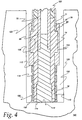
- An oversized 10.2 cm (four inch) long high voltage insulated stand-off 88 is positioned above the steel pipe 72 and the brass spanner nut 86, and a polyethylene flash shield 90 provides additional electrical insulation for a second aluminum current spreading plate 92 fastened between a spanner nut 94 and an acorn nut 96 connecting an inner tubular brass high voltage electrode 98, shown in cross section in FIG. 4.
- the flash shield 90 provides added insulation in the event that unexpectedly high voltages are generated as the exploding conductor 16 opens.
- The, twisted pair 60 is connected with conventional welding cable lugs 97 and 99 to the aluminum current spreading plates 82 and 92 by bolt-nut pairs 100 and 102, respectively, which provide means for receiving electrical current to deliver electrical energy to the blasting probe 14.
- An outer steel restrainer collar/ground electrode 104 is threaded to the bottom of the steel pipe 72. The ground electrode 104 makes electrical contact with the explodable conductor 16.
- the explodable conductor 16 is a metal ribbon wound as a helix on a mandrel 108, forming a fuse cartridge 110.
- the mandrel 108 is a 11.43 cm (4.5 inches) long cylindrical pipe comprised of PVC, however, any insulative material such as a Dixie (RTM) cup on which to wind the explodable conductor 16 will suffice.
- the ribbon explodable conductor 16 could be replaced by a metal cup.
- tubular brass high voltage electrode 98 extends from the top of the blasting probe 14 to the lower portion, where a steel high voltage electrode tip 112 is press-fit into the tubular brass high voltage electrode 98 to effect good electrical connection via a flexible circular copper sheet end piece 114 with the explodable conductor 16.
- a ground contact end 116 of the collar/ground electrode 104 provides electrical contact to the explodable conductor 16 for ground return.
- a G-10 fiberglass insulator 118 is disposed coaxially between the inner high voltage electrode and the outer ground return electrode.
- the G-10 fiberglass insulator 118 extends from the bottom end portion of the probe 14 up about 46 cm (about 18 inches), where a lap joint 120 provides an interface to a cylindrical Delrin acetal polymer insulator 122 extending coaxially within the cylindrical steel pipe 72 to an oversized high voltage standoff 124 at the top end of the blasting probe 14.
- the steel restrainer collar/ground electrode 104 provides a stepped shoulder region 126 where the G-10 fiberglass insulator 118 becomes wider and is thus mechanically captured by the steel restrainer collar/ground electrode 104.
- the capturing of the G-10 fiberglass insulator 118 at the bottom end of the blasting probe 14 and the use of the cylindrical acetal polymer insulator 122 at the top end of the blasting probe 14 joined at the lap joint 122 provides a coaxial insulator assembly which is able to survive the blast and be reusable.
- the widening of the blasting probe 14 at the end of the steel restrainer collar/ground electrode 104 defines a confined area within the drill hole 129 wherein an annulus or explodable conductor region 130 may contain the working fluid as described further below. Alternatively, the working fluid may be contained within the confined area of the explodable conductor 16.
- the steel high voltage electrode tip 112 extends a small distance from the G-10 fiberglass insulator 118.
- the mandrel 108 the explodable conductor 16 connected at an end 132 to the circular end piece 114.
- the explodable conductor 16 is positioned in electrical connection both with the ground contact end 116 and the steel high voltage electrode tip 112 that pushes outward against the circular end piece 114.
- the sheet circular end piece 114 closes off one end of a section of the mandrel 108 and is comprised of flexible copper sheet to assure good electrical contact at both ends of the explodable conductor 16.
- multiple explodable conductors 16' each comprise a metal ribbon that is helically wound about the mandrel 108 parallel with the other ribbons 16'.
- An assembly of two or more ribbons so configured was tested in Example V as set forth hereafter, which describes the use of four parallel ribbons 16' to encourage more intimate contact between explodable conductors 16' and a reactive working fluid.
- the explodable conductors 16 and 16' comprise various length strips of 0.14 mm (5.5 mil) thick aluminum foil which are folded lengthwise to a 1.91 cm (0.75 inch) resulting width.
- the electrical blasting probe 14 is emplaced in a 94 cm (37 inch) cube, high strength 68.9 MPa (10,000 psi) concrete test sample 140.
- Such concrete test samples were used in the examples III - VI set forth below.
- a dashed line 142 represents a conical fracture surface which one would expect to observe if cracks were launched uniformly outward from the stress-enhanced inside corner of the circular hole having walls which intersect at right angles as shown.
- Such "base cones” or “volcanoes” were invariably found among the pieces following a test. The most symmetric cones were obtained from the highest energy shots.
- the working fluid may be placed in the drill hole 129 at the annulus 130 to receive heat from the explodable conductor 16 to perform pressure-volume (pV) work for rock cracking. Since water is employed as a working fluid its also is a source of oxygen and acts as an oxidizer or oxidant for exothermic reactions with powdered metal such as aluminum that may be used to chemically augment the plasma fracturing of the rock.
- pV pressure-volume
- the lower end of the probe 14 extends approximately 48 cm (19 inches) into the concrete test sample and the hole 129 drilled therein has a diameter of 7.31 cm (2.88 inches), which is the bore produced by a standard rock drill.
- the overall diameter of the blasting probe 14 is 7.302 cm (2.875 inches) at the steel restrainer collar/ground electrode 40, slightly less than the hole diameter. The tight fit between the blasting probe 14 and the drill hole 129 prevents blow-by of the working fluid contained in the annular region of annulus 130 during an explosion.
- the annulus 130 is filled with a gelling agent such as Knox gelatine mixed with water and a fine suspended aluminum powder.
- a gelling agent such as Knox gelatine mixed with water and a fine suspended aluminum powder.
- other metal powders such as titanium or iron which exothermically react with water providing a rapidly expanding gas will alsc be an acceptable fuel in accordance with the invention.
- the released energy density of the chemical reaction of the aluminum-water mixture driven the exploding fuse amounts to approximately 10 kilojoules per cubic centimeter of mixture. At this energy density approximately 0.5 megajoules of energy is evolved per linear inch of the mandrel 108.
- the capacitor bank energy is approximately 10 percent of the total energy released. Chemical augmentation is desired when the energy requirement is high and eliminates the need for blasting with high explosives.
- the aluminum-water mixture functions as a fuel or energetic propellant. The energy is released via a local phenomenon in the vicinity of the fuse, rather than a self-propagating chemical reaction. When the aluminum and water are heated by the exploding fuse and plasma they react exothermically to produce hydrogen that rapidly expands and provides mechanical energy for rock fracturing in the drill hole.
- the blasting mechanism used is purely a plasma generated when the fuse is exploded within a mixture which disassociates into gas constituents allowing the plasma to be created.
- the explodable conductor is properly matched with the driven circuit 12 to provide efficient energy transfer, facilitating hard rock mining with moderately high energy electrical discharges on the order of tens of kiloamperes.
- the proper matching enables the explodable conductor 16 to convert from solid to plasma at peak current of the current pulse.
- the distributed inductance 60 then causes the current to be further boosted by the impedance jump that occurs when the conductor changes from its relatively low impedance solid state to a higher impedance plasma state.
- the higher impedance at the explosion site also causes more energy to be dissipated at the annulus 130.
- Fuse volume and relative impedance are two criteria optimized according to the equations below.
- fuse length (l) which is measured in the direction of current flow
- cross-sectional area (A) which is measured transverse to current flow
- the fuse volume (lA) is proportional to stored energy ⁇ I 2 (t) d t
- I (t) is the above described current pulse.
- the fuse relative impedance (l/A) should be proportional to the impedance of the energy source.
- the dimensions of the fuse are determined according to the following relations where l is fuse length and A is cross section:
- the apparatus 10 was tested at full electrical and chemical power into a sand-filled cardboard box.
- the working fluid was a 50:50 (by weight) mixture of 3 micrometer aluminum powder and water with 1 percent gelatin added to keep the aluminum in suspension.
- the same working fluid was used for all of the following examples except Example 6, which used pure water as an inert working fluid.
- the working fluid volume in the present example consisted of an annulus of 6.35 cm (2.5 inches) mean diameter, 0.64 cm (0.25 inches) thick and 11.4 cm (4.5 inches) long, holding 211 grams of mixture which, under complete reaction, would release 1.5 megajoules of chemical energy.
- the explodable conductor 16 comprised a 3.8 cm (1.5 inches) wide, 50.8 cm (20 inches) long strip of 0.14 mm (5.5 mil) thick aluminum foil.
- the foil was folded lengthwise to a 1.91 cm (0.75 inches) resulting width and wound as a helix upon a PVC mandrel 108, providing fairly intimate contact with the working fluid (water).
- the capacitor bank 28 was charged to 10 kilovolts, storing 209.5 kilojoules of electrical energy. Of this, 179.4 kilojoules was coupled to the fuse at a peak power of 336 megawatts.
- a Delrin acetal polymer insulator extended for the entire length of the tube. The acetal polymer insulator was fractured at the output end.
- the electrical current, voltage, power and energy versus time at the apparatus are shown graphically as PIGS. 6A, 6B, 6C and 6D, respectively.
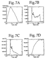
- Example 2 All conditions were nominally identical to Example 1 except that because the acetal polymer insulator had been fractured at the output end a lap joint was made in the insulator and the last (18 inches) was replaced with an insulation portion comprised of G-10 fiberglass. Electrical performance was similar (see FIGS. 7A, 7B, 7C and 7D), subject to the random variations inherent in the fuse 42. A peak power of 442 megawatts was observed and a total of 182.3 kilojoules was coupled. The apparatus with the G-10 fiberglass insulator survived and was reusable.
- the conditions of the capacitor bank 28, blasting probe 14, working fluid and explodable conductor 16 were identical to those of Example 2.
- the peak rate of electrical power transfer was 450 megawatts.
- a total energy of 178.3 kilojoules was coupled to the fuse (see FIGS. 8A, 8B, 8C and 8D.)
- the apparatus 10 blasted a concrete test sample, as depicted in FIG. 5.
- the violence of the blast was significant.
- the concrete test sample was fractured into at least 23 pieces, whose maximum linear dimensions range from 25.4 cm to 88.9 cm (10 inches to 35 inches), mean +/- standard deviation was 48.3 cm +/- 17.8 cm (19 inches +/- 7 inches). Numerous smaller pieces were also produced. Some of the larger pieces were thrown about 9 m (30 feet) from the test area.
- the explodable conductor 16 was properly matched to the driver circuit 12 characteristics.
- the only change in the initial conditions of the capacitor bank was in voltage V. Therefore, from the relations l ⁇ (LC) 1/4 V; A ⁇ C 3/4 L -1/4 V, both l and A were reduced to one-half their previous values.
- the explosion was considerably less violent than that of Example 3 because only 52.4 kilojoules of electrical energy was stored in the capacitor bank and 42.5 kilojoules was coupled to the explodable conductor 16. Peak electric power was 59.6 megawatts. See FIGS. 9A, 9B, 9C, and 9D.
- the concrete test sample was broken into four large pieces with only a stored energy of 52.4 kilojoules.
- the capacitor bank was charged to 5 kilovolts and the full 11.4 cm (4.5 inches) of working fluid was employed to determine whether only 52.4 kilojoules of stored energy could be used to release chemical energy via the aluminum-oxygen reaction.
- the explodable conductors 16' had the same length and thickness as the explodable conductor 16 used in Example 4 because it was still required to couple the 5 kilovolt bank.
- Example 5 was successful in enhancing energy output, breaking the test sample into 10 large pieces.
- the capacitor bank 28 was charged to 10 kilovolts and the single helix 50.8 cm (20 inches) long explodable conductor 16, 0.14 mm (5.5 mil) thick, 3.8 cm (1.5 inches) wide, the fuse was wound on a 11.4 cm (4.5 inches) long mandrel 108.
- the working fluid was pure water having no aluminum therein, thus providing no chemical augmentation to the plasma energy release.
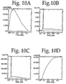
- the higher dielectric constant of water as compared with the aluminum loaded water increased the effective impedance of the plasma thereby leading to the generation of a high sustained voltage drop at the fuse with good power dissipation thereat. Peak power was 658 megawatts and 174.2 kilojoules of electrical energy was coupled to the fuse (see FIGS. 11A, 11B, 11C and 11D).
- the concrete test sample was fractured into 13 large fragments.
Landscapes
- Engineering & Computer Science (AREA)
- Mining & Mineral Resources (AREA)
- Life Sciences & Earth Sciences (AREA)
- Geology (AREA)
- General Life Sciences & Earth Sciences (AREA)
- Geochemistry & Mineralogy (AREA)
- Environmental & Geological Engineering (AREA)
- Physics & Mathematics (AREA)
- General Engineering & Computer Science (AREA)
- Fluid Mechanics (AREA)
- Drilling And Exploitation, And Mining Machines And Methods (AREA)
- Coating By Spraying Or Casting (AREA)
- Earth Drilling (AREA)
- Generation Of Surge Voltage And Current (AREA)
- Fixed Capacitors And Capacitor Manufacturing Machines (AREA)
- Physical Or Chemical Processes And Apparatus (AREA)
- Manufacture Of Alloys Or Alloy Compounds (AREA)
- Arc Welding In General (AREA)
Claims (9)
- Vorrichtung (10) zum Plasmasprengen eines Feststoffs mit:gekennzeichnet durchkapazitiven Mitteln (28) zum Speichern von elektrischer Energie;einem sprengbaren Leiter (16), der eine gegebene Länge und einen gegebenen Querschnitt besitzt und der elektrisch mit den kapazitiven Mitteln verbunden ist, um elektrischen Strom zu erhalten, wobei der elektrische Strom den sprengbaren Leiter (16) von einem Festkörper zu einem Plasma erhitzt in Nachbarschaft mit einer verdampfbaren Arbeitsflüssigkeit, um Arbeit an dem Festkörper auszuführen; undSchaltmitteln (46), die selektiv das elektrische Ladepotential der kapazitiven Mittel (28) mit dem sprengbaren Leiter (16) verbinden;
induktive Mittel (66), die mit den kapazitiven Mitteln (28) verbunden sind, um den Fluss der elektrischen Ladung zu empfangen und die Änderungsrate des elektrischen Stroms zu dem sprengbaren Leiter (16) zu verlangsamen, wobei der Anstieg bezüglich des Widerstands des sprengbaren Leiters auftritt, wenn er vom Festkörper zum Plasma wechselt, was Strom zu dem Plasma veranlasst, um einen erhöhten Spannungsabfall über dem Plasma zu erzeugen, mit dem Ergebnis erhöhter Wärmeabgabe an die Arbeitsflüssigkeit, wobei die Quadratwurzel des Verhältnisses der Induktanz der induktiven Mittel (66) geteilt durch die Kapazität der Kapazititäsmittel (28) proportional ist zum Verhältnis der Länge des sprengbaren Leiters (16) geteilt durch seinen Querschnitt und wobei das Volumen des sprengbaren Leiters proportional ist zur elektrischen Energie, die in den kapazititiven Mitteln (28) gespeichert ist, um optimalen Energietransfer von den kapazitiven Mitteln (28) zu dem sprengbaren Leiter (16) zu erreichen. - Vorrichtung zum Plasmasprengen eines Festkörpers nach Anspruch 1, wobei der sprengbare Leiter (16) einen Bogen leitfähigen Materials mit einem relativ großen Oberflächenbereich-Zu-Volumen-Verhältis aufweist.
- Vorrichtung zum Plasmasprengen eines Festkörpers nach Anspruch 1, wobei der sprengbare Leiter (16) ein Metallband umfasst.
- Vorrichtung zum Plasmasprengen eines Festkörpers nach Anspruch 1, wobei der sprengbare Leiter (16) ein spiralförmiges Band umfasst, das um einen unterstützenden Körper (108) gewunden ist.
- Verfahren zm Plasmasprengen eines Festkörpers mit den Schritten:gekennzeichnet durchAufladen einer Kapazität (28) mit einer elektrischen Ladung; und
Übertragen der elektrischen Ladung durch eine Induktivität (66) zu einem sprengbaren Leiter (16), wobei die Quadratwurzel des Verhältnisses der Induktanz (66) zu der Kapazität (28) proportional ist zu einer Länge des sprengbaren Leiters (16) geteilt durch seine Querschnittsfläche und das Volumen des sprengbaren Leiters proportional ist zur elektrischen Energie, die in der Kapazität (28) gespeichert ist. - Verfahren zum Plasmasprengen eines Festkörpers nach Anspruch 5, ferner mit dem Schritt des Plazierens des sprengbaren Leiters (16) in Nachbarschaft mit einem pulverisierten Metall und einer Oxidationsmittelmischung, so dass die Umwandlung des sprengbaren Leiters zu Plasma die Mischung veranlasst zu reagieren und Wärmeenergie freizusetzen, um die Explosionskraft des sprengbaren Leiters zu erhöhen.
- Verfahren zum Plasmasprengen eines Festkörpers nach Anspruch 6, bei dem das pulverisierte Material Aluminum ist.
- Verfahren zum Plasmasprengen eines Festkörpers nach Anspruch 7, wobei das Oxidationsmittel Wasser umfasst.
- Verfahren zum Plasmasprengen eines Festkörpers nach Anspruch 8, bei dem ein Geliermittel kombiniert ist mit dem Aluminium und dem Wasser, um das Aluminum und das Wasser in Nachbarschaft mit dem sprengbaren Leiter zu halten.
Applications Claiming Priority (3)
| Application Number | Priority Date | Filing Date | Title |
|---|---|---|---|
| US08/193,233 US5425570A (en) | 1994-01-21 | 1994-01-21 | Method and apparatus for plasma blasting |
| US193233 | 1994-01-21 | ||
| PCT/US1995/000640 WO1995020097A1 (en) | 1994-01-21 | 1995-01-20 | Method and apparatus for plasma blasting |
Publications (3)
| Publication Number | Publication Date |
|---|---|
| EP0740737A1 EP0740737A1 (de) | 1996-11-06 |
| EP0740737A4 EP0740737A4 (de) | 1999-12-01 |
| EP0740737B1 true EP0740737B1 (de) | 2002-05-02 |
Family
ID=22712760
Family Applications (1)
| Application Number | Title | Priority Date | Filing Date |
|---|---|---|---|
| EP95910098A Expired - Lifetime EP0740737B1 (de) | 1994-01-21 | 1995-01-20 | Plasmasprengverfahren und vorrichtung |
Country Status (12)
| Country | Link |
|---|---|
| US (1) | US5425570A (de) |
| EP (1) | EP0740737B1 (de) |
| JP (1) | JP3588468B2 (de) |
| KR (1) | KR100323215B1 (de) |
| AT (1) | ATE217051T1 (de) |
| AU (1) | AU677511B2 (de) |
| BR (1) | BR9506547A (de) |
| CA (1) | CA2180661C (de) |
| DE (1) | DE69526570D1 (de) |
| FI (1) | FI962915L (de) |
| RU (1) | RU2138637C1 (de) |
| WO (1) | WO1995020097A1 (de) |
Families Citing this family (48)
| Publication number | Priority date | Publication date | Assignee | Title |
|---|---|---|---|---|
| US5573307A (en) * | 1994-01-21 | 1996-11-12 | Maxwell Laboratories, Inc. | Method and apparatus for blasting hard rock |
| KR100261458B1 (ko) | 1995-07-24 | 2000-07-01 | 미나미 이조 | 방전파괴장치및방전파괴방법 |
| CN1075430C (zh) * | 1995-07-31 | 2001-11-28 | 日立造船株式会社 | 放电液压破坏法 |
| EP1013142A4 (de) * | 1996-08-05 | 2002-06-05 | Tetra Corp | Elektrohydraulische druckwellenprojektoren |
| WO1999024694A1 (en) * | 1997-11-06 | 1999-05-20 | Baggermaatschappij Boskalis B.V. | Method and device for crushing rock, manipulator to be used in such a device, assembly of a housing and a wire conductor placed therein, and assembly of a housing and a means placed therein |
| US6260483B1 (en) * | 1998-04-24 | 2001-07-17 | Richard N. Snyder | Remote radio controlled plasma firing system |
| KR100308081B1 (ko) * | 1999-03-02 | 2001-09-24 | 정기형 | 플라즈마파암용 전력충격쎌 |
| US6584905B1 (en) | 2000-11-06 | 2003-07-01 | Richard N. Snyder | Plated through-hole ignitor for detonation cord or shock tube |
| US7059249B2 (en) * | 2001-01-23 | 2006-06-13 | United Defense Lp | Transverse plasma injector ignitor |
| CN1461239A (zh) * | 2001-04-06 | 2003-12-10 | 住友电气工业株式会社 | 破碎装置用电极和破碎装置 |
| FR2839810B1 (fr) * | 2002-05-17 | 2004-11-12 | Tda Armements Sas | Commutateur a ouverture de type a fils exploses et procede de fabrication |
| US20040145354A1 (en) * | 2003-01-17 | 2004-07-29 | Stumberger Walter W. | Method for controlling an electrical discharge using electrolytes and other electrically conductive fluid materials |
| US7073447B2 (en) * | 2003-02-12 | 2006-07-11 | Bae Systems Land & Armaments L.P. | Electro-thermal chemical igniter and connector |
| DE10311659B4 (de) * | 2003-03-14 | 2006-12-21 | Sws Shock Wave Systems Ag | Vorrichtung und Verfahren zur optimierten elektrohydraulischen Druckpulserzeugung |
| US20080112107A1 (en) * | 2004-01-14 | 2008-05-15 | Stumberger Walter W | Method for controlling an electrical discharge using electrically conductive fluid materials |
| US7514819B2 (en) | 2004-07-01 | 2009-04-07 | Dana Automotive Systems Group, Llc | Semiconductor switch assembly for pulse power apparatus |
| US7416032B2 (en) * | 2004-08-20 | 2008-08-26 | Tetra Corporation | Pulsed electric rock drilling apparatus |
| US8172006B2 (en) | 2004-08-20 | 2012-05-08 | Sdg, Llc | Pulsed electric rock drilling apparatus with non-rotating bit |
| US8789772B2 (en) | 2004-08-20 | 2014-07-29 | Sdg, Llc | Virtual electrode mineral particle disintegrator |
| US7959094B2 (en) * | 2004-08-20 | 2011-06-14 | Tetra Corporation | Virtual electrode mineral particle disintegrator |
| US7559378B2 (en) * | 2004-08-20 | 2009-07-14 | Tetra Corporation | Portable and directional electrocrushing drill |
| US9190190B1 (en) | 2004-08-20 | 2015-11-17 | Sdg, Llc | Method of providing a high permittivity fluid |
| US7527108B2 (en) * | 2004-08-20 | 2009-05-05 | Tetra Corporation | Portable electrocrushing drill |
| US8186454B2 (en) * | 2004-08-20 | 2012-05-29 | Sdg, Llc | Apparatus and method for electrocrushing rock |
| US8161877B1 (en) | 2005-12-07 | 2012-04-24 | The United States Of America As Represented By The United States Department Of Energy | Electronic firing systems and methods for firing a device |
| US8701560B2 (en) | 2010-11-22 | 2014-04-22 | Battelle Energy Alliance, Llc | Apparatus, system, and method for synchronizing a timer key |
| US20070125256A1 (en) * | 2005-12-07 | 2007-06-07 | Battelle Energy Alliance, Llc | Electronic firing systems and methods for firing a device |
| US10060195B2 (en) | 2006-06-29 | 2018-08-28 | Sdg Llc | Repetitive pulsed electric discharge apparatuses and methods of use |
| US7457155B2 (en) * | 2006-08-31 | 2008-11-25 | Micron Technology, Inc. | Non-volatile memory device and method having bit-state assignments selected to minimize signal coupling |
| SK50872007A3 (sk) | 2007-06-29 | 2009-01-07 | Ivan Kočiš | Zariadenie na exkaváciu hlbinných otvorov v geologickej formácii a spôsob prepravy energií a materiálu v týchto otvoroch |
| SK288264B6 (sk) | 2009-02-05 | 2015-05-05 | Ga Drilling, A. S. | Zariadenie na vykonávanie hĺbkových vrtov a spôsob vykonávania hĺbkových vrtov |
| SK50622009A3 (sk) | 2009-09-24 | 2011-05-06 | Ivan Kočiš | Spôsob rozrušovania materiálov a zariadenie na vykonávanie tohto spôsobu |
| CA2860775A1 (en) | 2011-01-07 | 2012-07-12 | Sdg Llc | Apparatus and method for supplying electrical power to an electrocrushing drill |
| US10407995B2 (en) | 2012-07-05 | 2019-09-10 | Sdg Llc | Repetitive pulsed electric discharge drills including downhole formation evaluation |
| US9181788B2 (en) | 2012-07-27 | 2015-11-10 | Novas Energy Group Limited | Plasma source for generating nonlinear, wide-band, periodic, directed, elastic oscillations and a system and method for stimulating wells, deposits and boreholes using the plasma source |
| US10077644B2 (en) | 2013-03-15 | 2018-09-18 | Chevron U.S.A. Inc. | Method and apparatus for generating high-pressure pulses in a subterranean dielectric medium |
| CN103267830B (zh) * | 2013-05-09 | 2015-04-29 | 西安交通大学 | 评价固体含能材料在等离子体射流作用下烧蚀特性的方法 |
| US10113364B2 (en) | 2013-09-23 | 2018-10-30 | Sdg Llc | Method and apparatus for isolating and switching lower voltage pulses from high voltage pulses in electrocrushing and electrohydraulic drills |
| US10128952B2 (en) * | 2016-01-05 | 2018-11-13 | Morton Photonics | Silicon photonics receive phased array sensors |
| JP2018053573A (ja) * | 2016-09-29 | 2018-04-05 | 国立研究開発法人海洋研究開発機構 | 地盤掘削装置 |
| CN108180003B (zh) * | 2018-01-12 | 2019-02-12 | 西安交通大学 | 金属丝电爆炸驱动含能混合物产生水中冲击波的方法 |
| US10577767B2 (en) * | 2018-02-20 | 2020-03-03 | Petram Technologies, Inc. | In-situ piling and anchor shaping using plasma blasting |
| US10844702B2 (en) * | 2018-03-20 | 2020-11-24 | Petram Technologies, Inc. | Precision utility mapping and excavating using plasma blasting |
| USD904305S1 (en) * | 2019-02-25 | 2020-12-08 | Petram Technologies, Inc. | Electrode cage for a plasma blasting probe |
| US11536090B2 (en) | 2020-12-16 | 2022-12-27 | Halliburton Energy Services, Inc. | Voltage line communications during pulse power drilling |
| US11203400B1 (en) | 2021-06-17 | 2021-12-21 | General Technologies Corp. | Support system having shaped pile-anchor foundations and a method of forming same |
| CN113738327B (zh) * | 2021-07-28 | 2022-04-15 | 中国矿业大学 | 一种等离子体定向致裂页岩的装置和方法 |
| KR102473077B1 (ko) | 2021-11-26 | 2022-11-30 | 지에스건설 주식회사 | 화약류로 착화되는 미진동 파쇄제 조성물 및 이의 제조 방법 |
Family Cites Families (14)
| Publication number | Priority date | Publication date | Assignee | Title |
|---|---|---|---|---|
| SU357345A1 (ru) * | 1962-08-23 | 1983-07-30 | Yutkin L A | Устройство дл разрушени монолитных объектов |
| US3583766A (en) * | 1969-05-22 | 1971-06-08 | Louis R Padberg Jr | Apparatus for facilitating the extraction of minerals from the ocean floor |
| US3679007A (en) * | 1970-05-25 | 1972-07-25 | Louis Richard O Hare | Shock plasma earth drill |
| US4343356A (en) * | 1972-10-06 | 1982-08-10 | Sonics International, Inc. | Method and apparatus for treating subsurface boreholes |
| US4334474A (en) * | 1976-05-21 | 1982-06-15 | The United States Of America As Represented By The Secretary Of The Navy | Warhead initiation system |
| US4479680A (en) * | 1980-04-11 | 1984-10-30 | Wesley Richard H | Method and apparatus for electrohydraulic fracturing of rock and the like |
| US4974487A (en) * | 1984-10-05 | 1990-12-04 | Gt-Devices | Plasma propulsion apparatus and method |
| SU1391231A1 (ru) * | 1986-05-13 | 1995-02-20 | Проектно-конструкторское бюро электрогидравлики АН УССР | Установка для разрушения монолитных образований |
| US4741405A (en) * | 1987-01-06 | 1988-05-03 | Tetra Corporation | Focused shock spark discharge drill using multiple electrodes |
| CA1289171C (en) * | 1987-07-20 | 1991-09-17 | Noranda Inc. | Electromechanically triggered spark gap switch |
| US5072647A (en) * | 1989-02-10 | 1991-12-17 | Gt-Devices | High-pressure having plasma flow transverse to plasma discharge particularly for projectile acceleration |
| US5083615A (en) * | 1990-01-26 | 1992-01-28 | The Board Of Supervisors Of Louisiana State University And Agricultural And Mechanical College | Aluminum alkyls used to create multiple fractures |
| ZA91612B (en) * | 1990-04-20 | 1991-10-30 | Noranda Inc | Plasma blasting method |
| US5052272A (en) * | 1990-08-06 | 1991-10-01 | The United States Of America As Represented By The Secretary Of The Navy | Launching projectiles with hydrogen gas generated from aluminum fuel powder/water reactions |
-
1994
- 1994-01-21 US US08/193,233 patent/US5425570A/en not_active Expired - Lifetime
-
1995
- 1995-01-20 RU RU96116518A patent/RU2138637C1/ru active
- 1995-01-20 DE DE69526570T patent/DE69526570D1/de not_active Expired - Lifetime
- 1995-01-20 CA CA002180661A patent/CA2180661C/en not_active Expired - Fee Related
- 1995-01-20 JP JP51962695A patent/JP3588468B2/ja not_active Expired - Fee Related
- 1995-01-20 AT AT95910098T patent/ATE217051T1/de not_active IP Right Cessation
- 1995-01-20 WO PCT/US1995/000640 patent/WO1995020097A1/en not_active Ceased
- 1995-01-20 FI FI962915A patent/FI962915L/fi unknown
- 1995-01-20 EP EP95910098A patent/EP0740737B1/de not_active Expired - Lifetime
- 1995-01-20 BR BR9506547A patent/BR9506547A/pt not_active Application Discontinuation
- 1995-01-20 AU AU18321/95A patent/AU677511B2/en not_active Ceased
- 1995-01-20 KR KR1019960703970A patent/KR100323215B1/ko not_active Expired - Fee Related
Also Published As
| Publication number | Publication date |
|---|---|
| CA2180661A1 (en) | 1995-07-27 |
| AU677511B2 (en) | 1997-04-24 |
| JP3588468B2 (ja) | 2004-11-10 |
| FI962915A7 (fi) | 1996-09-19 |
| EP0740737A4 (de) | 1999-12-01 |
| BR9506547A (pt) | 1997-08-19 |
| KR100323215B1 (ko) | 2002-06-22 |
| FI962915L (fi) | 1996-09-19 |
| CA2180661C (en) | 2005-01-18 |
| JPH09511035A (ja) | 1997-11-04 |
| US5425570A (en) | 1995-06-20 |
| FI962915A0 (fi) | 1996-07-19 |
| ATE217051T1 (de) | 2002-05-15 |
| WO1995020097A1 (en) | 1995-07-27 |
| RU2138637C1 (ru) | 1999-09-27 |
| EP0740737A1 (de) | 1996-11-06 |
| DE69526570D1 (de) | 2002-06-06 |
| AU1832195A (en) | 1995-08-08 |
Similar Documents
| Publication | Publication Date | Title |
|---|---|---|
| US5425570A (en) | Method and apparatus for plasma blasting | |
| EP0824625B1 (de) | Verfahren und vorrichtung zum sprengen von hartstein | |
| US4741405A (en) | Focused shock spark discharge drill using multiple electrodes | |
| US6215734B1 (en) | Electrohydraulic pressure wave projectors | |
| US10077644B2 (en) | Method and apparatus for generating high-pressure pulses in a subterranean dielectric medium | |
| US5106164A (en) | Plasma blasting method | |
| US4653697A (en) | Method and apparatus for fragmenting a substance by the discharge of pulsed electrical energy | |
| US5004050A (en) | Method for well stimulation in the process of oil production and device for carrying same into effect | |
| EP0453076B1 (de) | Plasmasprengverfahren | |
| CA2220920C (en) | Method and apparatus for blasting hard rock | |
| US7218016B2 (en) | Explosively driven radio frequency pulse generating apparatus | |
| US11536124B2 (en) | Sliced and elliptical head probe for plasma blast applications | |
| RU2150652C1 (ru) | Коаксиальный ускоритель сивкова | |
| US20250290414A1 (en) | Robust Plasma Blast Probe Apparatus and Method | |
| RU2774308C1 (ru) | Скважинный источник электрогидравлического разряда с узлами электромеханического контактора-разрядника, высоковольтного электрода и механизмом подачи калиброванного проводника | |
| HK1015012B (en) | Method and apparatus for blasting hard rock | |
| CA2321810A1 (en) | Electric pulse blasting device |
Legal Events
| Date | Code | Title | Description |
|---|---|---|---|
| PUAI | Public reference made under article 153(3) epc to a published international application that has entered the european phase |
Free format text: ORIGINAL CODE: 0009012 |
|
| 17P | Request for examination filed |
Effective date: 19960729 |
|
| AK | Designated contracting states |
Kind code of ref document: A1 Designated state(s): AT CH DE FR GB IT LI SE |
|
| RAP1 | Party data changed (applicant data changed or rights of an application transferred) |
Owner name: MAXWELL TECHNOLOGIES, INC. |
|
| A4 | Supplementary search report drawn up and despatched |
Effective date: 19991019 |
|
| AK | Designated contracting states |
Kind code of ref document: A4 Designated state(s): AT CH DE FR GB IT LI SE |
|
| 17Q | First examination report despatched |
Effective date: 20000522 |
|
| GRAG | Despatch of communication of intention to grant |
Free format text: ORIGINAL CODE: EPIDOS AGRA |
|
| GRAG | Despatch of communication of intention to grant |
Free format text: ORIGINAL CODE: EPIDOS AGRA |
|
| GRAG | Despatch of communication of intention to grant |
Free format text: ORIGINAL CODE: EPIDOS AGRA |
|
| GRAH | Despatch of communication of intention to grant a patent |
Free format text: ORIGINAL CODE: EPIDOS IGRA |
|
| RAP1 | Party data changed (applicant data changed or rights of an application transferred) |
Owner name: THE TITAN CORPORATION |
|
| RAP1 | Party data changed (applicant data changed or rights of an application transferred) |
Owner name: TITAN CORPORATION |
|
| GRAH | Despatch of communication of intention to grant a patent |
Free format text: ORIGINAL CODE: EPIDOS IGRA |
|
| REG | Reference to a national code |
Ref country code: GB Ref legal event code: IF02 |
|
| GRAA | (expected) grant |
Free format text: ORIGINAL CODE: 0009210 |
|
| AK | Designated contracting states |
Kind code of ref document: B1 Designated state(s): AT CH DE FR GB IT LI SE |
|
| PG25 | Lapsed in a contracting state [announced via postgrant information from national office to epo] |
Ref country code: LI Free format text: LAPSE BECAUSE OF FAILURE TO SUBMIT A TRANSLATION OF THE DESCRIPTION OR TO PAY THE FEE WITHIN THE PRESCRIBED TIME-LIMIT Effective date: 20020502 Ref country code: IT Free format text: LAPSE BECAUSE OF FAILURE TO SUBMIT A TRANSLATION OF THE DESCRIPTION OR TO PAY THE FEE WITHIN THE PRE;WARNING: LAPSES OF ITALIAN PATENTS WITH EFFECTIVE DATE BEFORE 2007 MAY HAVE OCCURRED AT ANY TIME BEFORE 2007. THE CORRECT EFFECTIVE DATE MAY BE DIFFERENT FROM THE ONE RECORDED.SCRIBED TIME-LIMIT Effective date: 20020502 Ref country code: FR Free format text: LAPSE BECAUSE OF FAILURE TO SUBMIT A TRANSLATION OF THE DESCRIPTION OR TO PAY THE FEE WITHIN THE PRESCRIBED TIME-LIMIT Effective date: 20020502 Ref country code: CH Free format text: LAPSE BECAUSE OF FAILURE TO SUBMIT A TRANSLATION OF THE DESCRIPTION OR TO PAY THE FEE WITHIN THE PRESCRIBED TIME-LIMIT Effective date: 20020502 Ref country code: AT Free format text: LAPSE BECAUSE OF FAILURE TO SUBMIT A TRANSLATION OF THE DESCRIPTION OR TO PAY THE FEE WITHIN THE PRESCRIBED TIME-LIMIT Effective date: 20020502 |
|
| REF | Corresponds to: |
Ref document number: 217051 Country of ref document: AT Date of ref document: 20020515 Kind code of ref document: T |
|
| REG | Reference to a national code |
Ref country code: GB Ref legal event code: FG4D |
|
| REG | Reference to a national code |
Ref country code: CH Ref legal event code: EP |
|
| REF | Corresponds to: |
Ref document number: 69526570 Country of ref document: DE Date of ref document: 20020606 |
|
| PG25 | Lapsed in a contracting state [announced via postgrant information from national office to epo] |
Ref country code: SE Free format text: LAPSE BECAUSE OF FAILURE TO SUBMIT A TRANSLATION OF THE DESCRIPTION OR TO PAY THE FEE WITHIN THE PRESCRIBED TIME-LIMIT Effective date: 20020802 |
|
| PG25 | Lapsed in a contracting state [announced via postgrant information from national office to epo] |
Ref country code: DE Free format text: LAPSE BECAUSE OF FAILURE TO SUBMIT A TRANSLATION OF THE DESCRIPTION OR TO PAY THE FEE WITHIN THE PRESCRIBED TIME-LIMIT Effective date: 20020803 |
|
| REG | Reference to a national code |
Ref country code: CH Ref legal event code: PL |
|
| EN | Fr: translation not filed | ||
| PG25 | Lapsed in a contracting state [announced via postgrant information from national office to epo] |
Ref country code: GB Free format text: LAPSE BECAUSE OF NON-PAYMENT OF DUE FEES Effective date: 20030120 |
|
| PLBE | No opposition filed within time limit |
Free format text: ORIGINAL CODE: 0009261 |
|
| STAA | Information on the status of an ep patent application or granted ep patent |
Free format text: STATUS: NO OPPOSITION FILED WITHIN TIME LIMIT |
|
| 26N | No opposition filed |
Effective date: 20030204 |
|
| GBPC | Gb: european patent ceased through non-payment of renewal fee |