EP0740239B1 - Numerical control - Google Patents
Numerical control Download PDFInfo
- Publication number
- EP0740239B1 EP0740239B1 EP96109691A EP96109691A EP0740239B1 EP 0740239 B1 EP0740239 B1 EP 0740239B1 EP 96109691 A EP96109691 A EP 96109691A EP 96109691 A EP96109691 A EP 96109691A EP 0740239 B1 EP0740239 B1 EP 0740239B1
- Authority
- EP
- European Patent Office
- Prior art keywords
- data
- screen
- unit
- file
- shows
- Prior art date
- Legal status (The legal status is an assumption and is not a legal conclusion. Google has not performed a legal analysis and makes no representation as to the accuracy of the status listed.)
- Expired - Lifetime
Links
Images


Classifications
-
- G—PHYSICS
- G05—CONTROLLING; REGULATING
- G05B—CONTROL OR REGULATING SYSTEMS IN GENERAL; FUNCTIONAL ELEMENTS OF SUCH SYSTEMS; MONITORING OR TESTING ARRANGEMENTS FOR SUCH SYSTEMS OR ELEMENTS
- G05B19/00—Programme-control systems
- G05B19/02—Programme-control systems electric
- G05B19/18—Numerical control [NC], i.e. automatically operating machines, in particular machine tools, e.g. in a manufacturing environment, so as to execute positioning, movement or co-ordinated operations by means of programme data in numerical form
- G05B19/409—Numerical control [NC], i.e. automatically operating machines, in particular machine tools, e.g. in a manufacturing environment, so as to execute positioning, movement or co-ordinated operations by means of programme data in numerical form characterised by using manual input [MDI] or by using control panel, e.g. controlling functions with the panel; characterised by control panel details, by setting parameters
-
- G—PHYSICS
- G05—CONTROLLING; REGULATING
- G05B—CONTROL OR REGULATING SYSTEMS IN GENERAL; FUNCTIONAL ELEMENTS OF SUCH SYSTEMS; MONITORING OR TESTING ARRANGEMENTS FOR SUCH SYSTEMS OR ELEMENTS
- G05B19/00—Programme-control systems
- G05B19/02—Programme-control systems electric
- G05B19/18—Numerical control [NC], i.e. automatically operating machines, in particular machine tools, e.g. in a manufacturing environment, so as to execute positioning, movement or co-ordinated operations by means of programme data in numerical form
- G05B19/408—Numerical control [NC], i.e. automatically operating machines, in particular machine tools, e.g. in a manufacturing environment, so as to execute positioning, movement or co-ordinated operations by means of programme data in numerical form characterised by data handling or data format, e.g. reading, buffering or conversion of data
-
- G—PHYSICS
- G05—CONTROLLING; REGULATING
- G05B—CONTROL OR REGULATING SYSTEMS IN GENERAL; FUNCTIONAL ELEMENTS OF SUCH SYSTEMS; MONITORING OR TESTING ARRANGEMENTS FOR SUCH SYSTEMS OR ELEMENTS
- G05B19/00—Programme-control systems
- G05B19/02—Programme-control systems electric
- G05B19/18—Numerical control [NC], i.e. automatically operating machines, in particular machine tools, e.g. in a manufacturing environment, so as to execute positioning, movement or co-ordinated operations by means of programme data in numerical form
- G05B19/4093—Numerical control [NC], i.e. automatically operating machines, in particular machine tools, e.g. in a manufacturing environment, so as to execute positioning, movement or co-ordinated operations by means of programme data in numerical form characterised by part programming, e.g. entry of geometrical information as taken from a technical drawing, combining this with machining and material information to obtain control information, named part programme, for the NC machine
- G05B19/40931—Numerical control [NC], i.e. automatically operating machines, in particular machine tools, e.g. in a manufacturing environment, so as to execute positioning, movement or co-ordinated operations by means of programme data in numerical form characterised by part programming, e.g. entry of geometrical information as taken from a technical drawing, combining this with machining and material information to obtain control information, named part programme, for the NC machine concerning programming of geometry
- G05B19/40935—Selection of predetermined shapes and defining the dimensions with parameter input
-
- G—PHYSICS
- G05—CONTROLLING; REGULATING
- G05B—CONTROL OR REGULATING SYSTEMS IN GENERAL; FUNCTIONAL ELEMENTS OF SUCH SYSTEMS; MONITORING OR TESTING ARRANGEMENTS FOR SUCH SYSTEMS OR ELEMENTS
- G05B2219/00—Program-control systems
- G05B2219/30—Nc systems
- G05B2219/34—Director, elements to supervisory
- G05B2219/34392—Stop program on detection of undefined variable, symbol, enter definition, continue
-
- G—PHYSICS
- G05—CONTROLLING; REGULATING
- G05B—CONTROL OR REGULATING SYSTEMS IN GENERAL; FUNCTIONAL ELEMENTS OF SUCH SYSTEMS; MONITORING OR TESTING ARRANGEMENTS FOR SUCH SYSTEMS OR ELEMENTS
- G05B2219/00—Program-control systems
- G05B2219/30—Nc systems
- G05B2219/35—Nc in input of data, input till input file format
- G05B2219/35261—Use of mathematical expression, functional equation
-
- G—PHYSICS
- G05—CONTROLLING; REGULATING
- G05B—CONTROL OR REGULATING SYSTEMS IN GENERAL; FUNCTIONAL ELEMENTS OF SUCH SYSTEMS; MONITORING OR TESTING ARRANGEMENTS FOR SUCH SYSTEMS OR ELEMENTS
- G05B2219/00—Program-control systems
- G05B2219/30—Nc systems
- G05B2219/35—Nc in input of data, input till input file format
- G05B2219/35263—Using variables, parameters in program, macro, parametrized instruction
-
- G—PHYSICS
- G05—CONTROLLING; REGULATING
- G05B—CONTROL OR REGULATING SYSTEMS IN GENERAL; FUNCTIONAL ELEMENTS OF SUCH SYSTEMS; MONITORING OR TESTING ARRANGEMENTS FOR SUCH SYSTEMS OR ELEMENTS
- G05B2219/00—Program-control systems
- G05B2219/30—Nc systems
- G05B2219/35—Nc in input of data, input till input file format
- G05B2219/35267—Compare ram data to rom data, verify correctness, validity data, tolerance
-
- G—PHYSICS
- G05—CONTROLLING; REGULATING
- G05B—CONTROL OR REGULATING SYSTEMS IN GENERAL; FUNCTIONAL ELEMENTS OF SUCH SYSTEMS; MONITORING OR TESTING ARRANGEMENTS FOR SUCH SYSTEMS OR ELEMENTS
- G05B2219/00—Program-control systems
- G05B2219/30—Nc systems
- G05B2219/35—Nc in input of data, input till input file format
- G05B2219/35285—Plausibility check for data, within permissible range
-
- G—PHYSICS
- G05—CONTROLLING; REGULATING
- G05B—CONTROL OR REGULATING SYSTEMS IN GENERAL; FUNCTIONAL ELEMENTS OF SUCH SYSTEMS; MONITORING OR TESTING ARRANGEMENTS FOR SUCH SYSTEMS OR ELEMENTS
- G05B2219/00—Program-control systems
- G05B2219/30—Nc systems
- G05B2219/35—Nc in input of data, input till input file format
- G05B2219/35368—Read and work buffer, machine while read in, no switching between buffers
-
- G—PHYSICS
- G05—CONTROLLING; REGULATING
- G05B—CONTROL OR REGULATING SYSTEMS IN GENERAL; FUNCTIONAL ELEMENTS OF SUCH SYSTEMS; MONITORING OR TESTING ARRANGEMENTS FOR SUCH SYSTEMS OR ELEMENTS
- G05B2219/00—Program-control systems
- G05B2219/30—Nc systems
- G05B2219/35—Nc in input of data, input till input file format
- G05B2219/35373—Data storage, buffer
-
- G—PHYSICS
- G05—CONTROLLING; REGULATING
- G05B—CONTROL OR REGULATING SYSTEMS IN GENERAL; FUNCTIONAL ELEMENTS OF SUCH SYSTEMS; MONITORING OR TESTING ARRANGEMENTS FOR SUCH SYSTEMS OR ELEMENTS
- G05B2219/00—Program-control systems
- G05B2219/30—Nc systems
- G05B2219/35—Nc in input of data, input till input file format
- G05B2219/35376—Input program, analyze, store to buffer ready to control nc, no further data handling
-
- G—PHYSICS
- G05—CONTROLLING; REGULATING
- G05B—CONTROL OR REGULATING SYSTEMS IN GENERAL; FUNCTIONAL ELEMENTS OF SUCH SYSTEMS; MONITORING OR TESTING ARRANGEMENTS FOR SUCH SYSTEMS OR ELEMENTS
- G05B2219/00—Program-control systems
- G05B2219/30—Nc systems
- G05B2219/35—Nc in input of data, input till input file format
- G05B2219/35426—Prepare, enter next program during execution of actual program, machining
-
- G—PHYSICS
- G05—CONTROLLING; REGULATING
- G05B—CONTROL OR REGULATING SYSTEMS IN GENERAL; FUNCTIONAL ELEMENTS OF SUCH SYSTEMS; MONITORING OR TESTING ARRANGEMENTS FOR SUCH SYSTEMS OR ELEMENTS
- G05B2219/00—Program-control systems
- G05B2219/30—Nc systems
- G05B2219/35—Nc in input of data, input till input file format
- G05B2219/35435—Display, if needed, tolerance memo data at place where real data must be input
-
- G—PHYSICS
- G05—CONTROLLING; REGULATING
- G05B—CONTROL OR REGULATING SYSTEMS IN GENERAL; FUNCTIONAL ELEMENTS OF SUCH SYSTEMS; MONITORING OR TESTING ARRANGEMENTS FOR SUCH SYSTEMS OR ELEMENTS
- G05B2219/00—Program-control systems
- G05B2219/30—Nc systems
- G05B2219/35—Nc in input of data, input till input file format
- G05B2219/35568—Array structure corresponding to display format
-
- G—PHYSICS
- G05—CONTROLLING; REGULATING
- G05B—CONTROL OR REGULATING SYSTEMS IN GENERAL; FUNCTIONAL ELEMENTS OF SUCH SYSTEMS; MONITORING OR TESTING ARRANGEMENTS FOR SUCH SYSTEMS OR ELEMENTS
- G05B2219/00—Program-control systems
- G05B2219/30—Nc systems
- G05B2219/35—Nc in input of data, input till input file format
- G05B2219/35572—Data contains header and type of data
-
- G—PHYSICS
- G05—CONTROLLING; REGULATING
- G05B—CONTROL OR REGULATING SYSTEMS IN GENERAL; FUNCTIONAL ELEMENTS OF SUCH SYSTEMS; MONITORING OR TESTING ARRANGEMENTS FOR SUCH SYSTEMS OR ELEMENTS
- G05B2219/00—Program-control systems
- G05B2219/30—Nc systems
- G05B2219/35—Nc in input of data, input till input file format
- G05B2219/35574—Header with information for display position
-
- G—PHYSICS
- G05—CONTROLLING; REGULATING
- G05B—CONTROL OR REGULATING SYSTEMS IN GENERAL; FUNCTIONAL ELEMENTS OF SUCH SYSTEMS; MONITORING OR TESTING ARRANGEMENTS FOR SUCH SYSTEMS OR ELEMENTS
- G05B2219/00—Program-control systems
- G05B2219/30—Nc systems
- G05B2219/36—Nc in input of data, input key till input tape
- G05B2219/36051—Store history of modified file, back-up, update, using different file extensions
-
- G—PHYSICS
- G05—CONTROLLING; REGULATING
- G05B—CONTROL OR REGULATING SYSTEMS IN GENERAL; FUNCTIONAL ELEMENTS OF SUCH SYSTEMS; MONITORING OR TESTING ARRANGEMENTS FOR SUCH SYSTEMS OR ELEMENTS
- G05B2219/00—Program-control systems
- G05B2219/30—Nc systems
- G05B2219/36—Nc in input of data, input key till input tape
- G05B2219/36055—Separate, temporary memory or special storage region for corrections only
-
- G—PHYSICS
- G05—CONTROLLING; REGULATING
- G05B—CONTROL OR REGULATING SYSTEMS IN GENERAL; FUNCTIONAL ELEMENTS OF SUCH SYSTEMS; MONITORING OR TESTING ARRANGEMENTS FOR SUCH SYSTEMS OR ELEMENTS
- G05B2219/00—Program-control systems
- G05B2219/30—Nc systems
- G05B2219/36—Nc in input of data, input key till input tape
- G05B2219/36061—Storage, memory area to store history data for previous corrections, editable
-
- G—PHYSICS
- G05—CONTROLLING; REGULATING
- G05B—CONTROL OR REGULATING SYSTEMS IN GENERAL; FUNCTIONAL ELEMENTS OF SUCH SYSTEMS; MONITORING OR TESTING ARRANGEMENTS FOR SUCH SYSTEMS OR ELEMENTS
- G05B2219/00—Program-control systems
- G05B2219/30—Nc systems
- G05B2219/36—Nc in input of data, input key till input tape
- G05B2219/36073—Display original and modified part in different colour, highlight, shading, filling
-
- G—PHYSICS
- G05—CONTROLLING; REGULATING
- G05B—CONTROL OR REGULATING SYSTEMS IN GENERAL; FUNCTIONAL ELEMENTS OF SUCH SYSTEMS; MONITORING OR TESTING ARRANGEMENTS FOR SUCH SYSTEMS OR ELEMENTS
- G05B2219/00—Program-control systems
- G05B2219/30—Nc systems
- G05B2219/36—Nc in input of data, input key till input tape
- G05B2219/36111—Local memory instead of tape, or combined
-
- G—PHYSICS
- G05—CONTROLLING; REGULATING
- G05B—CONTROL OR REGULATING SYSTEMS IN GENERAL; FUNCTIONAL ELEMENTS OF SUCH SYSTEMS; MONITORING OR TESTING ARRANGEMENTS FOR SUCH SYSTEMS OR ELEMENTS
- G05B2219/00—Program-control systems
- G05B2219/30—Nc systems
- G05B2219/36—Nc in input of data, input key till input tape
- G05B2219/36124—Screen with certain display menu called by pointer, number
-
- G—PHYSICS
- G05—CONTROLLING; REGULATING
- G05B—CONTROL OR REGULATING SYSTEMS IN GENERAL; FUNCTIONAL ELEMENTS OF SUCH SYSTEMS; MONITORING OR TESTING ARRANGEMENTS FOR SUCH SYSTEMS OR ELEMENTS
- G05B2219/00—Program-control systems
- G05B2219/30—Nc systems
- G05B2219/36—Nc in input of data, input key till input tape
- G05B2219/36127—Menu, help menu for operator, messages
-
- G—PHYSICS
- G05—CONTROLLING; REGULATING
- G05B—CONTROL OR REGULATING SYSTEMS IN GENERAL; FUNCTIONAL ELEMENTS OF SUCH SYSTEMS; MONITORING OR TESTING ARRANGEMENTS FOR SUCH SYSTEMS OR ELEMENTS
- G05B2219/00—Program-control systems
- G05B2219/30—Nc systems
- G05B2219/36—Nc in input of data, input key till input tape
- G05B2219/36236—Convert character, ascii, text code to internal code and vice versa
-
- G—PHYSICS
- G05—CONTROLLING; REGULATING
- G05B—CONTROL OR REGULATING SYSTEMS IN GENERAL; FUNCTIONAL ELEMENTS OF SUCH SYSTEMS; MONITORING OR TESTING ARRANGEMENTS FOR SUCH SYSTEMS OR ELEMENTS
- G05B2219/00—Program-control systems
- G05B2219/30—Nc systems
- G05B2219/36—Nc in input of data, input key till input tape
- G05B2219/36246—Comments, messages displayed with program instructions, explain process
-
- G—PHYSICS
- G05—CONTROLLING; REGULATING
- G05B—CONTROL OR REGULATING SYSTEMS IN GENERAL; FUNCTIONAL ELEMENTS OF SUCH SYSTEMS; MONITORING OR TESTING ARRANGEMENTS FOR SUCH SYSTEMS OR ELEMENTS
- G05B2219/00—Program-control systems
- G05B2219/30—Nc systems
- G05B2219/36—Nc in input of data, input key till input tape
- G05B2219/36333—Selection from standard forms, shapes, partprograms, enter value for variable
-
- G—PHYSICS
- G05—CONTROLLING; REGULATING
- G05B—CONTROL OR REGULATING SYSTEMS IN GENERAL; FUNCTIONAL ELEMENTS OF SUCH SYSTEMS; MONITORING OR TESTING ARRANGEMENTS FOR SUCH SYSTEMS OR ELEMENTS
- G05B2219/00—Program-control systems
- G05B2219/30—Nc systems
- G05B2219/36—Nc in input of data, input key till input tape
- G05B2219/36529—Warn, alert, notify operator to confirm a preset override value, command
-
- G—PHYSICS
- G05—CONTROLLING; REGULATING
- G05B—CONTROL OR REGULATING SYSTEMS IN GENERAL; FUNCTIONAL ELEMENTS OF SUCH SYSTEMS; MONITORING OR TESTING ARRANGEMENTS FOR SUCH SYSTEMS OR ELEMENTS
- G05B2219/00—Program-control systems
- G05B2219/30—Nc systems
- G05B2219/36—Nc in input of data, input key till input tape
- G05B2219/36543—Input a standard value automatically on power up or after power loss
-
- G—PHYSICS
- G05—CONTROLLING; REGULATING
- G05B—CONTROL OR REGULATING SYSTEMS IN GENERAL; FUNCTIONAL ELEMENTS OF SUCH SYSTEMS; MONITORING OR TESTING ARRANGEMENTS FOR SUCH SYSTEMS OR ELEMENTS
- G05B2219/00—Program-control systems
- G05B2219/30—Nc systems
- G05B2219/36—Nc in input of data, input key till input tape
- G05B2219/36554—Copy modified, corrected program to another tape, keep original intact
-
- G—PHYSICS
- G05—CONTROLLING; REGULATING
- G05B—CONTROL OR REGULATING SYSTEMS IN GENERAL; FUNCTIONAL ELEMENTS OF SUCH SYSTEMS; MONITORING OR TESTING ARRANGEMENTS FOR SUCH SYSTEMS OR ELEMENTS
- G05B2219/00—Program-control systems
- G05B2219/30—Nc systems
- G05B2219/49—Nc machine tool, till multiple
- G05B2219/49377—Eliminate double cutting
-
- Y—GENERAL TAGGING OF NEW TECHNOLOGICAL DEVELOPMENTS; GENERAL TAGGING OF CROSS-SECTIONAL TECHNOLOGIES SPANNING OVER SEVERAL SECTIONS OF THE IPC; TECHNICAL SUBJECTS COVERED BY FORMER USPC CROSS-REFERENCE ART COLLECTIONS [XRACs] AND DIGESTS
- Y02—TECHNOLOGIES OR APPLICATIONS FOR MITIGATION OR ADAPTATION AGAINST CLIMATE CHANGE
- Y02P—CLIMATE CHANGE MITIGATION TECHNOLOGIES IN THE PRODUCTION OR PROCESSING OF GOODS
- Y02P90/00—Enabling technologies with a potential contribution to greenhouse gas [GHG] emissions mitigation
- Y02P90/02—Total factory control, e.g. smart factories, flexible manufacturing systems [FMS] or integrated manufacturing systems [IMS]
Definitions
- the present invention relates to a numerical control unit, comprising storage means adapted to store operation data, input means adapted to input memo data with respect to operation data, and display for displaying the memo data.
- NC output data is expressed by characters or symbols.
- the format is inputted through an operation panel using characters or symbols which are converted into internal codes by use of a table stored in a RAM memory.
- GB 2 273 911 A describes a data processing system for a general purpose computer, wherein a table comprising a plurality of data cells is initialized and subsequently editing in each cell is performed individually according to management data stored in a table cell management data memory.
- EP-A-0 428 505 A2 describes a control apparatus intended primarily for the control of hemodialysis, i.e. the purification of the blood of patients with deminished renal function.
- this control apparatus is particularily implementing an invariant range to avoid the entrance of critical control constants.
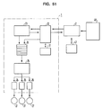
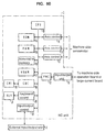
- Fig. 60 shows a block diagram of the main section of an NC (numerical control) unit, in which 1 is an NC unit, and 2 is an external input/output unit connected to the NC unit 1.
- the input/output unit 2 is for sending and receiving data used by the NC unit 1.
- the NC unit 1 comprises a processor (CPU) 10, ROM 14 and RAM 15 for storing a control program, a display unit (CRT) 19 and its controller (GDC) 18, a video RAM (VRAM) 17 for storing the data to be displayed, a keyboard (KEY) 21 and its controller 20, a nonvolatile memory (RAM for battery backup) 16 for storing various parameters and offset data, and axis control sections 11 for controlling each axis (X-axis, Y-axis and Z-axis) of a machine for machining a workpiece, a PMC unit 12 for transferring data to or from external units (a large-current board and console on a machine) by executing the predetermined sequential processing, and I/O unit 13, and an input/output controller 22 for transferring data to or from the external input/output unit 2.
- Each of elements 10, 11, 12, 14, 15, 16, 17, 18, 20 and 22 is connected by a busline 4.
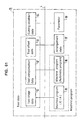
- Figure 61 shows a block diagram of various pieces of data which are stored in the nonvolatile RAM 16 of the NC unit 1.
- Tool data in the RAM 16 is comprised of elements 91, 92 and 93 and is set off by a dotted line in Figure 61.
- This tool data is data associated with a tool (not illustrated) mounted on a machine (not illustrated) to be controlled by the NC unit.
- tool shape data 91 is the data related to the shape of the tool
- tool compensation data 92 is the data relating to the nose-radius compensation value of a tool
- tool offset data 93 is the data for setting the offset value showing the mounting position of a tool.
- Cutting condition data 94 involves data for setting a value used for an automatic determination of the cutting condition.
- Machining program data consists of an area 95 for storing machining programs described by EIA language and an area 96 is for storing machining programs described by an automatic program.
- arrangement data 97 is included in the memory 16, and this data includes type-of-chuck data used for each machining operation and also includes data for a Z offset showing the end position of a workpiece.
- Parameter area 98 includes various parameters used for the NC unit 1.
- Figure 62 shows an operation board of an NC unit, which consists of a CRT 19 and a keyboard 21. The user operates the various keys on the keyboard 21 in order to input various data to the NC unit.
- the CRT 19 is used to display information to the operator.
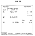
- Figures 63-66 show various pieces of data displayed on the CRT 19. Specifically, Figure 63 shows a "POSITION” screen showing the information for the present position, or the like, of a tool.
- Figure 64 is a "TOOL DATA” screen showing offset data for a tool.
- Figure 65 is an "NOSE-R" screen showing data for the nose radius of a tool.
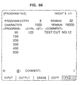
- Figure 66 is a "PROGRAM FILE” screen showing the information for the machining programs stored in the NC unit.
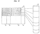
- Figure 67 is a diagram for explaining how data stored in the nonvolatile memory 16 is displayed on the CRT 19.
- numerical values in parentheses indicate rows and columns displayed on the CRT 19. That is, "-(5, 3)-" indicates the data displayed on the fifth row in the third column of the CRT 19.
- each piece of data is stored in the nonvolatile memory 16 of the NC unit 1 in a specific area according to the type of data. That is, one type of data, double-precision real-number type data (TYPE-L), is collected and stored in one part of the memory 16 as shown in the bottom portion of Figure 67.
- the numeral 28 represents this portion of the memory 16, specifically, the portion that includes TYPE-L data.
- another type of data double-precision integral-number type data (TYPE-N) is also collected and stored in another part of the memory as shown by the numeral 29 in the bottom part of Figure 67.
- each piece of data is usually stored in the nonvolatile memory 16 according to its data type and therefore data is not stored in a manner corresponding to the order in which it will be displayed on the CRT 19. Therefore, when data is to be displayed on the CRT 19, it must be rearranged first after it is read out of the memory 16 so that it may be arranged on the CRT 19 in order according to the numbers shown in parentheses in the top part of Figure 67. This rearranging operation takes time and thus limits the efficiency of the conventional NC unit.
- the data for an NC unit normally includes the following types: double-precision real-number type: 8-byte data capable of handling 15-digit real numbers; real-number type: 4-byte data capable of handling 7-digit real numbers; double-precision integral-number type: 4-byte data capable of handling 8-digit integers; and integral-number type: 2-byte data capable of handling 4-digit integers.
- double-precision real-number type 8-byte data capable of handling 15-digit real numbers
- real-number type 4-byte data capable of handling 7-digit real numbers
- double-precision integral-number type 4-byte data capable of handling 8-digit integers
- integral-number type 2-byte data capable of handling 4-digit integers.
- Data is conventionally transferred to or from an NC unit by an interface such as an RS232C interface.
- data is generally inputted or outputted in the form of character codes, since character codes can easily be inputted or outputted.
- the machining program 95, as well as compensation value data 92 or the parameter data 98 of the NC unit 1 is capable of being inputted and outputted to and from the NC unit 1 in the form of character codes, other data has conventionally not been input/output in the form of character codes.
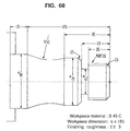
- FIG. 68 shows a machining diagram to be worked on according to the automatic machining program.
- Figure 69 shows the automatic program for machining the workpiece shown in Figure 68.
- the internal data of the automatic program shown in Figure 69 has a special data structure, which does not involve the use of character codes. Therefore, to input or output the automatic program data 96, the data stored in the NC unit 1 is directly inputted or outputted in a form which is not the character code form.
- the tool compensation value data 92 can be inputted or outputted in the form of character codes as shown below, (similarly to the EIA machining program 95).
- the tool compensation value 92 can be set or corrected by the command G10.
- a DNC function was used in order to transfer data between the NC unit 1 and the external input/output unit 2.
- the DNC function it is necessary to develop exclusive software for the NC unit 1 and external input/output unit 2 because data is inputted or outputted by using an exclusive protocol, such a protocol not involving the character code format.
- Figure 70 is a block diagram showing the outline of the processing by the program of the conventional NC unit 1.
- numeral 2 is the above-described external input/output unit which can be a controller for a floppy disk, IC card, and cassette tape or unit for communication with a computer system.
- Numeral 22 is an input/output controller in the NC unit 1
- 23 is a machining program analyzing section
- 24 is a data buffer
- 25 is a machine controlling section
- 26 is a servo controlling section
- 27 represents servomotors.
- a machining program is inputted from the external input/output unit 2 to the NC unit 1.
- the machining program may temporarily be stored in the memory 16 of the NC unit 1 or is directly sent to the analyzing section 23.
- the purpose of the machining program analyzing section 23 is to analyze the machining program and check for errors in the machining program and to send the analysis results to the data buffer 24.
- the data buffer 24 temporarily stores the analysis results of the machining program.
- the machining controlling section 25 sequentially fetches the analysis results from the data buffer 24 to control a machine according to the analysis results.
- an interpolation operation is executed, and the interpolation results are sent to the servo controlling section 26 where the servomotor 27 of each axis is servo controlled.
- the NC unit 1 can properly control a machine tool to machine a workpiece according to the machining program which has been input to the NC unit 1 by the input/output unit 2.
- a machining program may be generated, for example, by an off-line CAM (computer aided manufacturing) system or the like.
- measurement data involving a large number of commands of very short moving distances is generated because the machining program consists of data made by estimating a complex tool locus with microline segments. Therefore, in this instance, a great volume of data is transferred to the NC unit 1 by the input/output CAM system 2.
- the NC unit processing speed cannot match the speed at which the great volume of data is entering the NC unit.
- the program analyzing section 23 must first perform a specific analysis of the data before the analysis results can be sent to the data buffer 24.
- the machine controlling section 25 has sequentially processed all of the analysis results stored in the buffer 24 and the buffer is empty.
- the machine controlling section has no more data to fetch from the buffer and thus the machining operation temporarily stops. This affects a workpiece to be machined and also the machining time increases. Therefore, a method of transferring binary-format data as shown in Figure 71 is proposed in which tool moving distances of 4 msec and 8 msec are expressed by binary data to execute high-speed processing according to the moving-distance data for the specified number of axes.
- the number of axes to be commanded is specified by parameters.
- the data for one block consists of (2*N+1) bytes.
- N is the number of axes to be controlled.
- the moving distance of each axis is commanded with 2 bytes.
- a negative moving distance is commanded with the complement of 2.
- a check byte is obtained by adding the (2*N) bytes other than the check byte and discarding the overflow of 8 bits or more out of the total value.
- NC units 1 have the function of allowing data relating to a future machining operation to be input and set during actual machining. This is known as a background function since the operator is allowed to input and set data, for example, to be used in a future machining operation, while present actual machining is being carried out in the foreground.
- Certain types of data for example, tool compensation values and parameter values which affect the machining currently executed, however, cannot be corrected according to the background function. This is because it is dangerous to correct the data used for machining, such as parameters and tool information, during actual machining. Therefore, in the prior art, data to be corrected is restricted.
- an object of the present invention is to facilitate the processing of operation data in a numerical control unit.
- this object is achieved for a numerical control unit of the type outlined above in that the input means is adapted to input the memo data with respect to at least the operating data and related tolerance limits, the storage means is adapted to store the operation data according to a three-dimensional address with respect to display position and operation data type, and the display means displays the memo data in a format so that the memo data corresponding to each piece of operation data is uniquely specified through the three-dimensional address.
- the input means is adapted to input the memo data with respect to at least the operating data and related tolerance limits
- the storage means is adapted to store the operation data according to a three-dimensional address with respect to display position and operation data type
- the display means displays the memo data in a format so that the memo data corresponding to each piece of operation data is uniquely specified through the three-dimensional address.
- memo data it is possible to flexibly add information with respect to operation data such as operation limits according to necessity.
- Figure 1 is a block diagram showing a general construction of the NC unit according to the present invention.
- Figure 1 explains the input/output of data between an NC unit 1 and an external input/output unit 2.
- the unit 2 can be a paper tape reader, paper tape puncher, cassette, floppy disk drive, personal computer generally sold, or any one of input/output units capable of connecting with the NC unit.
- the input/output unit 2 generally uses an interface such as an RS232C. However, the interface is not restricted to the RS232C.
- Numeral 32 is an area where each piece of data in the NC unit 1 is stored, such data is normally stored in the nonvolatile memory 16 discussed above with respect to Figure 60.
- Numeral 33 represents data managed as a file for storing programs, such as machining programs or the like. These are also stored in the nonvolatile memory 16.
- Numeral 30 is a section for controlling the input/output of data between the NC unit 1 and the external input/output unit 2.
- a character-code converting section 31 is connected to the data input/output controlling section 30, and has the function of converting data which is in a form other than character code format into character codes.
- data which comes into the NC unit 1 by means of the external input/output unit 2 can be of character code format. That is, the converter 31 can convert the incoming character code format data into other forms of data, such as binary data, more easily handled by the NC unit 1. Also, when data is to be output from the NC unit 1 to the unit 2, the converting section 31 can convert data which is not of the character code format into the character code format before it is sent to the unit 2.
- the unit 2 finds the data very easy to handle if it is in the character code format, because any type of computer system can easily handle character code format (ASCII code). Further, with character code format data, a user of a PC is allowed to manipulate data in the NC unit very easily. Further, if a hard disk is located in the PC (external input/output unit 2) instead of inside of the numerical control unit 1, it is much cheaper to have the data be present in character code form.
- NC units use their own format of data. Therefore, a user would have to learn the new format of an NC unit if he purchases one which uses a different data format.
- the present invention due to the fact that all data is transformed into character code data before it is sent to the input/output unit 2, there is no longer a need to learn a format of data on a product-by-product basis.
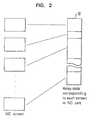
- the data in the area 32 of Figure 1 is stored in the memory 16 of Figure 60 according to an array-data format corresponding to each screen of the NC unit 1 which is displayed on the CRT 19, as shown in Figure 2.
- reference numeral 32 represents the data stored in the memory 16
- reference numeral 1 represents various NC screens which are displayed individually on a CRT 19.
- a specific area of the data 32 corresponds directly to each screen 1.
- Figure 4 shows an examples of how data 32 is stored in the memory 16 of the NC unit.
- the "TOOL DATA" shown in Figure 64 is shown stored as data 32 in Figure 4 according to the array data format of the invention.
- the data is considered as array data consisting of 10 rows and 3 columns and stored as internal data 32 according to the specific format shown in Figure 4.
- each screen data stored as data 32 consists of a header information part 5 and a data part 7.
- the header information part 5 consists of a screen number 1, the number 2 of rows, and the number 3 of columns of the array of the data part 7, and data type 4.
- the data type refers to the particular type of data involved; for example, in Figure 4 the data is designated in the header part as type L corresponding to double-precision real-number type data.
- screen numbers 1 may be used as index numbers for calling up particular data from the internal data 32 stored in the memory 16.
- screen numbers are used as index numbers for screens for the described embodiment, it is possible to use numbers according to the classification of screens. For example, it is possible to use “T1”, “T2”, “T3”...as screen numbers for a screen related to tool information and "P1", “P2”, “P3”...as screen numbers for a screen related to parameters.
- the screen number referenced by reference numeral 1 is indicated as screen no. 7 (see header section 5).
- the header 5 further specifies that there are 10 rows and 3 columns in the array format and that the data type is data type L.
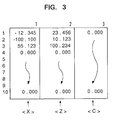
- Figure 3 further shows the array format as it would look displayed on the CRT 19. The total number of pieces of data in the data part can be obtained by multiplying the number of rows by the number of columns.
- Each piece of data is shown by a header including a screen number 1, number of rows 2, and number of columns 3.
- 7 indicates the screen number
- 3 indicates the row number
- 1 indicates the column number.
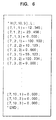
- the array data in Figure 4 is converted into the character codes shown in Figure 6, or the array data shown in Figure 4 is obtained by converting the character codes in Figure 6. Therefore, the NC unit can communicate with the external input/output unit 2 using strictly the character code format.
- each piece of data is thus uniquely specified by three coordinates. Since the type of data is also specified in the header, a software conversion, which is necessary in order to display the stored data on the screen, becomes easy. Specifically, a different type of software conversion is required based on the type of data. By specifying the data type in the header, the proper software can be used in order to convert, thus allowing for easy processing.
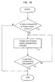
- the NC unit is also able to make certain corrections to data while other data is being operated on by the NC unit. That is, a user can indicate to the NC unit changes in data which the user wishes to make, such changes relating to a future use of the NC unit. For example, the user wishes to make a correction to data relating to a future machining operation to be carried out after the present machining operation. The user makes this correction to the future machining operation while a present machining operating is being carried out.
- the invention causes the screen 19 to be highlighted at the particular location at which the user wishes to make a correction, so as to provide for easy visualization of the correction location.
- the user pushes the program number for the next cutting program and the changes entered earlier by the user are automatically carried out at this time.
- the highlighting stays on so if the user has made a mistake in making changes, it is very easy to find.
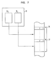
- Figure 8 shows a block diagram for showing the direction of data flow when an operator 39 edits data 32 in an NC unit 1 by operating an operation board 3 on the NC unit 1.
- the operator 39 edits data by operating a keyboard 21 while viewing the data displayed on a CRT 19 of the operation board 3.
- the data to be displayed on the CRT 19 is fetched out of the internal data 32 (Route 1000) and processed by a display preparing section 41 so that it can be displayed on the CRT 19 via Route 1001.
- the data inputted through the keyboard 21 by the operator 39 is sent to an editing section 40 via Route 1002. There, it is checked (at step 100 of the flow chart of Figure 9) to see whether editing of data is forbidden. Situations in which data editing is forbidden exist when it is dangerous to change the internal data 32, because the NC unit 1 is actually using the data while executing present machining, for example, according to an automatic operation program. If the editing of data is not forbidden, the internal data is directly edited (step 101 of Figure 9) by using Route 1003 of Figure 8. In this case, the contents of the internal data 32 are immediately changed according to the operator 39's wishes.
- the generated character codes are stored in the corrected-data storing area 38 via Route 1004 in Figure 8.
- the edited data part is highlighted on the screen (step 104) so that the corrected part can easily be recognized.
- the display controlling section 41 fetches the internal data 32 via Route 1000 and the corrected data 38 via Route 1005 and synthesizes these pieces of data to generate the data to be displayed on the CRT 19. That is, corrected results are displayed on the CRT 19.
- Figure 12 shows an example of the above-described procedure in which the data 123.456 at location X (column 1) of #5 (row 5) of the TOOL DATA screen is the new value after correction and 0 is the old value. Further, the data 456.789 at location Z (column 2) of #5 (row 5) is a new value and 0 is the old value before correction.
- the screen 51 of Figure 12 is the screen before data is corrected. There, it can be seen that the location X#5 and Z#5 are both 0.
- corrected data is highlighted as shown on the screen 53 to show that the data is temporarily corrected.
- the data is not actually changed in the data storage area 32 to the new values, but is only corrected on the screen for the user to observe. Once the NC unit finishes carrying out the present machining operation, the data will actually be changed in memory 32.
- Figure 10 is a flow chart for showing the processing for highlighting only the corrected data.
- the corrected data is taken out of the corrected data storing area 38 along Route 1006 of Figure 8 and sent to the changing section 42 which corrects the internal data 32 according to the corrected data (Route 1007). Then, the corrected data storing area automatically erases the data that was stored therein.
- the operator 39 is allowed to view on the CRT 19 the corrections which he wishes to make highlighted on the CRT 19 before the changes actually take place in the internal data area 32 during situations when data editing is forbidden. Once data editing is no longer forbidden, the corrected data storing area contents 38 are transferred to the internal data 32 by means of the changing section 42, thus completing the data correction operation.
- the corrected data part is highlighted on the display.
- any other method as long as the corrected part can be easily identified.
- the circuit shown in Figure 8 is capable of keeping track in a history data storing area 45 of all the data which has been corrected.
- the editing section 40 converts correction information into character codes whenever data is corrected and stores the character codes in the history data storing area 45 along Route 1012.
- the history data 45 is stored in the form of character codes with the same format as that of the corrected data 38, and the order of the data in the history data storing area 45 is such that data is stored in order of correction.
- the history data storing area 45 stores the data changes up to its assigned storage capacity. When the amount of data exceeds the storage capacity, data values are erased starting from the oldest one. Therefore, pieces of correction information from the latest to the oldest ones within the range of storage capacity are stored.
- the contents of the history data storing area 45 can be displayed on the CRT 19 along Route 1015. It is also possible to display data in order of storage or from the latest one, or to display special data, such as all correction data relating to a particular screen.
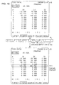
- Figure 15 shows examples of displaying the history data on the CRT 19.
- the screen A in Figure 15 shows an example of displaying data values starting with the latest one in order and the screen B in Figure 15 shows an example of displaying only the data in the screen 7.
- the menu display at the bottom of the screen is used to select a type of display operation for the history data 45, in which "ALL" is used to display pieces of the history data 45 from the latest one in order. It is also possible to display the data overflown from one screen onto another screen.
- the display of screen A in Figure 15 shows a numerical value of 1/5 displayed on the top right of the screen. This indicates the n-th screen of "m” screens.
- the screen A of Figure 15 shows that the numerical value indicates the first screen of five screens.
- "SORT" at the bottom of the screen B is another menu item and is used to display only special data, for example, as shown in screen B of Figure 15, special data such as only the corrected data related to the seventh screen can be displayed.
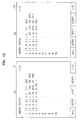
- the menu data "EDIT" is used to correct history data by placing the cursor 46 shown in Figure 16A on the incorrect data and making changes using the keyboard. Because editing makes it possible to change a value or erase data, it is possible to correct an erroneously corrected data value to a correct value and to erase corrected data when data which should not be corrected is erroneously corrected. It is also possible to generate the data for recovering corrected data by entering the data by means of keyboard 21. The data travels along Routes 1013 and 1014 to the history data storage area 45 where the history data may be directly edited.
- "COPY” is shown in Figure 16B and is also a part of the menu provided at the bottom of the screen. "COPY" is used to transfer some or all of the contents of the history data 45 to the corrected data area 38 along Route 1016. In this way, if corrected data is not present in the corrected data storing area 38, it can be placed there from the history data area 45 and then sent to the internal data area 32 for correction purposes. Thus, if at first changes have been made to a piece of data in area 32, and then additional changes are made to the same pieces of data at a later time, the original change will have been recorded by the history data area 45. This original change can be recovered by transferring the history data to the corrected data storing area 38 using the "COPY" function and then transferring this data to the internal storage area 32 for recovering the initial correction despite the fact that a second correction has been made.
- the data to be transferred can be specified as shown in Figure 16B by highlighting on the screen all of the history data which is desired to be transferred to the corrected data storing area 38.
- the range of data can be specified by specifying a block of data including the beginning and end of such a block to be copied with the cursor key on the keyboard 21. This is similar to a block function common in word processors. The chosen data is highlighted so that the operator can easily recognize it.
- the function "I/O" is also shown in the menu at the bottom of the screens in Figure 16. This function is used to input some or all pieces of history data from an external input/output unit 2 along Route 1017. Further, information from the history data area 45 can be output to the external input/output unit 2 by means of Route 1017. When the data is to be output from the history data area 45 to the external input/output unit 2, it is possible to specify the data to be outputted using the highlighting format similarly to the case described above for the "COPY" function.
- the operator When the operator is inputting information concerning corrections to be made to data, the operator can confirm each piece of data as it is being entered to make sure that he is entering the correct information.
- the internal data 32 is corrected according to the data stored in the corrected data storing area 38 similar to the above-described function, pieces of data may further be confirmed one by one by the operator before they are corrected.
- the correction method is described below according to the flow chart in Figure 11. It is first checked whether the corrected data storing area 38 contains any data (step 120). In this case, it is assumed that N indicates the number of corrected data values and n indicates a counter value for the corrected data. The counter value is set to "1" at step 121.
- the screen number S is initialized to "0" at step 122. It is assumed that S indicates a number of a screen to be displayed on the CRT 19.
- the screen number of the n-th data is compared with the value of S (step 123), in Figure 8, Route 1008 is used. If the n-th screen number is different from the value of S, the n-th screen number is taken out to set it to S (step 124). The screen with the screen number S is next displayed (step 125). The n-th data part is highlighted at step 126. The highlighted data indicates the data to be corrected. In this case, the highlighted data is the data before correction.
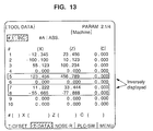
- the n-th data is displayed in the data inputting section (step 127) of the screen 61 as shown in Figure 14. That is, in Figure 14, screen 61 shows the data before correction for the screen number displayed. Row No. 5 is highlighted to indicate that this row is the one presently under correction. The values displayed, however, are the old values. The new values are displayed at the bottom of the screen in the data inputting section. That is, as shown at the bottom of the scrren 61 in Figure 14, the X value is to be changed from 0 to 123.456 and the Z value is to be changed from 0 to 456.789. The C value is not to be changed and therefore there is a blank pair of parentheses in the data inputting section for this value. In this state, the numerical control unit is waiting for the operator to confirm whether he actually wishes to make the change listed in the data inputting section of the screen 61. In Figure 8, Route 1009 corresponds to this state.
- Route 1010 is used to relate the operator 39's choice of input to the confirmation unit 43.
- the n-th data is corrected (step 129) by the correction section 42 in Figure 8. Routes 1011 and 1007 are used in Figure 8.
- the corrected data is then displayed on the screen (Route 1009) and this situation is shown in Figure 14 as screen 62.
- screen 62 shows, at row 5, that the value X has changed from 0 to 123.456, and the value Z has changed from 0 to 456.789.
- screen 62 shows that the next piece of corrected data is placed in the data inputting section of the screen at the bottom.
- This piece of data relates to the seventh row. Specifically, the value of X in the seventh row is to be changed from 0 to 111.111 and the value of Z is to be changed from 0 to 222.222. Row 7 is now highlighted and the numerical control unit is placed in a waiting state again, and the operator 39 must now decide whether he wishes to make the change to row 7 that is indicated in the data inputting section at the bottom of the screen.
- the highlighting is taken off (step 130) and the processing of the next data starts (step 131).
- step 132 When no more correction data to be processed remains, the entire processing is completed. If there is more correction data, processing is repeated starting with step 123 (step 132).
- the operator 39 can correct the internal data 32 while confirming pieces of corrected data 38 one by one.
- the operator corrects the internal data 32 in the NC unit 1, while reconfirming each piece of the data, it is possible to set the data editing forbidding mode before editing the data and correct the data while confirming each piece of the data in the data confirming mode after canceling the data editing forbidding mode. That is, the data correction in the internal data section 32 is not carried out until the data editing forbidding mode is removed. This prevents the harmful situation in which necessary data for a present machining operation is changed during machining.
- the data editing forbidding mode, data confirming mode and history storing mode may be turned on and off by operating the keyboard 21 of the operation board 3.
- the machining programs indicate to the numerical control unit which steps to go through in order to process the data relating to the machining operation.
- the invention allows the operator to edit the machining program while the program is being executed.
- a backup file is created for a file of data (which includes the machining program) to be corrected, and changes to the backup file may be made while the original file is being executed. In this way, there is no fear of erasing a file since there is always a backup, and corrections can be made to the backup file while the original is being executed, thus providing for efficient use of time.
- Figure 17 shows a general structure for explaining this embodiment.
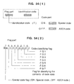
- numeral 70 is a directory table for managing the file data 33 shown in Figure 1. This file data is used for storing programs.
- Numeral 71 is the part of the directory table 70 for storing file names, 72 is for storing extension codes, 73 is for storing dates and times associated with the generating or updating of files and 74 is for storing other file managing information.
- the extension codes 72 are used to manage a plurality of files with the same file name. That is, a single file name can have more than one extension code.
- the extension code DAT relates to normal files which are the same as those conventionally used for the NC unit 1.
- Figure 66 shows an example of displaying file directory information.
- files are classified by file names and extension codes. Therefore, files with the same file name can be handled as different files when they have different extension codes.
- the present invention uses the above idea to manage the above files with the same file name by the application-side software using the conventional file management system.
- the extension codes 72 are classified into three types:
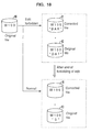
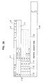
- Figure 18 is a diagram for explaining what happens to a file to be updated.
- the original file is shown by reference numeral 80. It has a file name of W100.
- W100 To correct the file with the file name W100, for example, a file with the file name W100 and the extension code 72 of BAK is prepared. Because the original W100 (DAT) remains as it is, W100 (BAK) can freely be corrected while normal program execution takes place with respect to file W100 having extension code DAT. If data editing is forbidden, the situation above occurs.
- W100 (BAK) is shown as reference numeral 81 in the Figure 18 for the situation where data editing is forbidden.
- the corrected file is stored by the name of W100 (DAT) (reference numeral 81 in the bottom dotted box of Figure 18) and the original file is stored by the name of W100 (OL1) (reference numeral 80 in the bottom dotted box of Figure 18).
- W100 DAT
- OL1 reference numeral 80 in the bottom dotted box of Figure 18
- the file W100 (BAK) generated under the data editing forbidding mode is corrected after the editing forbidding state is canceled and the corrected file is considered as a normal file (extension code DAT) and the original file is considered as an old file (extension code OLn).
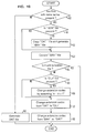
- Figure 19 is a flow chart of file operation showing the processing for correcting a file or reading file data from an external input/output unit 2.
- step 140 First it is checked if a file with the same file name 71 is present (step 140). If not, the file is stored by giving the extension code 72 of DAT to it (step 149). If so, it is checked if a file with the same file name 71 and the extension codes 72 of BAK is present (step 141). Hereafter, the embodiment will be described by assuming that the file name 71 handles the same file. If the BAK file is not present, the file with the extension code 72 of DAT is copied and handled as a file with the extension code 72 of BAK (step 142).
- step 142 is unnecessary in situations where file data is read from the external input/output unit 2 or with respect to a system in which all pieces of file data are temporarily transferred to a work area to edit the file and are corrected before being stored in the original file.
- the file with the extension codes 72 of BAK When the file with the extension codes 72 of BAK is present, it is capable of being continuously corrected by the operator. Specifically, the BAK file is not used until it becomes the file with the extension code DAT as described above with respect to Figure 18.
- the file with the extension code 72 of BAK is corrected at step 143 by the operator. Then, it is checked whether the file is under the data editing forbidding state (step 144). If so, the processing ends. In this case, the file with the extension code 72 of the BAK is left as it is. If not, it is checked if a file with the extension code 72 of OLn is present (step 145).
- OLn represents a file having an extension code 72 of OL1, OL2, OL3,...and OL9. If so, the value of n of each extension code is increased by 1 as follows: OL3 --> OL4 OL2 --> OL3 OL1 --> OL2
- a file with the extension code 72 of DAT is changed to a file with the extension code 71 of OL1 (step 147).
- a file with the extension code of BAK is changed to a file with the extension codes 72 of DAT (step 148).
- the corrected files (BAK) are entered as normal files (DAT).
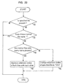
- step 135) it is checked if an OLn file is present. That is, it is checked whether there are old backup files existing. If not, file release processing ends because there is no old backup file to be released, and there is thus no problem with storing too many old files. If there are old backup files existing, the YES branch is taken from box 135 and it is checked at box 136 whether two or more OLn files with the same file name are present. If so, the file with the oldest generation date and time among the OLn files with the same file name is released (step 137). If not, the file with the oldest generation date and time among all OLn files is released (step 138).
- the file area is efficiently used by releasing unnecessary files according to necessity. That is, the present invention allows the original files to be stored as long as there is still room left in the file storage area so that the original file can be restored when necessary.
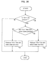
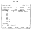
- Figure 21 shows a screen for showing the file directory display in the file recovery display mode. For this display mode, all files including old files (OLn files) are displayed unlike the example shown in Figure 66. Because the file names including extension codes 72 are displayed, it is possible to confirm all stored files to see which ones are there. In this case, when keyboarding a file name to be recovered, the file is recovered as explained in the flow chart of Figure 22.
- the file name includes extension codes 72 displayed in the ⁇ PROGRAM> column of the display screen of Figure 21. If not, the processing ends. If so, it is checked whether the specified file name belongs to a normal file (file with the extension code of DAT) at step 151. If so, the processing ends because it is unnecessary to recover the file. If the file name is specified for an old file (file with the extension code of OLn), it is checked if any other file with the same file name is present (step 152). For example, when W200.OL2 is specified, it is checked if a normal file with the extension code of W200.DAT is present.
- extension code of the normal file and that of the specified file are interchanged (step 153). If not, the extension code 72 of the specified file is changed to DAT (step 154). For example, when W200.OL2 is specified and W200.DAT is present, the extension codes 72 are changed as shown below. W200 (DAT) --> W200 (OL2) W200 (OL2) --> W200 (DAT)
- Some of the lengths of a workpiece may be defined as variables when the operator is defining the program which will be used to shape the workpiece. Since some of the workpiece lengths may be set as variables, there is no need to set a completely new program for a workpiece which differs only slightly from another workpiece. Instead, if the two workpieces differ by only one length, that length can be input as a variable length and assigned one value for the program for one workpiece and another value for the program for the other workpiece. This creates a great savings in time and memory.
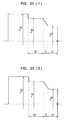
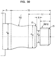
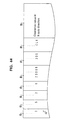
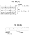
- Figure 23 (1) shows a machining diagram of a workpiece to be machined by a lathe.
- the horizontal axis in Figure 23 shows the Z-axis and the vertical axis shows the X-axis.
- the values are all predefined, for example, the lengths 20, 10 and 20 are specifically set forth in the Z-direction.
- the lengths LB and LA are defined as variables so that these Z-direction lengths may be altered by the operator.
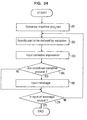
- the flow chart of Figure 24 explains the procedure for varying the lengths of two parts in the Z-axis direction, that is, to define the lengths of the parts LA and LB in Figure 23 (2) with variables.
- a machining program is prepared (step 201) similarly to the preparation of a normal machining program of the automatic machining program type.
- Figure 25 shows a screen in which the machining program prepared according to the machining diagram of Figure 23 (1) is displayed.
- the operator moves a cursor to the part of the screen to be defined by variables.
- the cursor When the cursor is brought to the desired position, the user selects the "VARIABLE DEFINE" box of the menu at the bottom of the screen in Figure 25, to select the function "VARIABLE DEFINE", so as to define the variable.
- An item in the menu is selected by pressing the menu key corresponding to the menu display.
- variable expression is then inputted by the operator as step 203.
- the variable expression is a mathematical expression consisting of variables, actual numerical values, and operators (+, -, *, /, etc.).
- LA is inputted at the position of the cursor 46. This would change the ending point Z designation from 20 (as shown in Figure 23 (1)) to LA (as shown in Figure 23 (2)).
- this value which was previously 20 is now defined as a variable.
- Step 204 checks as to whether any undefined variable is found in the just-inputted variable expression. If not, step 206 is executed. If a variable is undefined, an input message is sent to the operator at step 205, to indicate to the operator that at least one of the variables used in the operator's expression is undefined. Once all variables are defined, the processing ends at step 206, as long as there are no more lengths to be defined as variables by the operator. If there are more lengths to be defined as variables, control loops back to step 202 where the operator can move the cursor 46 to a new position. In this way, the operator is allowed to change various values (i.e., corresponding to workpiece lengths) of the machining program to variables, which may be assigned different values for different workpieces.
- Figure 26 shows the screen display after all variables are defined, in which the parts defined by variables are highlighted (d1 through d4).
- the original value serves as a default value of the part defined by each variable. Therefore, as shown in Figure 26, the highlighted values are the same as those shown in Figure 25 (which shows the screen before the variables have been defined).
- the function "ENTER" is selected in the menu in Figure 25.
- the part of the machining program to be entered is specified by the operator by moving the cursor 46.
- the range of the machining program to be entered is specified by moving the cursor 46 to the beginning of the part of the machining program to be entered, pressing the "INPUT” key, moving the cursor to the end of the part, and pressing the "INPUT” key again.
- the part 64 shown highlighted is the part to be changed, in accordance with the above description of Figures 25 and 26.
- a machining program with variables is entered together with a name and the entered machining program is called by that name.
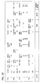
- Figure 28 shows the data structure of a machine program entered according to the above procedure.
- t1 is a name added by the operator for entry, indicating that "BAR_TP16" is defined.
- the block t4 is the number of variables used, indicating in this case that two variables are used, LA and LB.
- t5 is the number of parts defined by variables, indicating in this case that there are four parts defined by variables, d1 through d4.
- Alphanumeric t10 specifies the names of the variables, indicating here that there are two variables, and that the names LA and LB are used; t11 indicates the message data of each variable, indicating that the following messages correspond to the following variables.
- t15 shown in Figure 28 is the variable expression defined by each part.
- t16 represents the highlighted portion 64, for example, of the screen shown in Figure 27 which includes the original machining program before it is replaced with variables. The original machining program is directly stored so that it can be later retrieved if necessary.
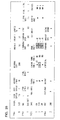
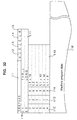
- Figure 32 shows the data structure of the example shown in Figure 31.
- the data structure has the same format as explained above with respect to Figure 28.
- Each group variable has a plurality of values assigned to it, such values being the common values which the operator will most likely want to assign to the variable.
- the operator is thus able to select from a group of possible values to be assigned to the group variable, and therefore the user does not have to come up with the value of the variable himself.
- Many basic machining patterns are pre-registered, i.e., the values for a group variable which will lead to commonly machined workpieces are defined beforehand. The operator can look at the screen and see the pre-registered patterns and select one. This will be described specifically below.
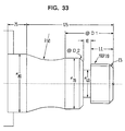
- variable LL is a regular variable, such as described above with respect to Figures 23-32.
- Figure 34 shows a machining program made by defining the machining program in Figure 33 by variables. Variables having an "@" at the beginning indicate group variables.
- Figure 35 shows a screen for defining the group variables used. First, the non-group variables are defined as discussed above with respect to Figures 23-32. Then, the operator selects "GROUP" in the menu in Figure 25. This indicates to the numerical control unit that the operator is now going to define group variables. In Figure 35, t17 indicates a group variable name, i.e., @D1. t18 indicates a group name.
- the operator when the operator selects the group TP3, the operator is actually specifying that the variable @D1 is to be 80 and the variable @D2 is to be 5.
- the operator selects group TP3, the operator is selecting a common predetermined machining operation. In this way, the user does not have to know that one variable being 80 and the other variable being 5 will give a common machining operation. All the operator has to do is select the group TP3 and the numerical control unit will automatically assign the values 80 and 5 to the group variables @D1 and @D2, respectively.
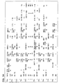
- Figure 36 shows the data structure of Figure 34, in which t2 is the number of group variables used and t3 is the number of groups involved.
- the number of group variables is 2 (@D1 and @D2) and the number of groups is 5 (TP1 through TP4).
- t6 is a group variable name
- t7 is a group name
- t8 is the value of the group variable @D1 in each group
- t9 is the value of the group variable @D2 in each group.
- the other indicators in Figure 36 are the same as those described with respect to Figure 32.
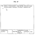
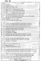
- Figure 37 shows a screen display for defining a machining program.
- a normal machining program can be defined by inputting data through the keyboard 21 and the machining program shown in Figure 43 is obtained by programming the machining diagram shown in Figure 68.
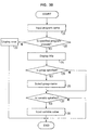
- FIG 38 is a flow chart showing the processing for defining a variable-type machining program.
- a program name is inputted at step 211.
- the title of the specified program is displayed at step 214.
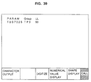
- Figure 39 shows an example of displaying a title "TBS7025”.
- the display "PARAM” represents a variable-type machining program and the program name (title) is displayed under "PARAM”.
- "GROUP" for defining the group names is displayed and non-group variable "LL” is also displayed.
- step 215 it is checked at step 215 whether the operator has specified a particular group name (one of TP1 through TP5 shown in Figure 35). The operator would select a particular group name based on which of a group of common machining operations the user wishes to have performed. If a group name is specified, the group is selected at step 216. Figure 39 shows that TP3 is selected by the operator. Then, at step 217, it is checked whether the operator has inputted a value for the non-group variable LL. If the operator has inputted a value, the value is inputted at step 218. When the value is inputted, the variable name (LL) is displayed and a message corresponding to each variable is also displayed on the screen. For example, when LL is displayed, the message defined by T11 in Figure 36 is displayed as "THR_L" (not shown in Figure 39). Therefore, the operator is able to confirm that the particular variable he has entered is the correct one.
- a particular group name one of TP1 through TP5 shown in Figure 35. The operator would
- the graphic display of a configuration can be displayed with a default value without defining a variable value. Therefore, to call a variable-type machining program, it is possible to prepare a function for helping the operator in which the configurations of a plurality of entered variable-type machining programs are simultaneously displayed on the screen so the operator can select a desired variable-type machining program.
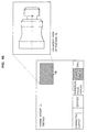
- variable part of the variable-type machining program defined in Figure 39 is converted into an actual value and displayed.
- Figure 41 shows an example of converting and displaying the values defined in Figure 39. In this case, the parts defined by variables are highlighted.
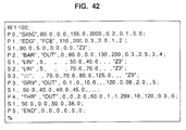
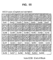
- Automatic-program data is transferred to or from an external input/output unit 2 in the form of character codes.
- Each piece of data is separated by a comma for each row of the automatic program as shown in Figure 42.
- the data to be outputted is the same as the data to be displayed on the screen. Therefore, the operator is able to clearly see the complete machining program on the screen. Further, there is no need for any conversion of the program data before it is sent out from the NC unit 1 to the external input/output unit 2.
- Automatic program data includes a part where it is unnecessary to set data. Only a comma is added to these parts as shown in Figure 42.
- an automatic program uses a symbol such as a triangle mark showing surface roughness which cannot be expressed by character codes, such marks are substituted by predetermined character codes (for example, "Z3").
- the position of each piece of automatic program data can be specified by the process number t12, sequence number t13 and data position t14 as shown in Figure 32. Therefore, a machining program can be inputted or outputted according to the format (character codes) shown in Figures 42 and 43 similarly to the processing of the internal data 32 described above.
- Memo data relating to each piece of data stored in the NC unit 1 can be entered by the operator and displayed on the screen 19.
- the memo data includes data relating to the tolerance limits of each piece of data, a standard set value to which the data is usually set, a display symbol representing that piece of data, and a display message corresponding to each piece of data.
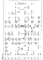
- Memo data is set by the operator by inputting data to the table shown in Figure 44 through the keyboard 21 when the table is displayed on the CRT 19.
- the data input position is specified by the operator by operating the cursor key 46 on the keyboard 21.
- numeral 82 indicates a screen number
- 83 indicates a row number
- 84 indicates a column number.
- the corresponding data is uniquely specified by the numerals 82 through 84.
- Numeral 85 indicates the lower limit of the setting tolerance for a particular piece of NC data and 86 indicates the upper limit.
- Numeral 87 specifies the standard set value
- 88 specifies a symbol for displaying the corresponding data on the CRT 19
- 89 specifies a message to be displayed on the CRT 19 when inputting the corresponding data.
- the memo data of the data at the fifth row and second column on the third screen is specified.
- the data setting tolerance limits range between 0 and 20000 and the standard set value is 300.
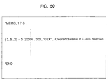
- the data is expressed by the symbol CLX on the CRT 19. This specific piece of NC data identified by the symbol CLX relates to the clearance value in the X-axis direction, as indicated by the message at reference numeral 89 in Figure 44.
- Figure 46 shows a flow chart for resetting all pieces of data which have been set according to the memo data format discussed above, with the standard set value. This is especially useful in situations when data is lost due to, for example, a power failure.
- step 401 it is checked if memo data is specified at step 401.
- This step makes sure that all data being reset to the standard value is data which has been previously assigned values according to the memo data format of Figure 44.
- a variable N is initialized to "1" at step 402.
- the variable N is used as an index. That is, N assumes the value of "1" at first, and this corresponds to the first piece of memo data. Then, the values of N will be increased by "1" so that it assumes the value "2", thus representing the second piece of memo data. This repeats until N achieves the value of NMAX, representing the last piece of memo data.
- the N-th piece of memo data is extracted at step 403.
- the standard value 87 is set to the corresponding data positions at step 404 which are shown by numerals 82 through 84 in Figure 44.
- the value of N is increased by "1" at step 405.
- NMAX indicates the total number of pieces of memo data being reset to the standard value. If some pieces of memo data are left, the operation is repeated starting with step 403.
- the standard value 87 can be set to all pieces of data specified by the memo data format of Figure 44.
- step 411 it is checked at step 411 whether memo data corresponding to the screen to be displayed is present. If so, display positions 83 and 84 and symbol 88 are extracted at step 412 from the corresponding memo data of Figure 44. The symbol 88 is displayed at the display positions 83 and 84 at step 413. If there is more data left to be displayed, steps 412 and 413 are repeated by means of a decision taking place at step 414.
- the above-described operation displays the symbol indicated at position 88 of Figure 44 at the position indicated by the row number 83 and the column number 84.
- the symbol CLX is displayed at the position of the fifth row and the second column as shown in Figure 45 by reference numeral 75. From the example in Figure 45, it is clear that the data at the position of "5,2" has the value of 1520. The symbol is used instead of a number to display data so that the meaning of the data will easily be understood by the operator.
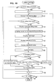
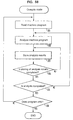
- Figure 48 is a flow chart showing the processing for setting the data in the NC unit 1.
- a cursor 46 is placed at the position corresponding to the row and column number desired by the user.
- numeral 46 represents the cursor and the position of the cursor on the data is extracted.
- the cursor is located at the fifth row and second column.
- any memo data corresponding to the cursor position is present at step 422.
- Such memo data would correspond to data previously input by an operator.
- the memo data represents data corresponding to the third screen, therefore, it is checked if the data at the fifth row and second column in the third screen is set to the memo data format of Figure 44. If no corresponding data is present, the data is directly keyboarded by the operator at step 423 and the keyboarded data is directly stored in a memory at step 433. That is, if no memo data presently exists for the particular NC data involved, the operation consists of merely keyboarding the operator-desired data and the keyboarded data is stored in a memory.
- any corresponding data is present, that is, if any previously entered data is present, it is extracted from the memo data at step 424.
- a message is displayed on the screen of the CRT 19 by using the message data 89 of the extracted data.
- the message data "clearance value in the X-axis direction" is stored, it is displayed on the screen of the CRT 19 as shown by the numeral 76 in Figure 45. Therefore, the operator can clearly understand the significance of the data being set.
- the tolerance limits are displayed on the screen of the CRT 19 by using the tolerance limits 85 and 86 of the extracted data at step 426.
- the tolerance limits are displayed as shown by the numeral 77 in Figure 45.
- the standard value is displayed on the screen of the CRT 19 by using the standard value 87 of the extracted data at step 427.
- Numeral 78 in Figure 45 indicates the displayed value.
- the operator inputs set data.
- Figure 49 is a flow chart for checking whether the data stored in memory is within the set tolerance limits. First, it is checked if any memo data is stored at step 441. If not, the processing ends. If some memo data is stored, a value of "1" is set to the index variable N at step 442. The N-th piece of memo data is extracted at step 443 to check if the data value at the specified positions 82 through 84 of the memo data are kept within the tolerance limits 85 and 86 of the memo data at step 444. If so, the next data is checked at step 456. If not, the processing for resetting data is started because the set data in the memory is incorrect.
- a corresponding data screen is displayed at step 445.
- This corresponding data screen is a screen displayed with the screen number 82 of the memo data.
- the cursor 46 is displayed at the position indicated by the row number 83 and the column number 84 of the memo data at step 446.
- a message is displayed at step 447, tolerance limits are displayed at step 448, a standard value is displayed at step 449, and data is inputted again at step 450.
- the standard value is used as the inputted data at steps 451 and 452.
- step 453 the data which he has inputted is checked at step 453 in order to determine whether it is within the tolerance limits. If it is not, an error is displayed at step 454 and control loops back to step 450 so that the operator can input data again.
- the inputted data is stored in the memory at step 455.
- the value of N is increased by "1" at step 456 to check if the value of N exceeds NMAX at step 457. If not, the next memo data is checked by repeating the operation starting with step 443.
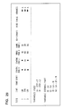
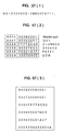
- the contents of memo data can be transferred to or from the external input/output unit 2 by converting them into the following character codes. In this way, it is possible to easily display and edit the contents of the memo data by an external system.
- the three numerical values in parentheses indicate the screen number 82, row number 83 and column number 84.
- the tolerance lower limit 85, the tolerance upper limit 86, the standard value 87, the symbol 88, and the message 89 are converted into character codes in order. Because 85 through 87 are numerical data, they are converted into decimal numbers. Because 88 and 89 are character data, they are converted by enclosing them with double quotation marks. A comma is put between pieces of data.
- Figure 50 shows memo data outputted in the form of character codes.
- the terminology “*MEMO, 176;” at the beginning of the data indicates that the data is memo data, and the number “176" indicates the number of pieces of memo data total.
- the terminology “*END;” indicates the end of data.
- the corresponding data is indicated by the screen number 82, row number 83 and column number 84. However, it is possible to indicate the data by another method.
- the output format of memo data is not restricted to the format of Figure 50.
- the input program is analyzed by an analysis circuit inside of the NC unit and the analyzed output is stored in a buffer.
- the output of the buffer is sent to a machining control section for controlling the motors of a tool to shape a workpiece. If the buffer becomes empty, machining stops. In situations where the program is complicated and movements are small, the instructions can be exhausted from the buffer faster than the analysis section can keep up. Therefore, the machining will often stop, causing cumbersome operation.
- the CAM system uses circular interpolation so that a curve results in a series of small lines and each line requires an instruction that takes a predetermined amount of time to execute. Since there is so much information present, the analysis system cannot keep up with the buffer and the buffer eventually sends all of its data out while the analysis section is still processing the data relating to the tiny lines making up the curve.
- the CAM system (external input/output unit 2) sends program data to the NC unit 1 and the data is stored in the NC unit 1. This data is later readout to the buffer without going through the analysis section. In situations where much data is present, the data can be read in straight from the CAM system to the buffer of the NC unit without storing it in the NC unit. The data is fed into the buffer using binary conversion. The data is sent in from the CAM system in character data format. Conversion to binary is performed in the NC unit by software. Data coming from the CAM system, in this case, is approximately equal to the data that would come through the analyzer. The advantage to not using the analyzer is that less memory is required and better control is obtained. The details will now be explained with respect to Figures 51 through 59.
- Figure 51 is a block diagram showing the outline of the machining program processing of the NC unit 1 according to the present invention.
- numeral 47 is an external memory such as a floppy disk or hard disk.
- Numeral 48 is an off-line CAM system or the like.
- the normal processing is the same as the processing according to the prior art in Figure 70 except for the fact that the data in the data buffer 24 is stored according to the format shown in Figure 52 (1).
- the header part consists of one piece of 6-byte data, in which the information for indicating the type of the block data is stored.
- the data part consists of 30 pieces of 6-byte data, each piece (see Figure 52 (2)) consisting of a code part (2 bytes) and a data part (4 bytes).
- the header part also consists of a code part (2 bytes) and a data part (4 bytes).
- the two-byte code part of the data part consists of a one-byte flag part and a one-byte identification code as shown in Figure 54 (1).
- the configuration of the flag part is shown in Figure 54 (2).
- the flag part classifies the identification code into ASCII code or special code and the data contents in the code part. When the most significant bit of the flag part is on, it indicates that the identification code is a special code. When the most significant bit is off, it indicates that the identification code is an ASCII code.
- Figure 55 shows an ASCII code list and Figure 56 shows a special code list. For example, when the analysis result shown in Figure 57 (1) is obtained, the data in Figure 57 (2) is generated.
- the invention not only analyzes a machining program and controls a machine tool according to the analysis results but has a compile mode function.
- the compile mode function is a method for storing analysis results of a machining program in a memory area and directly using the data in the memory area when actually controlling a machine.
- Figure 58 is a flow chart showing a compile method.
- a machining program is read out at step 301.
- the machining program can be read out of the memory 16 in the NC unit 1 or received while being input through an input/output control unit 22 in the NC unit 1.
- the machining program is analyzed at step 302. This analysis takes place by means of the analysis section 23.
- the output of the analysis section 23 is sent back to the input/output control unit 22 for storage.
- the analysis results are stored in a memory area at step 303. It is possible to store the results in the internal memory (15 or 16) of the NC unit 1 if it has an adequate memory area capacity, or in the external memory 47 through the input/output control unit 22.
- step 304 When storing of data is completed (this is checked at step 304), it is further checked at step 305 whether analysis is completed. If so, it is checked whether the program analysis is completed at step 306. If so, the processing ends. Thus, all analysis results of the machining program are stored in the memory area at this point.
- step 311 it is checked whether any compiled data is present at step 311. If so, it is checked if any data not transferred to the data buffer 24 is left in the data for the machining program analysis results. If so, it is checked if any space is present in the data buffer 24 at step 312. If the data buffer 24 can only store the data for one block, it is checked if the contents of the buffer is already filled. When the data buffer can store the data for more than one block, it is checked whether previously used data or an empty area is present. If any space is present in the buffer, compiled data is inputted at step 313.
- Compiled data is inputted by reading the data for one block out of the memory area storing the analysis results of a machining program as shown in Figure 58.
- the data stored in the internal memory 15 or 16 of the NC unit 1 or external memory 47 is read.
- the CAM system 48 can generate the data identical to the analysis results according to the present invention, it is also possible to read the data from the input/output control unit 22 directly through the external input/output unit 2.
- the data is generated by the CAM system 48 is to be used, it is also possible to read the data when necessary by storing it in the external memory 47.
- the compiled data is normally binary data according to the data format shown in Figure 57 (2). However, to output the data to an external unit from the NC unit 1, it is possible to output it in the form of ASCII codes expressing binary codes by hexa-codes as shown in Figure 57 (3).
- Figure 57 (3) the last symbol ";" indicates the end of the data for one block and the numeral 48 before the symbol indicates the value of the check sum obtained by summing all of the hexa-codes for each byte before the numeral 48.
- the value of "0 x 80 + 0 x 04 + ....+ 0 x 00" is expressed as "0 x 648". Therefore, "48" which is the low-order two digits of "648" is determined as the check sum.
- the character-code converting section 31 in Figure 51 outputs the analysis result shown in Figure 57 (2) by converting them into the character codes shown in Figure 57 (3).
- the analysis results of a machining program in the form of the binary data shown in Figure 57 (2) or the character codes shown in Figure 57 (3).
- the inputted compiled data consists of ASCII codes, it is converted into binary codes by the character-code converting section 31 at step 315 and stored in the data buffer 24 at step 316.
- the analysis results of the stored machining program are sequentially read out and stored in the buffer 24.
- the machine controlling section 25 reads the data, according to its normal processing operation, to control a machine. In this case, because it is unnecessary to use the machining program analyzing section 23 during real-time machining, no time is required for machining program analysis while the machining is taking place. Further, there is no danger that there will be no more data left in the data buffer 24, therefore, the machining will not stop unexpectedly.
- the format of the machining program analysis results uses the format shown in Figures 52 through 57.
- the format is not restricted to that in Figures 52 through 57.
- the output format is not restricted to that in Figure 57 (3). It is possible to change the format according to necessity.
- the above-described embodiment of the present invention makes it possible to directly input the analysis results of a machining program. Therefore, the analysis time of the machining program is unnecessary and high-speed processing is realized. Thus, this embodiment can execute machining including continuous micro-blocks and requiring a high feed speed which cannot be executed by the conventional NC unit.
Description
- The present invention relates to a numerical control unit, comprising storage means adapted to store operation data, input means adapted to input memo data with respect to operation data, and display for displaying the memo data.
- Such a system is known from EP-0 372 086 describing a setting method of NC output data. According to this document NC output data is expressed by characters or symbols. The format is inputted through an operation panel using characters or symbols which are converted into internal codes by use of a table stored in a RAM memory.
- In addition, in "Language Reference DBaseIV", ASHTON-TATE, 1988 XP002028896 there is described an approach to create custom forms for the data input/output to data base files.
- Further,
GB 2 273 911 A describes a data processing system for a general purpose computer, wherein a table comprising a plurality of data cells is initialized and subsequently editing in each cell is performed individually according to management data stored in a table cell management data memory. - Still further, EP-
A-0 428 505 A2 describes a control apparatus intended primarily for the control of hemodialysis, i.e. the purification of the blood of patients with deminished renal function. Here, this control apparatus is particularily implementing an invariant range to avoid the entrance of critical control constants. - Still further, in US-A-4 402 057 there is proposed a method and apparatus for ensuring correct operation of a microcomputer in the event of a power outage.
- Finally, in Patent Abstracts of Japan, vol. 11, no. 391 (P-649) and GB-A-62 166 767 it is proposed to simplify a complicated memo control by providing a memo describing function into a document and omitting the need to produce a comment required in a document production process for another document.
- A conventional numerical control unit will now be described in accordance with Figs. 60-71.
- Fig. 60 shows a block diagram of the main section of an NC (numerical control) unit, in which 1 is an NC unit, and 2 is an external input/output unit connected to the
NC unit 1. The input/output unit 2 is for sending and receiving data used by theNC unit 1. TheNC unit 1 comprises a processor (CPU) 10,ROM 14 andRAM 15 for storing a control program, a display unit (CRT) 19 and its controller (GDC) 18, a video RAM (VRAM) 17 for storing the data to be displayed, a keyboard (KEY) 21 and itscontroller 20, a nonvolatile memory (RAM for battery backup) 16 for storing various parameters and offset data, andaxis control sections 11 for controlling each axis (X-axis, Y-axis and Z-axis) of a machine for machining a workpiece, aPMC unit 12 for transferring data to or from external units (a large-current board and console on a machine) by executing the predetermined sequential processing, and I/O unit 13, and an input/output controller 22 for transferring data to or from the external input/output unit 2. Each ofelements busline 4. - Figure 61 shows a block diagram of various pieces of data which are stored in the
nonvolatile RAM 16 of theNC unit 1. Tool data in theRAM 16 is comprised ofelements tool shape data 91 is the data related to the shape of the tool,tool compensation data 92 is the data relating to the nose-radius compensation value of a tool, andtool offset data 93 is the data for setting the offset value showing the mounting position of a tool.Cutting condition data 94 involves data for setting a value used for an automatic determination of the cutting condition. - The dotted line in Figure 61 surrounding
elements area 95 for storing machining programs described by EIA language and anarea 96 is for storing machining programs described by an automatic program. - Further,
arrangement data 97 is included in thememory 16, and this data includes type-of-chuck data used for each machining operation and also includes data for a Z offset showing the end position of a workpiece.Parameter area 98 includes various parameters used for theNC unit 1. - Of all the data stored in the
RAM 16 described above in the conventional NC unit, only the EIAmachining program 95 is stored in the form of character codes (ASCII). The other data is stored in other various forms, such as binary form. - Figure 62 shows an operation board of an NC unit, which consists of a
CRT 19 and akeyboard 21. The user operates the various keys on thekeyboard 21 in order to input various data to the NC unit. The CRT 19 is used to display information to the operator. Figures 63-66 show various pieces of data displayed on theCRT 19. Specifically, Figure 63 shows a "POSITION" screen showing the information for the present position, or the like, of a tool. Figure 64 is a "TOOL DATA" screen showing offset data for a tool. Figure 65 is an "NOSE-R" screen showing data for the nose radius of a tool. Finally, Figure 66 is a "PROGRAM FILE" screen showing the information for the machining programs stored in the NC unit. - Figure 67 is a diagram for explaining how data stored in the
nonvolatile memory 16 is displayed on theCRT 19. In Figure 67, it is assumed that numerical values in parentheses indicate rows and columns displayed on theCRT 19. That is, "-(5, 3)-" indicates the data displayed on the fifth row in the third column of the CRT 19. - In general, each piece of data is stored in the
nonvolatile memory 16 of theNC unit 1 in a specific area according to the type of data. That is, one type of data, double-precision real-number type data (TYPE-L), is collected and stored in one part of thememory 16 as shown in the bottom portion of Figure 67. Thenumeral 28 represents this portion of thememory 16, specifically, the portion that includes TYPE-L data. As another example, another type of data, double-precision integral-number type data (TYPE-N) is also collected and stored in another part of the memory as shown by thenumeral 29 in the bottom part of Figure 67. - Therefore, in the conventional NC unit, each piece of data is usually stored in the
nonvolatile memory 16 according to its data type and therefore data is not stored in a manner corresponding to the order in which it will be displayed on theCRT 19. Therefore, when data is to be displayed on theCRT 19, it must be rearranged first after it is read out of thememory 16 so that it may be arranged on theCRT 19 in order according to the numbers shown in parentheses in the top part of Figure 67. This rearranging operation takes time and thus limits the efficiency of the conventional NC unit. - The data for an NC unit normally includes the following types: double-precision real-number type: 8-byte data capable of handling 15-digit real numbers; real-number type: 4-byte data capable of handling 7-digit real numbers; double-precision integral-number type: 4-byte data capable of handling 8-digit integers; and integral-number type: 2-byte data capable of handling 4-digit integers. Thus, with the conventional NC unit, much rearranging of data needs to be performed in order to display the data on the
CRT 19. - Data is conventionally transferred to or from an NC unit by an interface such as an RS232C interface. For the EIA
machining program 95 discussed earlier, data is generally inputted or outputted in the form of character codes, since character codes can easily be inputted or outputted. Although themachining program 95, as well ascompensation value data 92 or theparameter data 98 of theNC unit 1, is capable of being inputted and outputted to and from theNC unit 1 in the form of character codes, other data has conventionally not been input/output in the form of character codes. - Recently, an NC unit has been developed in which automatic ("canned") machining programs 96 (Figure 61) are increasingly used, these programs being stored in the non-volatile
RAM 16. Figure 68 shows a machining diagram to be worked on according to the automatic machining program. Figure 69 shows the automatic program for machining the workpiece shown in Figure 68. The internal data of the automatic program shown in Figure 69 has a special data structure, which does not involve the use of character codes. Therefore, to input or output theautomatic program data 96, the data stored in theNC unit 1 is directly inputted or outputted in a form which is not the character code form. - Therefore, a problem existed in the prior art in that only certain types of data were inputted to or outputted from the
NC unit 1 in the form of character codes which are easily handled by the external input/output unit 2. - The manner in which the restricted class of data is input/output to/from the
NC unit 1 in the form of character codes will now be described. For example, the toolcompensation value data 92 can be inputted or outputted in the form of character codes as shown below, (similarly to the EIA machining program 95).
G01L11 P_X_Z_Y_R_Q;
where, - P: is the offset number
- X_: is the X-axis offset value
- Z_: is the Z-axis offset value
- Y_: is the Y-axis offset value
- R_: is the nose radius compensation value
- Q_: is the assumed tip position
-
- The
tool compensation value 92 can be set or corrected by the command G10. - An example will now be given of how the
parameter data 98 can be inputted or outputted in the form of character codes.
G10L50: - N_R_; where,
- N_: is the parameter number
- P_: is the axis number (for axis-type parameter)
- R_: is the parameter value.
-
- In conventional NC units, a DNC function was used in order to transfer data between the
NC unit 1 and the external input/output unit 2. However, according to the DNC function, it is necessary to develop exclusive software for theNC unit 1 and external input/output unit 2 because data is inputted or outputted by using an exclusive protocol, such a protocol not involving the character code format. - Now, the conventional method of processing data using a machining program will be described. Figure 70 is a block diagram showing the outline of the processing by the program of the
conventional NC unit 1. In Figure 70,numeral 2 is the above-described external input/output unit which can be a controller for a floppy disk, IC card, and cassette tape or unit for communication with a computer system.Numeral 22 is an input/output controller in theNC unit - A machining program is inputted from the external input/
output unit 2 to theNC unit 1. The machining program may temporarily be stored in thememory 16 of theNC unit 1 or is directly sent to the analyzingsection 23. - The purpose of the machining
program analyzing section 23 is to analyze the machining program and check for errors in the machining program and to send the analysis results to thedata buffer 24. Thedata buffer 24 temporarily stores the analysis results of the machining program. Themachining controlling section 25 sequentially fetches the analysis results from thedata buffer 24 to control a machine according to the analysis results. In themachine controlling section 25, an interpolation operation is executed, and the interpolation results are sent to theservo controlling section 26 where theservomotor 27 of each axis is servo controlled. In this way, theNC unit 1 can properly control a machine tool to machine a workpiece according to the machining program which has been input to theNC unit 1 by the input/output unit 2. - When the NC control unit is to machine a die for use in molding, a machining program may be generated, for example, by an off-line CAM (computer aided manufacturing) system or the like. In this case, measurement data involving a large number of commands of very short moving distances is generated because the machining program consists of data made by estimating a complex tool locus with microline segments. Therefore, in this instance, a great volume of data is transferred to the
NC unit 1 by the input/output CAM system 2. The NC unit processing speed cannot match the speed at which the great volume of data is entering the NC unit. - Specifically, the
program analyzing section 23 must first perform a specific analysis of the data before the analysis results can be sent to thedata buffer 24. In the meantime, themachine controlling section 25 has sequentially processed all of the analysis results stored in thebuffer 24 and the buffer is empty. When the buffer becomes empty, the machine controlling section has no more data to fetch from the buffer and thus the machining operation temporarily stops. This affects a workpiece to be machined and also the machining time increases. Therefore, a method of transferring binary-format data as shown in Figure 71 is proposed in which tool moving distances of 4 msec and 8 msec are expressed by binary data to execute high-speed processing according to the moving-distance data for the specified number of axes. The number of axes to be commanded is specified by parameters. - According to the conventional method of Figure 71, the data for one block consists of (2*N+1) bytes. N is the number of axes to be controlled. The moving distance of each axis is commanded with 2 bytes. A negative moving distance is commanded with the complement of 2. A check byte is obtained by adding the (2*N) bytes other than the check byte and discarding the overflow of 8 bits or more out of the total value.
- Also, another method of realizing high-speed processing by limiting the format of a machining program inputted from an
external unit 2 has been proposed in which a high-speed block can be commanded in the machining program. Only the following factors can be specified in this block: - X: the moving distance of the X-axis
- Y: the moving distance of the Y-axis
- Z: the moving distance of the Z-axis
- F: the cutting (feed) speed
-
- All pieces of data in this block are processed through linear interpolation (G01). A command format is specified as follows:
- G05P01: ---start of high-speed machining
- X_Y_Z:
- G05P00: ---end of high-speed machining.
-
- According to these conventional methods, however, the number of factors which can be specified in the blocks are limited (see Figure 71). Further, the complicated process of linear interpolation must be carried out.
- Another problem which existed in the prior art NC units will now be discussed. Some
NC units 1 have the function of allowing data relating to a future machining operation to be input and set during actual machining. This is known as a background function since the operator is allowed to input and set data, for example, to be used in a future machining operation, while present actual machining is being carried out in the foreground. Certain types of data, for example, tool compensation values and parameter values which affect the machining currently executed, however, cannot be corrected according to the background function. This is because it is dangerous to correct the data used for machining, such as parameters and tool information, during actual machining. Therefore, in the prior art, data to be corrected is restricted. - However, when it is necessary to correct internal data which relates to a future process, the data is conventionally corrected after the present machining is completed. Thus, a problem exists in that a subsequent machining operation cannot be executed during correction of data and thus downtime increases.
- To solve this problem, a method involving two memories is proposed in Japanese Utility Model Laid-open No. 1-127002. For this method, however, double memory area is necessary. Because recent NC units require a lot of data, this method greatly decreases the serviceability ratio of memory, causing the cost to greatly increase.
- Also, in prior art NC units, it is impossible to compare data values before and after correction. For parameters, a method of storing data before it is corrected and displaying data values from the latest one before correction is proposed in Japanese Utility Model Laid-open No. 1-172133. However, this method only displays and stores the data before correction. Thus, direct comparison between the old and new values is not possible.
- Because the machining program for an
NC unit 1 is generally large, it is handled as a file. For file processing, a conventional method of recovering the original version of an erased or updated file is proposed in Japanese Patent Laid-open No. 3-116248. For this conventional method, however, the system for managing the file must greatly be remodeled in order to be able to recover the original file. - In many situations workpieces are to be machined which are approximately the same shape but which vary slightly as to the length of certain measurements. In the prior art it was necessary to correct the machining program for each different workpiece, or to separately enter various machining programs, one for each workpiece. The machining programs are almost the same. Therefore, time and memory is wasted.
- With respect to shape data, there is a known parametric-shape defining method for defining the shape data by using variables. For this method, however, it is frequently necessary to define data by using an exclusive language. Therefore, the parametric shape cannot be defined unless the operator masters this exclusive language.
- Further, in conventional NC units, when data was displayed on the
CRT 19, the data was only displayed by using numerals and abbreviations. For example, abbreviations such as "X, Z, C, R, r and P" were used. A problem exists in that the operator may not understand what the abbreviations stand for unless he looks up the definitions of the abbreviations in a manual, or unless he is intensely familiar with the use of the NC unit. - Moreover, in conventional NC units, it cannot be detected whether abnormal data (i.e., a value which is greatly removed from the normal range of values for that piece of data) is input.
- In view of the above, an object of the present invention is to facilitate the processing of operation data in a numerical control unit.
- According to the present invention this object is achieved for a numerical control unit of the type outlined above in that the input means is adapted to input the memo data with respect to at least the operating data and related tolerance limits, the storage means is adapted to store the operation data according to a three-dimensional address with respect to display position and operation data type, and the display means displays the memo data in a format so that the memo data corresponding to each piece of operation data is uniquely specified through the three-dimensional address. By storing data in the storage means using the three-dimensional address, each piece of operation data is uniquely specified through three coordinates according to display position and data type. This facilitates a necessary software conversion of the operation data into the character code format best suited to the manipulation throught the operator of the numerical control unit.
- Further, through the use of memo data it is possible to flexibly add information with respect to operation data such as operation limits according to necessity.
- Preferred embodiments of the present invention are set forth in the depending claims.
-
- Fig. 1 shows a block diagram of main data input/output sections of the present invention;
- Fig. 2 shows a diagram for explaining the internal data of the NC unit of the present invention;
- Fig. 3 shows a diagram for explaining the internal data of the NC unit of the present invention;
- Fig. 4 shows a block diagram of the internal data of the NC unit of the present invention;
- Fig. 5 shows a block diagram of the internal data of the NC unit of the present invention;
- Fig. 6 shows a diagram for explaining input/output data of the present invention;
- Fig. 7 shows a diagram for explaining the internal data of the NC unit of the present invention;
- Fig. 8 shows a flow chart related to data input/output of the present invention;
- Fig. 9 shows a flow chart for data correction of the present invention;
- Fig. 10 shows a flow chart related to screen display of correction data of the present invention;
- Fig. 11 shows a flow chart related to screen display of correction data of the present invention;
- Fig. 12 shows a diagram for explaining the operation related to data correction of the present invention;
- Fig. 13 shows a diagram for explaining screen display related to data correction of the present invention;
- Fig. 14 shows a diagram for explaining the operation related to data correction of the present invention;
- Fig. 15 shows an example of displaying history data;
- Fig. 16 shows an example of displaying history data;
- Fig. 17 shows a diagram for explaining file data management of the present invention;
- Fig. 18 shows a diagram for explaining file data management of the present invention;
- Fig. 19 shows a flow chart for file operation;
- Fig. 20 shows a flow chart related to file release of the present invention;
- Fig. 21 shows a diagram for explaining screen display of file release in the present invention;
- Fig. 22 shows a flow chart related to file recovery of the present invention;
- Fig. 23 shows a machining diagram;
- Fig. 24 shows a flow chart for converting a machining program into variables;
- Fig. 25 shows a machining program;
- Fig. 26 shows a screen display of a machining program after being converted into variables;
- Fig. 27 shows a screen display showing specifications of entered parts;
- Fig. 28 shows the structure of entered data;
- Fig. 29 shows an example of printing out entered data;
- Fig. 30 shows a machining diagram;
- Fig. 31 shows a machining program;
- Fig. 32 shows the structure of entered data;
- Fig. 33 shows a machining diagram;
- Fig. 34 shows a machining program;
- Fig. 35 shows a group-variable defining screen;
- Fig. 36 shows the structure of entered data;
- Fig. 37 shows a machining program defining screen;
- Fig. 38 shows a flow chart for defining a machining program;
- Fig. 39 shows an example of displaying a title;
- Fig. 40 shows an example of displaying a shape;
- Fig. 41 shows a machining program;
- Fig. 42 shows a diagram for explaining input/output data of the automatic program of the present invention;
- Fig. 43 shows a diagram for explaining input/output data of the automatic program of the present invention;
- Fig. 44 shows a memo-data setting screen;
- Fig. 45 shows an example of displaying memo data;
- Fig. 46 shows a flow chart for the processing to be set by the standard set value;
- Fig. 47 shows a flow chart for displaying data;
- Fig. 48 shows a flow chart for setting data;
- Fig. 49 shows a flow chart for checking data;
- Fig. 50 shows an example of outputting character codes;
- Fig. 51 shows a block diagram of the main sections showing the outline of the machining program processing of the NC unit according to the present invention;
- Fig. 52 shows the data format in a data buffer;
- Fig. 53 shows the data format in a data buffer;
- Fig. 54 shows the data format in a data buffer;
- Fig. 55 shows an ACCII code list;
- Fig. 56 shows a special code list;
- Fig. 57 shows the internal structure of analysis results;
- Fig. 58 shows a flow chart for compile processing;
- Fig. 59 shows a flow chart for the compile data execution method;
- Fig. 60 shows a block diagram of main sections of an NC unit;
- Fig. 61 shows a block diagram of the data in an NC unit;
- Fig. 62 shows a conventional operation board;
- Fig. 63 shows a diagram for explaining a conventional screen display (POSITION);
- Fig. 64 shows a diagram for explaining a conventional screen display (TOOL DATA);
- Fig. 65 shows a diagram for explaining a conventional screen display (NOSE-R);
- Fig. 66 shows a diagram for explaining a conventional screen display (PROGRAM FILE);
- Fig. 67 shows a diagram for explaining the display of data in an NC unit on a CRT;
- Fig. 68 shows a machining diagram;
- Fig. 69 shows automatic-program data;
- Fig. 70 shows a block diagram of main sections showing the outline of the machining program processing of the NC unit according to the present invention; and
- Fig. 71 shows a conventional binary format.
-
- The preferred embodiments of the present invention will now be described in conjunction with the above-mentioned figures.
- Figure 1 is a block diagram showing a general construction of the NC unit according to the present invention. Figure 1 explains the input/output of data between an
NC unit 1 and an external input/output unit 2. Theunit 2 can be a paper tape reader, paper tape puncher, cassette, floppy disk drive, personal computer generally sold, or any one of input/output units capable of connecting with the NC unit. The input/output unit 2 generally uses an interface such as an RS232C. However, the interface is not restricted to the RS232C. -
Numeral 32 is an area where each piece of data in theNC unit 1 is stored, such data is normally stored in thenonvolatile memory 16 discussed above with respect to Figure 60.Numeral 33 represents data managed as a file for storing programs, such as machining programs or the like. These are also stored in thenonvolatile memory 16. -
Numeral 30 is a section for controlling the input/output of data between theNC unit 1 and the external input/output unit 2. A character-code converting section 31 is connected to the data input/output controlling section 30, and has the function of converting data which is in a form other than character code format into character codes. - Thus, data which comes into the
NC unit 1 by means of the external input/output unit 2, can be of character code format. That is, theconverter 31 can convert the incoming character code format data into other forms of data, such as binary data, more easily handled by theNC unit 1. Also, when data is to be output from theNC unit 1 to theunit 2, the convertingsection 31 can convert data which is not of the character code format into the character code format before it is sent to theunit 2. - The
unit 2 finds the data very easy to handle if it is in the character code format, because any type of computer system can easily handle character code format (ASCII code). Further, with character code format data, a user of a PC is allowed to manipulate data in the NC unit very easily. Further, if a hard disk is located in the PC (external input/output unit 2) instead of inside of thenumerical control unit 1, it is much cheaper to have the data be present in character code form. - Still further, many NC units use their own format of data. Therefore, a user would have to learn the new format of an NC unit if he purchases one which uses a different data format. However, according to the present invention, due to the fact that all data is transformed into character code data before it is sent to the input/
output unit 2, there is no longer a need to learn a format of data on a product-by-product basis. - The data in the
area 32 of Figure 1 is stored in thememory 16 of Figure 60 according to an array-data format corresponding to each screen of theNC unit 1 which is displayed on theCRT 19, as shown in Figure 2. Specifically, as shown in Figure 2,reference numeral 32 represents the data stored in thememory 16, andreference numeral 1 represents various NC screens which are displayed individually on aCRT 19. As shown in Figure 2, a specific area of thedata 32 corresponds directly to eachscreen 1. - Figure 4 shows an examples of how
data 32 is stored in thememory 16 of the NC unit. The "TOOL DATA" shown in Figure 64 is shown stored asdata 32 in Figure 4 according to the array data format of the invention. The data is considered as array data consisting of 10 rows and 3 columns and stored asinternal data 32 according to the specific format shown in Figure 4. Specifically, each screen data stored asdata 32 consists of aheader information part 5 and adata part 7. Theheader information part 5 consists of ascreen number 1, thenumber 2 of rows, and thenumber 3 of columns of the array of thedata part 7, anddata type 4. The data type refers to the particular type of data involved; for example, in Figure 4 the data is designated in the header part as type L corresponding to double-precision real-number type data. In this way,screen numbers 1 may be used as index numbers for calling up particular data from theinternal data 32 stored in thememory 16. Although screen numbers are used as index numbers for screens for the described embodiment, it is possible to use numbers according to the classification of screens. For example, it is possible to use "T1", "T2", "T3"...as screen numbers for a screen related to tool information and "P1", "P2", "P3"...as screen numbers for a screen related to parameters. - In short, in order to call up a certain piece of information from the NC unit
internal memory 16, it is only necessary to specify a screen number, corresponding to a particular screen which will be displayed on theCRT unit 19. For example, as shown in Figure 4, the screen number referenced byreference numeral 1 is indicated as screen no. 7 (see header section 5). Theheader 5 further specifies that there are 10 rows and 3 columns in the array format and that the data type is data type L. Figure 3 further shows the array format as it would look displayed on theCRT 19. The total number of pieces of data in the data part can be obtained by multiplying the number of rows by the number of columns. - The various types of data types are classified, for example, as follows:
- L: double-precision real-number data
- S: real-number data
- D: double-precision integral-number data
- N: integral-number data
-
- For this embodiment, an example is shown in which all pieces of data for one screen are handled as one array data value. However, to simultaneously display different types of data on one screen, it is possible to store the data by dividing it into a plurality of array data values, right-half data values and left-half data values. In this case, it is also possible to classify screen numbers by giving the numeral, for example, "2.1" to the array showing the left-half data and "2.2" to the array showing the right-half data. In Figure 7,
reference numeral 34 shows the left-half data displayed on theCRT Numeral 36 represents array data corresponding to the left-half display as it is stored in memory andreference numeral 37 represents stored array data corresponding to the right-half display data 35. - In Figure 4, an example is shown of storing data in the data part in the order of (1, 1), (1, 2), (1, 3), (2, 1), (2, 2), and so on. However, it is also possible to store data in the data part in the order of (1, 1), (2, 1)..., (10, 1), (10, 2), and so on.
- Sometimes it may be difficult to display data as an array, for example, when displaying the "POSITION" screen shown in Figure 63 which displays the present position of a tool. In these cases, it is possible to store data according to the format shown in Figure 5 as a one-dimensional array.
- Each piece of data is shown by a header including a
screen number 1, number ofrows 2, and number ofcolumns 3. For example, the data "55.123" corresponding to thearray position # 3, <X> in Figure 64 is shown as follows: - The array data in Figure 4 is converted into the character codes shown in Figure 6, or the array data shown in Figure 4 is obtained by converting the character codes in Figure 6. Therefore, the NC unit can communicate with the external input/
output unit 2 using strictly the character code format. - In Figure 6, *H(7, 10, 3), L; indicates header information and *END; indicates the end of data. As described above, the present invention makes it possible to output the
data 32 in the NC unit to an external input/output unit and vice versa in the form of character codes as shown in Figure 6. - Although the array-data structure in Figure 4 is shown for the above embodiment, the data structure is not restricted to the exact structure shown in Figure 4.
- By storing data in the NC unit using the screen, row and column numbers, as described above, each piece of data is thus uniquely specified by three coordinates. Since the type of data is also specified in the header, a software conversion, which is necessary in order to display the stored data on the screen, becomes easy. Specifically, a different type of software conversion is required based on the type of data. By specifying the data type in the header, the proper software can be used in order to convert, thus allowing for easy processing.
- Further, because the data is transformed into character code format, as shown in Figure 6, the data becomes easy to print out. Further, a word processor of a personal computer (PC) can handle the NC machining data very easily. Editing or storing NC data, therefore, becomes greatly simplified.
- The NC unit is also able to make certain corrections to data while other data is being operated on by the NC unit. That is, a user can indicate to the NC unit changes in data which the user wishes to make, such changes relating to a future use of the NC unit. For example, the user wishes to make a correction to data relating to a future machining operation to be carried out after the present machining operation. The user makes this correction to the future machining operation while a present machining operating is being carried out.
- The invention causes the
screen 19 to be highlighted at the particular location at which the user wishes to make a correction, so as to provide for easy visualization of the correction location. When cutting is finished for a present machining operation, the user pushes the program number for the next cutting program and the changes entered earlier by the user are automatically carried out at this time. The highlighting stays on so if the user has made a mistake in making changes, it is very easy to find. - Figure 8 shows a block diagram for showing the direction of data flow when an operator 39
edits data 32 in anNC unit 1 by operating anoperation board 3 on theNC unit 1. The operator 39 edits data by operating akeyboard 21 while viewing the data displayed on aCRT 19 of theoperation board 3. The data to be displayed on theCRT 19 is fetched out of the internal data 32 (Route 1000) and processed by adisplay preparing section 41 so that it can be displayed on theCRT 19 viaRoute 1001. - When the user wishes to make a correction, the data inputted through the
keyboard 21 by the operator 39 is sent to anediting section 40 viaRoute 1002. There, it is checked (atstep 100 of the flow chart of Figure 9) to see whether editing of data is forbidden. Situations in which data editing is forbidden exist when it is dangerous to change theinternal data 32, because theNC unit 1 is actually using the data while executing present machining, for example, according to an automatic operation program. If the editing of data is not forbidden, the internal data is directly edited (step 101 of Figure 9) by usingRoute 1003 of Figure 8. In this case, the contents of theinternal data 32 are immediately changed according to the operator 39's wishes. - In situations when editing of data is forbidden, correction information is converted into character codes (step 102). For example, if the operator wishes to change (set) the data in Figure 64 in the fifth row and second column from 0 to 111.222, the character codes (7, 5, 2)=0,111.222; are generated. This shows that the
data 0 at the fifth row and second column of the seventh screen is corrected to 111.222. That is, the data in parentheses in the character code format indicates the display position on the screen (7 indicates the screen number, 5 indicates the row number, 2 indicates the column number), and the numbers to the right of the equals sign indicate data values before and after correction. That is, 0 indicates the data before correction and 111.222 indicates the data after correction. - Then, the generated character codes are stored in the corrected-
data storing area 38 viaRoute 1004 in Figure 8. At this point, the edited data part is highlighted on the screen (step 104) so that the corrected part can easily be recognized. To display data on a screen, thedisplay controlling section 41 fetches theinternal data 32 viaRoute 1000 and the correcteddata 38 viaRoute 1005 and synthesizes these pieces of data to generate the data to be displayed on theCRT 19. That is, corrected results are displayed on theCRT 19. - Figure 12 shows an example of the above-described procedure in which the data 123.456 at location X (column 1) of #5 (row 5) of the TOOL DATA screen is the new value after correction and 0 is the old value. Further, the data 456.789 at location Z (column 2) of #5 (row 5) is a new value and 0 is the old value before correction. The
screen 51 of Figure 12 is the screen before data is corrected. There, it can be seen that thelocation X# 5 andZ# 5 are both 0. When the operator inputs "#(5)X(123.456)Z(456.789)C( )" as shown in thescreen 52 and presses the INPUT key to command input of data, corrected data is highlighted as shown on thescreen 53 to show that the data is temporarily corrected. Since the NC unit is most likely carrying out a present machining operation, the data is not actually changed in thedata storage area 32 to the new values, but is only corrected on the screen for the user to observe. Once the NC unit finishes carrying out the present machining operation, the data will actually be changed inmemory 32. - When a plurality of pieces of data are corrected on one screen, all corrected parts are highlighted as shown in Figure 13.
- Figure 10 is a flow chart for showing the processing for highlighting only the corrected data. First, it is checked whether there is any corrected data stored in the corrected data storing area 38 (step 110), such corrected data corresponding to the screen currently displayed on the
CRT 19. If not, no highlighting takes place. If so, the corresponding data part on the screen is changed to the corrected data value and highlighted (step 111). Then, atstep 112 it is checked whether data corresponding to any other screen is present in the corrected data storing area 38 (step 112). If so, the data is immediately corrected and highlighted (step 111). This operation is repeated until data in the correcteddata storing area 38 runs out. - When it is no longer forbidden to edit data, the corrected data is taken out of the corrected
data storing area 38 alongRoute 1006 of Figure 8 and sent to the changingsection 42 which corrects theinternal data 32 according to the corrected data (Route 1007). Then, the corrected data storing area automatically erases the data that was stored therein. - In this way, the operator 39 is allowed to view on the
CRT 19 the corrections which he wishes to make highlighted on theCRT 19 before the changes actually take place in theinternal data area 32 during situations when data editing is forbidden. Once data editing is no longer forbidden, the corrected data storingarea contents 38 are transferred to theinternal data 32 by means of the changingsection 42, thus completing the data correction operation. - The above examples show the case in which the operator 39 inputs data with the
keyboard 21. However, data may also be input through the external input/output unit 2 when editing of data is forbidden. Specifically, it is possible to temporarily store the inputted data from the input/output unit 2 into the correcteddata storing area 38 to similarly process the data after the data editing forbidding state is no longer present. - For the embodiment described above, the corrected data part is highlighted on the display. However, it is also contemplated to use any other method as long as the corrected part can be easily identified. For example, it is possible to use a method in which the corrected part is provided with a mark indicating that data is corrected, or the color of the corrected part may be changed if a color CRT is used.
- A history data feature of the background machining operation correction technique will now be described. The circuit shown in Figure 8 is capable of keeping track in a history
data storing area 45 of all the data which has been corrected. When a history storing mode is on, theediting section 40 converts correction information into character codes whenever data is corrected and stores the character codes in the historydata storing area 45 alongRoute 1012. Thehistory data 45 is stored in the form of character codes with the same format as that of the correcteddata 38, and the order of the data in the historydata storing area 45 is such that data is stored in order of correction. The historydata storing area 45 stores the data changes up to its assigned storage capacity. When the amount of data exceeds the storage capacity, data values are erased starting from the oldest one. Therefore, pieces of correction information from the latest to the oldest ones within the range of storage capacity are stored. - The contents of the history
data storing area 45 can be displayed on theCRT 19 alongRoute 1015. It is also possible to display data in order of storage or from the latest one, or to display special data, such as all correction data relating to a particular screen. - Figure 15 shows examples of displaying the history data on the
CRT 19. The screen A in Figure 15 shows an example of displaying data values starting with the latest one in order and the screen B in Figure 15 shows an example of displaying only the data in thescreen 7. - As shown in Figure 15, the array data format described above, in which each piece of data can be specified by giving a screen number, row number and column number provides advantages here in that history data can be easily accessed and displayed as shown in Figure 15.
- As further shown in Figure 15, the menu display at the bottom of the screen is used to select a type of display operation for the
history data 45, in which "ALL" is used to display pieces of thehistory data 45 from the latest one in order. It is also possible to display the data overflown from one screen onto another screen. - The display of screen A in Figure 15 shows a numerical value of 1/5 displayed on the top right of the screen. This indicates the n-th screen of "m" screens. The screen A of Figure 15 shows that the numerical value indicates the first screen of five screens. "SORT" at the bottom of the screen B is another menu item and is used to display only special data, for example, as shown in screen B of Figure 15, special data such as only the corrected data related to the seventh screen can be displayed.
- The menu data "EDIT" is used to correct history data by placing the
cursor 46 shown in Figure 16A on the incorrect data and making changes using the keyboard. Because editing makes it possible to change a value or erase data, it is possible to correct an erroneously corrected data value to a correct value and to erase corrected data when data which should not be corrected is erroneously corrected. It is also possible to generate the data for recovering corrected data by entering the data by means ofkeyboard 21. The data travels alongRoutes data storage area 45 where the history data may be directly edited. - For example, when the data (7, 3, 1) = 55.123, 64.872 is present, the data (7, 3, 1) can be recovered in its original format before correction by replacing the data values before and after correction to change them into the data (7, 3, 1) = 64.872, 55.123 in transferring it to the corrected
data area 38 using the "COPY" function to be described below, in order to change it. - "COPY" is shown in Figure 16B and is also a part of the menu provided at the bottom of the screen. "COPY" is used to transfer some or all of the contents of the
history data 45 to the correcteddata area 38 alongRoute 1016. In this way, if corrected data is not present in the correcteddata storing area 38, it can be placed there from thehistory data area 45 and then sent to theinternal data area 32 for correction purposes. Thus, if at first changes have been made to a piece of data inarea 32, and then additional changes are made to the same pieces of data at a later time, the original change will have been recorded by thehistory data area 45. This original change can be recovered by transferring the history data to the correcteddata storing area 38 using the "COPY" function and then transferring this data to theinternal storage area 32 for recovering the initial correction despite the fact that a second correction has been made. - The data to be transferred can be specified as shown in Figure 16B by highlighting on the screen all of the history data which is desired to be transferred to the corrected
data storing area 38. The range of data can be specified by specifying a block of data including the beginning and end of such a block to be copied with the cursor key on thekeyboard 21. This is similar to a block function common in word processors. The chosen data is highlighted so that the operator can easily recognize it. - The function "I/O" is also shown in the menu at the bottom of the screens in Figure 16. This function is used to input some or all pieces of history data from an external input/
output unit 2 alongRoute 1017. Further, information from thehistory data area 45 can be output to the external input/output unit 2 by means ofRoute 1017. When the data is to be output from thehistory data area 45 to the external input/output unit 2, it is possible to specify the data to be outputted using the highlighting format similarly to the case described above for the "COPY" function. - When the operator is inputting information concerning corrections to be made to data, the operator can confirm each piece of data as it is being entered to make sure that he is entering the correct information.
- Although the
internal data 32 is corrected according to the data stored in the correcteddata storing area 38 similar to the above-described function, pieces of data may further be confirmed one by one by the operator before they are corrected. The correction method is described below according to the flow chart in Figure 11. It is first checked whether the correcteddata storing area 38 contains any data (step 120). In this case, it is assumed that N indicates the number of corrected data values and n indicates a counter value for the corrected data. The counter value is set to "1" atstep 121. The screen number S is initialized to "0" atstep 122. It is assumed that S indicates a number of a screen to be displayed on theCRT 19. - The screen number of the n-th data is compared with the value of S (step 123), in Figure 8,
Route 1008 is used. If the n-th screen number is different from the value of S, the n-th screen number is taken out to set it to S (step 124). The screen with the screen number S is next displayed (step 125). The n-th data part is highlighted atstep 126. The highlighted data indicates the data to be corrected. In this case, the highlighted data is the data before correction. - The n-th data is displayed in the data inputting section (step 127) of the
screen 61 as shown in Figure 14. That is, in Figure 14,screen 61 shows the data before correction for the screen number displayed. Row No. 5 is highlighted to indicate that this row is the one presently under correction. The values displayed, however, are the old values. The new values are displayed at the bottom of the screen in the data inputting section. That is, as shown at the bottom of the scrren 61 in Figure 14, the X value is to be changed from 0 to 123.456 and the Z value is to be changed from 0 to 456.789. The C value is not to be changed and therefore there is a blank pair of parentheses in the data inputting section for this value. In this state, the numerical control unit is waiting for the operator to confirm whether he actually wishes to make the change listed in the data inputting section of thescreen 61. In Figure 8,Route 1009 corresponds to this state. - If the operator wishes to confirm the entry and correct the data as indicated in the data inputting section at the bottom of the screen, the operator presses the "INPUT" key on the
keyboard 21 of theoperation board 3. If the operator does not want to make the change indicated in the data inputting section, the operator presses the "C.B CAN" key on theoperation board 3, which is a cancel key. In Figure 8,Route 1010 is used to relate the operator 39's choice of input to theconfirmation unit 43. - When correction is requested, the n-th data is corrected (step 129) by the
correction section 42 in Figure 8.Routes row 5, that the value X has changed from 0 to 123.456, and the value Z has changed from 0 to 456.789. Further, screen 62 shows that the next piece of corrected data is placed in the data inputting section of the screen at the bottom. This piece of data relates to the seventh row. Specifically, the value of X in the seventh row is to be changed from 0 to 111.111 and the value of Z is to be changed from 0 to 222.222.Row 7 is now highlighted and the numerical control unit is placed in a waiting state again, and the operator 39 must now decide whether he wishes to make the change to row 7 that is indicated in the data inputting section at the bottom of the screen. - The highlighting is taken off (step 130) and the processing of the next data starts (step 131).
- When the key "C.B CAN" is pressed, the operator 39 has indicated that he does not wish to make the change listed in the data inputting section at the bottom of the screen. Therefore, the data in
row 5 is not corrected as shown inscreen 63 of Figure 14 and, similar to screen 62 of Figure 14, the next data to be corrected is displayed in the data inputting section at the bottom of the screen. - When no more correction data to be processed remains, the entire processing is completed. If there is more correction data, processing is repeated starting with step 123 (step 132).
- Therefore, the operator 39 can correct the
internal data 32 while confirming pieces of correcteddata 38 one by one. When the operator corrects theinternal data 32 in theNC unit 1, while reconfirming each piece of the data, it is possible to set the data editing forbidding mode before editing the data and correct the data while confirming each piece of the data in the data confirming mode after canceling the data editing forbidding mode. That is, the data correction in theinternal data section 32 is not carried out until the data editing forbidding mode is removed. This prevents the harmful situation in which necessary data for a present machining operation is changed during machining. The data editing forbidding mode, data confirming mode and history storing mode may be turned on and off by operating thekeyboard 21 of theoperation board 3. - The machining programs indicate to the numerical control unit which steps to go through in order to process the data relating to the machining operation. The invention allows the operator to edit the machining program while the program is being executed. A backup file is created for a file of data (which includes the machining program) to be corrected, and changes to the backup file may be made while the original file is being executed. In this way, there is no fear of erasing a file since there is always a backup, and corrections can be made to the backup file while the original is being executed, thus providing for efficient use of time.
- Figure 17 shows a general structure for explaining this embodiment. In Figure 17, numeral 70 is a directory table for managing the
file data 33 shown in Figure 1. This file data is used for storing programs.Numeral 71 is the part of the directory table 70 for storing file names, 72 is for storing extension codes, 73 is for storing dates and times associated with the generating or updating of files and 74 is for storing other file managing information. - The
extension codes 72 are used to manage a plurality of files with the same file name. That is, a single file name can have more than one extension code. The extension code DAT relates to normal files which are the same as those conventionally used for theNC unit 1. Figure 66 shows an example of displaying file directory information. - For a general file management system, files are classified by file names and extension codes. Therefore, files with the same file name can be handled as different files when they have different extension codes. The present invention uses the above idea to manage the above files with the same file name by the application-side software using the conventional file management system.
- The
extension codes 72 are classified into three types: - BAK: Standby file (for editing)
- OLn: Updated old file (n = 1-9)
- DAT: Normal file (for execution)
-
- Figure 18 is a diagram for explaining what happens to a file to be updated. The original file is shown by
reference numeral 80. It has a file name of W100. To correct the file with the file name W100, for example, a file with the file name W100 and theextension code 72 of BAK is prepared. Because the original W100 (DAT) remains as it is, W100 (BAK) can freely be corrected while normal program execution takes place with respect to file W100 having extension code DAT. If data editing is forbidden, the situation above occurs. W100 (BAK) is shown asreference numeral 81 in the Figure 18 for the situation where data editing is forbidden. - When the file W100 (DAT) can be edited, that is, when the data editing forbidden mode is canceled, the corrected file is stored by the name of W100 (DAT) (
reference numeral 81 in the bottom dotted box of Figure 18) and the original file is stored by the name of W100 (OL1) (reference numeral 80 in the bottom dotted box of Figure 18). Thus, whenever a file is edited, the original file is stored as a backup. Therefore, there is no fear that original program data will be lost after it is edited. - In situations when data is edited outside of a data edition forbidding mode, the bottom dotted box in Figure 18 is reached directly from the starting point in the upper left-hand corner of Figure 18 and there is no need to go through the top dotted box.
- The file W100 (BAK) generated under the data editing forbidding mode is corrected after the editing forbidding state is canceled and the corrected file is considered as a normal file (extension code DAT) and the original file is considered as an old file (extension code OLn).
W100 (DAT) --> W100 (OL1)
W100 (BAK) --> W100 (DAT) - Figure 19 is a flow chart of file operation showing the processing for correcting a file or reading file data from an external input/
output unit 2. - First it is checked if a file with the
same file name 71 is present (step 140). If not, the file is stored by giving theextension code 72 of DAT to it (step 149). If so, it is checked if a file with thesame file name 71 and theextension codes 72 of BAK is present (step 141). Hereafter, the embodiment will be described by assuming that thefile name 71 handles the same file. If the BAK file is not present, the file with theextension code 72 of DAT is copied and handled as a file with theextension code 72 of BAK (step 142). - However,
step 142 is unnecessary in situations where file data is read from the external input/output unit 2 or with respect to a system in which all pieces of file data are temporarily transferred to a work area to edit the file and are corrected before being stored in the original file. - When the file with the
extension codes 72 of BAK is present, it is capable of being continuously corrected by the operator. Specifically, the BAK file is not used until it becomes the file with the extension code DAT as described above with respect to Figure 18. - The file with the
extension code 72 of BAK is corrected atstep 143 by the operator. Then, it is checked whether the file is under the data editing forbidding state (step 144). If so, the processing ends. In this case, the file with theextension code 72 of the BAK is left as it is. If not, it is checked if a file with theextension code 72 of OLn is present (step 145). OLn represents a file having anextension code 72 of OL1, OL2, OL3,...and OL9. If so, the value of n of each extension code is increased by 1 as follows:
OL3 --> OL4
OL2 --> OL3
OL1 --> OL2 - Then, a file with the
extension code 72 of DAT is changed to a file with theextension code 71 of OL1 (step 147). Moreover, a file with the extension code of BAK is changed to a file with theextension codes 72 of DAT (step 148). Thus, the corrected files (BAK) are entered as normal files (DAT). - As a result, the number of files increases on and on and soon the file storage area becomes insufficient. Therefore, older files are released as shown by the flow chart of Figure 20.
- Specifically, it is checked if an OLn file is present (step 135). That is, it is checked whether there are old backup files existing. If not, file release processing ends because there is no old backup file to be released, and there is thus no problem with storing too many old files. If there are old backup files existing, the YES branch is taken from
box 135 and it is checked atbox 136 whether two or more OLn files with the same file name are present. If so, the file with the oldest generation date and time among the OLn files with the same file name is released (step 137). If not, the file with the oldest generation date and time among all OLn files is released (step 138). - Thus, the file area is efficiently used by releasing unnecessary files according to necessity. That is, the present invention allows the original files to be stored as long as there is still room left in the file storage area so that the original file can be restored when necessary.
- Figure 21 shows a screen for showing the file directory display in the file recovery display mode. For this display mode, all files including old files (OLn files) are displayed unlike the example shown in Figure 66. Because the file names including
extension codes 72 are displayed, it is possible to confirm all stored files to see which ones are there. In this case, when keyboarding a file name to be recovered, the file is recovered as explained in the flow chart of Figure 22. - Specifically, it is checked if a specified file name is present at
step 150. In this case, the file name includesextension codes 72 displayed in the <PROGRAM> column of the display screen of Figure 21. If not, the processing ends. If so, it is checked whether the specified file name belongs to a normal file (file with the extension code of DAT) at step 151. If so, the processing ends because it is unnecessary to recover the file. If the file name is specified for an old file (file with the extension code of OLn), it is checked if any other file with the same file name is present (step 152). For example, when W200.OL2 is specified, it is checked if a normal file with the extension code of W200.DAT is present. If so, the extension code of the normal file and that of the specified file are interchanged (step 153). If not, theextension code 72 of the specified file is changed to DAT (step 154). For example, when W200.OL2 is specified and W200.DAT is present, theextension codes 72 are changed as shown below.
W200 (DAT) --> W200 (OL2)
W200 (OL2) --> W200 (DAT) - Therefore, as described above with respect to Figure 22, it is possible to recover an erased file and return a corrected file to the state it was in before correction. Though the
extension codes 72 to be used are explained using the terms BAK, DAT and OLn (n = 1-9) in this embodiment, the extension codes are not so restricted. It is possible to use any name for theextension codes 72. - Some of the lengths of a workpiece may be defined as variables when the operator is defining the program which will be used to shape the workpiece. Since some of the workpiece lengths may be set as variables, there is no need to set a completely new program for a workpiece which differs only slightly from another workpiece. Instead, if the two workpieces differ by only one length, that length can be input as a variable length and assigned one value for the program for one workpiece and another value for the program for the other workpiece. This creates a great savings in time and memory.
- Figure 23 (1) shows a machining diagram of a workpiece to be machined by a lathe. The horizontal axis in Figure 23 shows the Z-axis and the vertical axis shows the X-axis. As shown in Figure 23 (1) the values are all predefined, for example, the
lengths - The flow chart of Figure 24 explains the procedure for varying the lengths of two parts in the Z-axis direction, that is, to define the lengths of the parts LA and LB in Figure 23 (2) with variables.
- First, a machining program is prepared (step 201) similarly to the preparation of a normal machining program of the automatic machining program type. Figure 25 shows a screen in which the machining program prepared according to the machining diagram of Figure 23 (1) is displayed.
- At
step 202, the operator moves a cursor to the part of the screen to be defined by variables. When the cursor is brought to the desired position, the user selects the "VARIABLE DEFINE" box of the menu at the bottom of the screen in Figure 25, to select the function "VARIABLE DEFINE", so as to define the variable. An item in the menu is selected by pressing the menu key corresponding to the menu display. - A variable expression is then inputted by the operator as
step 203. The variable expression is a mathematical expression consisting of variables, actual numerical values, and operators (+, -, *, /, etc.). For example, in Figure 25, LA is inputted at the position of thecursor 46. This would change the ending point Z designation from 20 (as shown in Figure 23 (1)) to LA (as shown in Figure 23 (2)). Thus, this value which was previously 20 is now defined as a variable. - Step 204 checks as to whether any undefined variable is found in the just-inputted variable expression. If not, step 206 is executed. If a variable is undefined, an input message is sent to the operator at
step 205, to indicate to the operator that at least one of the variables used in the operator's expression is undefined. Once all variables are defined, the processing ends atstep 206, as long as there are no more lengths to be defined as variables by the operator. If there are more lengths to be defined as variables, control loops back to step 202 where the operator can move thecursor 46 to a new position. In this way, the operator is allowed to change various values (i.e., corresponding to workpiece lengths) of the machining program to variables, which may be assigned different values for different workpieces. - Figure 26 shows the screen display after all variables are defined, in which the parts defined by variables are highlighted (d1 through d4). The original value serves as a default value of the part defined by each variable. Therefore, as shown in Figure 26, the highlighted values are the same as those shown in Figure 25 (which shows the screen before the variables have been defined).
- When the lengths in the Z-axis direction are defined by LA and LB as shown in Figure 23 (2), it is necessary to set d1 through d4 as follows:
- d1: LA
- d2: LA
- d3: LA + 10
- d4: LA + LB + 10
-
- Thus, to enter a machining program which is partially defined by variables, the function "ENTER" is selected in the menu in Figure 25. Then, the part of the machining program to be entered is specified by the operator by moving the
cursor 46. The range of the machining program to be entered is specified by moving thecursor 46 to the beginning of the part of the machining program to be entered, pressing the "INPUT" key, moving the cursor to the end of the part, and pressing the "INPUT" key again. In Figure 27, thepart 64 shown highlighted is the part to be changed, in accordance with the above description of Figures 25 and 26. A machining program with variables is entered together with a name and the entered machining program is called by that name. - Figure 28 shows the data structure of a machine program entered according to the above procedure. In Figure 28, t1 is a name added by the operator for entry, indicating that "BAR_TP16" is defined. The block t4 is the number of variables used, indicating in this case that two variables are used, LA and LB. t5 is the number of parts defined by variables, indicating in this case that there are four parts defined by variables, d1 through d4. Alphanumeric t10 specifies the names of the variables, indicating here that there are two variables, and that the names LA and LB are used; t11 indicates the message data of each variable, indicating that the following messages correspond to the following variables.
- LA: STEP_1L
- LB: STEP_2L t12, t13 and t14 in Figure 28 indicate the specific parts defined by the variables. Specifically, t12 indicates a process number, which is a part of the machining program, t13 indicates a sequence number, a plurality of sequence numbers can be included for each process number, and t14 indicates a data position within a particular sequence number. There are a plurality of data positions within a sequence number as shown, for example, in Figure 27. The data position numbers are counted from the beginning of the sequence data for one row. These data values are displayed on the screen when they are prepared by a machining program. In Figure 27, "P No." indicates a process number and "SEQ" indicates a sequence number. For the example in Figure 27, the process number in which the variables are being defined is
- 1: Shape
- 2: Front corner
- 3: Starting point X
- 4: Starting point Z
- 5: Ending point X
- 6: Ending point Z
-
- For the example shown in Figure 28, there are four parts defined by variables, which indicate the positions of d1 through d4. Each of the positions are shown as follows:t15 shown in Figure 28 is the variable expression defined by each part. t16 represents the highlighted

portion 64, for example, of the screen shown in Figure 27 which includes the original machining program before it is replaced with variables. The original machining program is directly stored so that it can be later retrieved if necessary. - To confirm a machining program defined by variables, the key "PRINT" in the menu in Figure 25 is selected. Then, the entered machining program with variables is printed out as shown in Figure 29. The part of the machining program defined by variables is shown by numerals inside of parentheses, as shown at the top of Figure 29. The list of variables used and the variable expressions of the parts defined by variables are also printed out in order corresponding to the numbers in parentheses.
- In Figures 23 (1) and 23 (2), an example is shown in which only the configuration defining part (sequence data) of a machining program is defined as variables. Specifically, in Figure 23, only one process number is involved in the variable defining operation. However, in order to convert the variables L1 and L2 shown in Figure 30 into variables in the machining diagram shown in Figure 68, these variables must be defined with respect to a plurality of process numbers as shown in Figure 31. As is clear from Figure 31, variables are defined for a plurality of process numbers, again, the defined variables are indicated by numerals in parentheses, six such variables being defined in Figure 31. Three of the variables are included in
process number 2, two variables are included inprocess number process number 4. - Figure 32 shows the data structure of the example shown in Figure 31. The data structure has the same format as explained above with respect to Figure 28.
- As described above, it is possible to either enter part of a machining program, especially, only the sequence data as shown in Figure 23 (2) or enter the entire machining program by defining it by variables as shown in Figure 30.
- In the above discussion with respect to Figures 23 through 32, a situation was described in which certain parts of a machining program can be entered as variables so that the operator can manually adjust each variable to his liking, in accordance with the desired workpiece to be shaped so that an individual program need not be reentered for each new workpiece to be shaped in situations where a plurality of desired workpieces differ only in small degrees. Once the operator defines variables, the machine will later prompt the operator to enter the actual values to be assigned to the variables for the particular machining operation taking place at that time.
- Now, a modification will be described in which a user does not have to physically assign values to each variable. Instead, a user can define a group variable for a particular part of the program, instead of the regular variables discussed above with respect to Figures 23-32.
- Each group variable has a plurality of values assigned to it, such values being the common values which the operator will most likely want to assign to the variable. The operator is thus able to select from a group of possible values to be assigned to the group variable, and therefore the user does not have to come up with the value of the variable himself. Many basic machining patterns are pre-registered, i.e., the values for a group variable which will lead to commonly machined workpieces are defined beforehand. The operator can look at the screen and see the pre-registered patterns and select one. This will be described specifically below.
- As shown in Figure 33, two of the variables are named @D1 and @D2. These are group variables and a predetermined group of values is assigned to these two group variables in order to generate commonly used machining programs. The variable LL is a regular variable, such as described above with respect to Figures 23-32.
- Figure 34 shows a machining program made by defining the machining program in Figure 33 by variables. Variables having an "@" at the beginning indicate group variables. Figure 35 shows a screen for defining the group variables used. First, the non-group variables are defined as discussed above with respect to Figures 23-32. Then, the operator selects "GROUP" in the menu in Figure 25. This indicates to the numerical control unit that the operator is now going to define group variables. In Figure 35, t17 indicates a group variable name, i.e., @D1. t18 indicates a group name.
- For the example shown in Figure 35, five groups are defined, with respect to two group variables. The name and value of each group are shown below.
- TP1: @D1 = 60, @D2 = 5
- TP2: @D1 = 70, @D2 = 5
- TP3: @D1 = 80, @D2 = 5
- TP4: @D1 = 100, @D2 = 7
- TP5: @D1 = 120, @D2 = 8
-
- For example, when the operator selects the group TP3, the operator is actually specifying that the variable @D1 is to be 80 and the variable @D2 is to be 5. When the operator selects group TP3, the operator is selecting a common predetermined machining operation. In this way, the user does not have to know that one variable being 80 and the other variable being 5 will give a common machining operation. All the operator has to do is select the group TP3 and the numerical control unit will automatically assign the
values - Figure 36 shows the data structure of Figure 34, in which t2 is the number of group variables used and t3 is the number of groups involved. For the example in Figure 34, the number of group variables is 2 (@D1 and @D2) and the number of groups is 5 (TP1 through TP4). t6 is a group variable name, t7 is a group name, t8 is the value of the group variable @D1 in each group, and t9 is the value of the group variable @D2 in each group. The other indicators in Figure 36 are the same as those described with respect to Figure 32.
- The following is a description of a method for calling a machining program defined by variables by using the example for defining the machining in Figure 33. Figure 37 shows a screen display for defining a machining program. A normal machining program can be defined by inputting data through the
keyboard 21 and the machining program shown in Figure 43 is obtained by programming the machining diagram shown in Figure 68. - To call a machining program defined by variables during preparation of a machining program, the key "CALL" is selected in the menu at the bottom of the screen in Figure 37. Figure 38 is a flow chart showing the processing for defining a variable-type machining program. First, a program name is inputted at
step 211. Then, it is checked whether the specified program is present instep 212. If it is not, an error is displayed (step 213) and the processing ends. If the specified program is present, the title of the specified program is displayed atstep 214. Figure 39 shows an example of displaying a title "TBS7025". The display "PARAM" represents a variable-type machining program and the program name (title) is displayed under "PARAM". For the example in Figure 34, because a group is defined, "GROUP" for defining the group names is displayed and non-group variable "LL" is also displayed. - Then, it is checked at
step 215 whether the operator has specified a particular group name (one of TP1 through TP5 shown in Figure 35). The operator would select a particular group name based on which of a group of common machining operations the user wishes to have performed. If a group name is specified, the group is selected atstep 216. Figure 39 shows that TP3 is selected by the operator. Then, atstep 217, it is checked whether the operator has inputted a value for the non-group variable LL. If the operator has inputted a value, the value is inputted atstep 218. When the value is inputted, the variable name (LL) is displayed and a message corresponding to each variable is also displayed on the screen. For example, when LL is displayed, the message defined by T11 in Figure 36 is displayed as "THR_L" (not shown in Figure 39). Therefore, the operator is able to confirm that the particular variable he has entered is the correct one. - To confirm the contents of the variable-type machining program, "SHAPE DISPLAY" is selected in the menu in Figure 37. Then, as shown in Figure 40, the
graphic display 65 of the configuration appears on thescreen 40. Thus, it is easily checked whether the display shows a desired machining pattern. - The graphic display of a configuration can be displayed with a default value without defining a variable value. Therefore, to call a variable-type machining program, it is possible to prepare a function for helping the operator in which the configurations of a plurality of entered variable-type machining programs are simultaneously displayed on the screen so the operator can select a desired variable-type machining program.
- When "NUMERICAL VALUE DISPLAY" is selected in the menu in Figure 37, the variable part of the variable-type machining program defined in Figure 39 is converted into an actual value and displayed. Figure 41 shows an example of converting and displaying the values defined in Figure 39. In this case, the parts defined by variables are highlighted.
- In this case, only the variable parts of the machining program are converted into actual values and displayed. However, when "DIGITIZE" is selected in the menu in Figure 37, a program completely converted into actual numerical values is generated. That is, the machining program displayed in Figure 41 is presented on the display with all of the values displayed. Therefore, a result is achieved equivalent to the case when the machining program in Figure 41 is directly inputted through the
keyboard 21. A machining program once converted in the above manner can freely be edited. Therefore, this is effective to correct parts other than those defined by variables. - When "CHARACTER OUTPUT" is selected in the menu in Figure 37, a defined machining program is converted into character codes and outputted. Figure 42 shows an example of the machining program in Figure 69 thus outputted.
- Automatic-program data is transferred to or from an external input/
output unit 2 in the form of character codes. Each piece of data is separated by a comma for each row of the automatic program as shown in Figure 42. The data to be outputted is the same as the data to be displayed on the screen. Therefore, the operator is able to clearly see the complete machining program on the screen. Further, there is no need for any conversion of the program data before it is sent out from theNC unit 1 to the external input/output unit 2. - In Figure 42, "W1100" indicates the number of a machining program and the code "%" at the end indicates the end of data. The code ";" is added to the end of the data for each row of an automatic program and up to this position is the data for one record.
- The process number (P No.) and sequence number (SEQ) in Figure 69 are shown in Figure 42 by P1, P2, P3,...and S1, S2, S3,...respectively.
- Automatic program data includes a part where it is unnecessary to set data. Only a comma is added to these parts as shown in Figure 42. When an automatic program uses a symbol such as a triangle mark showing surface roughness which cannot be expressed by character codes, such marks are substituted by predetermined character codes (for example, "Z3").
- When data is not in numerical form, but is instead in character form, the data is shown by enclosing it by double quotation marks. For example, data S45C is described as "S45C" in Figure 42.
- The above examples show a format in which all pieces of data for one row of an automatic program must be outputted. However, it is also possible to output only certain pieces of data. The position of each piece of data is indicated as shown in Figure 43. For the example in Figure 43, the mark "@" indicates the position order of a piece of data among all pieces of data for one row of the automatic program. For example, it is shown that the second piece of data is "80.0", as follows:
- As described above, the position of each piece of automatic program data can be specified by the process number t12, sequence number t13 and data position t14 as shown in Figure 32. Therefore, a machining program can be inputted or outputted according to the format (character codes) shown in Figures 42 and 43 similarly to the processing of the
internal data 32 described above. - Memo data relating to each piece of data stored in the
NC unit 1 can be entered by the operator and displayed on thescreen 19. The memo data includes data relating to the tolerance limits of each piece of data, a standard set value to which the data is usually set, a display symbol representing that piece of data, and a display message corresponding to each piece of data. - Memo data is set by the operator by inputting data to the table shown in Figure 44 through the
keyboard 21 when the table is displayed on theCRT 19. The data input position is specified by the operator by operating thecursor key 46 on thekeyboard 21. - In Figure 44, numeral 82 indicates a screen number, 83 indicates a row number and 84 indicates a column number. The corresponding data is uniquely specified by the numerals 82 through 84. Numeral 85 indicates the lower limit of the setting tolerance for a particular piece of NC data and 86 indicates the upper limit.
Numeral 87 specifies the standard set value, 88 specifies a symbol for displaying the corresponding data on theCRT CRT 19 when inputting the corresponding data. - For the example in Figure 44, the memo data of the data at the fifth row and second column on the third screen is specified. The data setting tolerance limits range between 0 and 20000 and the standard set value is 300. The data is expressed by the symbol CLX on the
CRT 19. This specific piece of NC data identified by the symbol CLX relates to the clearance value in the X-axis direction, as indicated by the message atreference numeral 89 in Figure 44. - When the
NC unit 1 is initially set up, or in a situation where data has been lost, it is possible to set all pieces of data to the standard set value stored in the position in Figure 44 referenced bynumeral 87. Figure 46 shows a flow chart for resetting all pieces of data which have been set according to the memo data format discussed above, with the standard set value. This is especially useful in situations when data is lost due to, for example, a power failure. - First, it is checked if memo data is specified at step 401. This step makes sure that all data being reset to the standard value is data which has been previously assigned values according to the memo data format of Figure 44. If memo data is specified, a variable N is initialized to "1" at
step 402. The variable N is used as an index. That is, N assumes the value of "1" at first, and this corresponds to the first piece of memo data. Then, the values of N will be increased by "1" so that it assumes the value "2", thus representing the second piece of memo data. This repeats until N achieves the value of NMAX, representing the last piece of memo data. - The N-th piece of memo data is extracted at
step 403. Thestandard value 87 is set to the corresponding data positions at step 404 which are shown by numerals 82 through 84 in Figure 44. The value of N is increased by "1" atstep 405. Atstep 406, it is checked whether the value of N exceeds the value of NMAX atstep 406. NMAX indicates the total number of pieces of memo data being reset to the standard value. If some pieces of memo data are left, the operation is repeated starting withstep 403. - As described above, the
standard value 87 can be set to all pieces of data specified by the memo data format of Figure 44. - The following is the description of the processing for displaying the data in the
NC unit 1 on theCRT 19 using thesymbol 88 in the memo data according to a flow chart as shown in Figure 47. First, it is checked atstep 411 whether memo data corresponding to the screen to be displayed is present. If so, display positions 83 and 84 andsymbol 88 are extracted atstep 412 from the corresponding memo data of Figure 44. Thesymbol 88 is displayed at the display positions 83 and 84 atstep 413. If there is more data left to be displayed,steps - The above-described operation displays the symbol indicated at
position 88 of Figure 44 at the position indicated by the row number 83 and thecolumn number 84. For the example in Figure 44, the symbol CLX is displayed at the position of the fifth row and the second column as shown in Figure 45 byreference numeral 75. From the example in Figure 45, it is clear that the data at the position of "5,2" has the value of 1520. The symbol is used instead of a number to display data so that the meaning of the data will easily be understood by the operator. - In this way, data can be displayed on the screen of the
CRT 19 by using thesymbol 88 defined in the memo data screen of Figure 44. - Figure 48 is a flow chart showing the processing for setting the data in the
NC unit 1. First, at step 421, acursor 46 is placed at the position corresponding to the row and column number desired by the user. In Figure 45, numeral 46 represents the cursor and the position of the cursor on the data is extracted. In Figure 45, the cursor is located at the fifth row and second column. - It is next checked if any memo data corresponding to the cursor position is present at
step 422. Such memo data would correspond to data previously input by an operator. In Figure 45, the memo data represents data corresponding to the third screen, therefore, it is checked if the data at the fifth row and second column in the third screen is set to the memo data format of Figure 44. If no corresponding data is present, the data is directly keyboarded by the operator atstep 423 and the keyboarded data is directly stored in a memory atstep 433. That is, if no memo data presently exists for the particular NC data involved, the operation consists of merely keyboarding the operator-desired data and the keyboarded data is stored in a memory. - If any corresponding data is present, that is, if any previously entered data is present, it is extracted from the memo data at
step 424. A message is displayed on the screen of theCRT 19 by using themessage data 89 of the extracted data. As shown in Figure 44, if the message data "clearance value in the X-axis direction" is stored, it is displayed on the screen of theCRT 19 as shown by the numeral 76 in Figure 45. Therefore, the operator can clearly understand the significance of the data being set. - Then, the tolerance limits are displayed on the screen of the
CRT 19 by using the tolerance limits 85 and 86 of the extracted data atstep 426. When the lower limit of the setting tolerance is 0 and the upper limit is 20000 as shown in Figure 44, the tolerance limits are displayed as shown by the numeral 77 in Figure 45. - Then, the standard value is displayed on the screen of the
CRT 19 by using thestandard value 87 of the extracted data atstep 427.Numeral 78 in Figure 45 indicates the displayed value. Then, atstep 428, the operator inputs set data. Atstep 429, it is checked whether the operator wishes to use the standard value previously stored. This standard value is displayed on the screen as shown in Figure 45 byreference numeral 78 asvalue 300. If the operator does wish to use the standard set value previously set, he would press a predetermined key, for example, the "@" key, in order to indicate that he wishes to use the previously set standard value. This occurs atstep 430. The user need only press the predetermined key "@" instead of actually inputting thevalue 300. - For example, when "@" is inputted instead of an actual value in Figure 45, this operation represents that "@" is considered to be equivalent to the standard value of 300 set through the
keyboard 21. If the operator has not input the "@", it is checked atstep 431 whether the operator-inputted data is a value within the tolerance limits previously stored. If not, an error is displayed on the screen of theCRT 19 atstep 432 and control loops back to step 428 where data is inputted again by the operator. The out-of-tolerance-range data is not stored in the memory. If the inputted data is within the tolerance limits, it is stored in the memory atstep 433. In this way, the operator is prevented from entering data which is out of the tolerance range. This provides a good safety measure. - Figure 49 is a flow chart for checking whether the data stored in memory is within the set tolerance limits. First, it is checked if any memo data is stored at
step 441. If not, the processing ends. If some memo data is stored, a value of "1" is set to the index variable N atstep 442. The N-th piece of memo data is extracted atstep 443 to check if the data value at the specified positions 82 through 84 of the memo data are kept within the tolerance limits 85 and 86 of the memo data atstep 444. If so, the next data is checked atstep 456. If not, the processing for resetting data is started because the set data in the memory is incorrect. - First, a corresponding data screen is displayed at
step 445. This corresponding data screen is a screen displayed with the screen number 82 of the memo data. Then, thecursor 46 is displayed at the position indicated by the row number 83 and thecolumn number 84 of the memo data atstep 446. Then, similarly to the operation described in Figure 48, a message is displayed atstep 447, tolerance limits are displayed atstep 448, a standard value is displayed atstep 449, and data is inputted again atstep 450. Atstep 450, if the operator has inputted the predetermined key "@", the standard value is used as the inputted data atsteps step 454 and control loops back to step 450 so that the operator can input data again. - If the data is kept within the tolerance limits, the inputted data is stored in the memory at
step 455. The value of N is increased by "1" atstep 456 to check if the value of N exceeds NMAX atstep 457. If not, the next memo data is checked by repeating the operation starting withstep 443. - In the above processing, it is checked whether the data stored in the memory is correct. If it is not, the data is displayed so that the data can be reset.
- The contents of memo data can be transferred to or from the external input/
output unit 2 by converting them into the following character codes. In this way, it is possible to easily display and edit the contents of the memo data by an external system. The data in Figure 44 is converted into character codes as shown below.
(3, 5, 2) = 0, 20000, 300, "CLX",
"Clearance value in X-axis direction"
The three numerical values in parentheses indicate the screen number 82, row number 83 andcolumn number 84. After the equals sign, the tolerance lower limit 85, the toleranceupper limit 86, thestandard value 87, thesymbol 88, and themessage 89 are converted into character codes in order. Because 85 through 87 are numerical data, they are converted into decimal numbers. Because 88 and 89 are character data, they are converted by enclosing them with double quotation marks. A comma is put between pieces of data. - Figure 50 shows memo data outputted in the form of character codes. The terminology "*MEMO, 176;" at the beginning of the data indicates that the data is memo data, and the number "176" indicates the number of pieces of memo data total. The terminology "*END;" indicates the end of data.
- Though the types of memo data are shown in Figure 44, they are not restricted to these types. It is possible to add other information according to necessity and erase unnecessary information.
- The corresponding data is indicated by the screen number 82, row number 83 and
column number 84. However, it is possible to indicate the data by another method. The output format of memo data is not restricted to the format of Figure 50. - Further, every time the NC unit is powered up, the range check described above can be made. In this way, the NC unit is protected against corrupted data.
- In the prior art, the input program is analyzed by an analysis circuit inside of the NC unit and the analyzed output is stored in a buffer. The output of the buffer is sent to a machining control section for controlling the motors of a tool to shape a workpiece. If the buffer becomes empty, machining stops. In situations where the program is complicated and movements are small, the instructions can be exhausted from the buffer faster than the analysis section can keep up. Therefore, the machining will often stop, causing cumbersome operation.
- This situation often occurs when the input is from a CAM system and the shape of the device to be worked is complicated, such as a mold. The CAM system uses circular interpolation so that a curve results in a series of small lines and each line requires an instruction that takes a predetermined amount of time to execute. Since there is so much information present, the analysis system cannot keep up with the buffer and the buffer eventually sends all of its data out while the analysis section is still processing the data relating to the tiny lines making up the curve.
- According to the present invention, the CAM system (external input/output unit 2) sends program data to the
NC unit 1 and the data is stored in theNC unit 1. This data is later readout to the buffer without going through the analysis section. In situations where much data is present, the data can be read in straight from the CAM system to the buffer of the NC unit without storing it in the NC unit. The data is fed into the buffer using binary conversion. The data is sent in from the CAM system in character data format. Conversion to binary is performed in the NC unit by software. Data coming from the CAM system, in this case, is approximately equal to the data that would come through the analyzer. The advantage to not using the analyzer is that less memory is required and better control is obtained. The details will now be explained with respect to Figures 51 through 59. - Figure 51 is a block diagram showing the outline of the machining program processing of the
NC unit 1 according to the present invention. In Figure 51, numeral 47 is an external memory such as a floppy disk or hard disk.Numeral 48 is an off-line CAM system or the like. The normal processing is the same as the processing according to the prior art in Figure 70 except for the fact that the data in thedata buffer 24 is stored according to the format shown in Figure 52 (1). - That is, the analysis results stored in the
buffer 24 for one block of data assumes the following fixed length format:The header part consists of one piece of 6-byte data, in which the information for indicating the type of the block data is stored. The data part consists of 30 pieces of 6-byte data, each piece (see Figure 52 (2)) consisting of a code part (2 bytes) and a data part (4 bytes). The header part also consists of a code part (2 bytes) and a data part (4 bytes).
- As shown in Figure 53 (1), "EOB" data, indicating the end of a block, is always added to the end of a data part. Data after "EOB" data is considered ineffective. "EOB" data is data with a fixed pattern as shown in Figure 53 (2). Every 4-byte data part must be expressed by an integer with a symbol.
- The two-byte code part of the data part consists of a one-byte flag part and a one-byte identification code as shown in Figure 54 (1). The configuration of the flag part is shown in Figure 54 (2). The flag part classifies the identification code into ASCII code or special code and the data contents in the code part. When the most significant bit of the flag part is on, it indicates that the identification code is a special code. When the most significant bit is off, it indicates that the identification code is an ASCII code.
- Figure 55 shows an ASCII code list and Figure 56 shows a special code list. For example, when the analysis result shown in Figure 57 (1) is obtained, the data in Figure 57 (2) is generated.
- The invention not only analyzes a machining program and controls a machine tool according to the analysis results but has a compile mode function. The compile mode function is a method for storing analysis results of a machining program in a memory area and directly using the data in the memory area when actually controlling a machine.
- Figure 58 is a flow chart showing a compile method. First, a machining program is read out at
step 301. The machining program can be read out of thememory 16 in theNC unit 1 or received while being input through an input/output control unit 22 in theNC unit 1. Then, the machining program is analyzed atstep 302. This analysis takes place by means of theanalysis section 23. The output of theanalysis section 23 is sent back to the input/output control unit 22 for storage. The analysis results are stored in a memory area atstep 303. It is possible to store the results in the internal memory (15 or 16) of theNC unit 1 if it has an adequate memory area capacity, or in the external memory 47 through the input/output control unit 22. When storing of data is completed (this is checked at step 304), it is further checked atstep 305 whether analysis is completed. If so, it is checked whether the program analysis is completed atstep 306. If so, the processing ends. Thus, all analysis results of the machining program are stored in the memory area at this point. - The following is the description of the processing for executing the compiled analysis results according to the flow chart in Figure 59. First, it is checked whether any compiled data is present at
step 311. If so, it is checked if any data not transferred to thedata buffer 24 is left in the data for the machining program analysis results. If so, it is checked if any space is present in thedata buffer 24 atstep 312. If thedata buffer 24 can only store the data for one block, it is checked if the contents of the buffer is already filled. When the data buffer can store the data for more than one block, it is checked whether previously used data or an empty area is present. If any space is present in the buffer, compiled data is inputted atstep 313. - Compiled data is inputted by reading the data for one block out of the memory area storing the analysis results of a machining program as shown in Figure 58. In this case, the data stored in the
internal memory NC unit 1 or external memory 47 is read. When theCAM system 48 can generate the data identical to the analysis results according to the present invention, it is also possible to read the data from the input/output control unit 22 directly through the external input/output unit 2. When the data is generated by theCAM system 48 is to be used, it is also possible to read the data when necessary by storing it in the external memory 47. - It is checked if-compiled data consists of ASCII codes (step 314). The compiled data is normally binary data according to the data format shown in Figure 57 (2). However, to output the data to an external unit from the
NC unit 1, it is possible to output it in the form of ASCII codes expressing binary codes by hexa-codes as shown in Figure 57 (3). In Figure 57 (3), the last symbol ";" indicates the end of the data for one block and the numeral 48 before the symbol indicates the value of the check sum obtained by summing all of the hexa-codes for each byte before the numeral 48. - For the example in Figure 57 (3), the value of "0 x 80 + 0 x 04 + ....+ 0 x 00" is expressed as "0 x 648". Therefore, "48" which is the low-order two digits of "648" is determined as the check sum. The character-
code converting section 31 in Figure 51 outputs the analysis result shown in Figure 57 (2) by converting them into the character codes shown in Figure 57 (3). Thus, it is possible to input the analysis results of a machining program in the form of the binary data shown in Figure 57 (2) or the character codes shown in Figure 57 (3). When the inputted compiled data consists of ASCII codes, it is converted into binary codes by the character-code converting section 31 atstep 315 and stored in thedata buffer 24 atstep 316. - As described above, the analysis results of the stored machining program are sequentially read out and stored in the
buffer 24. Themachine controlling section 25 reads the data, according to its normal processing operation, to control a machine. In this case, because it is unnecessary to use the machiningprogram analyzing section 23 during real-time machining, no time is required for machining program analysis while the machining is taking place. Further, there is no danger that there will be no more data left in thedata buffer 24, therefore, the machining will not stop unexpectedly. - When data is read from an external unit in the form of ASCII codes, the data to be inputted is expressed in the form of hexa-codes. Therefore, it can be converted much faster than the data expressed in the form of normal decimal numbers.
- For this embodiment, the format of the machining program analysis results uses the format shown in Figures 52 through 57. However, the format is not restricted to that in Figures 52 through 57. Also, the output format is not restricted to that in Figure 57 (3). It is possible to change the format according to necessity.
- The above-described embodiment of the present invention makes it possible to directly input the analysis results of a machining program. Therefore, the analysis time of the machining program is unnecessary and high-speed processing is realized. Thus, this embodiment can execute machining including continuous micro-blocks and requiring a high feed speed which cannot be executed by the conventional NC unit.
- It is also possible to use character codes as well as an exclusive binary format as the input format. Therefore, it is possible to easily handle inputted data from the
external CAM system 48 or the like. Moreover, it is possible to generate the data corresponding to analysis results by the external CAM system or the like because the format for analysis results is similar to the machining program (EIA) of normal NC units. Data requiring no machiningprogram analyzing section 23 of Figure 51 can be generated by changing the post-processor of the external CAM system so that it can be outputted by the format according to the present invention (the format of Figures 52 through 57). Thus, it is possible to realize on-line high-speed machining in which the machine data generated by the CAM system is directly transferred to theNC unit 1 and theNC unit 1 directly sends the data to themachine controlling section 25 shown in Figure 51 to execute it.
G10L50: parameter input mode
(G11 is the parameter input mode cancel)
Claims (7)
- A numerical control unit, comprising:characterized in thata) storage means (32) adapted to store operation data,b) input means (21) adapted to input memo data with respect to operation data, andc) display means (19) for displaying the memo data,d) the input means (21) is adapted to input the memo data with respect to at least the operating data and related tolerance limits,e) the storage means (32) is adapted to store the operation data according to a three-dimensional address with respect to display position and operation data type, andf) the display means (19) displays the memo data in a format so that the memo data corresponding to each piece of operation data is uniquely specified through the three-dimensional address (82-84).
- Numerical control unit according to claim 1,
characterized in that the memo data (21) is further for inputting a standard value (78) of the operation data to which the operation data is usually set to. - Numerical control unit according to claim 2,
characterized in that it further comprises standard value setting means (404) for setting each piece of operation data to its corresponding standard value upon initial power-up or when data has been lost. - Numerical control unit according to claim 1,
characterized in that the display means (19) further displays the operation data, and is further for displaying a mixed display of both the operation data and the memo data. - Numerical control unit according to claim 1,
characterized in that the display means (19) further displays the mixed display in such a way that a two-dimensional array of the operation data is displayed and at least a selected one of the operation data in the array is not displayed, and the corresponding memo data for that operation data is displayed in its place in the array. - Numerical control unit according to claim 1,
characterized in that it further comprises checking means for checking whether entered values when assigning values to the operation data lie within the tolerance limits. - Numerical control unit according to claim 1,
characterized in that it further comprises character code converting means (31) for converting the memo data into character codes for sending to an external input/output apparatus (2).
Applications Claiming Priority (7)
| Application Number | Priority Date | Filing Date | Title |
|---|---|---|---|
| JP7436791 | 1991-09-17 | ||
| JP74367/91 | 1991-09-17 | ||
| JP7436791 | 1991-09-17 | ||
| JP62143/92 | 1992-03-18 | ||
| JP4062143A JP2862036B2 (en) | 1991-09-17 | 1992-03-18 | Numerical control unit |
| JP6214392 | 1992-03-18 | ||
| EP92115943A EP0544073B1 (en) | 1991-09-17 | 1992-09-17 | Numerical control unit |
Related Parent Applications (2)
| Application Number | Title | Priority Date | Filing Date |
|---|---|---|---|
| EP92115943A Division EP0544073B1 (en) | 1991-09-17 | 1992-09-17 | Numerical control unit |
| EP92115943.0 Division | 1992-09-17 |
Publications (3)
| Publication Number | Publication Date |
|---|---|
| EP0740239A2 EP0740239A2 (en) | 1996-10-30 |
| EP0740239A3 EP0740239A3 (en) | 1997-06-04 |
| EP0740239B1 true EP0740239B1 (en) | 2000-01-19 |
Family
ID=26403200
Family Applications (4)
| Application Number | Title | Priority Date | Filing Date |
|---|---|---|---|
| EP96109692A Expired - Lifetime EP0740238B1 (en) | 1991-09-17 | 1992-09-17 | Numerical control unit |
| EP96109693A Expired - Lifetime EP0740240B1 (en) | 1991-09-17 | 1992-09-17 | Numerical control unit |
| EP92115943A Expired - Lifetime EP0544073B1 (en) | 1991-09-17 | 1992-09-17 | Numerical control unit |
| EP96109691A Expired - Lifetime EP0740239B1 (en) | 1991-09-17 | 1992-09-17 | Numerical control |
Family Applications Before (3)
| Application Number | Title | Priority Date | Filing Date |
|---|---|---|---|
| EP96109692A Expired - Lifetime EP0740238B1 (en) | 1991-09-17 | 1992-09-17 | Numerical control unit |
| EP96109693A Expired - Lifetime EP0740240B1 (en) | 1991-09-17 | 1992-09-17 | Numerical control unit |
| EP92115943A Expired - Lifetime EP0544073B1 (en) | 1991-09-17 | 1992-09-17 | Numerical control unit |
Country Status (5)
| Country | Link |
|---|---|
| US (1) | US5544046A (en) |
| EP (4) | EP0740238B1 (en) |
| JP (1) | JP2862036B2 (en) |
| DE (4) | DE69230596T2 (en) |
| HK (1) | HK1004348A1 (en) |
Families Citing this family (93)
| Publication number | Priority date | Publication date | Assignee | Title |
|---|---|---|---|---|
| DE19602470A1 (en) * | 1996-01-24 | 1997-07-31 | Siemens Ag | Determination and optimization of the working accuracy of a machine tool or a robot or the like |
| US7113971B1 (en) * | 1996-08-05 | 2006-09-26 | Canon Kabushiki Kaisha | Communication method and apparatus, server and client on network, and program codes realizing communication thereof |
| US6401004B1 (en) * | 1996-11-07 | 2002-06-04 | Kabushiki Kaisha Mori Seiki Seisakusho | Method and device for analyzing NC program for NC machining |
| JP3200023B2 (en) * | 1997-01-16 | 2001-08-20 | ファナック株式会社 | Control equipment for production equipment |
| US5969972A (en) * | 1997-07-02 | 1999-10-19 | Motorola, Inc. | Method for manufacturing a semiconductor component and automatic machine program generator therefor |
| US6470377B1 (en) * | 1997-12-19 | 2002-10-22 | Rockwell Automation Technologies, Inc. | Networked file operations for computer numerical controls |
| WO2000010769A1 (en) * | 1998-08-24 | 2000-03-02 | Okuma Corporation | Method and apparatus for collecting operation event logs in nc machining |
| CA2349472C (en) | 1998-11-13 | 2006-03-21 | The Chase Manhattan Bank | System and method for multicurrency and multibank processing over a non-secure network |
| JP2003524220A (en) | 1998-12-23 | 2003-08-12 | ジェイピーモルガン・チェース・バンク | System and method for integrating trading activities including creation, processing and tracking of trading documents |
| JP3998846B2 (en) * | 1999-02-15 | 2007-10-31 | 東芝機械株式会社 | Numerical control device using machining information |
| US7068832B1 (en) | 1999-05-11 | 2006-06-27 | The Chase Manhattan Bank | Lockbox imaging system |
| US6426617B1 (en) | 1999-09-28 | 2002-07-30 | Rockwell Automation Technologies, Inc. | Hall effect current sensor system packaging |
| US7805365B1 (en) | 1999-10-25 | 2010-09-28 | Jpmorgan Chase Bank, N.A. | Automated statement presentation, adjustment and payment system and method therefor |
| JP4142872B2 (en) * | 1999-12-17 | 2008-09-03 | 三菱電機株式会社 | Numerical control processing method and numerical control system for machine tool |
| JP4398044B2 (en) * | 2000-02-03 | 2010-01-13 | 東芝機械株式会社 | Numerical control device and control method for machine tool |
| US7822656B2 (en) | 2000-02-15 | 2010-10-26 | Jpmorgan Chase Bank, N.A. | International banking system and method |
| US8768836B1 (en) | 2000-02-18 | 2014-07-01 | Jpmorgan Chase Bank, N.A. | System and method for electronic deposit of a financial instrument by banking customers from remote locations by use of a digital image |
| DE10012437A1 (en) * | 2000-03-15 | 2001-09-20 | Volkswagen Ag | Computer aided design, manufacture and inspection of workpiece, processes alphanumeric values implying manufacturing parameters |
| DE10035896A1 (en) * | 2000-07-21 | 2002-01-31 | Siemens Ag | Data processing system and a method for entering data into the data processing system |
| US8468071B2 (en) | 2000-08-01 | 2013-06-18 | Jpmorgan Chase Bank, N.A. | Processing transactions using a register portion to track transactions |
| AU2001285422A1 (en) | 2000-08-11 | 2002-02-25 | John J. Loy | Trade receivable processing method and apparatus |
| US7206768B1 (en) | 2000-08-14 | 2007-04-17 | Jpmorgan Chase Bank, N.A. | Electronic multiparty accounts receivable and accounts payable system |
| US7587363B2 (en) | 2000-11-06 | 2009-09-08 | Jpmorgan Chase Bank, N.A. | System and method for optimized funding of electronic transactions |
| US8285641B2 (en) | 2000-11-06 | 2012-10-09 | Jpmorgan Chase Bank, N.A. | System and method for selectable funding of electronic transactions |
| US8805739B2 (en) | 2001-01-30 | 2014-08-12 | Jpmorgan Chase Bank, National Association | System and method for electronic bill pay and presentment |
| US7401048B2 (en) | 2001-06-01 | 2008-07-15 | Jpmorgan Chase Bank, N.A. | System and method for trade settlement tracking and relative ranking |
| JP3603051B2 (en) * | 2001-06-22 | 2004-12-15 | 東芝機械株式会社 | Feed rate / acceleration control method and numerical control device for numerically controlled machine tool |
| US7822684B2 (en) | 2001-10-05 | 2010-10-26 | Jpmorgan Chase Bank, N.A. | Personalized bank teller machine |
| US20030114947A1 (en) * | 2001-12-13 | 2003-06-19 | Kazuo Tanaguchi | Storage medium recording 3D CAD editing program, 3D CAD editing method, 3D CAD editing device and 3D CAD editing program |
| JP2003211344A (en) * | 2002-01-15 | 2003-07-29 | Mori Seiki Co Ltd | Correcting device for nc lathe |
| JP3749188B2 (en) | 2002-02-21 | 2006-02-22 | 三菱電機株式会社 | Numerical control programming device and numerical control programming method |
| US7437327B2 (en) | 2002-05-24 | 2008-10-14 | Jp Morgan Chase Bank | Method and system for buyer centric dispute resolution in electronic payment system |
| US7689482B2 (en) | 2002-05-24 | 2010-03-30 | Jp Morgan Chase Bank, N.A. | System and method for payer (buyer) defined electronic invoice exchange |
| US20030220863A1 (en) | 2002-05-24 | 2003-11-27 | Don Holm | System and method for varying electronic settlements between buyers and suppliers with dynamic discount terms |
| US7519560B2 (en) | 2002-05-24 | 2009-04-14 | Jpmorgan Chase Bank, N.A. | System and method for electronic authorization of batch checks |
| EP1372051A3 (en) * | 2002-06-14 | 2007-03-28 | Mori Seiki Co., Ltd. | NC machine tool and information transmission system |
| US7769650B2 (en) * | 2002-12-03 | 2010-08-03 | Jp Morgan Chase Bank | Network-based sub-allocation systems and methods for swaps |
| US10311412B1 (en) | 2003-03-28 | 2019-06-04 | Jpmorgan Chase Bank, N.A. | Method and system for providing bundled electronic payment and remittance advice |
| US8630947B1 (en) | 2003-04-04 | 2014-01-14 | Jpmorgan Chase Bank, N.A. | Method and system for providing electronic bill payment and presentment |
| JP2004326618A (en) * | 2003-04-25 | 2004-11-18 | Star Micronics Co Ltd | Numerical control device of machine tool |
| US7613656B2 (en) | 2003-08-11 | 2009-11-03 | Jp Morgan Chase Bank | Coupon payment system |
| JP4517607B2 (en) * | 2003-09-01 | 2010-08-04 | ソニー株式会社 | Electronic device and method for updating the program |
| US7792717B1 (en) | 2003-10-31 | 2010-09-07 | Jpmorgan Chase Bank, N.A. | Waterfall prioritized payment processing |
| US7702577B1 (en) | 2003-11-06 | 2010-04-20 | Jp Morgan Chase Bank, N.A. | System and method for conversion of initial transaction to final transaction |
| US7814003B2 (en) | 2003-12-15 | 2010-10-12 | Jp Morgan Chase | Billing workflow system for crediting charges to entities creating derivatives exposure |
| US7380707B1 (en) | 2004-02-25 | 2008-06-03 | Jpmorgan Chase Bank, N.A. | Method and system for credit card reimbursements for health care transactions |
| US8554673B2 (en) | 2004-06-17 | 2013-10-08 | Jpmorgan Chase Bank, N.A. | Methods and systems for discounts management |
| US7278122B2 (en) * | 2004-06-24 | 2007-10-02 | Ftl Systems, Inc. | Hardware/software design tool and language specification mechanism enabling efficient technology retargeting and optimization |
| US8121944B2 (en) | 2004-06-24 | 2012-02-21 | Jpmorgan Chase Bank, N.A. | Method and system for facilitating network transaction processing |
| US8290862B2 (en) * | 2004-07-23 | 2012-10-16 | Jpmorgan Chase Bank, N.A. | Method and system for expediting payment delivery |
| US8290863B2 (en) | 2004-07-23 | 2012-10-16 | Jpmorgan Chase Bank, N.A. | Method and system for expediting payment delivery |
| JP4097649B2 (en) | 2004-12-09 | 2008-06-11 | ファナック株式会社 | Numerical controller |
| SG160423A1 (en) * | 2005-03-23 | 2010-04-29 | Hurco Co Inc | Method of tolerance-based trajectory planning and control |
| US7822682B2 (en) | 2005-06-08 | 2010-10-26 | Jpmorgan Chase Bank, N.A. | System and method for enhancing supply chain transactions |
| US7676409B1 (en) | 2005-06-20 | 2010-03-09 | Jpmorgan Chase Bank, N.A. | Method and system for emulating a private label over an open network |
| US8301529B1 (en) | 2005-11-02 | 2012-10-30 | Jpmorgan Chase Bank, N.A. | Method and system for implementing effective governance of transactions between trading partners |
| US7734545B1 (en) | 2006-06-14 | 2010-06-08 | Jpmorgan Chase Bank, N.A. | Method and system for processing recurring payments |
| US7933677B2 (en) * | 2006-08-04 | 2011-04-26 | Hurco Companies, Inc. | System and method for surface finish management |
| US8725283B2 (en) * | 2006-08-04 | 2014-05-13 | Hurco Companies, Inc. | Generalized kinematics system |
| EP2049958B1 (en) * | 2006-08-04 | 2012-09-19 | Hurco Companies Inc. | System and method for tool use management |
| US8024068B2 (en) | 2006-08-04 | 2011-09-20 | Hurco Companies, Inc. | Machine tool control system |
| US7916925B2 (en) | 2007-02-09 | 2011-03-29 | Jpmorgan Chase Bank, N.A. | System and method for generating magnetic ink character recognition (MICR) testing documents |
| US8762270B1 (en) | 2007-08-10 | 2014-06-24 | Jpmorgan Chase Bank, N.A. | System and method for providing supplemental payment or transaction information |
| US8788281B1 (en) | 2007-12-03 | 2014-07-22 | Jp Morgan Chase Bank, N.A. | System and method for processing qualified healthcare account related financial transactions |
| US7766244B1 (en) | 2007-12-31 | 2010-08-03 | Jpmorgan Chase Bank, N.A. | System and method for processing transactions using a multi-account transactions device |
| US8622308B1 (en) | 2007-12-31 | 2014-01-07 | Jpmorgan Chase Bank, N.A. | System and method for processing transactions using a multi-account transactions device |
| EP2105815B1 (en) * | 2008-03-25 | 2016-03-09 | TRUMPF Maschinen Grüsch AG | Method for creating a NC control program |
| US8112355B1 (en) | 2008-09-05 | 2012-02-07 | Jpmorgan Chase Bank, N.A. | Method and system for buyer centric dispute resolution in electronic payment system |
| US9002761B2 (en) | 2008-10-08 | 2015-04-07 | Rey Montalvo | Method and system for automatically adapting end user power usage |
| WO2010042200A1 (en) * | 2008-10-08 | 2010-04-15 | Rey Montalvo | Method and system for fully automated energy curtailment |
| US8391584B2 (en) | 2008-10-20 | 2013-03-05 | Jpmorgan Chase Bank, N.A. | Method and system for duplicate check detection |
| US9092447B1 (en) | 2008-10-20 | 2015-07-28 | Jpmorgan Chase Bank, N.A. | Method and system for duplicate detection |
| US8447641B1 (en) | 2010-03-29 | 2013-05-21 | Jpmorgan Chase Bank, N.A. | System and method for automatically enrolling buyers into a network |
| US9002500B2 (en) * | 2010-04-27 | 2015-04-07 | Mitsubishi Electric Corporation | Numerical control device |
| US8589288B1 (en) | 2010-10-01 | 2013-11-19 | Jpmorgan Chase Bank, N.A. | System and method for electronic remittance of funds |
| US8543503B1 (en) | 2011-03-30 | 2013-09-24 | Jpmorgan Chase Bank, N.A. | Systems and methods for automated invoice entry |
| US8543504B1 (en) | 2011-03-30 | 2013-09-24 | Jpmorgan Chase Bank, N.A. | Systems and methods for automated invoice entry |
| JP5859900B2 (en) * | 2012-04-09 | 2016-02-16 | 富士機械製造株式会社 | Machine Tools |
| WO2014002125A1 (en) * | 2012-06-25 | 2014-01-03 | 三菱電機株式会社 | Numerical control device |
| USD678653S1 (en) | 2012-07-19 | 2013-03-19 | Jpmorgan Chase Bank, N.A. | Drive-up financial transaction machine |
| WO2014091543A1 (en) * | 2012-12-10 | 2014-06-19 | 三菱電機株式会社 | Nc program search method, nc program search device, nc program creation method, and nc program creation device |
| USD690074S1 (en) | 2013-03-13 | 2013-09-17 | Jpmorgan Chase Bank, N.A. | Financial transaction machine |
| US9058626B1 (en) | 2013-11-13 | 2015-06-16 | Jpmorgan Chase Bank, N.A. | System and method for financial services device usage |
| JP6333794B2 (en) | 2015-11-19 | 2018-05-30 | ファナック株式会社 | Numerical controller |
| JP6633937B2 (en) * | 2016-02-19 | 2020-01-22 | アズビル株式会社 | History data recording apparatus and method |
| JP6599836B2 (en) * | 2016-09-28 | 2019-10-30 | ファナック株式会社 | Numerical controller |
| DK3306424T3 (en) * | 2016-10-10 | 2019-09-09 | Sick Ag | PROCEDURE TO USE DATA CROSSING MACHINES TO ESTABLISH ANOTHER MACHINE OPERATING STATE |
| US11031787B2 (en) | 2018-09-14 | 2021-06-08 | Lancium Llc | System of critical datacenters and behind-the-meter flexible datacenters |
| CA3183109A1 (en) | 2019-05-15 | 2020-11-19 | Upstream Data Inc. | Portable blockchain mining system and methods of use |
| US11868106B2 (en) | 2019-08-01 | 2024-01-09 | Lancium Llc | Granular power ramping |
| US11397999B2 (en) | 2019-08-01 | 2022-07-26 | Lancium Llc | Modifying computing system operations based on cost and power conditions |
| CN110580000B (en) * | 2019-09-29 | 2021-07-13 | 华南理工大学 | Automatic programming method for processing finishing allowance of die |
| JP7157886B1 (en) * | 2022-02-14 | 2022-10-20 | Dmg森精機株式会社 | Information processing equipment, machine tools and information processing programs |
Family Cites Families (42)
| Publication number | Priority date | Publication date | Assignee | Title |
|---|---|---|---|---|
| US3812474A (en) * | 1972-01-03 | 1974-05-21 | Union Carbide Corp | Numerical control system and method for variable shape programming and control of machine motion |
| DE2237311C2 (en) * | 1972-07-29 | 1986-12-04 | Robert Bosch Gmbh, 7000 Stuttgart | NC for machine tool - has pre-storage device between reader and data distribution logic |
| US4140953A (en) * | 1976-03-03 | 1979-02-20 | Unimation, Inc. | Real time program modification apparatus |
| US4199814A (en) * | 1977-10-12 | 1980-04-22 | Digitcom, Inc. | Computer numerical control machine tool |
| JPS5494850A (en) * | 1978-01-11 | 1979-07-26 | Nissan Motor | Arithmetic processor |
| DE2929545A1 (en) * | 1979-07-20 | 1981-01-29 | Heidenhain Gmbh Dr Johannes | METHOD AND CIRCUIT ARRANGEMENT FOR PROGRAMMING AND / OR CHANGING PROGRAMS IN NUMERICALLY CONTROLLED MACHINES |
| DE2935355A1 (en) * | 1979-09-01 | 1981-03-26 | Krauss-Maffei AG, 80997 München | CONTROL PANEL FOR SETTING THE WORKFLOW OF A COMPUTER-CONTROLLED PLASTIC INJECTION MOLDING MACHINE |
| JPS57189206A (en) * | 1981-05-18 | 1982-11-20 | Fanuc Ltd | Numerical control system |
| JPS57193807A (en) * | 1981-05-25 | 1982-11-29 | Fanuc Ltd | Numerical controller |
| US4382215A (en) * | 1981-07-16 | 1983-05-03 | General Electric Company | System and method of precision machining |
| US4446525A (en) * | 1981-07-20 | 1984-05-01 | Allen-Bradley | Numerical control with paramacro capability |
| JPS5833711A (en) * | 1981-08-24 | 1983-02-28 | Fanuc Ltd | Numerical controller |
| JPS5917630A (en) * | 1982-07-22 | 1984-01-28 | Fanuc Ltd | Input method of data |
| JPS5972514A (en) * | 1982-10-20 | 1984-04-24 | Fanuc Ltd | Numerical controller containing color display device |
| JPS59116809A (en) * | 1982-12-23 | 1984-07-05 | Mitsubishi Electric Corp | Numerical controller |
| CA1206230A (en) * | 1983-09-22 | 1986-06-17 | Anatoly Arov | Disk memory control system for numerically controlled machines |
| JPS60168206A (en) * | 1984-02-10 | 1985-08-31 | Mitsubishi Electric Corp | Numerical control device |
| JPS60229106A (en) * | 1984-04-27 | 1985-11-14 | Hitachi Ltd | Real time correction type programmable logic controller |
| JPS619708A (en) * | 1984-06-26 | 1986-01-17 | Nitto Seiko Co Ltd | Fault checking method of industrial robot |
| US4636938A (en) * | 1984-08-31 | 1987-01-13 | Cincinnati Milacron Inc. | Method and apparatus for producing numerical control programs |
| JPS6168609A (en) * | 1984-09-12 | 1986-04-09 | Mitsubishi Electric Corp | Numerical controller |
| SE457388B (en) * | 1985-06-04 | 1988-12-19 | Gambro Ab | MONITOR FOR CONTROL AND / OR CONTROL OF TWO OR MULTIPLE FUNCTIONS AND APPLICATION OF SUCH CIRCULAR CONTROL |
| JPS6255707A (en) * | 1985-09-04 | 1987-03-11 | Mitsubishi Electric Corp | Numerical controller |
| JPS62156767A (en) * | 1985-12-27 | 1987-07-11 | Casio Comput Co Ltd | Word processor with memo@(244e//00) function |
| JPS62260204A (en) * | 1986-05-07 | 1987-11-12 | Fanuc Ltd | Numerical control system |
| JPS63271608A (en) * | 1987-04-30 | 1988-11-09 | Okuma Mach Works Ltd | File control system for nc program with transfer history information |
| JPS63292327A (en) * | 1987-05-26 | 1988-11-29 | Nec Corp | Program display controller |
| JPS6450107A (en) * | 1987-08-19 | 1989-02-27 | Fanuc Ltd | Editing system for sequence program |
| US4897799A (en) * | 1987-09-15 | 1990-01-30 | Bell Communications Research, Inc. | Format independent visual communications |
| JPH01127002A (en) * | 1987-11-13 | 1989-05-19 | Babcock Hitachi Kk | Extracting method and separation by super critical fluid |
| JP2505838B2 (en) * | 1987-12-26 | 1996-06-12 | キヤノン株式会社 | Image forming device |
| JP3020500B2 (en) * | 1988-01-29 | 2000-03-15 | 株式会社日立製作所 | Database system having memo information and method of managing memo information |
| JP2730040B2 (en) * | 1988-03-10 | 1998-03-25 | 株式会社リコー | How to create NC data |
| JPH01236309A (en) * | 1988-03-17 | 1989-09-21 | Mitsubishi Electric Corp | Display device for numerical controller |
| JPH01282609A (en) * | 1988-05-10 | 1989-11-14 | Fanuc Ltd | Method for setting nc data output form |
| JPH02196349A (en) * | 1989-01-25 | 1990-08-02 | Nec Corp | File generation management system |
| JPH02206805A (en) * | 1989-02-07 | 1990-08-16 | Fanuc Ltd | System for executing part program |
| JPH0392907A (en) * | 1989-09-06 | 1991-04-18 | Mitsubishi Electric Corp | Numerical controller |
| JPH03116248A (en) * | 1989-09-29 | 1991-05-17 | Hitachi Ltd | Data maintenance system for data base |
| JPH03206552A (en) * | 1989-10-17 | 1991-09-09 | Sharp Corp | Display processing system |
| JPH03163604A (en) * | 1989-11-22 | 1991-07-15 | Mitsubishi Electric Corp | Numerical controller |
| JPH04146042A (en) * | 1990-10-08 | 1992-05-20 | Toshiba Corp | Outputting method of nc data |
-
1992
- 1992-03-18 JP JP4062143A patent/JP2862036B2/en not_active Expired - Fee Related
- 1992-09-09 US US07/942,282 patent/US5544046A/en not_active Expired - Lifetime
- 1992-09-17 EP EP96109692A patent/EP0740238B1/en not_active Expired - Lifetime
- 1992-09-17 DE DE69230596T patent/DE69230596T2/en not_active Expired - Lifetime
- 1992-09-17 EP EP96109693A patent/EP0740240B1/en not_active Expired - Lifetime
- 1992-09-17 EP EP92115943A patent/EP0544073B1/en not_active Expired - Lifetime
- 1992-09-17 EP EP96109691A patent/EP0740239B1/en not_active Expired - Lifetime
- 1992-09-17 DE DE69230597T patent/DE69230597T2/en not_active Expired - Lifetime
- 1992-09-17 DE DE69223492T patent/DE69223492T2/en not_active Expired - Lifetime
- 1992-09-17 DE DE69230599T patent/DE69230599T2/en not_active Expired - Lifetime
-
1998
- 1998-04-28 HK HK98103591A patent/HK1004348A1/en not_active IP Right Cessation
Also Published As
| Publication number | Publication date |
|---|---|
| EP0740240A2 (en) | 1996-10-30 |
| JP2862036B2 (en) | 1999-02-24 |
| EP0740238A2 (en) | 1996-10-30 |
| DE69223492T2 (en) | 1998-04-30 |
| DE69223492D1 (en) | 1998-01-22 |
| DE69230596T2 (en) | 2000-06-21 |
| EP0740238A3 (en) | 1997-06-11 |
| DE69230597D1 (en) | 2000-02-24 |
| JPH05134734A (en) | 1993-06-01 |
| HK1004348A1 (en) | 2003-07-10 |
| EP0740239A3 (en) | 1997-06-04 |
| EP0544073A3 (en) | 1995-04-19 |
| DE69230599D1 (en) | 2000-02-24 |
| EP0740238B1 (en) | 2000-01-19 |
| EP0740239A2 (en) | 1996-10-30 |
| DE69230599T2 (en) | 2000-06-21 |
| EP0544073B1 (en) | 1997-12-10 |
| DE69230596D1 (en) | 2000-02-24 |
| EP0740240B1 (en) | 2000-01-19 |
| US5544046A (en) | 1996-08-06 |
| EP0544073A2 (en) | 1993-06-02 |
| DE69230597T2 (en) | 2000-06-21 |
| EP0740240A3 (en) | 1997-06-04 |
Similar Documents
| Publication | Publication Date | Title |
|---|---|---|
| EP0740239B1 (en) | Numerical control | |
| US4556833A (en) | Numerical control device | |
| US4636938A (en) | Method and apparatus for producing numerical control programs | |
| EP0689113B1 (en) | Numerically controlled machine tool management system | |
| JPH09269808A (en) | Cnc data correcting method | |
| EP0829790A1 (en) | Method and apparatus for setting/managing information on operation of numerically controlled machine | |
| JPH07311612A (en) | Method and device for editing machining program of numerical controller | |
| EP0328663B1 (en) | Method of replacing the tools | |
| US5029068A (en) | NC data creation method | |
| EP0144427A1 (en) | Method of determining sign of input data | |
| JP4151402B2 (en) | Numerical controller with parameter rewriting history function | |
| EP1389748A2 (en) | Numerical controller | |
| Rahman et al. | An expert system for process planning | |
| EP0827053A1 (en) | Programming system for motion controller | |
| US5331540A (en) | Symbol definition system and method a programmable machine controller | |
| EP0191861A1 (en) | Method of correcting system program | |
| JP3000987B2 (en) | Numerical control unit | |
| JP2584229B2 (en) | CAD / CAM automatic programming device | |
| JPS63148307A (en) | Nc information generating device | |
| JP2730040B2 (en) | How to create NC data | |
| EP1528445A2 (en) | Numerical controller | |
| JP3000986B2 (en) | Machining program creating device and machining program creating method | |
| JP2730041B2 (en) | How to create NC data | |
| JPH02278404A (en) | Automatic drawing production method for nc data production system | |
| JPH04362706A (en) | Display system for numerical controller |
Legal Events
| Date | Code | Title | Description |
|---|---|---|---|
| PUAI | Public reference made under article 153(3) epc to a published international application that has entered the european phase |
Free format text: ORIGINAL CODE: 0009012 |
|
| AC | Divisional application: reference to earlier application |
Ref document number: 544073 Country of ref document: EP |
|
| AK | Designated contracting states |
Kind code of ref document: A2 Designated state(s): DE GB |
|
| PUAL | Search report despatched |
Free format text: ORIGINAL CODE: 0009013 |
|
| AK | Designated contracting states |
Kind code of ref document: A3 Designated state(s): DE GB |
|
| 17P | Request for examination filed |
Effective date: 19970710 |
|
| 17Q | First examination report despatched |
Effective date: 19980819 |
|
| GRAG | Despatch of communication of intention to grant |
Free format text: ORIGINAL CODE: EPIDOS AGRA |
|
| GRAG | Despatch of communication of intention to grant |
Free format text: ORIGINAL CODE: EPIDOS AGRA |
|
| GRAH | Despatch of communication of intention to grant a patent |
Free format text: ORIGINAL CODE: EPIDOS IGRA |
|
| GRAH | Despatch of communication of intention to grant a patent |
Free format text: ORIGINAL CODE: EPIDOS IGRA |
|
| GRAA | (expected) grant |
Free format text: ORIGINAL CODE: 0009210 |
|
| AC | Divisional application: reference to earlier application |
Ref document number: 544073 Country of ref document: EP |
|
| AK | Designated contracting states |
Kind code of ref document: B1 Designated state(s): DE GB |
|
| REF | Corresponds to: |
Ref document number: 69230597 Country of ref document: DE Date of ref document: 20000224 |
|
| REG | Reference to a national code |
Ref country code: GB Ref legal event code: 727 |
|
| REG | Reference to a national code |
Ref country code: GB Ref legal event code: 727A |
|
| PLBE | No opposition filed within time limit |
Free format text: ORIGINAL CODE: 0009261 |
|
| STAA | Information on the status of an ep patent application or granted ep patent |
Free format text: STATUS: NO OPPOSITION FILED WITHIN TIME LIMIT |
|
| 26N | No opposition filed | ||
| REG | Reference to a national code |
Ref country code: GB Ref legal event code: 727B |
|
| PGFP | Annual fee paid to national office [announced via postgrant information from national office to epo] |
Ref country code: GB Payment date: 20010919 Year of fee payment: 10 |
|
| REG | Reference to a national code |
Ref country code: GB Ref legal event code: IF02 |
|
| PG25 | Lapsed in a contracting state [announced via postgrant information from national office to epo] |
Ref country code: GB Free format text: LAPSE BECAUSE OF NON-PAYMENT OF DUE FEES Effective date: 20020917 |
|
| GBPC | Gb: european patent ceased through non-payment of renewal fee |
Effective date: 20020917 |
|
| PGFP | Annual fee paid to national office [announced via postgrant information from national office to epo] |
Ref country code: DE Payment date: 20090910 Year of fee payment: 18 |
|
| REG | Reference to a national code |
Ref country code: DE Ref legal event code: R119 Ref document number: 69230597 Country of ref document: DE Effective date: 20110401 |
|
| PG25 | Lapsed in a contracting state [announced via postgrant information from national office to epo] |
Ref country code: DE Free format text: LAPSE BECAUSE OF NON-PAYMENT OF DUE FEES Effective date: 20110401 |