EP0738606A1 - Printer - Google Patents
Printer Download PDFInfo
- Publication number
- EP0738606A1 EP0738606A1 EP95936749A EP95936749A EP0738606A1 EP 0738606 A1 EP0738606 A1 EP 0738606A1 EP 95936749 A EP95936749 A EP 95936749A EP 95936749 A EP95936749 A EP 95936749A EP 0738606 A1 EP0738606 A1 EP 0738606A1
- Authority
- EP
- European Patent Office
- Prior art keywords
- printhead
- platen
- side walls
- frame
- pressing
- Prior art date
- Legal status (The legal status is an assumption and is not a legal conclusion. Google has not performed a legal analysis and makes no representation as to the accuracy of the status listed.)
- Granted
Links
- 238000009434 installation Methods 0.000 description 3
- XAGFODPZIPBFFR-UHFFFAOYSA-N aluminium Chemical compound [Al] XAGFODPZIPBFFR-UHFFFAOYSA-N 0.000 description 2
- 229910052782 aluminium Inorganic materials 0.000 description 2
- 238000010348 incorporation Methods 0.000 description 2
- 239000000463 material Substances 0.000 description 2
- 230000001105 regulatory effect Effects 0.000 description 2
- 238000001746 injection moulding Methods 0.000 description 1
- 238000004519 manufacturing process Methods 0.000 description 1
- 239000011347 resin Substances 0.000 description 1
- 229920005989 resin Polymers 0.000 description 1
Images


Classifications
-
- B—PERFORMING OPERATIONS; TRANSPORTING
- B41—PRINTING; LINING MACHINES; TYPEWRITERS; STAMPS
- B41J—TYPEWRITERS; SELECTIVE PRINTING MECHANISMS, i.e. MECHANISMS PRINTING OTHERWISE THAN FROM A FORME; CORRECTION OF TYPOGRAPHICAL ERRORS
- B41J25/00—Actions or mechanisms not otherwise provided for
- B41J25/304—Bodily-movable mechanisms for print heads or carriages movable towards or from paper surface
- B41J25/312—Bodily-movable mechanisms for print heads or carriages movable towards or from paper surface with print pressure adjustment mechanisms, e.g. pressure-on-the paper mechanisms
-
- B—PERFORMING OPERATIONS; TRANSPORTING
- B41—PRINTING; LINING MACHINES; TYPEWRITERS; STAMPS
- B41J—TYPEWRITERS; SELECTIVE PRINTING MECHANISMS, i.e. MECHANISMS PRINTING OTHERWISE THAN FROM A FORME; CORRECTION OF TYPOGRAPHICAL ERRORS
- B41J25/00—Actions or mechanisms not otherwise provided for
- B41J25/304—Bodily-movable mechanisms for print heads or carriages movable towards or from paper surface
- B41J25/316—Bodily-movable mechanisms for print heads or carriages movable towards or from paper surface with tilting motion mechanisms relative to paper surface
Definitions
- the present invention relates to a printer with a platen and a printhead. More particularly, the present invention relates to a structure of supporting a printhead.
- Fig. 7 shows an example of a conventional printer.
- the printer includes a platen 101 which is rotatably provided to bridge along the width direction of a recording medium (not shown).
- the printer also has a printhead 102 which is disposed at the back of the platen 101.
- the printer includes a pressing body 103 to make by pressing the printhead 102 at the back in contact with the platen 101 in front.
- the pressing body 103 has a vertical shaft 104 and a horizontal shaft 105.
- a torsion spring 106 is wound on the horizontal shaft 105 to generate pressing force.
- the vertical shaft 104 pierces the printhead 102 to rotatably support the printhead 102.
- Fig. 8 shows another example of a conventional printer.
- (A) represents a printhead 201 and
- (B) represents a frame 202.
- the frame 202 has left and right side walls 203 and 204 which are disposed each other at a distance depending on the width of a recording medium (not shown).
- the printhead 201 is incorporated between the left and right side walls 203 and 204.
- protrusions 205 and 206 are formed at the both ends of the lower portion of the printhead 201, respectively.
- Through holes 207 and 208 are formed in the protrusions 205 and 206, respectively.
- through holes 209 and 210 are formed, respectively.
- the printhead 201 In a state where the printhead 201 is incorporated in the frame 202, the above-mentioned through holes 207, 208, 209, and 210 are aligned. By inserting a shaft (not shown) in the through holes, the printhead 201 can be provided to bridge rotatably with respect to the frame 202.
- Fig. 9 shows still another example of a conventional printer.
- a pair of upper and lower pins 302 and 303 are formed at the left end of the width of the printhead 301.
- a pair of upper and lower pins 304 and 305 are formed at the right end of the width direction of the printhead 301.
- the frame 306 has left and right side walls 307 and 308 which are disposed each other at a distance depending on the width of a recording medium (not shown).
- a guide slit 309 is formed in the left side wall 307.
- the guide slit 309 branches on the way into a vertical branch portion 310 and an arc-like branch portion 311.
- a guide slit 312 is formed in the right side wall 308.
- the guide slit 312 branches into a vertical branch portion 313 and an arc-like branch portion 314.
- the above-mentioned printhead 301 is incorporated in the frame 306 dropwise from the above.
- the upper pin 302 is engaged with the arc-like branch portion 311 while the lower pin 303 is engaged with the vertical branch portion 310.
- the upper pin 304 is engaged with the arc-like branch portion 314 while the lower pin 305 is engaged with the vertical branch portion 313.
- the printhead 301 rotates backward and forward with the lower pins 303 and 305 being the center of the rotation.
- the upper pins 302 and 304 are guided by the ark-like branch portions 311 and 314, respectively.
- the printhead 102 is axially supported by the vertical shaft 104 of the pressing body 103 so that the printhead 102 can tilt right and left. Therefore, when the printhead 102 at the back is made in contact with the platen 101 in front by the action of the torsion spring 106, the printhead 102 can tilt and move right and left to absorb the deviation.
- the printhead 102 since the horizontal shaft 105 connected with the vertical shaft 104 is supported with respect to the frame, the printhead 102 is made by pressing in contact with the platen 101 in a fixed tilted position with respect to the direction of backward and forward. Since the extent of the tilt of the printhead 102 in the directions backward and forward can not be adjusted, it is difficult to completely absorb the dimensional error and the installation error of the platen 101.
- the through holes 207, 208, 209, and 210 must be aligned after the printhead 201 is incorporated in the frame 202.
- the positioning is time-consuming and therefore, the fabricativity is inferior.
- the printhead 201 and the frame 202 are coupled each other by a horizontal shaft (not shown), the printhead 201 rotates only backward and forward. As the printhead 201 can not tilt and move right and left, the deviation with the platen (not shown) can not be absorbed. Still further, since the tilted position in the directions of backward and forward is regulated, the dimensional error and the installation error of the platen can not be absorbed.
- the printhead 301 can be incorporated in the frame 306 dropwise from the above, and thus fabricativity is improved compared with the conventional printer shown in Fig. 8.
- this printer has a problem that, since the guide slits 309 and 312 having branches are formed in the left and right side walls 307 and 308, the strength of the frame is lowered.
- a printer comprises a frame, a platen, a printhead, and a pressing body as a basic structure.
- the frame has left and right side walls which are provided each other at a distance depending on the width of a recording medium.
- the platen is rotatably provided to bridge between the two side walls.
- the printhead is also provided between the two side walls, and is disposed at the back of the platen.
- the pressing body is incorporated in the frame to make by pressing the printhead at the back in contact with the platen in front.
- the printhead can tilt and move backward and forward and right and left according to the position of the platen, and the pressing body is in point contact with the printhead. With such a structure, in print operation, the printhead can be made by pressing in contact with the platen following up the platen.
- the printhead and the pressing body are formed of separate components which can be separately incorporated.
- One of the printhead and the pressing body has a convex spherical surface portion, and the other has a plane portion.
- the convex spherical surface portion and the plane portion are in point contact with each other.
- the printhead and the pressing body may have convex cylindrical surface portions which intersect each other to be made in point contact with each other.
- the printhead has a wide upper portion which is made by pressing in contact with the platen and a narrow lower portion which is integral with the wide upper portion.
- the left and right side walls have thin portions to be engaged with the wide upper portion and thick portions to be engaged with the narrow lower portion, respectively.
- a printhead can tilt and move backward and forward and right and left according to the position of a platen.
- a pressing body is in point contact with a printhead. Since the operating portion of the press is a point, a printhead can tilt and move backward and forward and right and left, and can be made by pressing uniformly in contact with a platen. By this, deviation can be prevented, which is effective for improving the print quality (by preventing a blur) and the linearity of advance of a recording medium. Further, since a pressing body and a printhead are independent of each other, the printhead can be incorporated or exchanged with ease. Still further, a printhead is T-shaped having a wide upper portion and a narrow lower portion integral with the wide upper portion.
- the side walls of a frame are divided into thin portions and thick portions.
- the strength of the frame is improved.
- a printhead can be incorporated in the frame dropwise from the above, and the dead space inside the frame can be effectively utilized.
- the fabricativity is improved. Since through holes through which a horizontal shaft is inserted are not necessary, the structure of a die for forming a printhead can be simplified (sliding is unnecessary) to lower the cost.
- Fig. 1 are schematic drawings showing basic structures of a printer according to the present invention.
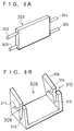
- Fig. 2 is also a schematic drawing showing a basic structure of a printer according to the present invention.
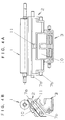
- Fig. 3 is a plan view and a right elevational view showing a specific structure of a printer according to the present invention.
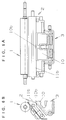
- Fig. 4 is a plan view and an elevational view showing the main portion of the printer shown in Fig. 3.
- Fig. 5 is a plan view and an elevational view showing an example of variation of the structure shown in Fig. 4.
- Fig. 6 is also a plan view and an elevational view showing another example of variation of the structure shown in Fig. 4.
- Fig. 7 is a schematic drawing showing an example of a conventional printer.
- Fig. 8 is a schematic drawing showing another example of a conventional printer.
- Fig. 9 is a schematic drawing showing still another example of a conventional printer.
- FIG. 1 shows basic structures of a printer according to the present invention, and three different aspects are denoted as (A), (B), and (C).
- a printer shown in Fig. 1(A) includes a frame (not shown), a platen 1, a printhead 2, and a pressing body 3 as a basic structure.
- the frame has left and right side walls which are disposed each other at a distance depending on the width of a recording medium (not shown).
- the platen 1 is rotatably provided to bridge between the two side walls.
- the platen 1 comprises a cylindrical elastic body 4 made of rubber or the like and a rotating shaft 5 which pierces the center of the elastic body 4.
- Both ends of the rotating shaft 5 are supported by the left and right side walls of the frame.
- the printhead 2 is also provided to bridge between the two side walls of the frame, and is disposed at the back of the platen 1.
- the printhead 2 comprises a head-supporting body 6 on which a thermal element (not shown) is mounted and a pair of pins 7 located at both ends of the head-supporting body 6.
- the head-supporting body 6 and the pins 7 can be integrally formed using material such as aluminum.
- the pressing body 3 is incorporated in the frame to make by pressing the printhead 2 at the back in contact with the platen 1 in front.
- the pressing body 3 has a horizontal shaft 8, a torsion spring 9 wound on the horizontal shaft 8, and a plane member 10 attached in the middle of the horizontal shaft 8.
- the torsion spring 9 generates pressing force to press forward the printhead 2 via the plane member 10.
- the thermal element, etc. provided on the printhead 2 are made in contact with the platen 1.
- the printhead 2 is flexibly engaged with the two side walls of the frame via the pins 7 at its both ends, and can tilt and move backward and forward and right and left according to the position of the platen 1.
- the pressing body 3 is in point contact with the printhead 2.
- the printhead 2 can be made by pressing uniformly in contact with the cylindrical body 4 following up the rotation of the platen 1.
- the printhead 2 and the pressing body 3 are formed of separate components which can be separately incorporated.
- the pressing body 3 has a plane member 10, at the back of the head-supporting body 6, a convex spherical surface portion 11 is formed.
- the structure is such that the plane member 10 and the convex spherical surface portion 11 are in point contact with each other.
- the printer shown in Fig. 1(B) has basically the same structure. Like reference numerals designate corresponding parts to those in the printer shown in Fig. 1(A) so as to be understood easily.
- the head-supporting body 6 has in the middle of its back a vertical convex cylindrical surface portion 11a.
- the pressing body 3 comprises a torsion spring 9 shown by a thick line.
- the middle portion 10a of the torsion spring 9 extends in the horizontal direction and has a convex cylindrical surface portion.
- the vertical convex cylindrical surface portion 11a formed on the side of the head-supporting body 6 and the convex cylindrical surface portion formed on the horizontal middle portion 10a on the side of the pressing body 3 intersect each other to be kept in point contact with each other.
- the printer shown in Fig. 1(C) also has basically the same structure. Like reference numerals designate corresponding parts to those in the printer shown in Fig. 1(A) so as to be understood easily.
- a convex cylindrical surface portion 11b which extends in the horizontal direction is formed.
- the pressing body 3 has a vertical post 10b substantially in the middle of the horizontal shaft 8. The vertical convex cylindrical surface of the post 10b and the horizontal cylindrical surface portion 11b on the side of the head-supporting body 6 intersect each other to form point contact between the bodies.
- Fig. 2 shows another example of a structure of a printer according to the present invention.
- (A) represents the printhead 2 and (B) represents a frame 12.
- the printhead 2 has the head-supporting body 6.
- a pair of upper and lower pins 7a and 7b are formed at the right end of the head-supporting body 6.
- a pair of upper and lower pins 7a and 7b are also formed at the left end of the head-supporting body 6.
- the head-supporting body 6 and the pins 7a and 7b can be integrally formed using material such as aluminum.
- the head-supporting body 6 has a wide upper portion 6a which is made by pressing in contact with the platen (not shown) and a narrow lower portion 6b. Therefore, the head-supporting body 6 according to the present embodiment is substantially T-shaped in the plan view.
- the frame 12 has left and right side walls 13 and 14 which are provided each other at a distance depending on the width of a recording medium (not shown).
- the right side wall 14 has a thin portion 12a to be engaged with the wide upper portion 6a of the head-supporting body 6 and a thick portion 12b to be engaged with the narrow lower portion 6b of the head-supporting body 6.
- a substantially arc-like guide slit 14a is formed in the thin portion 12a while a vertical guide slit 14b is formed in the thick portion 12b.
- the left side wall 13 is divided into the thin portion 12a and the thick portion 12b.
- the thin portion 12a has a substantially arc-like guide slit 13a while the thick portion 12b has a vertical guide slit.
- the distance between the two thin portions 12a which face each other across the width direction is set so as to exactly fit the width of the wide upper portion 6a of the head-supporting body 6.
- the distance between the two thick portions 12b which face each other across the width is set so as to fit the width of the narrow lower portion 6b of the head-supporting body 6.
- the printhead 2 is incorporated in the frame 12 dropwise from the above. By this, the printhead 2 is provided to bridge between the left and right side walls 13 and 14 of the frame 12. Looking at the right side wall 14, the upper pin 7a of the printhead 2 is engaged with the ark-like guide slit 14a while the lower pin 7b is engaged with the vertical guide slit 14b. With respect to the left side wall 13, the same thing can be said. With such a structure, the printhead 2, while bridging across the frame 12, rotates backward and forward with the lower pin 7b being the center of the rotation. It should be noted that a predetermined clearance is left between the pin 7b and the vertical guide slit 14b so that the printhead 2 can move backward and forward a little.
- the upper pin 7a moves along the ark-like guide slit 14a. Even when the printhead 2 rotates forward and touches the platen (not shown), the pin 7a does not touch the deepest portion of the guide slit 14a so that the printhead 2 can tilt right and left.
- the guide slit 14a precisely aligns the printhead 2 with respect to the vertical direction. With such a structure, the printhead 2 can tilt and move backward and forward and right and left according to the position of the platen.
- the pressing body (not shown) is in point contact with the printhead 2.
- the printhead 2 can be made by pressing uniformly in contact with the cylindrical surface of the platen following up the rotation of the platen.
- the dimension error and the installation error of the platen can be absorbed, and the deviation and the like can be effectively prevented.
- Fig. 3 is a plan view and a right elevational view showing an example of a specific structure of a printer according to the present invention.
- This printer is basically embodied by the combination of the structure of the pressing body shown in Fig. 1(A) and the structures of the printhead and the frame shown in Fig. 2. Therefore, like reference numerals designate corresponding parts so as to be understood easily.
- this printer is fabricated using the frame 12.
- the frame 12 has left and right side walls 13 and 14 which are at a distance depending on the width of a recording medium.
- the platen 1 is rotatably provided to bridge between the two side walls 13 and 14. As described in the above, the platen 1 has the cylindrical elastic body 4 made of rubber or the like and a rotating shaft 5.
- the rotating shaft 5 is supported by the left and right side walls 13 and 14, and is driven to rotate via a motor and a series of gears (not shown). By this, a recording medium is fed.
- the printhead 2 is also provided to bridge between the two side walls 13 and 14, and is disposed at the back of the platen 1. As described in the above, the printhead 2 has the head-supporting body 6 to the front face of which a board 15 is attached. On the board 15, a thermal element and a driving circuit are mounted. Further, a pressing member 16 of a flexible connector to be connected with the board 15 is also attached to the front face of the head-supporting body 6. On the other hand, the convex spherical surface portion is formed at the back of the head-supporting body 6.
- the head-supporting body 6 is divided into the wide upper portion 6a and the narrow lower portion 6b.
- the pin 7a formed in the wide upper portion 6a is engaged with the ark-like guide slit 14a formed in the thin portion 12a of the side wall 14.
- the pin 7b formed in the narrow lower portion 6b of the head-supporting body 6 is engaged with the vertical guide slit formed in the thick portion 12b of the side wall 14.
- the pressing body 3 has the horizontal shaft 8, by which the pressing body 3 is incorporated in the frame 12.
- the torsion spring 9 which generates predetermined pressing force is wound on the horizontal shaft 8.
- the plane member 10 is attached to the horizontal shaft 8.
- the plane member 10 is in point contact with the convex spherical surface portion 11 of the head-supporting body 6 described in the above. By this, the pressing body 3 makes the printhead 2 at the back in contact with the platen 1 in front.
- the right elevational view shows the state of the contact by pressing.
- the thermal element mounted on the front face of the head-supporting body 6 is in close contact with the cylindrical elastic body 4 of the platen 1 and performs predetermined print operation to a recording medium in between.
- the upper pin 7a of the printhead 2 can move in the arc-like guide slit 14a, and thus, the printhead 2 can tilt right and left to absorb deviation with the platen 1.
- the lower pin 7b of the head-supporting body 6 is engaged with the side wall 14 with a little clearance being left, and thus the head-supporting body 6 can tilt and move backward and forward.
- fine control of the tilted position of the printhead 2 with respect to the platen 1 is possible.
- the positioning of the printhead 2 is regulated by the upper pin 7a only in the vertical direction, and the incorporation is such that the printhead 2 can move right and left and backward and forward with respect to the frame 12.
- Fig. 4 shows only the main portion of the printer shown in Fig. 3 to clarify the relation of the arrangement.
- the pressing body 3 makes by pressing the printhead 2 in contact with the platen 1.
- the printhead 2 is attached to the frame by a pair of upper and lower pins 7a and 7b so as to move backward and forward and right and left.
- the convex spherical surface portion 11 of the printhead 2 is in point contact with the plane portion 10 of the pressing body 3.
- the printhead 2 is made by pressing in contact with the platen 1 following up the platen 1 backward and forward and right and left.
- Fig. 5 shows an example of variation of the structure shown in Fig. 4.
- Like reference numerals designate corresponding parts so as to be understood easily. It should be noted that this example of variation corresponds to the structure shown in Fig. 1(B).
- the convex cylindrical surface portion 11a which extends in the vertical direction is formed at the back of the printhead 2.
- the middle portion 10a of the torsion spring 9 incorporated in the pressing body 3 extends in the horizontal direction.
- the cylindrical surface portion of the middle portion 10a is orthogonal to and is in point contact with the cylindrical surface portion 11a on the side of the printhead 2.
- Fig. 6 shows another example of variation of the structure shown in Fig. 4.
- Like reference numerals designate corresponding parts so as to be understood easily.
- the convex cylindrical surface portion 11b in the horizontal direction is formed at the back of the printhead 2.
- the vertical convex cylindrical surface portion 10b is formed in the middle of the plane member 10 of the pressing body 3.
- the convex cylindrical surface portions 10b and 11b which are orthogonal to each other are in point contact with each other to enable the printhead 2 to tilt and move backward and forward and right and left.
- a printhead can tilt and move backward and forward and right and left, and can be made by pressing uniformly in contact with a platen. Therefore, it is effective for improving the print quality and the linearity of advance of a recording medium. Further, since a pressing body and a printhead are independent of each other, a printhead can be removed (exchanged) with ease. Still further, by making a printhead to be T-shaped, the dead space in a frame is effectively utilized, and at the same time, fabrication by dropping a printhead from the above is made possible. Together with this, a thin portion and a thick portion are provided in a side wall of a frame so as to improve the strength of the frame.
Abstract


Description
- The present invention relates to a printer with a platen and a printhead. More particularly, the present invention relates to a structure of supporting a printhead.
- Fig. 7 shows an example of a conventional printer. The printer includes a
platen 101 which is rotatably provided to bridge along the width direction of a recording medium (not shown). The printer also has aprinthead 102 which is disposed at the back of theplaten 101. Further, the printer includes apressing body 103 to make by pressing theprinthead 102 at the back in contact with theplaten 101 in front. Thepressing body 103 has avertical shaft 104 and ahorizontal shaft 105. Atorsion spring 106 is wound on thehorizontal shaft 105 to generate pressing force. Thevertical shaft 104 pierces theprinthead 102 to rotatably support theprinthead 102. - Fig. 8 shows another example of a conventional printer. (A) represents a
printhead 201 and (B) represents aframe 202. As shown in the figure, theframe 202 has left andright side walls printhead 201 is incorporated between the left andright side walls protrusions printhead 201, respectively. Throughholes protrusions right side walls holes printhead 201 is incorporated in theframe 202, the above-mentioned throughholes printhead 201 can be provided to bridge rotatably with respect to theframe 202. - Fig. 9 shows still another example of a conventional printer. A pair of upper and
lower pins printhead 301. In the same manner, a pair of upper andlower pins printhead 301. On the other hand, theframe 306 has left andright side walls 307 and 308 which are disposed each other at a distance depending on the width of a recording medium (not shown). Aguide slit 309 is formed in the left side wall 307. The guide slit 309 branches on the way into avertical branch portion 310 and an arc-like branch portion 311. In the same manner, aguide slit 312 is formed in theright side wall 308. The guide slit 312 branches into avertical branch portion 313 and an arc-like branch portion 314. The above-mentionedprinthead 301 is incorporated in theframe 306 dropwise from the above. In a fabricated state, theupper pin 302 is engaged with the arc-like branch portion 311 while thelower pin 303 is engaged with thevertical branch portion 310. In the same manner, theupper pin 304 is engaged with the arc-like branch portion 314 while thelower pin 305 is engaged with thevertical branch portion 313. In this state, theprinthead 301 rotates backward and forward with thelower pins upper pins like branch portions - In the conventional printer shown in Fig. 7, the
printhead 102 is axially supported by thevertical shaft 104 of thepressing body 103 so that theprinthead 102 can tilt right and left. Therefore, when theprinthead 102 at the back is made in contact with theplaten 101 in front by the action of thetorsion spring 106, theprinthead 102 can tilt and move right and left to absorb the deviation. However, since thehorizontal shaft 105 connected with thevertical shaft 104 is supported with respect to the frame, theprinthead 102 is made by pressing in contact with theplaten 101 in a fixed tilted position with respect to the direction of backward and forward. Since the extent of the tilt of theprinthead 102 in the directions backward and forward can not be adjusted, it is difficult to completely absorb the dimensional error and the installation error of theplaten 101. - In the conventional printer shown in Fig. 8, the through
holes printhead 201 is incorporated in theframe 202. The positioning is time-consuming and therefore, the fabricativity is inferior. In addition, since theprinthead 201 and theframe 202 are coupled each other by a horizontal shaft (not shown), theprinthead 201 rotates only backward and forward. As theprinthead 201 can not tilt and move right and left, the deviation with the platen (not shown) can not be absorbed. Still further, since the tilted position in the directions of backward and forward is regulated, the dimensional error and the installation error of the platen can not be absorbed. - In the conventional printer shown in Fig. 9, the
printhead 301 can be incorporated in theframe 306 dropwise from the above, and thus fabricativity is improved compared with the conventional printer shown in Fig. 8. However, this printer has a problem that, since the guide slits 309 and 312 having branches are formed in the left andright side walls 307 and 308, the strength of the frame is lowered. - An object of the present invention is to provide a printer having a structure with which a printhead is made by pressing uniformly in contact with a platen. Another object of the present invention is to provide a printer with excellent incorporativity of a printhead and excellent strength of a frame.
- A printer according to the present invention comprises a frame, a platen, a printhead, and a pressing body as a basic structure. The frame has left and right side walls which are provided each other at a distance depending on the width of a recording medium. The platen is rotatably provided to bridge between the two side walls. The printhead is also provided between the two side walls, and is disposed at the back of the platen. The pressing body is incorporated in the frame to make by pressing the printhead at the back in contact with the platen in front. As characteristic matters, the printhead can tilt and move backward and forward and right and left according to the position of the platen, and the pressing body is in point contact with the printhead. With such a structure, in print operation, the printhead can be made by pressing in contact with the platen following up the platen.
- Specifically, the printhead and the pressing body are formed of separate components which can be separately incorporated. One of the printhead and the pressing body has a convex spherical surface portion, and the other has a plane portion. The convex spherical surface portion and the plane portion are in point contact with each other. Alternatively, the printhead and the pressing body may have convex cylindrical surface portions which intersect each other to be made in point contact with each other. Preferably, the printhead has a wide upper portion which is made by pressing in contact with the platen and a narrow lower portion which is integral with the wide upper portion. On the other hand, the left and right side walls have thin portions to be engaged with the wide upper portion and thick portions to be engaged with the narrow lower portion, respectively.
- According to the present invention, a printhead can tilt and move backward and forward and right and left according to the position of a platen. Further, a pressing body is in point contact with a printhead. Since the operating portion of the press is a point, a printhead can tilt and move backward and forward and right and left, and can be made by pressing uniformly in contact with a platen. By this, deviation can be prevented, which is effective for improving the print quality (by preventing a blur) and the linearity of advance of a recording medium. Further, since a pressing body and a printhead are independent of each other, the printhead can be incorporated or exchanged with ease. Still further, a printhead is T-shaped having a wide upper portion and a narrow lower portion integral with the wide upper portion. According to this, the side walls of a frame are divided into thin portions and thick portions. With such a structure, the strength of the frame is improved. Further, a printhead can be incorporated in the frame dropwise from the above, and the dead space inside the frame can be effectively utilized. Different from the conventional printer, since there is no need to insert a horizontal shaft and the incorporation can be done from above, the fabricativity is improved. Since through holes through which a horizontal shaft is inserted are not necessary, the structure of a die for forming a printhead can be simplified (sliding is unnecessary) to lower the cost.
- Fig. 1 are schematic drawings showing basic structures of a printer according to the present invention. Fig. 2 is also a schematic drawing showing a basic structure of a printer according to the present invention. Fig. 3 is a plan view and a right elevational view showing a specific structure of a printer according to the present invention. Fig. 4 is a plan view and an elevational view showing the main portion of the printer shown in Fig. 3. Fig. 5 is a plan view and an elevational view showing an example of variation of the structure shown in Fig. 4. Fig. 6 is also a plan view and an elevational view showing another example of variation of the structure shown in Fig. 4. Fig. 7 is a schematic drawing showing an example of a conventional printer. Fig. 8 is a schematic drawing showing another example of a conventional printer. Fig. 9 is a schematic drawing showing still another example of a conventional printer.
- Preferred embodiments of the present invention will now be described in detail in the following with reference to the drawings. Fig. 1 shows basic structures of a printer according to the present invention, and three different aspects are denoted as (A), (B), and (C). A printer shown in Fig. 1(A) includes a frame (not shown), a
platen 1, aprinthead 2, and apressing body 3 as a basic structure. The frame has left and right side walls which are disposed each other at a distance depending on the width of a recording medium (not shown). Theplaten 1 is rotatably provided to bridge between the two side walls. Specifically, theplaten 1 comprises a cylindricalelastic body 4 made of rubber or the like and arotating shaft 5 which pierces the center of theelastic body 4. Both ends of therotating shaft 5 are supported by the left and right side walls of the frame. Theprinthead 2 is also provided to bridge between the two side walls of the frame, and is disposed at the back of theplaten 1. Specifically, theprinthead 2 comprises a head-supportingbody 6 on which a thermal element (not shown) is mounted and a pair ofpins 7 located at both ends of the head-supportingbody 6. The head-supportingbody 6 and thepins 7 can be integrally formed using material such as aluminum. Thepressing body 3 is incorporated in the frame to make by pressing theprinthead 2 at the back in contact with theplaten 1 in front. Specifically, thepressing body 3 has ahorizontal shaft 8, atorsion spring 9 wound on thehorizontal shaft 8, and aplane member 10 attached in the middle of thehorizontal shaft 8. Thetorsion spring 9 generates pressing force to press forward theprinthead 2 via theplane member 10. By this, the thermal element, etc. provided on theprinthead 2 are made in contact with theplaten 1. - As characteristic matters of the present invention, the
printhead 2 is flexibly engaged with the two side walls of the frame via thepins 7 at its both ends, and can tilt and move backward and forward and right and left according to the position of theplaten 1. On the other hand, thepressing body 3 is in point contact with theprinthead 2. With such a structure, during printing operation, theprinthead 2 can be made by pressing uniformly in contact with thecylindrical body 4 following up the rotation of theplaten 1. It should be noted that theprinthead 2 and thepressing body 3 are formed of separate components which can be separately incorporated. In the present embodiment, while thepressing body 3 has aplane member 10, at the back of the head-supportingbody 6, a convexspherical surface portion 11 is formed. The structure is such that theplane member 10 and the convexspherical surface portion 11 are in point contact with each other. - The printer shown in Fig. 1(B) has basically the same structure. Like reference numerals designate corresponding parts to those in the printer shown in Fig. 1(A) so as to be understood easily. In the present embodiment, the head-supporting
body 6 has in the middle of its back a vertical convexcylindrical surface portion 11a. On the other hand, thepressing body 3 comprises atorsion spring 9 shown by a thick line. Themiddle portion 10a of thetorsion spring 9 extends in the horizontal direction and has a convex cylindrical surface portion. The vertical convexcylindrical surface portion 11a formed on the side of the head-supportingbody 6 and the convex cylindrical surface portion formed on the horizontalmiddle portion 10a on the side of thepressing body 3 intersect each other to be kept in point contact with each other. - The printer shown in Fig. 1(C) also has basically the same structure. Like reference numerals designate corresponding parts to those in the printer shown in Fig. 1(A) so as to be understood easily. At the back of the head-supporting
body 6, a convexcylindrical surface portion 11b which extends in the horizontal direction is formed. On the other hand, thepressing body 3 has avertical post 10b substantially in the middle of thehorizontal shaft 8. The vertical convex cylindrical surface of thepost 10b and the horizontalcylindrical surface portion 11b on the side of the head-supportingbody 6 intersect each other to form point contact between the bodies. - Fig. 2 shows another example of a structure of a printer according to the present invention. (A) represents the
printhead 2 and (B) represents aframe 12. Theprinthead 2 has the head-supportingbody 6. A pair of upper andlower pins body 6. In the same manner, a pair of upper andlower pins body 6. The head-supportingbody 6 and thepins body 6 can be simplified (sliding is unnecessary) to lower the cost. As shown in the figure, the head-supportingbody 6 has a wideupper portion 6a which is made by pressing in contact with the platen (not shown) and a narrowlower portion 6b. Therefore, the head-supportingbody 6 according to the present embodiment is substantially T-shaped in the plan view. - On the other hand, the
frame 12 has left andright side walls right side wall 14 has athin portion 12a to be engaged with the wideupper portion 6a of the head-supportingbody 6 and athick portion 12b to be engaged with the narrowlower portion 6b of the head-supportingbody 6. A substantially arc-like guide slit 14a is formed in thethin portion 12a while avertical guide slit 14b is formed in thethick portion 12b. In the same manner, theleft side wall 13 is divided into thethin portion 12a and thethick portion 12b. Thethin portion 12a has a substantially arc-like guide slit 13a while thethick portion 12b has a vertical guide slit. - The distance between the two
thin portions 12a which face each other across the width direction is set so as to exactly fit the width of the wideupper portion 6a of the head-supportingbody 6. In the same manner, the distance between the twothick portions 12b which face each other across the width is set so as to fit the width of the narrowlower portion 6b of the head-supportingbody 6. Thus, it is possible to provide a step between thethin portion 12a and thethick portion 12b on the side of theframe 12 according to the difference in size of the wideupper portion 6a and the narrowlower portion 6b on the side of the head-supportingbody 6. With such a structure, the mechanical strength of the pair of left andright side walls thick portion 12b is provided utilizing the dead space inside theframe 12, the width of the frame does not increase compared to a conventional one. Theframe 12 having such a structure can be formed by injection molding of resin or the like. - The
printhead 2 is incorporated in theframe 12 dropwise from the above. By this, theprinthead 2 is provided to bridge between the left andright side walls frame 12. Looking at theright side wall 14, theupper pin 7a of theprinthead 2 is engaged with the ark-like guide slit 14a while thelower pin 7b is engaged with thevertical guide slit 14b. With respect to theleft side wall 13, the same thing can be said. With such a structure, theprinthead 2, while bridging across theframe 12, rotates backward and forward with thelower pin 7b being the center of the rotation. It should be noted that a predetermined clearance is left between thepin 7b and the vertical guide slit 14b so that theprinthead 2 can move backward and forward a little. When theprinthead 2 rotates backward and forward, theupper pin 7a moves along the ark-like guide slit 14a. Even when theprinthead 2 rotates forward and touches the platen (not shown), thepin 7a does not touch the deepest portion of the guide slit 14a so that theprinthead 2 can tilt right and left. It should be noted that the guide slit 14a precisely aligns theprinthead 2 with respect to the vertical direction. With such a structure, theprinthead 2 can tilt and move backward and forward and right and left according to the position of the platen. On the other hand, as described in the above, the pressing body (not shown) is in point contact with theprinthead 2. Thus, during printing operation, theprinthead 2 can be made by pressing uniformly in contact with the cylindrical surface of the platen following up the rotation of the platen. In other words, the dimension error and the installation error of the platen can be absorbed, and the deviation and the like can be effectively prevented. - Fig. 3 is a plan view and a right elevational view showing an example of a specific structure of a printer according to the present invention. This printer is basically embodied by the combination of the structure of the pressing body shown in Fig. 1(A) and the structures of the printhead and the frame shown in Fig. 2. Therefore, like reference numerals designate corresponding parts so as to be understood easily. As shown in the figure, this printer is fabricated using the
frame 12. Theframe 12 has left andright side walls platen 1 is rotatably provided to bridge between the twoside walls platen 1 has the cylindricalelastic body 4 made of rubber or the like and arotating shaft 5. Therotating shaft 5 is supported by the left andright side walls printhead 2 is also provided to bridge between the twoside walls platen 1. As described in the above, theprinthead 2 has the head-supportingbody 6 to the front face of which aboard 15 is attached. On theboard 15, a thermal element and a driving circuit are mounted. Further, a pressingmember 16 of a flexible connector to be connected with theboard 15 is also attached to the front face of the head-supportingbody 6. On the other hand, the convex spherical surface portion is formed at the back of the head-supportingbody 6. As described in the above, the head-supportingbody 6 is divided into the wideupper portion 6a and the narrowlower portion 6b. Thepin 7a formed in the wideupper portion 6a is engaged with the ark-like guide slit 14a formed in thethin portion 12a of theside wall 14. Thepin 7b formed in the narrowlower portion 6b of the head-supportingbody 6 is engaged with the vertical guide slit formed in thethick portion 12b of theside wall 14. - The
pressing body 3 has thehorizontal shaft 8, by which thepressing body 3 is incorporated in theframe 12. Thetorsion spring 9 which generates predetermined pressing force is wound on thehorizontal shaft 8. Theplane member 10 is attached to thehorizontal shaft 8. Theplane member 10 is in point contact with the convexspherical surface portion 11 of the head-supportingbody 6 described in the above. By this, thepressing body 3 makes theprinthead 2 at the back in contact with theplaten 1 in front. The right elevational view shows the state of the contact by pressing. The thermal element mounted on the front face of the head-supportingbody 6 is in close contact with the cylindricalelastic body 4 of theplaten 1 and performs predetermined print operation to a recording medium in between. Here, theupper pin 7a of theprinthead 2 can move in the arc-like guide slit 14a, and thus, theprinthead 2 can tilt right and left to absorb deviation with theplaten 1. Further, thelower pin 7b of the head-supportingbody 6 is engaged with theside wall 14 with a little clearance being left, and thus the head-supportingbody 6 can tilt and move backward and forward. In other words, fine control of the tilted position of theprinthead 2 with respect to theplaten 1 is possible. In other words, the positioning of theprinthead 2 is regulated by theupper pin 7a only in the vertical direction, and the incorporation is such that theprinthead 2 can move right and left and backward and forward with respect to theframe 12. - Fig. 4 shows only the main portion of the printer shown in Fig. 3 to clarify the relation of the arrangement. As shown in the figure, the
pressing body 3 makes by pressing theprinthead 2 in contact with theplaten 1. Theprinthead 2 is attached to the frame by a pair of upper andlower pins spherical surface portion 11 of theprinthead 2 is in point contact with theplane portion 10 of thepressing body 3. With such a structure, theprinthead 2 is made by pressing in contact with theplaten 1 following up theplaten 1 backward and forward and right and left. - Fig. 5 shows an example of variation of the structure shown in Fig. 4. Like reference numerals designate corresponding parts so as to be understood easily. It should be noted that this example of variation corresponds to the structure shown in Fig. 1(B). The convex
cylindrical surface portion 11a which extends in the vertical direction is formed at the back of theprinthead 2. On the other hand, themiddle portion 10a of thetorsion spring 9 incorporated in thepressing body 3 extends in the horizontal direction. The cylindrical surface portion of themiddle portion 10a is orthogonal to and is in point contact with thecylindrical surface portion 11a on the side of theprinthead 2. - Fig. 6 shows another example of variation of the structure shown in Fig. 4. Like reference numerals designate corresponding parts so as to be understood easily. In the present example, the convex
cylindrical surface portion 11b in the horizontal direction is formed at the back of theprinthead 2. On the other hand, the vertical convexcylindrical surface portion 10b is formed in the middle of theplane member 10 of thepressing body 3. The convexcylindrical surface portions printhead 2 to tilt and move backward and forward and right and left. - According to the present invention, since the operating portion of the press is a point, a printhead can tilt and move backward and forward and right and left, and can be made by pressing uniformly in contact with a platen. Therefore, it is effective for improving the print quality and the linearity of advance of a recording medium. Further, Since a pressing body and a printhead are independent of each other, a printhead can be removed (exchanged) with ease. Still further, by making a printhead to be T-shaped, the dead space in a frame is effectively utilized, and at the same time, fabrication by dropping a printhead from the above is made possible. Together with this, a thin portion and a thick portion are provided in a side wall of a frame so as to improve the strength of the frame.
Claims (6)
- A printer comprising a frame having left and right side walls which are provided each other at a distance depending on the width of a recording medium, a platen rotatably provided to bridge between said side walls, a printhead also provided to bridge between said side walls and disposed at the back of said platen, and a pressing body which is incorporated in said frame and which makes by pressing said printhead at the back in contact with said platen in front, characterized in that said printhead can tilt and move backward and forward and right and left according to the position of said platen, and said pressing body is in point contact with said printhead, whereby, in print operation, said printhead is made in contact with said platen following up said platen.
- The printer according to claim 1, characterized in that said printhead and said pressing body are formed of separate components which can be separately incorporated.
- The printer according to claim 1, characterized in that one of said printhead and said pressing body has a convex spherical surface portion, the other has a plane portion, and said convex spherical surface portion and said plane portion are in point contact with each other.
- The printer according to claim 1, characterized in that said printhead and said pressing body have convex cylindrical surface portions which intersect each other, and said convex cylindrical surface portions are made in point contact with each other.
- The printer according to claim 1, characterized in that said printhead has a wide upper portion which is made by pressing in contact with said platen and a narrow lower portion which is integral with said wide upper portion, and said left and right side walls have thin portions to be engaged with said wide upper portion and thick portions to be engaged with said narrow lower portion, respectively.
- The printer comprising a frame having left and right side walls which are provided each other at a distance depending on the width of a recording medium, a platen rotatably provided to bridge between said side walls, a printhead rotatably supported between said side walls and disposed at the back of said platen, and a pressing body which makes by pressing said printhead at the back in contact with said platen in front, characterized in that said printhead has a wide upper portion which is made by pressing in contact with said platen and a narrow lower portion which is integral with said wide upper portion, and said left and right side walls have thin portions supporting said wide upper portion and thick portions supporting said narrow lower portion, respectively.
Priority Applications (1)
| Application Number | Priority Date | Filing Date | Title |
|---|---|---|---|
| EP98202842A EP0885736B1 (en) | 1994-11-08 | 1995-11-08 | Printer |
Applications Claiming Priority (4)
| Application Number | Priority Date | Filing Date | Title |
|---|---|---|---|
| JP6273259A JP2770141B2 (en) | 1994-11-08 | 1994-11-08 | Printer |
| JP27325994 | 1994-11-08 | ||
| JP273259/94 | 1994-11-08 | ||
| PCT/JP1995/002277 WO1996014213A1 (en) | 1994-11-08 | 1995-11-08 | Printer |
Related Child Applications (1)
| Application Number | Title | Priority Date | Filing Date |
|---|---|---|---|
| EP98202842A Division EP0885736B1 (en) | 1994-11-08 | 1995-11-08 | Printer |
Publications (3)
| Publication Number | Publication Date |
|---|---|
| EP0738606A1 true EP0738606A1 (en) | 1996-10-23 |
| EP0738606A4 EP0738606A4 (en) | 1997-02-19 |
| EP0738606B1 EP0738606B1 (en) | 2000-03-15 |
Family
ID=17525341
Family Applications (2)
| Application Number | Title | Priority Date | Filing Date |
|---|---|---|---|
| EP98202842A Expired - Lifetime EP0885736B1 (en) | 1994-11-08 | 1995-11-08 | Printer |
| EP95936749A Expired - Lifetime EP0738606B1 (en) | 1994-11-08 | 1995-11-08 | Printer |
Family Applications Before (1)
| Application Number | Title | Priority Date | Filing Date |
|---|---|---|---|
| EP98202842A Expired - Lifetime EP0885736B1 (en) | 1994-11-08 | 1995-11-08 | Printer |
Country Status (6)
| Country | Link |
|---|---|
| US (1) | US5746520A (en) |
| EP (2) | EP0885736B1 (en) |
| JP (1) | JP2770141B2 (en) |
| DE (2) | DE69515638T2 (en) |
| HK (1) | HK1016129A1 (en) |
| WO (1) | WO1996014213A1 (en) |
Cited By (3)
| Publication number | Priority date | Publication date | Assignee | Title |
|---|---|---|---|---|
| WO1998040642A1 (en) | 1997-03-11 | 1998-09-17 | A.P.S. Engineering S.A.R.L. | Maintaining and compressing spring and its application in a compact printing device |
| WO1998040221A1 (en) | 1997-03-11 | 1998-09-17 | A.P.S. Engineering S.A.R.L. | Compact printing mechanism |
| WO2004110770A1 (en) * | 2003-06-18 | 2004-12-23 | Espera-Werke Gmbh | Printing device |
Families Citing this family (18)
| Publication number | Priority date | Publication date | Assignee | Title |
|---|---|---|---|---|
| JP3864659B2 (en) * | 2000-01-26 | 2007-01-10 | セイコーエプソン株式会社 | Head pressing mechanism and printer having the same |
| US6588624B1 (en) | 2000-05-24 | 2003-07-08 | Lexmark International, Inc. | Cover damping mechanism |
| FR2837423B1 (en) * | 2002-03-21 | 2004-06-18 | A P S Engineering | THERMAL PRINTING MECHANISM, ESPECIALLY APPLICABLE TO PAYMENT TERMINALS |
| NL1025754C2 (en) * | 2004-03-18 | 2005-09-20 | Oce Tech Bv | Device for accurately positioning an object on a frame. |
| JP4000478B2 (en) * | 2004-04-28 | 2007-10-31 | 船井電機株式会社 | Sublimation printer |
| JP4306548B2 (en) * | 2004-07-05 | 2009-08-05 | 船井電機株式会社 | Image forming apparatus |
| JP4914619B2 (en) * | 2006-02-23 | 2012-04-11 | セイコーインスツル株式会社 | Head support structure, printing apparatus, thermal activation apparatus, and printer |
| JP4715609B2 (en) * | 2006-04-17 | 2011-07-06 | 船井電機株式会社 | Image forming apparatus |
| JP2007331112A (en) * | 2006-06-12 | 2007-12-27 | Seiko Epson Corp | Thermal printer |
| JP4588673B2 (en) * | 2006-07-28 | 2010-12-01 | アルプス電気株式会社 | Printer |
| JP5058708B2 (en) * | 2006-10-20 | 2012-10-24 | 東芝テック株式会社 | Thermal printer unit |
| JP5153946B2 (en) * | 2006-10-20 | 2013-02-27 | 東芝テック株式会社 | Thermal printer unit |
| JP4285545B2 (en) * | 2007-01-10 | 2009-06-24 | 船井電機株式会社 | Image forming apparatus |
| CN102056746B (en) * | 2008-06-13 | 2012-10-17 | 勃来迪环球股份有限公司 | Print head with uniform loading |
| JP5270321B2 (en) * | 2008-12-05 | 2013-08-21 | 富士通コンポーネント株式会社 | Printer module |
| JP6225567B2 (en) * | 2013-08-30 | 2017-11-08 | セイコーエプソン株式会社 | Print head and printing apparatus |
| US9604475B2 (en) | 2015-05-08 | 2017-03-28 | Zih Corp. | Media processing device with enhanced media and ribbon loading and unloading features |
| KR102047524B1 (en) * | 2017-11-29 | 2019-11-21 | 디에스글로벌(주) | Photo printer |
Citations (5)
| Publication number | Priority date | Publication date | Assignee | Title |
|---|---|---|---|---|
| EP0267580A2 (en) * | 1986-11-10 | 1988-05-18 | Kanzaki Paper Manufacturing Company Limited | Thermal printer with a mechanism for preventing a recording sheet's meandering |
| DE3928590A1 (en) * | 1988-09-05 | 1990-03-15 | Alps Electric Co Ltd | Thermal printer damping element - is inserted between frame and support for bearing surface at rear of recording sheet |
| US4949098A (en) * | 1987-12-28 | 1990-08-14 | Pitney Bowes Inc. | Thermal printhead controlling means |
| EP0463595A2 (en) * | 1990-06-26 | 1992-01-02 | Seiko Epson Corporation | Line thermal printer |
| US5304007A (en) * | 1991-05-05 | 1994-04-19 | Gulton Industries, Inc. | Thermal printhead balanced spring mount |
Family Cites Families (12)
| Publication number | Priority date | Publication date | Assignee | Title |
|---|---|---|---|---|
| IT1118078B (en) * | 1977-05-04 | 1986-02-24 | Olivetti & Co Spa | IMPACT IMPROVEMENTS ON A PRINTER |
| US4169682A (en) * | 1978-01-31 | 1979-10-02 | Texas Instruments Incorporated | Printer mechanism |
| JPS59143755A (en) * | 1983-02-07 | 1984-08-17 | 株式会社ダイフク | Monorail type self-advancing truck |
| EP0213934B1 (en) * | 1985-08-29 | 1992-01-02 | Seiko Epson Corporation | Print head positioning apparatus |
| DE3879346T2 (en) * | 1987-09-29 | 1993-09-30 | Sharp Kk | Actuation mechanism for the print head of a recording device. |
| JPH01226376A (en) * | 1988-03-08 | 1989-09-11 | Seiko Epson Corp | Support mechanism of thermal printing head |
| JPH01178950U (en) * | 1988-06-03 | 1989-12-21 | ||
| JPH02185448A (en) * | 1989-01-13 | 1990-07-19 | Canon Inc | Image recording device |
| JPH0381172A (en) * | 1989-08-24 | 1991-04-05 | Fujitsu Ltd | Thermal printer |
| JP2562709B2 (en) * | 1990-03-27 | 1996-12-11 | 株式会社田村電機製作所 | Print head holding structure |
| US5156467A (en) * | 1990-07-13 | 1992-10-20 | Tokyo Electric Co., Ltd. | Printer with media thickness adjustment of platen |
| JP3089829B2 (en) * | 1992-05-28 | 2000-09-18 | 松下電器産業株式会社 | Thermal line printer |
-
1994
- 1994-11-08 JP JP6273259A patent/JP2770141B2/en not_active Expired - Fee Related
-
1995
- 1995-11-08 EP EP98202842A patent/EP0885736B1/en not_active Expired - Lifetime
- 1995-11-08 DE DE69515638T patent/DE69515638T2/en not_active Expired - Fee Related
- 1995-11-08 DE DE69529925T patent/DE69529925T2/en not_active Expired - Lifetime
- 1995-11-08 EP EP95936749A patent/EP0738606B1/en not_active Expired - Lifetime
- 1995-11-08 WO PCT/JP1995/002277 patent/WO1996014213A1/en active IP Right Grant
- 1995-11-08 US US08/676,134 patent/US5746520A/en not_active Expired - Lifetime
-
1999
- 1999-03-24 HK HK99101244A patent/HK1016129A1/en not_active IP Right Cessation
Patent Citations (5)
| Publication number | Priority date | Publication date | Assignee | Title |
|---|---|---|---|---|
| EP0267580A2 (en) * | 1986-11-10 | 1988-05-18 | Kanzaki Paper Manufacturing Company Limited | Thermal printer with a mechanism for preventing a recording sheet's meandering |
| US4949098A (en) * | 1987-12-28 | 1990-08-14 | Pitney Bowes Inc. | Thermal printhead controlling means |
| DE3928590A1 (en) * | 1988-09-05 | 1990-03-15 | Alps Electric Co Ltd | Thermal printer damping element - is inserted between frame and support for bearing surface at rear of recording sheet |
| EP0463595A2 (en) * | 1990-06-26 | 1992-01-02 | Seiko Epson Corporation | Line thermal printer |
| US5304007A (en) * | 1991-05-05 | 1994-04-19 | Gulton Industries, Inc. | Thermal printhead balanced spring mount |
Non-Patent Citations (1)
| Title |
|---|
| See also references of WO9614213A1 * |
Cited By (5)
| Publication number | Priority date | Publication date | Assignee | Title |
|---|---|---|---|---|
| WO1998040642A1 (en) | 1997-03-11 | 1998-09-17 | A.P.S. Engineering S.A.R.L. | Maintaining and compressing spring and its application in a compact printing device |
| WO1998040221A1 (en) | 1997-03-11 | 1998-09-17 | A.P.S. Engineering S.A.R.L. | Compact printing mechanism |
| WO2004110770A1 (en) * | 2003-06-18 | 2004-12-23 | Espera-Werke Gmbh | Printing device |
| US7256808B2 (en) | 2003-06-18 | 2007-08-14 | Espera-Werke Gmbh | Printing device |
| CN100423950C (en) * | 2003-06-18 | 2008-10-08 | 艾斯普拉工厂有限公司 | Printing device |
Also Published As
| Publication number | Publication date |
|---|---|
| DE69529925T2 (en) | 2003-10-09 |
| DE69515638D1 (en) | 2000-04-20 |
| WO1996014213A1 (en) | 1996-05-17 |
| EP0885736A3 (en) | 1999-03-17 |
| US5746520A (en) | 1998-05-05 |
| EP0738606B1 (en) | 2000-03-15 |
| DE69515638T2 (en) | 2000-11-09 |
| JPH08132706A (en) | 1996-05-28 |
| EP0738606A4 (en) | 1997-02-19 |
| JP2770141B2 (en) | 1998-06-25 |
| HK1016129A1 (en) | 1999-10-29 |
| EP0885736B1 (en) | 2003-03-12 |
| EP0885736A2 (en) | 1998-12-23 |
| DE69529925D1 (en) | 2003-04-17 |
Similar Documents
| Publication | Publication Date | Title |
|---|---|---|
| EP0738606A1 (en) | Printer | |
| JP3326780B2 (en) | Printer | |
| US4744686A (en) | Device for carrying printing head | |
| WO2005090086A1 (en) | Thermal printing mechanism | |
| JPS585786B2 (en) | Print head assembly position adjustment mechanism | |
| US4046245A (en) | Carriage stabilization means for a serial printer | |
| JP4415435B2 (en) | Ink carrier | |
| JPH03199069A (en) | Platen-supporting device in line thermal printer | |
| EP0529652B1 (en) | Impact dot printer | |
| JP2608476B2 (en) | Serial impact printer | |
| KR100533409B1 (en) | Print unit and a printer using the same | |
| JP3108786B2 (en) | Serial printer | |
| JP3340542B2 (en) | Image recording device | |
| JPH09229081A (en) | Shaft member supporting construction | |
| JPH0639981Y2 (en) | Serial thermal printer | |
| KR900005409B1 (en) | Thermal printer head | |
| JPH0585012A (en) | Head pressurizing device for thermal printer | |
| JPS6412237B2 (en) | ||
| KR20240002707A (en) | Printing unit and portable terminal | |
| JPH0739179A (en) | Oscillatory wave motor and printer using the same | |
| JPH0387280A (en) | Printer | |
| JPH05278239A (en) | Printing head position adjusting device | |
| JPH05116420A (en) | Head gap regulating device for printing device | |
| KR900004743Y1 (en) | Print gap adjustment device for typewriter | |
| JPS5818270A (en) | Assembly of print head |
Legal Events
| Date | Code | Title | Description |
|---|---|---|---|
| PUAI | Public reference made under article 153(3) epc to a published international application that has entered the european phase |
Free format text: ORIGINAL CODE: 0009012 |
|
| 17P | Request for examination filed |
Effective date: 19960712 |
|
| AK | Designated contracting states |
Kind code of ref document: A1 Designated state(s): DE FR GB IT |
|
| A4 | Supplementary search report drawn up and despatched | ||
| AK | Designated contracting states |
Kind code of ref document: A4 Designated state(s): DE FR GB IT |
|
| 17Q | First examination report despatched |
Effective date: 19980226 |
|
| GRAG | Despatch of communication of intention to grant |
Free format text: ORIGINAL CODE: EPIDOS AGRA |
|
| GRAG | Despatch of communication of intention to grant |
Free format text: ORIGINAL CODE: EPIDOS AGRA |
|
| GRAH | Despatch of communication of intention to grant a patent |
Free format text: ORIGINAL CODE: EPIDOS IGRA |
|
| GRAH | Despatch of communication of intention to grant a patent |
Free format text: ORIGINAL CODE: EPIDOS IGRA |
|
| GRAA | (expected) grant |
Free format text: ORIGINAL CODE: 0009210 |
|
| ITF | It: translation for a ep patent filed |
Owner name: JACOBACCI & PERANI S.P.A. |
|
| AK | Designated contracting states |
Kind code of ref document: B1 Designated state(s): DE FR GB IT |
|
| REF | Corresponds to: |
Ref document number: 69515638 Country of ref document: DE Date of ref document: 20000420 |
|
| ET | Fr: translation filed | ||
| PLBE | No opposition filed within time limit |
Free format text: ORIGINAL CODE: 0009261 |
|
| STAA | Information on the status of an ep patent application or granted ep patent |
Free format text: STATUS: NO OPPOSITION FILED WITHIN TIME LIMIT |
|
| 26N | No opposition filed | ||
| REG | Reference to a national code |
Ref country code: GB Ref legal event code: IF02 |
|
| PGFP | Annual fee paid to national office [announced via postgrant information from national office to epo] |
Ref country code: GB Payment date: 20041104 Year of fee payment: 10 Ref country code: DE Payment date: 20041104 Year of fee payment: 10 |
|
| PG25 | Lapsed in a contracting state [announced via postgrant information from national office to epo] |
Ref country code: GB Free format text: LAPSE BECAUSE OF NON-PAYMENT OF DUE FEES Effective date: 20051108 |
|
| PG25 | Lapsed in a contracting state [announced via postgrant information from national office to epo] |
Ref country code: DE Free format text: LAPSE BECAUSE OF NON-PAYMENT OF DUE FEES Effective date: 20060601 |
|
| GBPC | Gb: european patent ceased through non-payment of renewal fee |
Effective date: 20051108 |
|
| PGFP | Annual fee paid to national office [announced via postgrant information from national office to epo] |
Ref country code: FR Payment date: 20101123 Year of fee payment: 16 |
|
| PGFP | Annual fee paid to national office [announced via postgrant information from national office to epo] |
Ref country code: IT Payment date: 20101115 Year of fee payment: 16 |
|
| REG | Reference to a national code |
Ref country code: FR Ref legal event code: ST Effective date: 20120731 |
|
| PG25 | Lapsed in a contracting state [announced via postgrant information from national office to epo] |
Ref country code: IT Free format text: LAPSE BECAUSE OF NON-PAYMENT OF DUE FEES Effective date: 20111108 |
|
| PG25 | Lapsed in a contracting state [announced via postgrant information from national office to epo] |
Ref country code: FR Free format text: LAPSE BECAUSE OF NON-PAYMENT OF DUE FEES Effective date: 20111130 |