EP0738432B1 - Device for differentially protecting a power transformer - Google Patents
Device for differentially protecting a power transformer Download PDFInfo
- Publication number
- EP0738432B1 EP0738432B1 EP95905167A EP95905167A EP0738432B1 EP 0738432 B1 EP0738432 B1 EP 0738432B1 EP 95905167 A EP95905167 A EP 95905167A EP 95905167 A EP95905167 A EP 95905167A EP 0738432 B1 EP0738432 B1 EP 0738432B1
- Authority
- EP
- European Patent Office
- Prior art keywords
- current
- transformer
- neural network
- fault
- representative
- Prior art date
- Legal status (The legal status is an assumption and is not a legal conclusion. Google has not performed a legal analysis and makes no representation as to the accuracy of the status listed.)
- Expired - Lifetime
Links
Images


Classifications
-
- H—ELECTRICITY
- H02—GENERATION; CONVERSION OR DISTRIBUTION OF ELECTRIC POWER
- H02H—EMERGENCY PROTECTIVE CIRCUIT ARRANGEMENTS
- H02H7/00—Emergency protective circuit arrangements specially adapted for specific types of electric machines or apparatus or for sectionalised protection of cable or line systems, and effecting automatic switching in the event of an undesired change from normal working conditions
- H02H7/04—Emergency protective circuit arrangements specially adapted for specific types of electric machines or apparatus or for sectionalised protection of cable or line systems, and effecting automatic switching in the event of an undesired change from normal working conditions for transformers
- H02H7/045—Differential protection of transformers
-
- H—ELECTRICITY
- H02—GENERATION; CONVERSION OR DISTRIBUTION OF ELECTRIC POWER
- H02H—EMERGENCY PROTECTIVE CIRCUIT ARRANGEMENTS
- H02H1/00—Details of emergency protective circuit arrangements
- H02H1/0092—Details of emergency protective circuit arrangements concerning the data processing means, e.g. expert systems, neural networks
-
- H—ELECTRICITY
- H02—GENERATION; CONVERSION OR DISTRIBUTION OF ELECTRIC POWER
- H02H—EMERGENCY PROTECTIVE CIRCUIT ARRANGEMENTS
- H02H3/00—Emergency protective circuit arrangements for automatic disconnection directly responsive to an undesired change from normal electric working condition with or without subsequent reconnection ; integrated protection
- H02H3/50—Emergency protective circuit arrangements for automatic disconnection directly responsive to an undesired change from normal electric working condition with or without subsequent reconnection ; integrated protection responsive to the appearance of abnormal wave forms, e.g. ac in dc installations
- H02H3/52—Emergency protective circuit arrangements for automatic disconnection directly responsive to an undesired change from normal electric working condition with or without subsequent reconnection ; integrated protection responsive to the appearance of abnormal wave forms, e.g. ac in dc installations responsive to the appearance of harmonics
Definitions
- the invention relates to a differential protection device of a transformer power comprising first measuring means for measuring the circulating current in a primary winding of the transformer, second measurement means for measure the current flowing in a secondary winding of the transformer, means connected to the primary winding of the transformer to interrupt the transformer power supply and a processing circuit connected to the first and second measuring means, providing a trigger signal to the means of interruption and / or information signals to signaling or control, the processing circuit comprising sampling means connected to the first and second measurement means for sampling signals representative of the currents measured in primary and secondary windings and preprocessing means connected to the sampling means for supplying signals representative of the fundamental component, the second harmonic and the fifth harmonic of a differential current and a signal representative of a holding current.
- differential protection devices analyze the winding currents primary and secondary transformers.
- the purpose of the differential protections is to detect an internal fault between any two turns of the transformer windings or a fault between a turn and the mass of the transformer. Faults are detected by the measurement of a differential current representative of the current difference between the current flowing through primary windings and current flowing through windings secondary, taking into account the transformation ratio and the coupling.
- a holding current also called through current, representative of a value average between the currents flowing in the primary and secondary windings, at transformation ratio and close coupling.
- Differential protection used in trip relays causes breaking an electrical power supply connected to the primary winding of the transformer.
- a trigger order is generated if trigger conditions are checked, for example when the differential current is greater than a threshold predetermined or when it exceeds a fraction of the holding current.
- the trigger conditions alone are not sufficient to ensure correct operation differential protection devices.
- a flow residual in a magnetic circuit of the transformer can cause saturation of the magnetic circuit according to the switching on phase of the supply voltage and supply very high transient differential current measurements.
- the magnetic circuit of the transformer can also become saturated and falsify the measurement of the differential current.
- measuring means primary and secondary currents have a magnetic circuit which saturates at high current levels and provide erroneous measurements.
- the object of the invention is a differential protection device for a fast transformer. and inexpensive can differentiate a large number of operating situations and trigger conditions.
- the processing circuit comprises a neural network comprising inputs connected to the preprocessing means and at least one output to provide the trigger and / or information signals, the neural network receiving on its inputs the signals representative of the fundamental component, of the second harmonic and fifth harmonic of a differential current and the signal representative of a holding current supplied by the pretreatment means.
- the neural network is of the perceptron type. multilayer with three layers of neurons, four inputs per phase of current to control and a trigger signal and / or signaling output, the four inputs being connected to a first layer comprising three neurons, the output being connected to a third layer comprising a neuron, a second layer comprising two neurons being connected to the first and third layers.
- Neurons in the neural network have coefficients calculated during a cycle the values of the signals applied to the inputs of the neural network being representative of internal default situations, external default situations, normal operating situations and transformer power-up situations.
- the neural network comprises at least one signaling output to signal the presence of an internal fault between turns of a transformer winding, an internal fault between a turn of a winding and a mass of the transformer and / or an external fault.
- FIG. 1 represents a block diagram of a differential protection device for known type transformer.
- Figure 2 shows the modeling of a fault in a transformer.
- FIG. 3 represents a protection device according to a first embodiment of the invention, for a single-phase transformer.
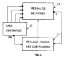
- Figure 4 illustrates the method of learning a neural network intended to be integrated in the device of figure 3.
- FIG. 5 represents a protection device according to a second embodiment, for a three-phase transformer.
- a differential protection device for a transformer T includes a processing circuit 5, a current sensor 3 for measuring the primary current It supplied to a primary winding 1 of the transformer by a power supply line L, a current sensor 4 for measuring a secondary current I2 leaving a winding secondary 2 of the transformer and a device 6 for interrupting the power supply of the transformer.
- the two current sensors 3 and 4 are connected to inputs of the processing circuit which provides a trip order 7 to the interrupt device 6 if certain trigger conditions are checked.
- the circuit of processing can also be connected to a fault signaling circuit 8.
- differential protection devices The most common faults detected by differential protection devices are: insulation or short-circuit faults between turns of the primary windings or secondary or between turns and transformer masses.
- Figure 2 shows a diagram of a faulty transformer.
- Current I1 crosses the primary winding 1 comprising a number of turns N1 and the current I2 is generated in the secondary winding 2 comprising a number of turns N2. Both windings are wound on a magnetic circuit 9.
- a fault of the primary winding is modeled by a resistive short circuit 10 between a turn and a winding end 1.
- Differential protection consists in detecting a differential current Id and in triggering the device if certain triggering conditions are verified.
- must be greater than a fraction K of the absolute value of the holding current
- the current differential is also compared to a threshold Im.
- are processed to keep only the fundamental component defined by the frequency of the current and the line voltage power supply, for example 50 Hz, or 60 Hz.
- trigger condition 3 is not sufficient to ensure correct operation of the device.
- the magnetic circuit can become saturated. This saturation causes the appearance of a transient differential current which can trigger the device when there is no fault.
- the various operating cases can be identified using a spectral analysis of the currents I1, I2 or the differential current Id.
- the overall treatment of the protection is not easy to obtain in a practical way with electronic circuits classic analog or digital.
- the protection device includes a sampling circuit 11 connected to the current sensors 3 and 4, a circuit preprocessing 12 connected to the sampling circuit 11 and a network 13 of neurons comprising four inputs E1, E2, E3, E4 connected to the preprocessing circuit.
- Output S of the neural network is connected to a relay 14 which causes the opening of the device 6.
- the output S can also be connected to a display device 15.
- the sampling circuit 11 samples with a sampling period Te, signals representative of the primary I1 and secondary I2 currents, and provides the samples to the preprocessing circuit 12.
- the samples of the signals of the currents I1 and I2 are used to calculate the differential current Id and the holding current Ir according to the expressions 1 and 2.
- Circuit 12 performs a spectral analysis of the signals according to a sliding window method. At each sampling period Te, a set of last samples collected during a period T1 corresponding to the duration of the window, is used for spectral analysis.
- the period T1 is equivalent to the period of the fundamental frequency of the current I1 supplied to the transformer, for example 50 or 60 Hz.
- the spectral analysis performed by the circuit 12 determines signals representative of the fundamental component H1D of the differential current, of the component of the second H2D harmonic (100 Hz or 120 Hz) of the differential current, of the component of the fifth harmonic H5D (250 Hz or 300 Hz) of the differential current and the fundamental component H1R of the holding current.
- the signals can, in a first embodiment, be applied to the inputs of the neural network.
- the input E1 then receives a signal representative of HD1, the input E2 a signal representative of HD2, input E3 a signal representative of H5D and input E4 a signal representative of H1R.
- the preprocessing circuit 12 then supplies on the input El a signal representative of the ratio H1D / H1R, on input E2 a signal representative of the H1D / In ratio, on input E3 a signal representative of the H2D / H1D ratio and on input E4 a signal representative of the H5D / H1D ratio.
- the neural network receives the input signals and determines the value of the output S as a function of situations learned during a learning phase. In actual operation the network must differentiate between healthy and faulty situations to give rise to a trigger.
- the neural network 13 of the multilayer perceptron type comprises three layers of neurons.
- a first layer 16 includes neurons connected to the inputs of the network 13.
- a second layer 17 constitutes an internal layer and a third layer 18 is connected to the output.
- the neurons of the second layer are connected to the neurons of the first and third layer.
- the network 16 has three neurons in the first layer, two neurons in the second layer and a neuron in the third layer.
- Each neuron has coefficients configured during a learning cycle where the main operating and fault situations are presented.
- Neural network output is defined for values located between -1 and 1. During learning, healthy situations are characterized by a output value around -0.8 and fault situations by values close to +0.8. In actual operation, positive values, from the output of the neural network, give a trigger order.
- FIG. 4 shows an automated learning of a network 13 of neurons that can be used in the differential protection device of Figure 3.
- a base of examples 20 includes all the situations that the network 13 must learn. For each situation, the base contains the values of the four signals applied to the inputs and the value of a corresponding reference SR output.
- the output S of the neural network and the reference output SR of the example base are connected to a regulating device 21 coefficients of neurons.
- the device 21 compares the two outputs and sets the coefficients so as to obtain a value of the output S of the network as close as possible of the value of the SR reference output. Examples base situations are used sequentially and / or simultaneously for learning the neural network.
- the examples are chosen so that the neural network can detect a fault situation within a maximum of 20 ms after the appearance of a fault.
- FIG. 3 given by way of example, is used with a transformer single phase or with the windings of a phase of a transformer polyphase.
- a device for differential protection is used for a three-phase transformer T3.
- Three sensors 3a, 3b, 3c of current measure primary currents I1a, I1b, I1c of three phases a, b and c supplying the three-phase primary winding 31.
- Three sensors 4a, 4b, 4c measure currents I2a, I2b, I2c leaving a three-phase secondary winding 32.
- the sensors current are connected to a sampling circuit 22.
- An output of circuit 22 is connected to a preprocessing circuit 23 which performs a spectral analysis and calculates the differential currents and holding currents.
- a neural network 24 includes inputs connected to circuit 23, an output S connected to a trigger relay 14 and auxiliary outputs S1, S2, S3, S4, S5 connected to a signaling circuit 25.
- the differential protection device described above can be applied to any type of electrical transformer whatever the primary voltages and currents or secondary as well as the coupling of primary or secondary windings.
- the power cut-off devices can be connected as well to the primary windings and to the secondary windings of the transformer.
- the pretreatment circuits 12 and 23 develop, in the above embodiments, signals representative of the holding current and the fundamental component, of Harmonic 2 and Harmonic 5 of the differential current, but other signals can also be used to supplement differential protection.
- neural networks 13 and 24 are not limited to those mentioned above, they can be adapted to particular uses depending on the transformer used.
- the sensors used by the above devices are current sensors only, but it is also possible to add other sensors to refine the protection.
- the devices can be supplemented by adding sensors to measure the primary and secondary voltages or pressure temperature measurement sensors or gas evolution inside the transformer.
- differential protection device can be done so independent as in the embodiments described above or be integrated and associated with other types of protection such as overload protection or external short circuit.
Description
L'invention concerne un dispositif de protection différentielle d'un transformateur de puissance comportant des premiers moyens de mesure pour mesurer le courant circulant dans un enroulement primaire du transformateur, des seconds moyens de mesure pour mesurer le courant circulant dans un enroulement secondaire du transformateur, des moyens d'interruption connectés sur l'enroulement primaire du transformateur pour interrompre l'alimentation électrique du transformateur et un circuit de traitement connecté, aux premiers et seconds moyens de mesure, fournissant un signal de déclenchement aux moyens d'interruption et/ou des signaux d'information à des moyens de signalisation ou de contrôle, le circuit de traitement comportant des moyens d'échantillonnage connectés aux premiers et seconds moyens de mesure pour échantillonner des signaux représentatifs des courants mesurés dans les enroulements primaires et secondaires et des moyens de prétraitement connectés aux moyens d'échantillonage pour fournir des signaux représentatifs de la composante fondamentale, de la deuxième harmonique et de la cinquième harmonique d'un courant différentiel et un signal représentatif d'un courant de retenue.The invention relates to a differential protection device of a transformer power comprising first measuring means for measuring the circulating current in a primary winding of the transformer, second measurement means for measure the current flowing in a secondary winding of the transformer, means connected to the primary winding of the transformer to interrupt the transformer power supply and a processing circuit connected to the first and second measuring means, providing a trigger signal to the means of interruption and / or information signals to signaling or control, the processing circuit comprising sampling means connected to the first and second measurement means for sampling signals representative of the currents measured in primary and secondary windings and preprocessing means connected to the sampling means for supplying signals representative of the fundamental component, the second harmonic and the fifth harmonic of a differential current and a signal representative of a holding current.
Les dispositifs de protection différentielle connus analysent les courants des enroulements primaires et secondaires des transformateurs. Le but des protections différentielles est de détecter un défaut interne entre deux spires quelconques des enroulements du transformateur ou un défaut entre une spire et la masse du transformateur. Les défauts sont détectés par la mesure d'un courant différentiel représentatif de la différence de courant entre le courant circulant dans les enroulements primaires et le courant circulant dans les enroulements secondaires, en tenant compte du rapport de transformation et du couplage. On utilise également un courant de retenue, appelé aussi courant traversant, représentatif d'une valeur moyenne entre les courants circulant dans les enroulements primaires et secondaires, au rapport de transformation et au couplage près.Known differential protection devices analyze the winding currents primary and secondary transformers. The purpose of the differential protections is to detect an internal fault between any two turns of the transformer windings or a fault between a turn and the mass of the transformer. Faults are detected by the measurement of a differential current representative of the current difference between the current flowing through primary windings and current flowing through windings secondary, taking into account the transformation ratio and the coupling. We use also a holding current, also called through current, representative of a value average between the currents flowing in the primary and secondary windings, at transformation ratio and close coupling.
La protection différentielle utilisée dans des relais de déclenchement provoque la coupure d'une alimentation électrique connectée à l'enroulement primaire du transformateur. Généralement un ordre de déclenchement est produit si des conditions de déclenchement sont vérifiées, par exemple lorsque le courant différentiel est supérieur à un seuil prédéterminé ou lorsqu'il dépasse une fraction du courant de retenue.Differential protection used in trip relays causes breaking an electrical power supply connected to the primary winding of the transformer. Generally a trigger order is generated if trigger conditions are checked, for example when the differential current is greater than a threshold predetermined or when it exceeds a fraction of the holding current.
Les seules conditions de déclenchement ne suffisent pas à assurer un fonctionnement correct des dispositifs de protection différentielle. Lors de la mise sous tension, notamment, un flux rémanent dans un circuit magnétique du transformateur peut provoquer une saturation du circuit magnétique selon la phase d'enclenchement de la tension d'alimentation et fournir des mesures de courants différentiels transitoires très élevés. En fonctionnement permanent à forts niveaux de tension le circuit magnétique du transformateur peut également se saturer et fausser la mesure du courant différentiel. Dans certains dispositifs, des moyens de mesure des courants primaires et secondaires comportent un circuit magnétique qui sature à forts niveaux de courants et fournissent des mesures erronnées.The trigger conditions alone are not sufficient to ensure correct operation differential protection devices. During power-up, in particular, a flow residual in a magnetic circuit of the transformer can cause saturation of the magnetic circuit according to the switching on phase of the supply voltage and supply very high transient differential current measurements. In permanent operation at high voltage levels the magnetic circuit of the transformer can also become saturated and falsify the measurement of the differential current. In some devices, measuring means primary and secondary currents have a magnetic circuit which saturates at high current levels and provide erroneous measurements.
Des relais électroniques classiques comportant des circuits analogiques ou numériques, permettent d'identifier certains régimes transitoires ou permanents, représentant des évènements autres que des défauts mais générant cependant un courant différentiel dû par exemple à la saturation du circuit magnétique du transformateur ou des capteurs de mesure, afin d'éviter des déclenchements intempestifs. L'article de Murty et al. "A KALMAN FILTER BASED DIGITAL PERCENTAGE DIFFERENTIAL AND GROUND FAULT RELAY FOR A 3-PHASE POWER TRANSFORMER" publié dans IEEE TRANSACTIONS ON POWER DELIVERY, vol. 5, no. 3, juillet 1990 divulgue un dispositif de protection différentielle d'un transformateur de puissance conforme au préambule de la revendication 1. Les moyens de traitement de ce dispositif connu utilisent une logique pour élaborer les signaux fournis par le circuit de pré-traitement. Cependant une prise en compte complète de tous les cas de fonctionnement conduirait à des circuits ou des algorithmes très complexes et coûteux, et/ou à des temps de réponse trop élevés, pour une protection différentielle efficace des transformateurs.Conventional electronic relays with analog or digital circuits, identify certain transitional or permanent regimes, representing events other than faults but generating however a differential current due to example at saturation of the magnetic circuit of the transformer or of the measurement sensors, in order to avoid nuisance trips. The article by Murty et al. "A KALMAN FILTER BASED DIGITAL PERCENTAGE DIFFERENTIAL AND GROUND FAULT RELAY FOR A 3-PHASE POWER TRANSFORMER "published in IEEE TRANSACTIONS ON POWER DELIVERY, vol. 5, no. 3, July 1990 discloses a differential protection device of a power transformer in accordance with the preamble to the claim 1. The means of processing this known device use logic to develop the signals provided by the pre-processing circuit. However, taking full account of all operating cases would lead to very complex circuits or algorithms and expensive, and / or with too long response times, for differential protection efficient transformers.
L'article de Chan Tat-Wai et al. "DETECTION OF MAGNETIZING INRUSH CURRENT USING ARTIFICIAL NEURAL NETWORK" publié dans PROCEEDINGS TENCON '93, vol. 2, octobre 1993 divulgue l'utilisation d'un réseau de neurones recevant en entrée des échantillons du courant circulant dans le primaire d'un transformateur (notamment de la fondamentale, de la deuxième et de la troisième harmonique de ce courant) et comportant une sortie logique pour indiquer la présence d'un courant transitoire de magnétisation.The article by Chan Tat-Wai et al. "DETECTION OF MAGNETIZING INRUSH CURRENT USING ARTIFICIAL NEURAL NETWORK "published in PROCEEDINGS TENCON '93, vol. 2, October 1993 discloses the use of a network of neurons receiving current samples as input circulating in the primary of a transformer (including the fundamental, the second and the third harmonic of this current) and comprising a logic output to indicate the presence of current transient magnetization.
L'invention a pour but un dispositif de protection différentielle pour transformateur rapide et peu coûteux pouvant différencier un nombre important de situations de fonctionnement et de conditions de déclenchement.The object of the invention is a differential protection device for a fast transformer. and inexpensive can differentiate a large number of operating situations and trigger conditions.
Ce but est atteint par le fait que le circuit de traitement comporte un réseau de neurones comportant des entrées connectées aux moyens de prétraitement et au moins une sortie pour fournir les signaux de déclenchement et/ou d'information, le réseau de neurones recevant sur ses entrées les signaux représentatifs de la composante fondamentale, de la deuxième harmonique et de la cinquième harmonique d'un courant différentiel et le signal représentatif d'un courant de retenue fournis par les moyens de prétraitement.This object is achieved by the fact that the processing circuit comprises a neural network comprising inputs connected to the preprocessing means and at least one output to provide the trigger and / or information signals, the neural network receiving on its inputs the signals representative of the fundamental component, of the second harmonic and fifth harmonic of a differential current and the signal representative of a holding current supplied by the pretreatment means.
Selon un développement de l'invention les moyens de prétraitement fournissent au réseau de neurones des signaux représentatifs :
- du rapport entre la composante fondamentale du courant différentiel et la composante fondamentale du courant de retenue,
- du rapport entre la composante fondamentale du courant différentiel et la valeur d'un signal représentatif d'un courant nominal,
- du rapport entre la deuxième harmonique du courant différentiel et la composante fondamentale du courant différentiel,
- du rapport entre la cinquième harmonique du courant différentiel et la composante fondamentale du courant différentiel.
- the ratio between the fundamental component of the differential current and the fundamental component of the holding current,
- the ratio between the fundamental component of the differential current and the value of a signal representative of a nominal current,
- the relationship between the second harmonic of the differential current and the fundamental component of the differential current,
- of the relationship between the fifth harmonic of the differential current and the fundamental component of the differential current.
Dans un mode préférentiel de réalisation le réseau de neurones est de type perceptron multicouches comportant trois couches de neurones, quatre entrées par phase de courant à contrôler et une sortie de signal de déclenchement et/ou de signalisation, les quatre entrées étant connectées à une première couche comportant trois neurones, la sortie étant connectée à une troisième couche comportant un neurone, une seconde couche comportant deux neurones étant connectée à la première et à la troisième couche.In a preferred embodiment, the neural network is of the perceptron type. multilayer with three layers of neurons, four inputs per phase of current to control and a trigger signal and / or signaling output, the four inputs being connected to a first layer comprising three neurons, the output being connected to a third layer comprising a neuron, a second layer comprising two neurons being connected to the first and third layers.
Les neurones du réseau de neurones comportent des coefficients calculés pendant un cycle d'apprentissage, les valeurs des signaux appliqués sur les entrées du réseau de neurones étant représentatives de situations de défaut interne, de situations de défaut externe, de situations de fonctionnement normal et de situations de mise sous tension du transformateur.Neurons in the neural network have coefficients calculated during a cycle the values of the signals applied to the inputs of the neural network being representative of internal default situations, external default situations, normal operating situations and transformer power-up situations.
Selon un mode particulier de réalisation, le réseau de neurones comporte au moins une sortie de signalisation pour signaler la présence d'un défaut interne entre spires d'un enroulement du transformateur, d'un défaut interne entre une spire d'un enroulement et une masse du transformateur et/ou d'un défaut externe.According to a particular embodiment, the neural network comprises at least one signaling output to signal the presence of an internal fault between turns of a transformer winding, an internal fault between a turn of a winding and a mass of the transformer and / or an external fault.
D'autres avantages et caractéristiques ressortiront plus clairement de la description qui va suivre, de modes particuliers de réalisation de l'invention, donnés à titre d'exemples non limitatifs et représentés aux dessins annexés sur lesquels :Other advantages and characteristics will emerge more clearly from the description which follows. follow, particular embodiments of the invention, given by way of examples not limiting and shown in the accompanying drawings in which:
La figure 1 représente un schéma bloc d'un dispositif de protection différentielle de transformateur de type connu.FIG. 1 represents a block diagram of a differential protection device for known type transformer.
La figure 2 montre la modélisation d'un défaut dans un transformateur.Figure 2 shows the modeling of a fault in a transformer.
La figure 3 représente un dispositif de protection selon un premier mode de réalisation de l'invention, pour un transformateur monophasé.FIG. 3 represents a protection device according to a first embodiment of the invention, for a single-phase transformer.
La figure 4 illustre la méthode d'apprentissage d'un réseau de neurones destiné à être intégré dans le dispositif de la figure 3. Figure 4 illustrates the method of learning a neural network intended to be integrated in the device of figure 3.
La figure 5 représente un dispositif de protection selon un second mode de réalisation, pour un transformateur triphasé.FIG. 5 represents a protection device according to a second embodiment, for a three-phase transformer.
Sur la figure 1 un dispositif de protection différentielle d'un transformateur T comporte un
circuit 5 de traitement, un capteur de courant 3 pour mesurer le courant primaire Il fourni à
un enroulement primaire 1 du transformateur par une ligne L d'alimentation électrique, un
capteur de courant 4 pour mesurer un courant secondaire I2 sortant d'un enroulement
secondaire 2 du transformateur et un dispositif 6 d'interruption de l'alimentation électrique
du transformateur. Les deux capteurs de courant 3 et 4 sont connectés à des entrées du
circuit de traitement qui fournit un ordre de déclenchement 7 au dispositif 6 d'interruption
si certaines conditions de déclenchement sont vérifiées. Le dispositif 6 , connecté entre la
ligne d'alimentation L et l'enroulement primaire 1 du transformateur, interrompt par
l'ouverture de contacts la circulation du courant dans le transformateur 1. Le circuit de
traitement peut aussi être connecté à un circuit 8 de signalisation de défaut.In FIG. 1, a differential protection device for a transformer T includes a
Les défauts les plus courants détectés par les dispositifs de protection différentielle sont les défauts d'isolement ou de court-circuit entre des spires des enroulements primaires ou secondaires ou entre des spires et des masses du transformateur.The most common faults detected by differential protection devices are: insulation or short-circuit faults between turns of the primary windings or secondary or between turns and transformer masses.
La figure 2 montre un schéma d'un transformateur en défaut. Le courant I1 traverse
l'enroulement primaire 1 comportant un nombre de spires N1 et le courant I2 est généré
dans l'enroulement secondaire 2 comportant un nombre de spires N2. Les deux
enroulements sont bobinés sur un circuit magnétique 9. Sur le schéma un défaut de
l'enroulement primaire est modélisé par un court-circuit résistif 10 entre une spire et une
extrémité de l'enroulement 1.Figure 2 shows a diagram of a faulty transformer. Current I1 crosses
the primary winding 1 comprising a number of turns N1 and the current I2 is generated
in the
La protection différentielle consiste à détecter un courant différentiel Id et à faire déclencher
le dispositif si certaines conditions de déclenchement sont vérifiées. L'expression du courant
différentiel est :
Le courant différentiel est comparé à un courant de retenue Ir appelé aussi courant
traversant, l'expression du courant de retenue est :
Selon une des conditions de déclenchement la valeur absolue du courant différentiel |Id| doit être supérieure à une fraction K de la valeur absolue du courant de retenue |Ir|. Pour éviter de détecter des défauts aléatoires à faibles niveaux de courant de retenue, le courant différentiel est également comparé à un seuil Im.According to one of the triggering conditions, the absolute value of the differential current | Id | must be greater than a fraction K of the absolute value of the holding current | Ir |. For avoid detecting random faults at low levels of holding current, the current differential is also compared to a threshold Im.
L'expression des conditions de déclenchement est donnée par :
Les grandeurs des courants |Id| et |Ir| sont traitées de manière à garder seulement la composante fondamentale définie par la fréquence du courant et de la tension de la ligne d'alimentation, par exemple 50 Hz, ou 60 Hz.The magnitudes of the currents | Id | and | Ir | are processed to keep only the fundamental component defined by the frequency of the current and the line voltage power supply, for example 50 Hz, or 60 Hz.
Dans des cas particuliers de fonctionnement, la condition de déclenchement 3 n'est pas
suffisante pour assurer un fonctionnement correct du dispositif. Lors de la mise sous tension
du transformateur, selon la valeur d'un flux rémanent dans le circuit magnétique 9 et la
phase d'enclenchement d'une tension dans l'enroulement primaire, le circuit magnétique
peut se saturer. Cette saturation entraíne l'apparition d'un courant différentiel transitoire qui
peut faire déclencher le dispositif alors qu'il n'y a pas de défaut. Certains dispositifs connus
bloquent le déclenchement pendant un temps prédéterminé à la mise sous tension.
Cependant cette solution conduit à un retard de traitement dommageable, si le
transformateur a un défaut.In special operating cases,
En régime établi, un défaut externe peut entraíner une augmentation de la tension et saturer
le circuit magnétique. La saturation introduit une mesure fausse du courant différentiel sans
défaut interne dans le transformateur. L'augmentation du courant au-delà du courant
nominal du transformateur affecte également la linéarité des capteurs 3 et 4 de courant. Les
capteurs, généralement constitués par des transformateurs de courant, ont un circuit
magnétique qui se sature lorsque le courant à mesurer augmente.In steady state, an external fault can cause an increase in voltage and saturate
the magnetic circuit. Saturation introduces a false measurement of the differential current without
internal fault in the transformer. Increasing the current beyond the current
transformer rating also affects the linearity of
Les divers cas de fonctionnement peuvent être identifiés à l'aide d'une analyse spectrale des courants I1, I2 ou du courant différentiel Id. Cependant, le traitement global de la protection n'est pas facile à obtenir de manière pratique avec des circuits électroniques analogiques ou numériques classiques.The various operating cases can be identified using a spectral analysis of the currents I1, I2 or the differential current Id. However, the overall treatment of the protection is not easy to obtain in a practical way with electronic circuits classic analog or digital.
Dans un premier mode de réalisation de l'invention (figure 3), le dispositif de protection
comporte un circuit d'échantillonnage 11 connecté aux capteurs 3 et 4 de courant, un circuit
de prétraitement 12 connecté au circuit d'échantillonnage 11 et un réseau 13 de neurones
comportant quatre entrées E1, E2, E3, E4 connectées au circuit de prétraitement. Une sortie
S du réseau de neurones est connectée à un relais 14 qui provoque l'ouverture du dispositif
d'interruption 6. La sortie S peut être aussi connectée à un dispositif d'affichage 15.
Le circuit d'échantillonnage 11 échantillonne avec une période d'échantillonnage Te, des
signaux représentatifs des courants primaires I1 et secondaires I2, et fournit les échantillons
au circuit de prétraitement 12. Les échantillons des signaux des courants I1 et I2 sont
utilisés pour calculer le courant différentiel Id et le courant de retenue Ir selon les
expressions 1 et 2. Le circuit 12 effectue une analyse spectrale des signaux selon une
méthode de fenêtre glissante. A chaque période d'échantillonnage Te, un ensemble des
derniers échantillons recueillis pendant une période T1 correspondant à la durée de la
fenêtre, est utilisé pour l'analyse spectrale. La période T1 est équivalente à la période de la
fréquence fondamentale du courant I1 fourni au transformateur par exemple 50 ou 60 Hz.
L'analyse spectrale effectuée par le circuit 12 détermine des signaux représentatifs de la
composante fondamentale H1D du courant différentiel, de la composante de la seconde
harmonique H2D (100 Hz ou 120 Hz) du courant différentiel, de la composante de la
cinquième harmonique H5D (250 Hz ou 300 Hz) du courant différentiel et de la
composante fondamentale H1R du courant de retenue.In a first embodiment of the invention (Figure 3), the protection device
includes a
Les signaux peuvent, dans un premier mode de réalisation, être appliqués sur les entrées du réseau de neurones. L'entrée E1 reçoit alors un signal représentatif de HD1, l'entrée E2 un signal représentatif de HD2, l'entrée E3 un signal représentatif de H5D et l'entrée E4 un signal représentatif de H1R.The signals can, in a first embodiment, be applied to the inputs of the neural network. The input E1 then receives a signal representative of HD1, the input E2 a signal representative of HD2, input E3 a signal representative of H5D and input E4 a signal representative of H1R.
Cependant, dans d'autres modes de réalisation, un premier calcul élaboré dans le circuit 12 permet de combiner les signaux H1D, H2D, H5D, et H1R de manière à caractériser efficacement les grandeurs des signaux. Dans un mode de réalisation préférentiel, le circuit de prétraitement effectue les combinaisons suivantes :
- Un calcul du rapport de la composante fondamentale H1D du courant différentiel sur la
composante fondamentale H1R du courant de retenue
- Un calcul du rapport de la composante fondamentale H1D du courant différentiel sur un
signal représentatif In d'un courant nominal du transformateur
- Un calcul du rapport de la seconde harmonique H2D sur la composante fondamentale du
courant différentiel
- Un calcul du rapport de la cinquième harmonique H5D sur la composante fondamentale
du courant différentiel
- A calculation of the ratio of the fundamental component H1D of the differential current to the fundamental component H1R of the holding current
- A calculation of the ratio of the fundamental component H1D of the differential current to a signal representative In of a nominal current of the transformer
- A calculation of the ratio of the second harmonic H2D on the fundamental component of the differential current
- A calculation of the ratio of the fifth harmonic H5D on the fundamental component of the differential current
Le circuit 12 de prétraitement fournit alors sur l'entrée El un signal représentatif du rapport
H1D/H1R, sur l'entrée E2 un signal représentatif du rapport H1D/In, sur l'entrée E3 un
signal représentatif du rapport H2D/H1D et sur l'entrée E4 un signal représentatif du
rapport H5D/H1D. Le réseau de neurones reçoit les signaux d'entrée et détermine la valeur
de la sortie S en fonction de situations apprises lors d'une phase d'apprentissage. En
fonctionnement réel le réseau doit différencier des situations saines des situations en défaut
devant donner lieu à un déclenchement.The
Le réseau de neurones 13 de type perceptron multicouches comporte trois couches de
neurones. Une première couche 16 comporte des neurones connectées aux entrées du réseau
13. Une seconde couche 17 constitue une couche interne et une troisième couche 18 est
connectée à la sortie. Les neurones de la seconde couche sont connectés aux neurones de la
première et de la troisième couche. Dans le mode de réalisation de la figure 3, le réseau 16
comporte trois neurones dans la première couche, deux neurones dans la seconde couche et
un neurone dans la troisième couche. Chaque neurone a des coefficients paramétrés lors d'un
cycle d'apprentissage où les principales situations de fonctionnement et de défaut sont
présentées.The
Dans le cas d'une protection différentielle de transformateur, une situation est considérée comme un défaut si elle représente un défaut interne du transformateur. Les autres situations sont considérées comme des situations saines même si des défauts externes peuvent se présenter. La sortie du réseau de neurones est définie pour des valeurs situées entre -1 et 1. Au cours de l'apprentissage les situations saines sont caractérisées par une valeur de sortie aux environs de -0,8 et les situations en défaut par des valeurs voisines de +0,8. En fonctionnement réel, des valeurs positives, de la sortie du réseau de neurones, donnent un ordre de déclenchement.In the case of transformer differential protection, a situation is considered as a fault if it represents an internal fault of the transformer. Others situations are considered healthy situations even if external faults can come up. Neural network output is defined for values located between -1 and 1. During learning, healthy situations are characterized by a output value around -0.8 and fault situations by values close to +0.8. In actual operation, positive values, from the output of the neural network, give a trigger order.
Pendant l'apprentissage du réseau de neurones, des signaux représentatifs du courant de
retenue et du courant différentiel, notamment les signaux H1D/H1R, H1D/In, H2D/H1D et
H5D/H1D, sont appliqués sur les entrées. Les coefficients des neurones du réseau sont alors
modifiés de manière à ce que la valeur de la sortie du réseau soit la plus proche de la valeur
d'une sortie de référence correspondant à la situation définie par les valeurs des signaux
d'entrée. L'apprentissage se fait à partir de plusieurs cas de fonctionnement et de défaut
présentés plusieurs fois. La figure 4 montre un apprentissage automatisé d'un réseau 13 de
neurones pouvant être utilisé dans le dispositif de protection différentielle de la figure 3.
Une base d'exemples 20 comporte toutes les situations que le réseau 13 doit apprendre.
Pour chaque situation, la base comporte les valeurs des quatre signaux appliqués aux entrées
et la valeur d'une sortie SR de référence correspondante. La sortie S du réseau de neurones
et la sortie SR de référence de la base d'exemples sont reliées à un dispositif 21 de réglage
des coefficients des neurones. Le dispositif 21 compare les deux sorties et paramètre les
coefficients de manière à obtenir une valeur de la sortie S du réseau la plus proche possible
de la valeur de la sortie de référence SR. Les situations de la base d'exemples sont utilisées
séquentiellement et/ou simultanément pour l'apprentissage du réseau de neurones.During the learning of the neural network, signals representative of the current
carry and differential current, including H1D / H1R, H1D / In, H2D / H1D and
H5D / H1D, are applied to the inputs. The coefficients of the neurons in the network are then
changed so that the value of the network output is closest to the value
a reference output corresponding to the situation defined by the values of the signals
entry. Learning takes place from several operating and fault cases
presented several times. FIG. 4 shows an automated learning of a
La base d'exemples 20 comporte environ mille exemples de situations différentes. Ces situations peuvent être répertoriées en plusieurs classes, par exemple :
- le fonctionnement normal, à vide ou en charge,
- la mise sous tension du transformateur,
- défaut extérieur,
- défaut interne entre spires,
- défaut interne entre une spire et une masse.
- normal operation, empty or under load,
- energizing the transformer,
- external fault,
- internal fault between turns,
- internal fault between a turn and a mass.
Les exemples sont choisis de manière à ce que le réseau de neurones puisse détecter une situation en défaut dans un délai maximum de 20 ms après l'apparition d'un défaut.The examples are chosen so that the neural network can detect a fault situation within a maximum of 20 ms after the appearance of a fault.
Le mode de réalisation de la figure 3, donné à titre d'exemple, est utilisé avec un
transformateur T monophasé ou avec les enroulements d'une phase d'un transformateur
polyphasé. Dans un autre mode de réalisation, représenté sur la figure 5, un dispositif de
protection différentielle est utilisé pour un transformateur triphasé T3. Trois capteurs 3a,
3b, 3c de courant mesurent des courants primaires I1a, I1b, I1c de trois phases a, b et c
alimentant l'enroulement 31 primaire triphasé. Trois capteurs 4a, 4b, 4c mesurent des
courants I2a, I2b, I2c sortant d'un enroulement 32 secondaire triphasé. Les capteurs de
courant sont connectés à un circuit 22 d'échantillonnage. Une sortie du circuit 22 est
connectée à un circuit 23 de prétraitement qui effectue une analyse spectrale et calcule les
courant différentiels et les courants de retenue. Un réseau de neurones 24 comporte des
entrées connectées au circuit 23, une sortie S connectée à un relais 14 de déclenchement et
des sorties auxiliaires S1, S2, S3, S4, S5 connectées à un circuit 25 de signalisation. The embodiment of FIG. 3, given by way of example, is used with a
transformer single phase or with the windings of a phase of a transformer
polyphase. In another embodiment, represented in FIG. 5, a device for
differential protection is used for a three-phase transformer T3. Three
Le circuit de prétraitement 23 peut élaborer les mêmes signaux que le circuit 12 de la figure 3 pour chacune des trois phases du transformateur T3 ou effectuer d'autres combinaisons des signaux représentatifs des composantes fondamentales ou harmoniques des courants différentiels ou de retenue. De la même manière le réseau de neurones 24 peut comporter trois répliques du réseau 13 en parallèle ou comporter une organisation globale différente tenant compte de l'ensemble des signaux des entrées. Dans le mode de réalisation de la figure 5, le réseau 24 fournit sur ses sorties auxiliaires S1 à S5 des informations sur la présence et la nature d'un défaut détecté pour chacune des phases du transformateur. Le circuit 25 de signalisation signale séparément alors les situations détectées par le réseau de neurones par exemple les situations de défaut suivantes :
- défaut entre spires au primaire, phase a, b et/ou c,
- défaut entre spires au secondaire, phase a, b et/ou c,
- défaut entre une spire et une masse au primaire, phase a, b et/ou c,
- défaut entre une spire et une masse au secondaire, phase a, b et/ou c,
- mise sous tension,
- fonctionnement normal,
- défaut externe, phase a, b et/ou c.
- fault between turns in primary, phase a, b and / or c,
- fault between turns in secondary, phase a, b and / or c,
- fault between a turn and a mass in primary, phase a, b and / or c,
- fault between a turn and a secondary mass, phase a, b and / or c,
- power up,
- normal running,
- external fault, phase a, b and / or c.
Le dispositif de protection différentielle décrit ci-dessus peut s'appliquer à tout type de transformateur électrique quels que soient les tensions et les courants primaires ou secondaires ainsi que le couplage des enroulements primaires ou secondaires. Dans les réseaux maillés les dispositifs de coupure d'alimentation peuvent être aussi bien raccordés aux enroulements primaires et aux enroulements secondaires du transformateur.The differential protection device described above can be applied to any type of electrical transformer whatever the primary voltages and currents or secondary as well as the coupling of primary or secondary windings. In the mesh networks the power cut-off devices can be connected as well to the primary windings and to the secondary windings of the transformer.
Les circuits de prétraitement 12 et 23 élaborent, dans les modes de réalisation ci-dessus, des
signaux représentatifs du courant de retenue et de la composante fondamentale, de
l'harmonique 2 et de l'harmonique 5 du courant différentiel, mais d'autres signaux peuvent
également être utilisés pour compléter la protection différentielle.The
Les situations identifiées par les réseaux de neurones 13 et 24 ne sont pas limitées à celles
citées ci-dessus, elles peuvent être adaptées à des usages particuliers selon le transformateur
utilisé. The situations identified by
Les capteurs utilisés par les dispositifs ci-dessus sont des capteurs de courant uniquement, mais il est également possible d'ajouter d'autres capteurs pour affiner la protection. Par exemple les dispositifs peuvent être complétés en ajoutant des capteurs pour mesurer les tensions primaires et secondaires ou des capteurs de mesure de température de pression ou de dégagement gazeux à l'intérieur du transformateur.The sensors used by the above devices are current sensors only, but it is also possible to add other sensors to refine the protection. By example the devices can be supplemented by adding sensors to measure the primary and secondary voltages or pressure temperature measurement sensors or gas evolution inside the transformer.
La mise en oeuvre du dispositif de protection différentielle peut être faite de manière indépendante comme dans les modes de réalisation décrits ci-dessus ou être intégrée et associée à d'autres types de protection comme par exemple la protection en surcharge ou de court-circuit externe.The implementation of the differential protection device can be done so independent as in the embodiments described above or be integrated and associated with other types of protection such as overload protection or external short circuit.
Claims (5)
- A protective device for differential protection of a power transformer comprising first measuring means (3; 3a, 3b, 3c) for measuring the current (I1; I1a, I1b, I1c) flowing in a primary winding (1; 31) of the transformer (T; T3), second measuring means (4; 4a, 4b, 4c) for measuring the current (I2; I2a, I2b, I2c) flowing in a secondary winding (2; 32) of the transformer (T; T3), interruption means (6, 14) connected to the primary winding of the transformer to interrupt the electrical power supply of the transformer, and a processing circuit (11, 12, 13; 22, 23, 24) connected to the first and second measuring means, supplying a tripping signal (S) to the interruption means (6, 14) and/or information signals to indicating or monitoring means (15; 25), the processing circuit comprising sampling means (11; 22) connected to the first and second measuring means to sample signals representative of the currents measured in the primary and secondary windings, and pre-processing means (12; 23) connected to the sampling means (11; 22) to supply signals representative of the fundamental component (H1D), of the second harmonic (H2D) and of the fifth harmonic (H5D) of a differential current and a signal (H1R) representative of a through current,
a device characterized in that the processing circuit comprises a neural network (13; 24) comprising inputs connected to the pre-processing means and at least one output (S) to supply the tripping and/or information signals, the neural network receiving on its inputs the signals representative of the fundamental component (H1D), of the second harmonic (H2D) and of the fifth harmonic (H5D) of a differential current and the signal (H1R) representative of a through current supplied by the pre-processing means. - The protective device according to claim 1 characterized in that the pre-processing means supply to the neural network signals representative :of the ratio (H1D/H1R) between the fundamental component of the differential current and the fundamental component of the through current,of the ratio (H1D/In) between the fundamental component of the differential current and the value of a signal representative of a rated current (In),of the ratio (H2D/H1D) between the second harmonic of the differential current and the fundamental component of the differential current,
- The protective device according to one of the claims 1 and 2 characterized in that the neural network is of the perceptron type comprising three layers of neurons, four inputs (E1, E2, E3, E4) per current phase to be monitored and a tripping and/or indication signal output (S), the four inputs being connected to a first layer (16) comprising three neurons, the output being connected to a third layer (18) comprising one neuron, a second layer (17) comprising two neurons being connected to the first and third layers.
- The protective device according to any one of the claims 1 to 3 characterized in that the neurons of the neural network comprise coefficients computed during a leaming cycle, the values of the signals applied to the inputs of the neural network being representative of intemal fault situations, extemal fault situations, normal operating situations and transformer power-up situations.
- The protective device according to any one of the claims 1 to 4 characterized in that the neural network comprises at least one indicating output to indicate the presence of an intemal fault between tums of a winding of the transformer, of an internal fault between a tum of a winding and a ground of the transformer and/or of an external fault.
Applications Claiming Priority (3)
| Application Number | Priority Date | Filing Date | Title |
|---|---|---|---|
| FR9400143 | 1994-01-06 | ||
| FR9400143A FR2714771B1 (en) | 1994-01-06 | 1994-01-06 | Differential protection device for a power transformer. |
| PCT/FR1994/001531 WO1995019059A1 (en) | 1994-01-06 | 1994-12-26 | Device for differentially protecting a power transformer |
Publications (2)
| Publication Number | Publication Date |
|---|---|
| EP0738432A1 EP0738432A1 (en) | 1996-10-23 |
| EP0738432B1 true EP0738432B1 (en) | 1998-11-11 |
Family
ID=9458857
Family Applications (1)
| Application Number | Title | Priority Date | Filing Date |
|---|---|---|---|
| EP95905167A Expired - Lifetime EP0738432B1 (en) | 1994-01-06 | 1994-12-26 | Device for differentially protecting a power transformer |
Country Status (7)
| Country | Link |
|---|---|
| US (1) | US5784233A (en) |
| EP (1) | EP0738432B1 (en) |
| CN (1) | CN1047887C (en) |
| DE (1) | DE69414605T2 (en) |
| ES (1) | ES2127509T3 (en) |
| FR (1) | FR2714771B1 (en) |
| WO (1) | WO1995019059A1 (en) |
Families Citing this family (144)
| Publication number | Priority date | Publication date | Assignee | Title |
|---|---|---|---|---|
| IT1292453B1 (en) | 1997-07-02 | 1999-02-08 | Aeg Niederspannungstech Gmbh | ROTATING GROUP OF CONTACTS FOR HIGH FLOW SWITCHES |
| CN1057646C (en) * | 1997-10-15 | 2000-10-18 | 华中理工大学 | Virtual third harmonic blocking method for transformer microcomputer protection |
| DE19819242B4 (en) | 1998-04-29 | 2005-11-10 | Ge Power Controls Polska Sp.Z.O.O. | Thermomagnetic circuit breaker |
| US6114641A (en) | 1998-05-29 | 2000-09-05 | General Electric Company | Rotary contact assembly for high ampere-rated circuit breakers |
| US5959537A (en) * | 1998-07-09 | 1999-09-28 | Mcgraw-Edison Company | Variable trip fault indicator |
| US6247003B1 (en) * | 1998-08-13 | 2001-06-12 | Mcgraw-Edison Company | Current transformer saturation correction using artificial neural networks |
| US6087913A (en) | 1998-11-20 | 2000-07-11 | General Electric Company | Circuit breaker mechanism for a rotary contact system |
| US6037555A (en) | 1999-01-05 | 2000-03-14 | General Electric Company | Rotary contact circuit breaker venting arrangement including current transformer |
| US6166344A (en) | 1999-03-23 | 2000-12-26 | General Electric Company | Circuit breaker handle block |
| US6262872B1 (en) | 1999-06-03 | 2001-07-17 | General Electric Company | Electronic trip unit with user-adjustable sensitivity to current spikes |
| US6268991B1 (en) | 1999-06-25 | 2001-07-31 | General Electric Company | Method and arrangement for customizing electronic circuit interrupters |
| US6218917B1 (en) | 1999-07-02 | 2001-04-17 | General Electric Company | Method and arrangement for calibration of circuit breaker thermal trip unit |
| US6188036B1 (en) | 1999-08-03 | 2001-02-13 | General Electric Company | Bottom vented circuit breaker capable of top down assembly onto equipment |
| US6252365B1 (en) | 1999-08-17 | 2001-06-26 | General Electric Company | Breaker/starter with auto-configurable trip unit |
| US6710988B1 (en) | 1999-08-17 | 2004-03-23 | General Electric Company | Small-sized industrial rated electric motor starter switch unit |
| US6396369B1 (en) | 1999-08-27 | 2002-05-28 | General Electric Company | Rotary contact assembly for high ampere-rated circuit breakers |
| US6175288B1 (en) | 1999-08-27 | 2001-01-16 | General Electric Company | Supplemental trip unit for rotary circuit interrupters |
| US6232570B1 (en) | 1999-09-16 | 2001-05-15 | General Electric Company | Arcing contact arrangement |
| US6326869B1 (en) | 1999-09-23 | 2001-12-04 | General Electric Company | Clapper armature system for a circuit breaker |
| US6483680B1 (en) | 1999-10-13 | 2002-11-19 | General Electric Co. | Magnetizing inrush restraint method and relay for protection of power transformers |
| US6239395B1 (en) * | 1999-10-14 | 2001-05-29 | General Electric Company | Auxiliary position switch assembly for a circuit breaker |
| US6229413B1 (en) | 1999-10-19 | 2001-05-08 | General Electric Company | Support of stationary conductors for a circuit breaker |
| US6317018B1 (en) | 1999-10-26 | 2001-11-13 | General Electric Company | Circuit breaker mechanism |
| US6232856B1 (en) | 1999-11-02 | 2001-05-15 | General Electric Company | Magnetic shunt assembly |
| US6377144B1 (en) | 1999-11-03 | 2002-04-23 | General Electric Company | Molded case circuit breaker base and mid-cover assembly |
| EP1098343B1 (en) | 1999-11-03 | 2005-09-21 | AEG Niederspannungstechnik GmbH & Co. KG | Circuit breaker rotary contact arm arrangement |
| US6300586B1 (en) | 1999-12-09 | 2001-10-09 | General Electric Company | Arc runner retaining feature |
| US6310307B1 (en) | 1999-12-17 | 2001-10-30 | General Electric Company | Circuit breaker rotary contact arm arrangement |
| US6184761B1 (en) | 1999-12-20 | 2001-02-06 | General Electric Company | Circuit breaker rotary contact arrangement |
| US6172584B1 (en) | 1999-12-20 | 2001-01-09 | General Electric Company | Circuit breaker accessory reset system |
| US6215379B1 (en) | 1999-12-23 | 2001-04-10 | General Electric Company | Shunt for indirectly heated bimetallic strip |
| US6281461B1 (en) | 1999-12-27 | 2001-08-28 | General Electric Company | Circuit breaker rotor assembly having arc prevention structure |
| US6346869B1 (en) | 1999-12-28 | 2002-02-12 | General Electric Company | Rating plug for circuit breakers |
| US6211758B1 (en) | 2000-01-11 | 2001-04-03 | General Electric Company | Circuit breaker accessory gap control mechanism |
| US6239677B1 (en) | 2000-02-10 | 2001-05-29 | General Electric Company | Circuit breaker thermal magnetic trip unit |
| US6429759B1 (en) | 2000-02-14 | 2002-08-06 | General Electric Company | Split and angled contacts |
| US6281458B1 (en) | 2000-02-24 | 2001-08-28 | General Electric Company | Circuit breaker auxiliary magnetic trip unit with pressure sensitive release |
| US6313425B1 (en) | 2000-02-24 | 2001-11-06 | General Electric Company | Cassette assembly with rejection features |
| US6404314B1 (en) | 2000-02-29 | 2002-06-11 | General Electric Company | Adjustable trip solenoid |
| US6204743B1 (en) | 2000-02-29 | 2001-03-20 | General Electric Company | Dual connector strap for a rotary contact circuit breaker |
| US6340925B1 (en) | 2000-03-01 | 2002-01-22 | General Electric Company | Circuit breaker mechanism tripping cam |
| US6448521B1 (en) | 2000-03-01 | 2002-09-10 | General Electric Company | Blocking apparatus for circuit breaker contact structure |
| US6346868B1 (en) | 2000-03-01 | 2002-02-12 | General Electric Company | Circuit interrupter operating mechanism |
| US6379196B1 (en) | 2000-03-01 | 2002-04-30 | General Electric Company | Terminal connector for a circuit breaker |
| JP3389914B2 (en) * | 2000-03-03 | 2003-03-24 | 日本電気株式会社 | Sampling method and device for power supply current value of integrated circuit, and storage medium storing control program therefor |
| US6366438B1 (en) | 2000-03-06 | 2002-04-02 | General Electric Company | Circuit interrupter rotary contact arm |
| US6459349B1 (en) | 2000-03-06 | 2002-10-01 | General Electric Company | Circuit breaker comprising a current transformer with a partial air gap |
| US6211757B1 (en) | 2000-03-06 | 2001-04-03 | General Electric Company | Fast acting high force trip actuator |
| US6496347B1 (en) | 2000-03-08 | 2002-12-17 | General Electric Company | System and method for optimization of a circuit breaker mechanism |
| US6429659B1 (en) | 2000-03-09 | 2002-08-06 | General Electric Company | Connection tester for an electronic trip unit |
| US6218919B1 (en) | 2000-03-15 | 2001-04-17 | General Electric Company | Circuit breaker latch mechanism with decreased trip time |
| US6366188B1 (en) | 2000-03-15 | 2002-04-02 | General Electric Company | Accessory and recess identification system for circuit breakers |
| US6232859B1 (en) | 2000-03-15 | 2001-05-15 | General Electric Company | Auxiliary switch mounting configuration for use in a molded case circuit breaker |
| US6459059B1 (en) | 2000-03-16 | 2002-10-01 | General Electric Company | Return spring for a circuit interrupter operating mechanism |
| US6421217B1 (en) | 2000-03-16 | 2002-07-16 | General Electric Company | Circuit breaker accessory reset system |
| US6476698B1 (en) | 2000-03-17 | 2002-11-05 | General Electric Company | Convertible locking arrangement on breakers |
| US6373010B1 (en) | 2000-03-17 | 2002-04-16 | General Electric Company | Adjustable energy storage mechanism for a circuit breaker motor operator |
| US6388213B1 (en) | 2000-03-17 | 2002-05-14 | General Electric Company | Locking device for molded case circuit breakers |
| US6639168B1 (en) | 2000-03-17 | 2003-10-28 | General Electric Company | Energy absorbing contact arm stop |
| US6472620B2 (en) | 2000-03-17 | 2002-10-29 | Ge Power Controls France Sas | Locking arrangement for circuit breaker draw-out mechanism |
| US6586693B2 (en) | 2000-03-17 | 2003-07-01 | General Electric Company | Self compensating latch arrangement |
| US6479774B1 (en) | 2000-03-17 | 2002-11-12 | General Electric Company | High energy closing mechanism for circuit breakers |
| FR2806548B1 (en) | 2000-03-17 | 2002-08-23 | Ge Power Controls France | EXTRACTABLE MECHANISM FOR CIRCUIT BREAKERS |
| US6559743B2 (en) | 2000-03-17 | 2003-05-06 | General Electric Company | Stored energy system for breaker operating mechanism |
| US6747535B2 (en) | 2000-03-27 | 2004-06-08 | General Electric Company | Precision location system between actuator accessory and mechanism |
| US6995640B2 (en) * | 2000-05-16 | 2006-02-07 | General Electric Company | Pressure sensitive trip mechanism for circuit breakers |
| US6373357B1 (en) | 2000-05-16 | 2002-04-16 | General Electric Company | Pressure sensitive trip mechanism for a rotary breaker |
| US6400245B1 (en) | 2000-10-13 | 2002-06-04 | General Electric Company | Draw out interlock for circuit breakers |
| US6806800B1 (en) | 2000-10-19 | 2004-10-19 | General Electric Company | Assembly for mounting a motor operator on a circuit breaker |
| US6429760B1 (en) | 2000-10-19 | 2002-08-06 | General Electric Company | Cross bar for a conductor in a rotary breaker |
| US6531941B1 (en) | 2000-10-19 | 2003-03-11 | General Electric Company | Clip for a conductor in a rotary breaker |
| US6362711B1 (en) | 2000-11-10 | 2002-03-26 | General Electric Company | Circuit breaker cover with screw locating feature |
| US6380829B1 (en) | 2000-11-21 | 2002-04-30 | General Electric Company | Motor operator interlock and method for circuit breakers |
| US6448522B1 (en) | 2001-01-30 | 2002-09-10 | General Electric Company | Compact high speed motor operator for a circuit breaker |
| US6476337B2 (en) | 2001-02-26 | 2002-11-05 | General Electric Company | Auxiliary switch actuation arrangement |
| US6507184B1 (en) | 2001-03-28 | 2003-01-14 | Abb Automation Inc. | Methods and apparatus for differential current measurement in a three-phase power system |
| US6958894B2 (en) * | 2001-05-17 | 2005-10-25 | Yong Cheol Kang | Relaying method for protecting a transformer using a difference of current |
| US6678135B2 (en) | 2001-09-12 | 2004-01-13 | General Electric Company | Module plug for an electronic trip unit |
| US6469882B1 (en) | 2001-10-31 | 2002-10-22 | General Electric Company | Current transformer initial condition correction |
| US6804101B2 (en) | 2001-11-06 | 2004-10-12 | General Electric Company | Digital rating plug for electronic trip unit in circuit breakers |
| SE0303615D0 (en) * | 2003-12-31 | 2003-12-31 | Abb Ab | Method and device for Fault Detection in Transformers |
| CN100350694C (en) * | 2004-02-13 | 2007-11-21 | 浙江大学 | Integrated differential flow brake device for preventing voltage transformer differential protection unwanted operation |
| CN100407534C (en) * | 2004-02-13 | 2008-07-30 | 浙江大学 | Three-phase brake device for preventing voltage transformer differential protection unwanted operation |
| CN100388581C (en) * | 2004-02-13 | 2008-05-14 | 浙江大学 | Phase-splitting differential flow method for preventing voltage transformer differential protection unwanted operation |
| CN100407536C (en) * | 2004-02-13 | 2008-07-30 | 浙江大学 | Phase sequence synthesized brake method for preventing multiple-branch voltage transformer differential protection unwanted operation by utilizing fault components |
| CN100394657C (en) * | 2004-02-13 | 2008-06-11 | 浙江大学 | Phase-splitting brake device for preventing multiple-branch voltage transformer differential protection unwanted operation |
| CN100409523C (en) * | 2004-02-13 | 2008-08-06 | 浙江大学 | Three-phase brake device for preventing multiple-branch voltage transformer differential protection unwanted operation |
| CN100350698C (en) * | 2004-02-13 | 2007-11-21 | 浙江大学 | Positive sequence synthesized brake device for preventing multiple-branch voltage transformer differential protection unwanted operation by utilizing fault components |
| CN100433487C (en) * | 2004-02-13 | 2008-11-12 | 浙江大学 | Phase-splitting integrated brake device for preventing multiple-branch voltage transformer differential protection unwanted operation |
| CN100413165C (en) * | 2004-02-13 | 2008-08-20 | 浙江大学 | Phase-splitting brake device for preventing voltage transformer differential protection unwanted operation by utilizing fault components |
| CN100350701C (en) * | 2004-02-13 | 2007-11-21 | 浙江大学 | Integrated phase-splitting difference stream method for preventing voltage transformer differential protection unwanted operation by utilizing fault components |
| CN100413167C (en) * | 2004-02-13 | 2008-08-20 | 浙江大学 | Maximum difference stream integrated brake device for preventing multiple-branch voltage transformer differential protection unwanted operation by utilizing fault components |
| CN100409524C (en) * | 2004-02-13 | 2008-08-06 | 浙江大学 | Three-phase brake device for preventing multiple-branch voltage transformer differential protection unwanted operation by utilizing fault components |
| CN100350703C (en) * | 2004-02-13 | 2007-11-21 | 浙江大学 | Phase-splitting integrated zero-sequence method for preventing voltage transformer differential protection unwanted operation by utilizing fault components |
| CN100413166C (en) * | 2004-02-13 | 2008-08-20 | 浙江大学 | Maximum differential flow integrated brake device for preventing multiple-branch voltage transformer differential protection unwanted operation |
| CN100388580C (en) * | 2004-02-13 | 2008-05-14 | 浙江大学 | Three-phase integrated brake device for preventing multiple-branch voltage transformer differential protection unwanted operation |
| CN100350702C (en) * | 2004-02-13 | 2007-11-21 | 浙江大学 | Phase sequence synthesized integration method for preventing multiple-branch voltage transformer differential protection unwanted operation by utilizing fault components |
| CN100413168C (en) * | 2004-02-13 | 2008-08-20 | 浙江大学 | Integrated differential flow method for preventing voltage transformer differential protection unwanted operation |
| CN100433488C (en) * | 2004-02-13 | 2008-11-12 | 浙江大学 | Phase-sequence synthetic brake method for preventing multi-branch transformer differentical protection malfunction |
| CN100413169C (en) * | 2004-02-13 | 2008-08-20 | 浙江大学 | Phase-splitting zero-sequence brake method for preventing multiple-branch voltage transformer differential protection unwanted operation |
| CN100367602C (en) * | 2004-12-02 | 2008-02-06 | 浙江大学 | Conversion split-phase zero-sequence braking method for preventing malfunction for transformer protection |
| CN100367609C (en) * | 2004-12-02 | 2008-02-06 | 浙江大学 | Transformer longitudinal error protecting element with multiple side zero sequence ratio brake |
| CN100388583C (en) * | 2004-12-02 | 2008-05-14 | 浙江大学 | Variable split-phase zero sequence fault component braking method for preventing transformer protection from malfunction |
| CN100367603C (en) * | 2004-12-02 | 2008-02-06 | 浙江大学 | Maximum variable current zero sequence braking method for preventing transformer protection from malfunction |
| CN100388582C (en) * | 2004-12-02 | 2008-05-14 | 浙江大学 | Positive sequence and zero sequence braking method for preventing transformer protection from malfunction |
| CN100367607C (en) * | 2004-12-02 | 2008-02-06 | 浙江大学 | Transformer longitudinal error protecting element with zero sequence ratio brake |
| CN100367614C (en) * | 2004-12-02 | 2008-02-06 | 浙江大学 | Transformer longitudinal error protecting element with maximum side zero sequence ratio brake |
| CN100367615C (en) * | 2004-12-02 | 2008-02-06 | 浙江大学 | Transformer longitudinal error protecting element with multiple side zero sequence ratio brake |
| CN100367606C (en) * | 2004-12-02 | 2008-02-06 | 浙江大学 | Transformer longitudinal error protective method with multiple side zero sequence ratio brake |
| CN100367610C (en) * | 2004-12-02 | 2008-02-06 | 浙江大学 | Fault component transformer longitudinal error protecting method with zero sequence ratio brake |
| CN100367608C (en) * | 2004-12-02 | 2008-02-06 | 浙江大学 | Transformer longitudinal error protecting element with maximum zero sequence ratio brake |
| CN100367611C (en) * | 2004-12-02 | 2008-02-06 | 浙江大学 | Tault component transformer longitudinal error protecting method with maximum side zero sequence ratio brake |
| CN100350704C (en) * | 2004-12-02 | 2007-11-21 | 浙江大学 | Alternating and Zero Sequence braking method for preventing transformer protection from malfunction |
| CN100394656C (en) * | 2004-12-02 | 2008-06-11 | 浙江大学 | Maximum interphase and zero-sequence fault component braking method for preventing malfunction for transformer protection |
| CN100367605C (en) * | 2004-12-02 | 2008-02-06 | 浙江大学 | Transformer longitudinal error protecting method with maximum side zero sequence ratio brake |
| CN100394655C (en) * | 2004-12-02 | 2008-06-11 | 浙江大学 | Maximum current zero-sequece fault component braking method for preventing malfunction for transformer protection |
| CN100409528C (en) * | 2004-12-02 | 2008-08-06 | 浙江大学 | Interphase and zero-sequence fault component braking method for preventing malfunction for tranformer protection |
| CN100367604C (en) * | 2004-12-02 | 2008-02-06 | 浙江大学 | Transformer longitudinal error protecting method with zero sequence ratio brake |
| EP1929602B1 (en) * | 2005-08-30 | 2011-10-12 | ABB Technology AG | Method and system for fault detection in electrical power devices |
| EP1958308B1 (en) * | 2005-12-09 | 2010-02-17 | ABB Technology Ltd | Method and device for fault detection in an n-winding three-phase power transformer |
| CN101119022B (en) * | 2006-08-02 | 2010-06-16 | 贵阳铝镁设计研究院 | Rectifier transformer group transverse bracing differential current protection method and apparatus |
| US7609158B2 (en) * | 2006-10-26 | 2009-10-27 | Cooper Technologies Company | Electrical power system control communications network |
| CN100449900C (en) * | 2006-11-22 | 2009-01-07 | 北京四方继保自动化股份有限公司 | High-voltage ac. controllable parallel-connection reactor high-differential protection method |
| US7715002B2 (en) * | 2007-01-23 | 2010-05-11 | Bionorica Ag | Method for classifying scientific materials such as silicate materials, polymer materials and/or nanomaterials |
| WO2009048972A1 (en) * | 2007-10-09 | 2009-04-16 | Schweitzer Engineering Laboratories, Inc. | Transformer through-fault current monitor |
| US8067946B2 (en) * | 2007-11-02 | 2011-11-29 | Cooper Technologies Company | Method for repairing a transmission line in an electrical power distribution system |
| US8594956B2 (en) * | 2007-11-02 | 2013-11-26 | Cooper Technologies Company | Power line energy harvesting power supply |
| US9383394B2 (en) * | 2007-11-02 | 2016-07-05 | Cooper Technologies Company | Overhead communicating device |
| US7930141B2 (en) | 2007-11-02 | 2011-04-19 | Cooper Technologies Company | Communicating faulted circuit indicator apparatus and method of use thereof |
| US7903381B2 (en) * | 2008-03-11 | 2011-03-08 | Schweitzer Engineering Laboratories, Inc. | Negative sequence differential element |
| US20090231764A1 (en) * | 2008-03-14 | 2009-09-17 | Cooper Technologies Company | Capacitor Bank Monitor and Method of use Thereof |
| US8072225B2 (en) * | 2008-10-08 | 2011-12-06 | Hamilton Sundstrand Corporation | Differential power detection |
| MX2013001645A (en) | 2010-08-10 | 2013-08-29 | Cooper Technologies Co | Apparatus for mounting an overhead monitoring device. |
| US8717725B2 (en) | 2010-12-02 | 2014-05-06 | Schweitzer Engineering Laboratories Inc | Dual-comparator restricted earth fault protection |
| CN102074940A (en) * | 2010-12-09 | 2011-05-25 | 山东省电力学校 | Current differential protection method for direct current system circuit |
| CN102087311B (en) * | 2010-12-21 | 2013-03-06 | 彭浩明 | Method for improving measurement accuracy of power mutual inductor |
| KR20120087013A (en) * | 2011-01-27 | 2012-08-06 | 엘에스산전 주식회사 | Transformer protecting apparatus, protecting method thereof, and transformer protecting system including the same |
| EP2697880A1 (en) * | 2011-05-19 | 2014-02-19 | Siemens Aktiengesellschaft | Method for generating a fault signal |
| JP5713848B2 (en) * | 2011-09-14 | 2015-05-07 | 株式会社東芝 | Excitation current suppression device |
| US9379556B2 (en) | 2013-03-14 | 2016-06-28 | Cooper Technologies Company | Systems and methods for energy harvesting and current and voltage measurements |
| FR3039722B1 (en) * | 2015-07-27 | 2017-09-15 | Schneider Electric Ind Sas | SYSTEM FOR MONITORING A TRANSFORMATION STATION |
| CN106532653B (en) * | 2016-10-14 | 2018-09-18 | 国网山东省电力公司泰安供电公司 | A kind of differential protection and its method |
| US11621554B2 (en) | 2019-02-04 | 2023-04-04 | S&C Electric Company | Fault protection configuration for a resettable transformer protector |
| EP3699606A1 (en) * | 2019-02-22 | 2020-08-26 | ABB Schweiz AG | A protection circuit for a medium voltage or high voltage transformer |
Family Cites Families (3)
| Publication number | Priority date | Publication date | Assignee | Title |
|---|---|---|---|---|
| US5014153A (en) * | 1989-02-01 | 1991-05-07 | Basler Electric Company | Transformer differential relay |
| US5627712A (en) * | 1990-04-19 | 1997-05-06 | General Electric Company | Transformer differential relay |
| US5629870A (en) * | 1994-05-31 | 1997-05-13 | Siemens Energy & Automation, Inc. | Method and apparatus for predicting electric induction machine failure during operation |
-
1994
- 1994-01-06 FR FR9400143A patent/FR2714771B1/en not_active Expired - Fee Related
- 1994-12-26 WO PCT/FR1994/001531 patent/WO1995019059A1/en active IP Right Grant
- 1994-12-26 US US08/663,104 patent/US5784233A/en not_active Expired - Lifetime
- 1994-12-26 CN CN94194784A patent/CN1047887C/en not_active Expired - Fee Related
- 1994-12-26 DE DE69414605T patent/DE69414605T2/en not_active Expired - Lifetime
- 1994-12-26 EP EP95905167A patent/EP0738432B1/en not_active Expired - Lifetime
- 1994-12-26 ES ES95905167T patent/ES2127509T3/en not_active Expired - Lifetime
Also Published As
| Publication number | Publication date |
|---|---|
| WO1995019059A1 (en) | 1995-07-13 |
| DE69414605D1 (en) | 1998-12-17 |
| ES2127509T3 (en) | 1999-04-16 |
| CN1047887C (en) | 1999-12-29 |
| EP0738432A1 (en) | 1996-10-23 |
| FR2714771A1 (en) | 1995-07-07 |
| DE69414605T2 (en) | 1999-06-17 |
| FR2714771B1 (en) | 1996-02-02 |
| US5784233A (en) | 1998-07-21 |
| CN1141097A (en) | 1997-01-22 |
Similar Documents
| Publication | Publication Date | Title |
|---|---|---|
| EP0738432B1 (en) | Device for differentially protecting a power transformer | |
| EP0407310B1 (en) | Static trip unit with a desensibilisation system for earth protection | |
| EP0396477B1 (en) | Static trip device for a circuit breaker, protecting a three-phase network, allowing the detection of the fault-type | |
| EP1736784B1 (en) | Differential current measuring apparatus, tripping device and switchgear | |
| EP2687860B1 (en) | Directional detection of a sensitive medium-voltage earth fault by linear correlation | |
| US5172329A (en) | Microprocessor-based digital protective relay for power transformers | |
| EP2849195B1 (en) | Auxiliary device for electric circuit breaker, electrical system comprising a circuit breaker and such an auxiliary device and method to determine the ground of the circuit breaker opening with such an auxiliary device | |
| FR2547122A1 (en) | SELECTIVE ELECTRONIC TRIGGER ASSOCIATED WITH A LIMITING CIRCUIT BREAKER | |
| FR2649554A1 (en) | ELECTRONIC CIRCUIT BREAKER USING A DIGITAL CIRCUIT WHICH HAS AN INSTANT TRIP POSSIBILITY | |
| EP0603088B1 (en) | Device for numerical calculation of a symmetrical component of an electric quantity in a three-phase network and relay comprising the same | |
| FR2942352A1 (en) | IDENTIFICATION AND PROTECTION OF A C.A-C.C AEROSPATIAL CURRENT SYSTEM IN THE PRESENCE OF CURRENT CONTENT C.C DUE TO DEFECTIVE LOADS | |
| EP0041202A1 (en) | Reclosing device for transmission line | |
| EP3106887B1 (en) | Method and device for detecting a fault in an electrical network | |
| US5170308A (en) | Method and system of transformer protection and method and system of detecting a defective winding | |
| EP0859443A1 (en) | Protective relay and method | |
| EP0568471B1 (en) | Device for monitoring a homopolar fault in a mains supply | |
| EP2927928B1 (en) | Method for determining an overheating of at least one connection terminal of an electrical device, associated auxiliary apparatus, and electrical system including such an electrical device and such an auxiliary apparatus | |
| EP0605335B1 (en) | Electronic trip device comprising a testing device | |
| EP0592337B2 (en) | Electronic trip device comprising earth protection | |
| EP1045500B1 (en) | Electronic tripping device with phase reconstruction and circuit breaker with such a trip device | |
| EP3029477B1 (en) | Device and method for monitoring the state of a protection or power supply circuit in an electric power distribution circuit or network, and corresponding distribution network and circuit | |
| EP1083644B1 (en) | Earth fault protection device sensitive to arc currents, trip device and circuit breaker comprising such a device | |
| FR3101428A1 (en) | Circuit breaker and mobile device | |
| FR2458925A1 (en) | Release circuit for overload protection switch - has instantaneous and delayed release achieved using comparators and AND=gates | |
| JPS6147048B2 (en) |
Legal Events
| Date | Code | Title | Description |
|---|---|---|---|
| PUAI | Public reference made under article 153(3) epc to a published international application that has entered the european phase |
Free format text: ORIGINAL CODE: 0009012 |
|
| 17P | Request for examination filed |
Effective date: 19960619 |
|
| AK | Designated contracting states |
Kind code of ref document: A1 Designated state(s): DE ES GB IT SE |
|
| GRAG | Despatch of communication of intention to grant |
Free format text: ORIGINAL CODE: EPIDOS AGRA |
|
| 17Q | First examination report despatched |
Effective date: 19980127 |
|
| RBV | Designated contracting states (corrected) |
Designated state(s): DE ES GB IT SE |
|
| GRAG | Despatch of communication of intention to grant |
Free format text: ORIGINAL CODE: EPIDOS AGRA |
|
| GRAH | Despatch of communication of intention to grant a patent |
Free format text: ORIGINAL CODE: EPIDOS IGRA |
|
| GRAH | Despatch of communication of intention to grant a patent |
Free format text: ORIGINAL CODE: EPIDOS IGRA |
|
| GRAA | (expected) grant |
Free format text: ORIGINAL CODE: 0009210 |
|
| AK | Designated contracting states |
Kind code of ref document: B1 Designated state(s): DE ES GB IT SE |
|
| REF | Corresponds to: |
Ref document number: 69414605 Country of ref document: DE Date of ref document: 19981217 |
|
| GBT | Gb: translation of ep patent filed (gb section 77(6)(a)/1977) |
Effective date: 19990113 |
|
| ITF | It: translation for a ep patent filed |
Owner name: EUROPATENT S.A.S. |
|
| REG | Reference to a national code |
Ref country code: ES Ref legal event code: FG2A Ref document number: 2127509 Country of ref document: ES Kind code of ref document: T3 |
|
| PLBE | No opposition filed within time limit |
Free format text: ORIGINAL CODE: 0009261 |
|
| STAA | Information on the status of an ep patent application or granted ep patent |
Free format text: STATUS: NO OPPOSITION FILED WITHIN TIME LIMIT |
|
| 26N | No opposition filed | ||
| REG | Reference to a national code |
Ref country code: GB Ref legal event code: IF02 |
|
| PGFP | Annual fee paid to national office [announced via postgrant information from national office to epo] |
Ref country code: ES Payment date: 20030121 Year of fee payment: 9 |
|
| PG25 | Lapsed in a contracting state [announced via postgrant information from national office to epo] |
Ref country code: ES Free format text: LAPSE BECAUSE OF NON-PAYMENT OF DUE FEES Effective date: 20031227 |
|
| REG | Reference to a national code |
Ref country code: ES Ref legal event code: FD2A Effective date: 20031227 |
|
| PGFP | Annual fee paid to national office [announced via postgrant information from national office to epo] |
Ref country code: GB Payment date: 20101222 Year of fee payment: 17 |
|
| PGFP | Annual fee paid to national office [announced via postgrant information from national office to epo] |
Ref country code: DE Payment date: 20101218 Year of fee payment: 17 |
|
| PGFP | Annual fee paid to national office [announced via postgrant information from national office to epo] |
Ref country code: SE Payment date: 20111213 Year of fee payment: 18 |
|
| REG | Reference to a national code |
Ref country code: DE Ref legal event code: R084 Ref document number: 69414605 Country of ref document: DE Effective date: 20111228 |
|
| PGFP | Annual fee paid to national office [announced via postgrant information from national office to epo] |
Ref country code: IT Payment date: 20111228 Year of fee payment: 18 |
|
| PG25 | Lapsed in a contracting state [announced via postgrant information from national office to epo] |
Ref country code: SE Free format text: LAPSE BECAUSE OF NON-PAYMENT OF DUE FEES Effective date: 20121227 |
|
| GBPC | Gb: european patent ceased through non-payment of renewal fee |
Effective date: 20121226 |
|
| REG | Reference to a national code |
Ref country code: DE Ref legal event code: R119 Ref document number: 69414605 Country of ref document: DE Effective date: 20130702 |
|
| PG25 | Lapsed in a contracting state [announced via postgrant information from national office to epo] |
Ref country code: DE Free format text: LAPSE BECAUSE OF NON-PAYMENT OF DUE FEES Effective date: 20130702 |
|
| PG25 | Lapsed in a contracting state [announced via postgrant information from national office to epo] |
Ref country code: GB Free format text: LAPSE BECAUSE OF NON-PAYMENT OF DUE FEES Effective date: 20121226 |
|
| PG25 | Lapsed in a contracting state [announced via postgrant information from national office to epo] |
Ref country code: IT Free format text: LAPSE BECAUSE OF NON-PAYMENT OF DUE FEES Effective date: 20121226 |