EP0737998A2 - Device for depositing thin layers on a substrate - Google Patents
Device for depositing thin layers on a substrate Download PDFInfo
- Publication number
- EP0737998A2 EP0737998A2 EP96100953A EP96100953A EP0737998A2 EP 0737998 A2 EP0737998 A2 EP 0737998A2 EP 96100953 A EP96100953 A EP 96100953A EP 96100953 A EP96100953 A EP 96100953A EP 0737998 A2 EP0737998 A2 EP 0737998A2
- Authority
- EP
- European Patent Office
- Prior art keywords
- cathode
- substrate
- anode
- anodes
- hollow profiles
- Prior art date
- Legal status (The legal status is an assumption and is not a legal conclusion. Google has not performed a legal analysis and makes no representation as to the accuracy of the status listed.)
- Withdrawn
Links
- 239000000758 substrate Substances 0.000 title claims abstract description 23
- 238000000151 deposition Methods 0.000 title 1
- 239000002826 coolant Substances 0.000 claims abstract description 11
- 238000000034 method Methods 0.000 claims description 44
- 238000007789 sealing Methods 0.000 claims description 12
- 238000004544 sputter deposition Methods 0.000 claims description 9
- 239000013013 elastic material Substances 0.000 claims description 2
- 239000002184 metal Substances 0.000 claims description 2
- 239000002245 particle Substances 0.000 claims 1
- 125000006850 spacer group Chemical group 0.000 description 5
- 238000004519 manufacturing process Methods 0.000 description 4
- 239000003638 chemical reducing agent Substances 0.000 description 2
- 238000012423 maintenance Methods 0.000 description 2
- 206010052128 Glare Diseases 0.000 description 1
- 229910000831 Steel Inorganic materials 0.000 description 1
- 239000004809 Teflon Substances 0.000 description 1
- 229920006362 Teflon® Polymers 0.000 description 1
- 238000001816 cooling Methods 0.000 description 1
- 230000007257 malfunction Effects 0.000 description 1
- 238000005488 sandblasting Methods 0.000 description 1
- 229910000679 solder Inorganic materials 0.000 description 1
- 239000010959 steel Substances 0.000 description 1
- 238000004804 winding Methods 0.000 description 1
Images


Classifications
-
- H—ELECTRICITY
- H01—ELECTRIC ELEMENTS
- H01J—ELECTRIC DISCHARGE TUBES OR DISCHARGE LAMPS
- H01J37/00—Discharge tubes with provision for introducing objects or material to be exposed to the discharge, e.g. for the purpose of examination or processing thereof
- H01J37/32—Gas-filled discharge tubes
- H01J37/32431—Constructional details of the reactor
- H01J37/3244—Gas supply means
-
- H—ELECTRICITY
- H01—ELECTRIC ELEMENTS
- H01J—ELECTRIC DISCHARGE TUBES OR DISCHARGE LAMPS
- H01J9/00—Apparatus or processes specially adapted for the manufacture, installation, removal, maintenance of electric discharge tubes, discharge lamps, or parts thereof; Recovery of material from discharge tubes or lamps
- H01J9/02—Manufacture of electrodes or electrode systems
- H01J9/18—Assembling together the component parts of electrode systems
-
- H—ELECTRICITY
- H01—ELECTRIC ELEMENTS
- H01J—ELECTRIC DISCHARGE TUBES OR DISCHARGE LAMPS
- H01J37/00—Discharge tubes with provision for introducing objects or material to be exposed to the discharge, e.g. for the purpose of examination or processing thereof
- H01J37/32—Gas-filled discharge tubes
- H01J37/34—Gas-filled discharge tubes operating with cathodic sputtering
- H01J37/3411—Constructional aspects of the reactor
- H01J37/3438—Electrodes other than cathode
Definitions
- the invention relates to a device for applying thin layers to a substrate by means of the sputtering method in a vacuum chamber, through which the substrate to be coated can be moved and with a screen arranged between a cathode to be sputtered and an anode, the substrate plane running below the anode, and wherein from the wall of the vacuum chamber, provided with channels, hollow profiles - parallel to the cathode plane and in the area between the cathode and the anode - are provided, which are flowed through by a cooling medium and by a process gas, the channels for the process gas having openings which are transverse run to the longitudinal axis of this channel and allow process gas to escape into the vacuum chamber.
- a device for applying thin layers to a substrate by means of the cathode sputtering method is known (EP 0 205 028).
- a mechanical screen is provided between the cathode to be atomized and the anode, which divides the space between the cathode and the substrate to be coated.
- This device is provided with several separate cooling tubes and gas line tubes for the supply of temperature control medium and process gas.
- This known device has the disadvantage that the supply and return of the temperature control medium and the supply of process gas each take place via separate, multi-piece pipelines and are therefore very susceptible to malfunctions and expensive to manufacture and maintain.
- the pipes have bends, windings, screw connections and solder joints that are in a vacuum under the operating conditions of the device, which leads to hairline cracks and leaks in the pipes due to the additional influence of process-related heat.
- These leaks initially impair the layer quality, for example the adhesiveness of the layer to be applied to the substrate during the sputtering process (sputtering) and subsequently and inevitably lead to total failure of the entire system, which is always associated with considerable effort and immense costs.
- the present invention has for its object to improve the known device so that the replacement of the anodes and screens can be easily done from the top of the process chamber without the use of tools and without eye contact.
- the service life of the anodes and the thermal resistance of the screens are to be improved.
- anodes designed as profile rails with an L-shaped cross section, the short legs of which are each supported overlapping the hollow profiles on the top sides of the hollow profiles and are held in this position by bolts which extend upwards from the top sides to extend and correspond to holes in the short legs.
- Each approximately plate-shaped diaphragm preferably has two legs on its section facing the process chamber wall, one of which legs Leg is supported with its end face on the process chamber wall and the other leg is approximately hook-shaped and with its free end or a nose arranged at this end engages over a strip attached to the process chamber wall or a hollow profile.
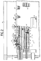
- FIG. 1 there are further vacuum chambers 1 ', 1' 'to the side of the rectangular vacuum chamber 1, which are connected to one another in a line via locks (not shown in detail) in the process chamber walls 2, 3.
- the anodes 4, 5 are arranged parallel to one another and transversely to the substrate transport direction and to the direction of extension of the chambers 1, 1 'and 1' 'in such a way that the rectangular hollow profiles 6, 7 and the screens 8, 9 are aligned with the center of the chamber , wherein the channels for the coolant inlet 6a, 7a and return 6b, 7b are arranged in the hollow profiles, in which in turn the gas distributor pipes 6f, 7f are centrally attached. Furthermore, the channels for process gas 6d, 7d, ... on the underside with openings 6e, 6e ', ... which repeat at certain intervals; 7e, 7e ', ... for the exit of the process gas from the channels 6d, 7d into the vacuum chamber 1.
- the substrate 10 can be moved below the anodes 4, 5 on the horizontally extending substrate plane 11 and in the direction of movement A through the vacuum chambers 1, 1 ', 1' ',...
- the cathode 12 with its flat target 35 is located above and between the screens 8, 9 and extends parallel to the hollow profiles 6, 7 and thus transversely to the direction of movement A of the substrate.
- the two Z-shaped sealing / guide plates 13, 14 are arranged such that they close the gaps remaining between the hollow profiles 6, 7 and the process chamber walls 2, 3 of the vacuum chamber 1 together with the sealing tubes 30, 31 made of elastic material.
- the hollow profiles 6, 7 are electrically insulated via insulating plates 15, 15 'and firmly connected to the process chamber walls 2, 3 by means of the screws 16, 17 and spacer plates 20, 20', for which purpose the screws 16, 17 in turn are enclosed by insulating bushes 18, 19 are.
- the anodes 4, 5 are shaped as L-profiles and each lie with their short legs 4a, 5a on the upper surfaces of the hollow profiles 6, 7, where they are anchored in the hollow profiles 6, 7 with bolts 21, 21 ', ... locked and clamped with wing screws 32, 32 ', ...
- the wing screws 32, 32 ', ... which are easily accessible through the upper opening 28 which can be closed by a cover 23, are held for this purpose by strips 24, 24', which in turn - as can be seen clearly in FIG. 2 - via spacer bushings 25 , 25 ', ... are screwed to the hollow profiles 6 and 7, respectively.
- each Panel 26, 27 each consists of a bottom part 26 ', 27', an end wall part 26 '', 27 '', a side wall part 26 ''',27''' and a collar part 26 x , 27 x .
- each hollow profile 6, 7 extending strip 24, 24 'each has a plurality of threaded bores for wing nuts 32, 32', ..., the threaded bolts of which rest on the bent legs 4a and 5a of the anodes 4, 5 and these immovably on the Hold hollow sections 6, 7.
- each hollow profile 6, 7 there is in each case an aperture 8 or 9, which essentially consists of a first leg 8 'or 9' extending parallel to the cathode 12 or its target surface 35 and an angle thereof extending from this hook-like second leg 8 ′′ or 9 ′′, which extends approximately 45 ° upwards.
- first leg 8 'or 9' with its end facing away from the cathode 12 bears against the process chamber wall 2 or 3 or against a hollow profile 38 or 39 which extends parallel to the hollow profile 6 or 7, the upper end of the second leg 8 ′′ or 9 ′′ with a nose-shaped extension 37, 37 ′ the top of the hollow profile 38 or 39 or its finger-like perpendicular extension 40 or 40 ′, the hollow profile 38, 39 with the process chamber wall 2, 3 is screwed and is sealed with the aid of a sealing hose 41, 42 against the process chamber wall.
- the lance or the gas distributor pipe 6f or 7f is distributed over its length, and is longitudinally displaceable on the pipe Locking disks 43, 43 ', ..., which can be fastened with the aid of clamping pieces 44, 44', ... to precisely definable sections of the gas distributor pipe 6f or 7f, so that the parts or sections 6d, 6d separated from the locking disks ', ... or 7d, 7d', ... can be supplied individually with gas, which enables the individual nozzles 6e, 6e ', ... or 7e, 7e', ... with different gas flows to supply.
- the anodes are covered comparatively quickly with an insulating layer during the sputtering process, which considerably limits their service life.
- the coated anodes must then be regularly removed from the process chamber and removed from the insulating layer, for example by sandblasting, which means a significant time delay in the production process.
- the anodes 4, 5 according to the invention can be made of steel, which increases their service life. They can be removed particularly easily after loosening the wing screws 32, 32 ', ... through the opening 28 from the chamber 1, 1', ..., which leads to a reduction in the maintenance time of the system.
Abstract
Description
Die Erfindung betrifft eine Vorrichtung zum Aufbringen dünner Schichten auf ein Substrat mittels des Kathodenzerstäubungsverfahrens in einer Vakuumkammer, durch die das zu beschichtende Substrat hindurchbewegbar ist und mit einer zwischen einer zu zerstäubenden Kathode und einer Anode angeordneten Blende, wobei die Substratebene unterhalb der Anode verläuft und wobei von der Wand der Vakuumkammer gehaltene, mit Kanälen versehene Hohlprofile - parallel zur Kathodenebene und im Bereich zwischen der Kathode und der Anode - vorgesehen sind, die von einem Kühlmedium und von einem Prozeßgas durchströmt sind, wobei die Kanäle für das Prozeßgas Öffnungen aufweisen, die quer zur Längsachse dieses Kanals verlaufen und den Austritt von Prozeßgas in die Vakuumkammer ermöglichen.The invention relates to a device for applying thin layers to a substrate by means of the sputtering method in a vacuum chamber, through which the substrate to be coated can be moved and with a screen arranged between a cathode to be sputtered and an anode, the substrate plane running below the anode, and wherein from the wall of the vacuum chamber, provided with channels, hollow profiles - parallel to the cathode plane and in the area between the cathode and the anode - are provided, which are flowed through by a cooling medium and by a process gas, the channels for the process gas having openings which are transverse run to the longitudinal axis of this channel and allow process gas to escape into the vacuum chamber.
Es ist eine Vorrichtung zum Aufbringen dünner Schichten auf ein Substrat mittels des Kathodenzerstäubungsverfahrens bekannt (EP 0 205 028). Hierbei ist zwischen der zu zerstäubenden Kathode und der Anode eine mechanische Blende vorgesehen, welche den Raum zwischen der Kathode und dem zu beschichtenden Substrat unterteilt. Diese Vorrichtung ist mit mehreren separaten Kühlrohren und Gasleitungsrohren für die Versorgung mit Temperiermedium und Prozeßgas versehen.A device for applying thin layers to a substrate by means of the cathode sputtering method is known (EP 0 205 028). A mechanical screen is provided between the cathode to be atomized and the anode, which divides the space between the cathode and the substrate to be coated. This device is provided with several separate cooling tubes and gas line tubes for the supply of temperature control medium and process gas.
Diese bekannte Vorrichtung hat den Nachteil, daß die Zu- und Rückführung des Temperiermediums sowie die Versorgung mit Prozeßgas jeweils über separate, mehrstückige Rohrleitungen erfolgt und somit sehr anfällig für Betriebsstörungen und aufwendig in der Herstellung und Wartung ist. Die Rohrleitungen weisen nämlich Biegungen, Wicklungen, Schraubverbindungen und Lötstellen auf, die sich unter Betriebsbedingungen der Vorrichtung im Vakuum befinden, was durch zusätzlichen Einfluß von prozeßbedingter Wärme zu Haarrissen und Undichtigkeiten in den Rohrleitungen führt. Diese Undichtigkeiten (Lecks) beeinträchtigen zunächst die Schichtqualität, beispielsweise die Haftfähigkeit, der auf das Substrat aufzubringenden Schicht beim Zerstäubungsprozeß (Sputtern) und führen anschließend und zwangsläufig zum Total-Ausfall der Gesamtanlage, der immer mit erheblichem Aufwand und immensen Kosten verbunden ist.This known device has the disadvantage that the supply and return of the temperature control medium and the supply of process gas each take place via separate, multi-piece pipelines and are therefore very susceptible to malfunctions and expensive to manufacture and maintain. The pipes have bends, windings, screw connections and solder joints that are in a vacuum under the operating conditions of the device, which leads to hairline cracks and leaks in the pipes due to the additional influence of process-related heat. These leaks (leaks) initially impair the layer quality, for example the adhesiveness of the layer to be applied to the substrate during the sputtering process (sputtering) and subsequently and inevitably lead to total failure of the entire system, which is always associated with considerable effort and immense costs.
Um die Betriebssicherheit spürbar zu erhöhen und damit die Ausfallzeiten zu reduzieren, die Herstellung und Wartung deutlich zu vereinfachen und damit eine wesentliche Reduzierung der Herstell- und Betriebskosten zu erreichen, hat man auch vorgeschlagen (DE 40 06 511 A1), sowohl das Temperiermedium als auch das Prozeßgas in Kanälen zu führen, die von einem einstückig und als Hohlprofil ausgeformten Bauteil gebildet sind, wobei Öffnungen für den Austritt des Gases quer zur Längsachse der Kanäle verlaufen, wobei die Anoden und Blenden unmittelbar mit dem Hohlprofil verschraubt sind.In order to noticeably increase operational safety and thus reduce downtimes, manufacturing and to simplify maintenance significantly and thus to achieve a significant reduction in manufacturing and operating costs, it has also been proposed (
Der vorliegenden Erfindung liegt nun die Aufgabe zugrunde, die bekannte Vorrichtung so zu verbessern, daß das Auswechseln der Anoden und Blenden leicht von der Oberseite der Prozeßkammer aus ohne Zuhilfenahme von Werkzeugen und ohne Blickkontakt erfolgen kann. Darüber hinaus sollen die Standzeit der Anoden und die thermische Belastbarkeit der Blenden verbessert werden.The present invention has for its object to improve the known device so that the replacement of the anodes and screens can be easily done from the top of the process chamber without the use of tools and without eye contact. In addition, the service life of the anodes and the thermal resistance of the screens are to be improved.
Gemäß der vorliegenden Erfindung wird diese Aufgabe gelöst durch als Profilschienen mit L-förmigem Querschnitt ausgebildete Anoden, deren kurze Schenkel jeweils die Hohlprofile übergreifend auf den Oberseiten der Hohlprofile abgestützt sind und in dieser Lage von Bolzen gehalten sind, die sich von den Oberseiten aus nach oben zu erstrecken und mit Bohrungen in den kurzen Schenkeln korrespondieren.
Vorzugsweise weist jede etwa plattenförmige Blende an ihrem der Prozeßkammerwand zugewandten Abschnitt zwei Schenkel auf, von denen der eine Schenkel mit seiner Stirnfläche an der Prozeßkammerwand abgestützt ist und der andere Schenkel etwa hakenförmig ausgebildet ist und mit seinem freien Ende oder einer an diesem Ende angeordneten Nase eine an der Prozeßkammerwand befestigte Leiste oder ein Hohlprofil übergreift.According to the present invention, this object is achieved by anodes designed as profile rails with an L-shaped cross section, the short legs of which are each supported overlapping the hollow profiles on the top sides of the hollow profiles and are held in this position by bolts which extend upwards from the top sides to extend and correspond to holes in the short legs.
Each approximately plate-shaped diaphragm preferably has two legs on its section facing the process chamber wall, one of which legs Leg is supported with its end face on the process chamber wall and the other leg is approximately hook-shaped and with its free end or a nose arranged at this end engages over a strip attached to the process chamber wall or a hollow profile.
Weitere Einzelheiten und Merkmale sind in den Patentansprüchen näher beschrieben und gekennzeichnet.Further details and features are described and characterized in more detail in the claims.
Die Erfindung läßt die verschiedensten Ausführungsmöglichkeiten zu; eine davon ist in den anhängenden Zeichnungen schematisch näher dargestellt, und zwar zeigen:
Figur 1- den Schnitt quer durch eine Kathodenstation mit an beiden Prozeßkammerwänden aufgebrachten Hohlprofilen und mit an den Hohlprofilen angehängten bzw. angeschraubten L-förmigen Anoden und mehrschenkligen Blenden,
Figur 2- die Seitenansicht eines Teils eines Hohlprofils gemäß
Figur 1, teilweise im Längsschnitt und - Figur 3
- die Draufsicht auf ein Stirnblenden-Paar gemäß der Kathodenstation nach
Figur 1.
- Figure 1
- the cross-section through a cathode station with hollow profiles applied to both process chamber walls and with L-shaped anodes attached or screwed to the hollow profiles and multi-leg panels,
- Figure 2
- the side view of part of a hollow profile according to Figure 1, partially in longitudinal section and
- Figure 3
- the top view of a pair of faceplates according to the cathode station of Figure 1.
Wie Figur 1 zeigt, schließen sich seitlich der rechteckigen Vakuumkammer 1 noch weitere Vakuumkammern 1', 1'' an, die über Schleusen (nicht näher dargestellt) in den Prozeßkammerwänden 2, 3 in einer Linie miteinander verbunden sind.As shown in FIG. 1, there are further vacuum chambers 1 ', 1' 'to the side of the
In der Vakuumkammer 1 sind die Anoden 4, 5 parallel zueinander und quer zur Substrattransportrichtung und zur Erstreckungsrichtung der Kammern 1, 1' und 1'' so angeordnet, daß die rechteckigen Hohlprofile 6, 7 sowie die Blenden 8, 9 zur Kammermitte hin ausgerichtet sind, wobei die Kanäle für den Kühlmittelzulauf 6a, 7a und -rücklauf 6b, 7b in den Hohlprofilen angeordnet sind, in denen wiederum die Gasverteilerrohre 6f, 7f zentrisch befestigt sind. Weiterhin sind die Kanäle für Prozeßgas 6d, 7d, ... auf der Unterseite mit sich in bestimmten Abständen wiederholenden Öffnungen 6e, 6e', ...; 7e, 7e', ... für den Austritt des Prozeßgases aus den Kanälen 6d, 7d in die Vakuumkammer 1 versehen. Das Substrat 10 ist unterhalb der Anoden 4, 5 auf der sich horizontal erstreckenden Substratebene 11 und in der Bewegungsrichtung A durch die Vakuumkamner 1, 1', 1'', ...hindurch bewegbar.In the
Die Kathode 12 mit ihrem planen Target 35 befindet sich oberhalb und zwischen den Blenden 8, 9 und erstreckt sich parallel zu den Hohlprofilen 6, 7 und somit quer zur Bewegungsrichtung A des Substrats.The
Die beiden Z-förmigen Dicht-/Leitbleche 13, 14 sind so angeordnet, daß sie die zwischen den Hohlprofilen 6, 7 und den Prozeßkammerwänden 2, 3 der Vakuumkammer 1 verbleibenden Spalte zusammen mit den Dichtschläuchen 30, 31 aus elastischem Werkstoff verschließen.The two Z-shaped sealing /
Die Hohlprofile 6, 7 sind über Isolierplatten 15, 15' elektrisch isoliert und mit Hilfe der Schrauben 16, 17 und Distanzplatten 20, 20' mit den Prozeßkammerwänden 2, 3 fest verbunden, wozu die Schrauben 16, 17 ihrerseits von Isolierbuchsen 18, 19 umschlossen sind. Die Anoden 4, 5 sind als L-Profile ausgeformt und liegen jeweils mit ihren kurzen Schenkeln 4a, 5a auf den oberen Flächen der Hohlprofile 6, 7 auf, wo sie mit Hilfe von in den Hohlprofilen 6, 7 verankerten Bolzen 21, 21', ... arretiert und mit Flügelschrauben 32, 32', ... festgeklemmt sind. Die Flügelschrauben 32, 32', ... , die durch die obere von einem Deckel 23 verschließbare Öffnung 28 gut zugänglich sind, werden dazu von Leisten 24, 24' gehalten, die ihrerseits - wie in Figur 2 gut ersichtlich ist - über Abstandsbuchsen 25, 25', ... mit den Hohlprofilen 6 bzw. 7 verschraubt sind. Die beiden Stirnwände 29, 29' jeder Prozeßkammer 1, 1', 1'', ... sind jeweils mit Hilfe von aus Blechzuschnitten geformten Blendenpaaren 26, 27 abgeschirmt, die ebenfalls auf der Oberseite der Rechteckprofile 6, 7 gehalten sind, wobei jede Blende 26, 27 jeweils aus einem Bodenteil 26', 27', einem Stirnwandteil 26'', 27'', einem Seitenwandteil 26 ''', 27''' und einem Kragenteil 26x, 27x besteht. Die sich jeweils oberhalb jedes Hohlprofils 6, 7 erstreckende Leiste 24, 24' weist jeweils eine Vielzahl von Gewindebohrungen für Flügelmuttern 32, 32', ... auf, deren Gewindebolzen auf den abgebogenen Schenkeln 4a bzw. 5a der Anoden 4, 5 aufliegen und diese unverrückbar auf den Hohlprofilen 6, 7 halten. Die Leisten 24, 24' ihrerseits sind mit Hilfe einer Reihe von Schrauben 33, 33', ... mit Abstandshülsen 25, 25', ... mit den Hohlprofilen 6 bzw. 7 verschraubt. Unterhalb jedes Hohlprofils 6, 7 ist jeweils eine Blende 8 bzw. 9 angeordnet, die im Wesentlichen aus einem sich parallel zur Kathode 12 bzw. dessen Targetfläche 35 erstreckenden ersten Schenkel 8' bzw. 9' und einem sich von diesem aus unter einem Winkel von etwa 45° nach oben zu erstreckenden hakenartigen zweiten Schenkel 8'' bzw. 9'' gebildet ist. Während der erste Schenkel 8' bzw. 9' mit seinem der Kathode 12 abgewandten Ende an der Prozeßkammerwand 2 bzw. 3 bzw. an einem sich parallel zum Hohlprofil 6 bzw. 7 erstreckenden Hohlprofil 38 bzw. 39 anliegt, übergreift jeweils das obere Ende des zweiten Schenkels 8'' bzw. 9'' mit einem nasenförmigen Ansatz 37, 37' die Oberseite des Hohlprofils 38 bzw. 39 bzw. dessen fingerartigen lotrecht stehenden Ansatz 40 bzw. 40', wobei das Hohlprofil 38, 39 mit der Prozeßkammerwand 2, 3 verschraubt ist und mit Hilfe eines Dichtschlauchs 41, 42 gegenüber der Prozeßkammerwand abgedichtet ist.The
Wie Figur 2 zeigt, weist die Lanze bzw. das Gasverteilerrohr 6f bzw. 7f auf seiner Länge verteilt angeordnet, auf dem Rohr längsverschiebliche Sperrscheiben 43, 43', ... auf, die mit Hilfe von Klemmstücken 44, 44', ... an genau bestimmbaren Abschnitten des Gasverteilerrohres 6f bzw. 7f befestigbar sind, so daß die von den Sperrscheiben abgetrennten Partien oder Abschnitte 6d, 6d', ... bzw. 7d, 7d', ... einzeln mit Gas versorgt werden können, was es ermöglicht, die einzelnen Düsen 6e, 6e', ... bzw. 7e, 7e', ... mit unterschiedlichen Gasströmen zu versorgen. Die Kombination von Gasverteilerrohr, Sperrscheiben und Hohlprofil gestattet es also, die aus den Düsen 6e, 6e', ... bzw. 7e, 7e', ... austretenden Gasströme den Prozeßparametern anzugleichen, was eine besonders gleichmäßige Schichtverteilung auf dem Substrat 10 ermöglicht.As FIG. 2 shows, the lance or the
Bei bekannten Vorrichtungen des beschriebenen Typs werden die Anoden während des Sputtervorgangs vergleichsweise schnell mit einer isolierenden Schicht überzogen, was deren Standzeit wesentlich einschränkt. Die beschichteten Anoden müssen dann regelmäßig aus der Prozeßkammer ausgebaut und z.B. durch Sandstrahlen von der isolierenden Schicht befreit werden, was eine wesentliche Zeitverzögerung im Produktionsprozeß bedeutet. Die erfindungsgemäßen Anoden 4, 5 können aus Stahl hergstellt sein, was ihre Standzeit erhöht. Sie lassen sich besonders leicht nach dem Lösen der Flügelschrauben 32, 32', ... durch die Öffnung 28 aus der Kammer 1, 1', ... entfernen, was zu einer Verkürzung der Wartungszeit der Anlage führt. Bekannte Anoden sind mit Hilfe von Isolierbuchsen und Teflonstreifen an den Wänden der Prozeßkammer befestigt, die bis in den Bereich der Sputterzone hineinragen, was nach einer bestimmten Sputterzeit zu Funktionsproblemen führt, da diese Teile ungekühlt sind, mit der Folge, daß die bekannten Anoden thermisch nur gering belastbar sind.In known devices of the type described, the anodes are covered comparatively quickly with an insulating layer during the sputtering process, which considerably limits their service life. The coated anodes must then be regularly removed from the process chamber and removed from the insulating layer, for example by sandblasting, which means a significant time delay in the production process. The
- 1, 1', 1''1, 1 ', 1' '
- VakuumkammerVacuum chamber
- 22nd
- ProzeßkammerwandProcess chamber wall
- 33rd
- ProzeßkammerwandProcess chamber wall
- 4, 4a4, 4a
- Anodeanode
- 5, 5a5, 5a
- Anodeanode
- 66
- HohlprofilHollow profile
- 6a6a
- Kanal für KühlmittelzulaufCoolant inlet channel
- 6b6b
- Kanal für KühlmittelrücklaufCoolant return channel
- 6c6c
- Verbindungskanal für KühlmittelConnection channel for coolant
- 6d6d
- Kanal für ProzeßgasProcess gas channel
- 6e, 6e', ...6e, 6e ', ...
- Öffnungopening
- 6f6f
- GasverteilerrohrGas distribution pipe
- 6g6g
- ReduzierstückReducer
- 6h6h
- ReduzierstückReducer
- 6i6i
- DichtringSealing ring
- 6k6k
- Öffnungopening
- 6l6l
- DichtringSealing ring
- 77
- HohlprofilHollow profile
- 7a7a
- Kanal für KühlmittelzulaufCoolant inlet channel
- 7b7b
- Kanal für KühlmittelrücklaufCoolant return channel
- 7c7c
- Verbindungskanal für KühlmittelConnection channel for coolant
- 7d7d
- Kanal für ProzeßgasProcess gas channel
- 7e, 7e', ...7e, 7e ', ...
- Öffnungopening
- 7f7f
- GasverteilerGas distributor
- 7k7k
- Öffnungopening
- 8, 8', 8''8, 8 ', 8' '
- Blendecover
- 9, 9', 9''9, 9 ', 9' '
- Blendecover
- 1010th
- SubstratSubstrate
- 1111
- SubstratebeneSubstrate level
- 1212th
- Kathodecathode
- 1313
- Dicht-/LeitblechSealing / baffle
- 1414
- Dicht-/LeitblechSealing / baffle
- 15, 15'15, 15 '
- IsolierplatteInsulating plate
- 1616
- Schraubescrew
- 1717th
- Schraubescrew
- 1818th
- IsolierbuchseInsulating bush
- 1919th
- IsolierbuchseInsulating bush
- 20, 20'20, 20 '
- DistanzplatteSpacer plate
- 21, 21'21, 21 '
- Bolzenbolt
- 22, 22'22, 22 '
- FlügelschraubeWing screw
- 2323
- Deckelcover
- 24, 24'24, 24 '
- Leistestrip
- 25, 25'25, 25 '
- AbstandsbuchsenSpacer bushings
- 26, 26',...26x 26, 26 ', ... 26 x
- Blendecover
- 27, 27',...27x 27, 27 ', ... 27 x
- Blendecover
- 2828
- Öffnungopening
- 2929
- StirnwandFront wall
- 3030th
- DichtschlauchSealing hose
- 3131
- DichtschlauchSealing hose
- 32, 32', ...32, 32 ', ...
- FlügelschraubeWing screw
- 33, 33', ...33, 33 ', ...
- Schraubescrew
- 3535
- TargetTarget
- 36, 36',...36, 36 ', ...
- SacklochbohrungBlind hole
- 37, 37'37, 37 '
- Nasenose
- 3838
- HohlprofilHollow profile
- 3939
- HohlprofilHollow profile
- 40, 40'40, 40 '
- Ansatz, NaseNeck, nose
- 4141
- DichtschlauchSealing hose
- 4242
- DichtschlauchSealing hose
- 43, 43', ...43, 43 ', ...
- SperrscheibeLock washer
- 44, 44', ...44, 44 ', ...
- KlemmstückClamp
- AA
- Bewegungsrichtung des SubstratsDirection of movement of the substrate
Claims (7)
Priority Applications (1)
| Application Number | Priority Date | Filing Date | Title |
|---|---|---|---|
| EP99112252A EP0957507A1 (en) | 1995-04-11 | 1996-01-24 | Apparatus for depositing thin layers on a substrate |
Applications Claiming Priority (2)
| Application Number | Priority Date | Filing Date | Title |
|---|---|---|---|
| DE19513691A DE19513691A1 (en) | 1995-04-11 | 1995-04-11 | Device for applying thin layers on a substrate |
| DE19513691 | 1995-04-11 |
Related Child Applications (1)
| Application Number | Title | Priority Date | Filing Date |
|---|---|---|---|
| EP99112252A Division EP0957507A1 (en) | 1995-04-11 | 1996-01-24 | Apparatus for depositing thin layers on a substrate |
Publications (2)
| Publication Number | Publication Date |
|---|---|
| EP0737998A2 true EP0737998A2 (en) | 1996-10-16 |
| EP0737998A3 EP0737998A3 (en) | 1998-05-13 |
Family
ID=7759457
Family Applications (2)
| Application Number | Title | Priority Date | Filing Date |
|---|---|---|---|
| EP99112252A Withdrawn EP0957507A1 (en) | 1995-04-11 | 1996-01-24 | Apparatus for depositing thin layers on a substrate |
| EP96100953A Withdrawn EP0737998A3 (en) | 1995-04-11 | 1996-01-24 | Device for depositing thin layers on a substrate |
Family Applications Before (1)
| Application Number | Title | Priority Date | Filing Date |
|---|---|---|---|
| EP99112252A Withdrawn EP0957507A1 (en) | 1995-04-11 | 1996-01-24 | Apparatus for depositing thin layers on a substrate |
Country Status (9)
| Country | Link |
|---|---|
| US (1) | US5662784A (en) |
| EP (2) | EP0957507A1 (en) |
| JP (1) | JPH08291383A (en) |
| KR (1) | KR100230072B1 (en) |
| CN (1) | CN1068639C (en) |
| BR (1) | BR9601309A (en) |
| CA (1) | CA2173891A1 (en) |
| DE (2) | DE19513691A1 (en) |
| TW (1) | TW402166U (en) |
Cited By (1)
| Publication number | Priority date | Publication date | Assignee | Title |
|---|---|---|---|---|
| EP0872573A1 (en) * | 1997-04-12 | 1998-10-21 | Leybold Systems GmbH | Vacuum processing apparatus for depositing thin layers |
Families Citing this family (20)
| Publication number | Priority date | Publication date | Assignee | Title |
|---|---|---|---|---|
| DE19734079A1 (en) * | 1997-08-07 | 1999-02-11 | Leybold Systems Gmbh | Cathode for a unit for target sputtering |
| DE19741708A1 (en) * | 1997-09-22 | 1999-04-01 | Leybold Systems Gmbh | Apparatus for coating a substrate with thin layers |
| DE29717418U1 (en) * | 1997-09-26 | 1998-01-22 | Leybold Systems Gmbh | Device for applying thin layers on a substrate |
| DE19755837A1 (en) * | 1997-12-16 | 1999-06-17 | Leybold Ag | Sputtering unit employs an electrically isolated substrate edge mask |
| US6943066B2 (en) * | 2002-06-05 | 2005-09-13 | Advantech Global, Ltd | Active matrix backplane for controlling controlled elements and method of manufacture thereof |
| US7166199B2 (en) * | 2002-12-18 | 2007-01-23 | Cardinal Cg Company | Magnetron sputtering systems including anodic gas distribution systems |
| US7879209B2 (en) * | 2004-08-20 | 2011-02-01 | Jds Uniphase Corporation | Cathode for sputter coating |
| US8500973B2 (en) * | 2004-08-20 | 2013-08-06 | Jds Uniphase Corporation | Anode for sputter coating |
| US20080308417A1 (en) * | 2005-03-14 | 2008-12-18 | Toyoaki Hirata | Sputtering Apparatus |
| KR101174146B1 (en) * | 2005-06-28 | 2012-08-14 | 엘지디스플레이 주식회사 | sputtering apparatus |
| US7850828B2 (en) * | 2006-09-15 | 2010-12-14 | Cardinal Cg Company | Enhanced virtual anode |
| US8557093B2 (en) * | 2007-03-22 | 2013-10-15 | Sunpower Corporation | Deposition system with electrically isolated pallet and anode assemblies |
| EP2103709A1 (en) * | 2008-02-28 | 2009-09-23 | Applied Materials, Inc. | Backside coating prevention device and method. |
| EP2096192A1 (en) * | 2008-02-28 | 2009-09-02 | Applied Materials, Inc. | Backside coating prevention device. |
| CN102002675B (en) * | 2009-08-28 | 2013-07-03 | 鸿富锦精密工业(深圳)有限公司 | Gas intake device of vacuum sputtering equipment |
| CN102623656A (en) * | 2012-04-06 | 2012-08-01 | 西北工业大学 | Fixer for underwater vehicle battery pack |
| CN103898462B (en) * | 2012-12-29 | 2017-08-22 | 深圳富泰宏精密工业有限公司 | Magnetic control sputtering film plating device |
| DE102013204132B4 (en) * | 2013-03-11 | 2015-04-02 | Von Ardenne Gmbh | Anode support device for magnetron sputtering |
| JP6189122B2 (en) * | 2013-07-19 | 2017-08-30 | 日東電工株式会社 | Sputtering equipment |
| EP3254296B1 (en) | 2015-02-03 | 2021-04-14 | Cardinal CG Company | Sputtering apparatus including gas distribution system |
Citations (2)
| Publication number | Priority date | Publication date | Assignee | Title |
|---|---|---|---|---|
| EP0205028A1 (en) * | 1985-06-12 | 1986-12-17 | Leybold Aktiengesellschaft | Apparatus for depositing thin layers on a substrate |
| EP0444253A2 (en) * | 1990-03-01 | 1991-09-04 | Leybold Aktiengesellschaft | Apparatus for the deposition of thin layers on a substrate |
Family Cites Families (5)
| Publication number | Priority date | Publication date | Assignee | Title |
|---|---|---|---|---|
| DE2522227A1 (en) * | 1975-05-20 | 1976-12-02 | Telic Corp | Sputtering material onto a target - using low gas pressure |
| US4407708A (en) * | 1981-08-06 | 1983-10-04 | Eaton Corporation | Method for operating a magnetron sputtering apparatus |
| US4425218A (en) * | 1982-03-30 | 1984-01-10 | Shatterproof Glass Corporation | Gas distribution system for sputtering cathodes |
| DE3800449A1 (en) * | 1988-01-09 | 1989-07-20 | Leybold Ag | METHOD AND DEVICE FOR PRODUCING MAGNETO-OPTICAL, STORAGE AND ERASABLE DATA CARRIERS |
| US4849087A (en) * | 1988-02-11 | 1989-07-18 | Southwall Technologies | Apparatus for obtaining transverse uniformity during thin film deposition on extended substrate |
-
1995
- 1995-04-11 DE DE19513691A patent/DE19513691A1/en not_active Withdrawn
- 1995-04-25 DE DE19515088A patent/DE19515088A1/en not_active Withdrawn
-
1996
- 1996-01-24 EP EP99112252A patent/EP0957507A1/en not_active Withdrawn
- 1996-01-24 EP EP96100953A patent/EP0737998A3/en not_active Withdrawn
- 1996-02-10 TW TW088201776U patent/TW402166U/en not_active IP Right Cessation
- 1996-03-25 US US08/622,443 patent/US5662784A/en not_active Expired - Fee Related
- 1996-04-04 KR KR1019960010160A patent/KR100230072B1/en not_active IP Right Cessation
- 1996-04-10 BR BR9601309A patent/BR9601309A/en not_active IP Right Cessation
- 1996-04-10 JP JP8088587A patent/JPH08291383A/en active Pending
- 1996-04-11 CA CA002173891A patent/CA2173891A1/en not_active Abandoned
- 1996-04-11 CN CN96105547A patent/CN1068639C/en not_active Expired - Fee Related
Patent Citations (2)
| Publication number | Priority date | Publication date | Assignee | Title |
|---|---|---|---|---|
| EP0205028A1 (en) * | 1985-06-12 | 1986-12-17 | Leybold Aktiengesellschaft | Apparatus for depositing thin layers on a substrate |
| EP0444253A2 (en) * | 1990-03-01 | 1991-09-04 | Leybold Aktiengesellschaft | Apparatus for the deposition of thin layers on a substrate |
Cited By (1)
| Publication number | Priority date | Publication date | Assignee | Title |
|---|---|---|---|---|
| EP0872573A1 (en) * | 1997-04-12 | 1998-10-21 | Leybold Systems GmbH | Vacuum processing apparatus for depositing thin layers |
Also Published As
| Publication number | Publication date |
|---|---|
| CN1068639C (en) | 2001-07-18 |
| JPH08291383A (en) | 1996-11-05 |
| CA2173891A1 (en) | 1996-10-12 |
| KR960039050A (en) | 1996-11-21 |
| DE19515088A1 (en) | 1997-01-02 |
| TW402166U (en) | 2000-08-11 |
| CN1140206A (en) | 1997-01-15 |
| EP0957507A1 (en) | 1999-11-17 |
| US5662784A (en) | 1997-09-02 |
| BR9601309A (en) | 1998-01-13 |
| DE19513691A1 (en) | 1996-10-17 |
| EP0737998A3 (en) | 1998-05-13 |
| KR100230072B1 (en) | 1999-11-15 |
Similar Documents
| Publication | Publication Date | Title |
|---|---|---|
| EP0737998A2 (en) | Device for depositing thin layers on a substrate | |
| EP0444253B1 (en) | Apparatus for the deposition of thin layers on a substrate | |
| DE3229694A1 (en) | COOLER | |
| EP1420912B1 (en) | Device for cooling material by creating a fan jet | |
| EP0317706B1 (en) | Flue gas channel for treating a flue gas | |
| EP0811818A1 (en) | Grate plate and its fabrication process | |
| EP0942792B1 (en) | Device for cooling extruded profiles | |
| DE19733940C2 (en) | Device for coating plate-shaped substrates with thin layers by means of cathode sputtering | |
| DE3015282C2 (en) | Device for the partial electroplating of conductive or made conductive surfaces | |
| EP3251762B1 (en) | Lubricating device for applying a lubricant when rolling a product to be rolled | |
| DE2339552A1 (en) | METHOD AND DEVICE FOR COOLING WELDINGS | |
| DE19736318C2 (en) | Device for coating plate-shaped substrates with thin layers by means of cathode sputtering | |
| CH624793A5 (en) | ||
| EP3638821B1 (en) | Nozzle for a hot-dip coating system | |
| DE2840293A1 (en) | PLATE HEAT EXCHANGER | |
| EP3638822B1 (en) | Apparatus and method for separating gas atmospheres | |
| EP3129522B1 (en) | Gas distribution apparatus in a vacuum chamber, comprising a gas conducting device | |
| DE4337342A1 (en) | Device for cooling rolled strips | |
| EP1019946A2 (en) | Device for coating panel-shaped substrates | |
| EP3591088B1 (en) | Device for hot dip coating of a metal strip | |
| DE102006059848A1 (en) | Positioning plate for connecting two processing chambers is mounted horizontally on one edge between them and has central slot, allowing workpieces to be passed through it from one chamber to another | |
| DE102012000397B4 (en) | Device with a fastening means in a vacuum treatment plant | |
| DE19756162C2 (en) | Sputtering device | |
| DE102021124553A1 (en) | Gas supply structure and processing device | |
| DE19546114A1 (en) | Apparatus for producing thin, in particular, reactive metal layers on substrate |
Legal Events
| Date | Code | Title | Description |
|---|---|---|---|
| PUAI | Public reference made under article 153(3) epc to a published international application that has entered the european phase |
Free format text: ORIGINAL CODE: 0009012 |
|
| AK | Designated contracting states |
Kind code of ref document: A2 Designated state(s): AT BE DE ES FR GB IT LU NL SE |
|
| PUAL | Search report despatched |
Free format text: ORIGINAL CODE: 0009013 |
|
| AK | Designated contracting states |
Kind code of ref document: A3 Designated state(s): AT BE DE ES FR GB IT LU NL SE |
|
| 17P | Request for examination filed |
Effective date: 19980528 |
|
| 17Q | First examination report despatched |
Effective date: 19990305 |
|
| GRAG | Despatch of communication of intention to grant |
Free format text: ORIGINAL CODE: EPIDOS AGRA |
|
| GRAG | Despatch of communication of intention to grant |
Free format text: ORIGINAL CODE: EPIDOS AGRA |
|
| GRAH | Despatch of communication of intention to grant a patent |
Free format text: ORIGINAL CODE: EPIDOS IGRA |
|
| GRAG | Despatch of communication of intention to grant |
Free format text: ORIGINAL CODE: EPIDOS AGRA |
|
| GRAH | Despatch of communication of intention to grant a patent |
Free format text: ORIGINAL CODE: EPIDOS IGRA |
|
| RAP1 | Party data changed (applicant data changed or rights of an application transferred) |
Owner name: APPLIED FILMS GMBH & CO. KG |
|
| STAA | Information on the status of an ep patent application or granted ep patent |
Free format text: STATUS: THE APPLICATION IS DEEMED TO BE WITHDRAWN |
|
| 18D | Application deemed to be withdrawn |
Effective date: 20010731 |