EP0736740B1 - Ammunition positioning - Google Patents
Ammunition positioning Download PDFInfo
- Publication number
- EP0736740B1 EP0736740B1 EP19950118614 EP95118614A EP0736740B1 EP 0736740 B1 EP0736740 B1 EP 0736740B1 EP 19950118614 EP19950118614 EP 19950118614 EP 95118614 A EP95118614 A EP 95118614A EP 0736740 B1 EP0736740 B1 EP 0736740B1
- Authority
- EP
- European Patent Office
- Prior art keywords
- case
- cartridge
- ammunition
- guide surface
- holding groove
- Prior art date
- Legal status (The legal status is an assumption and is not a legal conclusion. Google has not performed a legal analysis and makes no representation as to the accuracy of the status listed.)
- Expired - Lifetime
Links
Images
Classifications
-
- F—MECHANICAL ENGINEERING; LIGHTING; HEATING; WEAPONS; BLASTING
- F41—WEAPONS
- F41A—FUNCTIONAL FEATURES OR DETAILS COMMON TO BOTH SMALLARMS AND ORDNANCE, e.g. CANNONS; MOUNTINGS FOR SMALLARMS OR ORDNANCE
- F41A9/00—Feeding or loading of ammunition; Magazines; Guiding means for the extracting of cartridges
- F41A9/54—Cartridge guides, stops or positioners, e.g. for cartridge extraction
- F41A9/55—Fixed or movable guiding means, mounted on, or near, the cartridge chamber
Definitions
- the invention relates to a device for supporting the supply of an ammunition cartridge to a firing point of a firearm and to lead away the cartridge case of the Ammunition cartridge from the ignition point according to the preamble of claim 1 such a device is well known.
- Specially designed are designed to feed ammunition cartridges into firearms Feeders used.
- Such feeders are for example rotatable drums with multiple openings for ammunition cartridges.
- the ammunition cartridges are from outside of the firearm body arranged magazines pushed in drums and conveyed to the firing position by rotating the drums. To the The ammunition rounds are fired using firing pins.
- the empty cartridge cases are blown up by the explosion pressure and over Guide devices, for example via ejection channels, from the ignition points led away.
- a first disadvantage of such feeders is that Explosive pressure elastic deformations of the firearm body and plastic deformations of the cartridge cases are generated. When easing of the explosion pressure, let the elastic deformation of the firearm body after, during the plastic deformations of the cartridge cases persist. When using a firearm with a drum feed this leads to parasitic frictional force moments between the deformed Cartridge cases and the firearm body. The speed of rotation the drum is slowed down, the bombardment rate is reduced, which is undesirable. Again, the higher the drum speed are, the more powerful the firearm is, the bigger are the frictional force moments that occur.
- Frictional force moments due to plastic deformation of the cartridge cases should be reduced or eliminated.
- the appearance of chips that occur in the Ignition of the ammunition cartridges occurs, and that in the area of the firing pin holes come and so by clogging these holes Avoid functioning of firearms should be avoided become.
- This task is to be carried out using known and proven means and manufacturing processes be solvable.
- the device is said to use standardized ammunition cartridges be operable. It should be of a simple, robust design. 0 Finally, it should be reliable, largely maintenance-free and have a long service life his.
- a device for feeding ammunition is known from DE-C-719 360 , which has a first guide surface, a second guide surface, an ignition point and a holding groove.
- this is a device for the two-sided supply of ammunition cartridges with a reciprocating movement, and not a device for supporting the supply of an ammunition cartridge to an ignition point and guiding the cartridge case of the ammunition cartridge away from the ignition point.
- the idea of the invention is to supply ammunition cartridges to support ignition points by a positioning device.
- Ammunition cartridges are via a first guide surface and by means of a holding groove sliding and holding guided and checked at the ignition point and precisely positioned.
- the geometry of the positioning device is in line with the geometry adapted from standard ammunition cartridges.
- Ammunition cartridges slide with their sleeve bottoms over an advantageously oblique to the weft direction arranged guide surface and are with their sleeve edges in the holding groove kept leading.
- the ignition screw groove is a recess for deformed ignition screws of the ammunition cartridges and Cartridge cases and allows the case bottoms to slide smoothly deformed ignition screws on the other guide surface.
- FIG. 1 is a top view
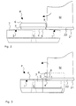
- Figure 2 is a front view
- Figure 3 is a side view.
- This Design of the positioning device P is advantageous but not mandatory.
- the person skilled in the art is aware of the present invention in this regard diverse possibilities of varying this embodiment Available.
- Such a positioning device P is particularly suitable for Use in automatic firearms as used in the Swiss Patent applications P0663CH and P0664CH are disclosed.
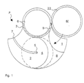
- FIG. 1 is a top view against the weft direction.
- the feed and The path of the ammunition cartridges is clockwise.
- the viewer looks into the opening 5 for the firing pin to fire the ammunition rounds M.
- FIG. 1 there are two guide surfaces 1, 2, one positioning surface 8 and a retaining groove 3 of the positioning device P merging into one another, worked in one piece in a base plate.
- the ammunition cartridges M are advantageously in the cartridge chambers kept stored by drums, fed by rotating the drums.
- Other feeding devices such as the use of a Feed levers are possible.
- Such feeding devices can be designed freely and not shown in the figures for reasons of clarity.
- Those skilled in the art are familiar with the present invention in a variety of ways Possibilities of using the positioning device according to the invention P available in conjunction with feeders.
- the position of feeding the ammunition cartridges M is analogous to analog clock dial, referred to as the feed point or position "3 o'clock".
- the sleeve edges 22 are compared to the cartridge diameters worked slightly protruding. These protruding sleeve edges 22 are clearly visible in the views according to FIGS. 2 and 3.
- the Protruding sleeve edges 22 are in the holding groove 3 of the positioning device P guided and partially held by this retaining groove 3.
- the retaining groove 3 is on one side of the guide surfaces 1, 2 out of the guide surfaces 1,2 protruding reinforcements 6 of a base plate of the positioning device P attached.
- it goes fluently without Heel, from the guide surface 1 in the positioning surface 8 and in the guide surface 2 over.
- the ends of the holding groove 3 are open, such that the ammunition cartridges M at the feed point in the "3 o'clock” position their sleeve edges 22 in and out of the holding groove 3 without tilt them about their axis of rotation.
- the ammunition cartridges M are advantageously inserted directly into the open ends of the retaining groove 3.
- the edges of these open ends of this retaining groove 3 are rounded, so that the protruding sleeve edges 22 without tilting into the holding groove 3 will be introduced.
- the ammunition cartridges M are with the case bottoms 21 on the first Guide surface 1 standing and with parts of the sleeve edges 22 in the holding groove 3 holding, an ignition point 4 slidably fed.
- This feeding takes place in a controlled manner, preferably simultaneously, i.e. the ammunition cartridges M are simultaneously when placed on the first guide surface 1 led into the retaining groove 3.
- the Ignition point 4 is shown in dashed lines in the plan view according to FIG. 1. This position is referred to as ignition point 4 or position "6 o'clock" designated.
- the ammunition cartridges M are at the ignition point 4 their sleeve bottoms 21 partially on the positioning surface 8.
- the firing pin is not shown. It is from the back of the positioning device P, operated through hole 5.
- the feeding and positioning of the ammunition cartridges M at the ignition point 4 takes place along a feed path of the ammunition cartridges M in one
- the plane is almost perpendicular to the firing direction (see the feed arrows clockwise in Figures 1 to 3).
- This quasi vertical feeding is used for Avoid the following, listed in order of importance, Problems when inserting ammunition cartridges M in front of an ignition point 4.
- the case bottoms 21 of the ammunition cartridges M can be caused by improper use Storage and transport may be deformed.
- the case bottoms 21 of the ammunition cartridges M become, especially when using a firearm with drum feed, fed with irregular cadence. This cadence increases in constant fire, for example, with the temperature increase of the firearm body on.
- the sleeve bottoms 21 of the ammunition cartridges M manufactured with manufacturing tolerances.
- this is achieved by aligning the first guide surface 1 Avoided almost perpendicular to the firing direction.
- the alignment of the guide surface 1 narrows the accessible space in the holding groove 3 along the Feed path of the ammunition rounds M.
- the sleeve edges 22 sit loosely, i.e. with play in the holding groove 3, which leads to the supply of the ammunition cartridges M. the first guide surface 1 facilitated.
- the ignition point 4 in a Position 6 o'clock
- the sleeve edges 22 are tight, i.e. without play in the Haltutut 3, which is a precise positioning of the ammunition cartridges M on the optimal position of the ignition device at the ignition point 4 allows.
- the first guide surface 1 is oblique, at a small angle in the direction aligned perpendicular to the weft direction, so that the retaining groove 3 in one position 3 o'clock is wider than in a 6 o'clock position.
- This positioning over an inclined guide surface 1 is very reproducible, what leads to a very high security of the firearm.
- the shape of the sleeve edges 22 and the corresponding shape of the holding groove 3 are coordinated with one another, for example, the edges of the sleeve edges 22 are rounded, such that the ammunition cartridges M without tilting the first guide surface 1 happen.
- a person skilled in the art will have a variety of knowledge of the invention Possibilities of realizing such inclined guide surfaces 1, such tapered retaining grooves 3 and sleeve edges 22 free.
- the empty cartridge cases are guided away via the second guide surface 2.
- the cartridge cases are held in the holding groove 3 and along a path on the second guide surface 2 standing up to right edge of the second guide surface 2 sliding to an exit point led away.
- This path of the cartridge cases is like feeding the ammunition cartridges M in a plane quasi perpendicular to the direction of fire.
- a second guide surface 2 aligned with the firing direction is a tilt-free one allows the empty cartridge cases to slide away.
- the second guide surface extends 2 the accessible space in the holding groove 3. It is slanted, i.e. in one small angle in the opposite direction to the weft direction.
- the Sleeve edges 22 sit at the ignition point 4 (in a position 6 o'clock) tight and at the exit point (in a position 9 o'clock) they sit with Game in the holding groove 3.
- the holding groove 3 ends in the area of the exit point, so that empty cartridge cases without tilting around their axis of rotation a guide point with its sleeve edges 22 from the holding groove 3 executable are. Any deformations of the empty cartridge cases are caused by corrected this guidance with play so that tilting is not possible.
- the Those skilled in the art are familiar with the invention in many ways Adjust this game by the size and inclination of the guide surface for different types and materials of ammunition cases used to disposal.
- the positioning surface 8 has boundaries to the two guide surfaces 1, 2 and is perpendicular aligned to the firing direction. These limitations are, for example arcuate, for example segments of a circle with the diameter of the cartridge cases, which facilitates the supply and removal of the ammunition cartridges M.
- On the ignition point 4 are the ammunition cartridges M to be fired their sleeve bottoms 21 only in the overlapping area according to Figure 1 dashed ignition point 4 with the arc limited positioning area 8.
- this ignition screw groove 7 also possibly with the ammunition cartridges M or some other way into the firearm body introduced small impurities such as dust or water away. There is thus a pressure-operated cleaning of the ignition point 4 performed.
- the expert applies Knowledge of the present invention a variety of different configurations can make such ignition screw grooves 7.
- the great advantage of the invention is its universal applicability.
- the ammunition rounds M are fed in and out Guide surfaces 1,2 sliding without additional lubricants, such as Oil, fat are necessary.
- additional lubricants are under extreme weather and environmental conditions (cold, sandy desert) potential Sources of danger for reliable operation of the firearm
- Positioning device P is known and proven means and Manufacturing process producible.
- the positioning device P is standardized Ammunition cartridges can be operated with or without belt links. she is preferably made of metal and of simple, robust design, so that it is reliable, largely maintenance-free and has a long service life.
Landscapes
- Engineering & Computer Science (AREA)
- General Engineering & Computer Science (AREA)
- Portable Nailing Machines And Staplers (AREA)
Description
Die Erfindung betrifft eine Vorrichtung zum Unterstützen der Zuführung einer Munitionspatronen
zu einer Zündungsstelle einer Feuerwaffe und zum Wegführen der Patronenhülse der
Munitionspatrone aus der Zündungsstelle nach dem Oberbegriff des Anspruchs 1. Eine
derartige Vorrichtung ist hinlänglich bekannt. The invention relates to a device for supporting the supply of an ammunition cartridge
to a firing point of a firearm and to lead away the cartridge case of the
Ammunition cartridge from the ignition point according to the preamble of
Zum Zuführen von Munitionspatronen in Feuerwaffen werden speziell konzipierte Zuführvorrichtungen eingesetzt. Solche Zuführvorrichtungen sind beispielsweise drehbare Trommeln mit mehreren Öffnungen für Munitionspatronen. In solchen Feuerwaffen werden die Munitionspatronen aus ausserhalb des Feuerwaffenkörpers angeordneten Magazinen in Trommeln geschoben und durch Drehen der Trommeln an die Schussposition gefördert. An den Zündungsstellen werden die Munitionspatronen mittels Schlagbolzen gezündet. Die leeren Patronenhülsen werden durch den Explosionsdruck und über Wegführvorrichtungen, beispielsweise über Auswurfkanäle, von den Zündungsstellen weggeführt. Specially designed are designed to feed ammunition cartridges into firearms Feeders used. Such feeders are for example rotatable drums with multiple openings for ammunition cartridges. In such firearms, the ammunition cartridges are from outside of the firearm body arranged magazines pushed in drums and conveyed to the firing position by rotating the drums. To the The ammunition rounds are fired using firing pins. The empty cartridge cases are blown up by the explosion pressure and over Guide devices, for example via ejection channels, from the ignition points led away.
Ein erster Nachteil solcher Zuführvorrichtungen besteht darin, dass durch den Explosionsdruck elastischen Deformationen des Feuerwaffenkörpers und plastische Deformationen der Patronenhülsen erzeugt werden. Beim Nachlassen des Explosionsdruckes, lassen die elastischen Deformationen des Feuerwaffenkörpers nach, während die plastischen Deformationen der Patronenhülsen weiterbestehen. Bei Verwendung einer Feuerwaffe mit Trommelzuführung führt dies zu parasitären Reibungskraftmomenten zwischen den deformierten Patronenhülsen und dem Feuerwaffenkörper. Die Drehgeschwindigkeit der Trommel wird dadurch gebremst, die Beschusskadenz wird erniedrigt, was unerwünscht ist. Auch hier gilt wieder, dass je höher die Trommeldrehgeschwindigkeiten sind, je kräftiger die Feuerwaffe ausgelegt ist, desto grösser sind die auftretenden Reibungskraftmomente.A first disadvantage of such feeders is that Explosive pressure elastic deformations of the firearm body and plastic deformations of the cartridge cases are generated. When easing of the explosion pressure, let the elastic deformation of the firearm body after, during the plastic deformations of the cartridge cases persist. When using a firearm with a drum feed this leads to parasitic frictional force moments between the deformed Cartridge cases and the firearm body. The speed of rotation the drum is slowed down, the bombardment rate is reduced, which is undesirable. Again, the higher the drum speed are, the more powerful the firearm is, the bigger are the frictional force moments that occur.
Ein weiterer Nachteil solcher Zuführvorrichtungen besteht darin, dass beim Zünden der Munitionspatronen abgescherte Späne entstehen, die in den Bereich der Schlagbolzenbohrungen gelangen und so durch Verstopfung dieser Bohrungen die Funktionstüchtigkeit der Feuerwaffen beeinträchtigen kann. Another disadvantage of such feeders is that the Ignition of the ammunition sheared shavings that occur in the area of the firing pin holes and so by clogging them Drilling can affect the functionality of firearms.
Es ist somit Aufgabe der vorliegenden Erfindung, die oben erwähnten Nachteile zu beheben und eine verbesserte Vorrichtung der eingangs genannten Art zu schaffen, um sowohl die Zuführung der Munitionspatrone zur Zündungsstelle vor der Schussabgabe wie auch die Wegführung der Patronenhülse der Munitionspatrone von der Zündungsstelle nach der Schussabgabe zu unterstützen. It is therefore an object of the present invention to remedy the disadvantages mentioned above and to provide an improved device of the type mentioned at the beginning to both the supply of the ammunition cartridge to the ignition point before firing the shot as well as the Route the cartridge case of the ammunition cartridge from the ignition point to the Support firing.
Reibungskraftmomente infolge plastischer Deformationen der Patronenhülsen sollen reduziert oder eliminiert werden. Das Auftreten von Spänen, die beim Zünden der Munitionspatronen entstehen, und die in den Bereich der Schlagbolzenbohrungen gelangen und so durch Verstopfung dieser Bohrungen die Funktionstüchtigkeit der Feuerwaffen beeinträchtigen können, soll vermieden werden. Diese Aufgabe soll mit bekannten und bewährten Mitteln und Herstellungsverfahren lösbar sein. Die Vorrichtung soll mit standardisierten Munitionspatronen betreibbar sein. Sie soll von einfacher, robuster Bauart sein. 0 Schliesslich soll sie zuverlässig, weitgehend wartungsfrei und von hoher Lebensdauer sein. Frictional force moments due to plastic deformation of the cartridge cases should be reduced or eliminated. The appearance of chips that occur in the Ignition of the ammunition cartridges occurs, and that in the area of the firing pin holes come and so by clogging these holes Avoid functioning of firearms should be avoided become. This task is to be carried out using known and proven means and manufacturing processes be solvable. The device is said to use standardized ammunition cartridges be operable. It should be of a simple, robust design. 0 Finally, it should be reliable, largely maintenance-free and have a long service life his.
Die genannte Aufgabe der Erfindung wird durch die Vorrichtung, wie sie durch die Patentansprüche definiert ist, gelöst.The stated object of the invention is achieved by the device as defined by the claims is defined, solved.
Zwar ist aus der DE-C-719 360 eine Vorrichtung zum Zuführen von Munition bekannt, welche eine erste Führungsfläche, eine zweite Führungsfläche, eine Zündstelle und eine Haltenut aufweist. Hierbei handelt es sich aber um eine Vorrichtung zur zweiseitigen Zuführung von Munitionspatronen mit hin- und hergehender Bewegung, und nicht um eine Vorrichtung zur Unterstützung der Zuführung einer Munitionspatrone zu einer Zündungsstelle und der Wegführung der Patronenhülse der Munitionspatrone von der Zündungsstelle. A device for feeding ammunition is known from DE-C-719 360 , which has a first guide surface, a second guide surface, an ignition point and a holding groove. However, this is a device for the two-sided supply of ammunition cartridges with a reciprocating movement, and not a device for supporting the supply of an ammunition cartridge to an ignition point and guiding the cartridge case of the ammunition cartridge away from the ignition point.
Die Idee der Erfindung besteht darin, das Zuführen von Munitionspatronen zu Zündungsstellen durch eine Positioniervorrichtung zu unterstützen. Munitionspatronen werden über eine erste Führungsfläche und mittels einer Haltenut gleitend und haltend geführt und an der Zündungsstelle kontrolliert und präzise positioniert. Die Geometrie der Positioniervorrichtung ist an die Geometrie von Standard-Munitionspatronen angepasst. Munitionspatronen gleiten mit ihren Hülsenböden über eine vorteilhafterweise schräg zur Schussrichtung angeordnete Führungsfläche und werden mit ihren Hülsenrändern in der Haltenut führend gehalten.The idea of the invention is to supply ammunition cartridges to support ignition points by a positioning device. Ammunition cartridges are via a first guide surface and by means of a holding groove sliding and holding guided and checked at the ignition point and precisely positioned. The geometry of the positioning device is in line with the geometry adapted from standard ammunition cartridges. Ammunition cartridges slide with their sleeve bottoms over an advantageously oblique to the weft direction arranged guide surface and are with their sleeve edges in the holding groove kept leading.
Auf eine ähnliche Weise werden nach dem Zünden der Munitionspatronen die leeren Patronenhülsen durch die Positioniervorrichtung unterstützt weggeführt. Leere Patronenhülsen werden über eine weitere Führungsfläche und mittels der Haltenut gleitend und haltend geführt von der Zündungsstelle weggeführt. Die Patronenhülsen gleiten mit ihren Hülsenböden über diese zweite vorteilhafterweise schräg zur Schussrichtung ausgerichtete Führungsfläche und werden mit ihren Hülsenrändern in der Haltenut führend gehalten, sodass parasitäre Reibungskraftmomente zwischen Feuerwaffenkörper und Patronenhülse vermieden werden.In a similar way, after firing the ammunition rounds the empty cartridge cases supported away by the positioning device. Empty cartridge cases are over another guide surface and sliding and holding guided by the ignition point by means of the holding groove led away. The cartridge cases slide with their case bases over them second guide surface advantageously oriented obliquely to the firing direction and are held in the holding groove with their sleeve edges, so that parasitic frictional force moments between firearm body and Cartridge case can be avoided.
Durch das Anbringen einer Zündschraubennut in der zweiten Führungsfläche wird das Entstehen abgescherter Späne beim Zünden und Wegführen leerer Patronenhülsen von der Zündungsstelle vermieden. Die Zündschraubennut ist eine Aussparung für deformierte Zündschrauben der Munitionspatronen und Patronenhülsen und erlaubt ein reibungsfreies Gleiten der Hülsenböden mit deformierten Zündschrauben auf der weiteren Führungsfläche.By making an ignition screw groove in the second guide surface the formation of shaved shavings becomes empty when ignited and carried away Avoided cartridge cases from the ignition point. The ignition screw groove is a recess for deformed ignition screws of the ammunition cartridges and Cartridge cases and allows the case bottoms to slide smoothly deformed ignition screws on the other guide surface.
Anhand der folgenden Figuren wird die Erfindung im Detail erläutert.
- Fig.1
- zeigt eine Draufsicht gegen Schussrichtung eines Teiles einer bevorzugten Ausführungsform einer Positioniervorrichtung.
- Fig.2
- zeigt eine Frontansicht eines Teiles einer bevorzugten Ausführungsform
der Positioniervorrichtung gemäss
Figur 1. - Fig.3
- zeigt eine Seitenansicht eines Teiles einer bevorzugten Ausführungsform
der Positioniervorrichtung gemäss den
Figuren 1 und 2.
- Fig. 1
- shows a plan view against the firing direction of a part of a preferred embodiment of a positioning device.
- Fig. 2
- shows a front view of part of a preferred embodiment of the positioning device according to FIG. 1.
- Fig. 3
- shows a side view of part of a preferred embodiment of the positioning device according to FIGS. 1 and 2.
Die Figuren 1 bis 3 zeigen Teile einer bevorzugten Ausführungsform einer Positioniervorrichtung P in verschiedenen Ansichten. Figur 1 ist eine Draufsicht, Figur 2 ist eine Frontansicht und Figur 3 ist eine Seitenansicht. Diese Ausgestaltung der Positioniervorrichtung P ist vorteilhaft aber nicht zwingend. Dem Fachmann stehen diesbezüglich bei Kenntnis der vorliegenden Erfindung vielfältige Möglichkeiten der Variation dieser Ausführungsform zur Verfügung. Eine solche Positioniervorrichtung P eignet sich insbesondere zur Verwendung in automatischen Feuerwaffen, wie sie in den schweizerischen Patentanmeldungen P0663CH und P0664CH offenbart sind.Figures 1 to 3 show parts of a preferred embodiment of a Positioning device P in different views. FIG. 1 is a top view, Figure 2 is a front view and Figure 3 is a side view. This Design of the positioning device P is advantageous but not mandatory. The person skilled in the art is aware of the present invention in this regard diverse possibilities of varying this embodiment Available. Such a positioning device P is particularly suitable for Use in automatic firearms as used in the Swiss Patent applications P0663CH and P0664CH are disclosed.
Figur 1 ist eine Draufsicht entgegen der Schussrichtung. Die Zuführ- und
Wegführbahn der Munitionspatronen erfolgt im Uhrzeigersinn. Der Betrachter
schaut in die Öffnung 5 für den Schlagbolzen zum Zünden der Munitionspatronen
M. Gemäss Figur 1 sind zwei Führungsflächen 1,2, eine Positionierfläche
8 und eine Haltenut 3 der Positioniervorrichtung P ineinander übergehend,
einstückig in einer Grundplatte gearbeitet. Die erste Führungsfläche 1
zum Zuführen von Munitionspatronen M und die zweite Führungsfläche 2
zum Wegführen von Patronenhülsen sind durch eine Positionierfläche 8 an
der Zündungsstelle 4 voneinander getrennt.
Gemäss Figur 1 werden die Munitionspatronen
M von rechts kommend der ersten Führungsfläche 1 zugeführt und mit ihren
Hülsenböden 21 auf die erste Führungsfläche 1 gestellt und in eine Haltenut 3
haltend geführt. Dieses Zuführen geschieht mit bekannten Zuführvorrichtungen.
Vorteilhafterweise werden die Munitionspatronen M in den Patronenlagern
von Trommeln gelagert gehalten, durch Drehen der Trommeln zugeführt.
Andere Zuführvorrichtungen, wie beispielsweise die Verwendung eines
Zuführhebels sind möglich. Solche Zuführvorrichtungen sind frei gestaltbar
und in den Figuren aus Gründen der Übersichtlichkeit nicht eingezeichnet.
Dem Fachmann stehen bei Kenntnis der vorliegenden Erfindung vielfältige
Möglichkeiten der Verwendung der erfindungsgemässen Positioniervorrichtung
P in Verbindung mit Zuführvorrichtungen zur Verfügung.FIG. 1 is a top view against the weft direction. The feed and
The path of the ammunition cartridges is clockwise. The viewer
looks into the
Die Position des Zuführens der Munitionspatronen M wird in Analogie zum
analogen Uhrenzifferblatt, als Zuführstelle oder Position "3 Uhr" bezeichnet.
Bekanntermassen sind die Hülsenränder 22 verglichen mit den Patronendurchmessern
leicht überstehend gearbeitet. Diese überstehenden Hülsenränder
22 sind in den Ansichten gemäss den Figur 2 und 3 gut zu erkennen. Die
überstehenden Hülsenränder 22 werden in die Haltenut 3 der Positioniervorrichtung
P geführt und von dieser Haltenut 3 teilumfänglich haltend gefasst.
Die Haltenut 3 ist seitlich der Führungsflächen 1,2 in einseitig aus den Führungsflächen
1,2 herausragenden Verstärkungen 6 einer Grundplatte der Positioniervorrichtung
P angebracht. Vorteilhafterweise geht sie fliessend, ohne
Absatz, von der Führungsfläche 1 in die Positionierfläche 8 und in die Führungsfläche
2 über. Die Enden der Haltenut 3 sind offen gestaltet, derart, dass
die Munitionspatronen M an der Zuführstelle in der Position "3 Uhr" mit
ihren Hülsenrändern 22 in die Haltenut 3 ein- und ausgeführt werden, ohne
sie um ihre Rotationsachse zu kippen. Die Munitionspatronen M werden
vorteilhafterweise direkt in die offen gestalteten Enden der Haltenut 3 eingefügt.
Die Kanten dieser offenen Enden dieser Haltenut 3 sind verrundet,
sodass die überstehenden Hülsenränder 22 ohne zu verkanten in die Haltenut
3 eingeführt werden.The position of feeding the ammunition cartridges M is analogous to
analog clock dial, referred to as the feed point or position "3 o'clock".
As is known, the
Die Munitionspatronen M werden mit den Hülsenböden 21 auf der ersten
Führungsfläche 1 stehend und mit Teilen der Hülsenränder 22 in der Haltenut
3 haltend, einer Zündungsstelle 4 gleitend zugeführt. Dieses Zuführen
erfolgt auf kontrollierte Weise, vorzugsweise gleichzeitig, d.h. die Munitionspatronen
M werden gleichzeitig beim Aufsetzen auf die erste Führungsfläche
1 in die Haltenut 3 geführt. Dadurch dass dies gleichzeitig
erfolgt, wird eine hohe Feuerkadenz von beispielsweise 1000 Schuss
pro Minute auf einfache, elegante und betriebssichere Weise erreicht. Die
Zündungsstelle 4 ist in der Draufsicht gemäss Figur 1 gestrichelt eingetragen.
Diese Position wird im folgenden als Zündungsstelle 4 oder Position "6 Uhr"
bezeichnet. Sie stellt die Grundfläche der Hülsenböden 21 dar und liegt zentral
über einer Bohrung 5 für einen Schlagbolzen zum Zünden der Munitionspatronen
M. Die Munitionspatronen M stehen an der Zündungsstelle 4 mit
ihren Hülsenböden 21 teilweise auf der Positionierfläche 8. Der Schlagbolzen
ist nicht eingezeichnet. Er wird von der Rückseite der Positioniervorrichtung
P, durch die Bohrung 5 betätigt.The ammunition cartridges M are with the
Das Zuführen und Positionieren der Munitionspatronen M an der Zündungsstelle
4 erfolgt entlang einer Zuführbahn der Munitionspatronen M in einer
Ebene quasi senkrecht zur Schussrichtung (siehe die Zuführpfeile im Uhrzeigersinn
in den Figuren 1 bis 3). Dieses quasi senkrechte Zuführen dient zum
Vermeiden der folgenden, in der Reihenfolge ihrer Bedeutung aufgelisteten,
Probleme beim Einfügen von Munitionspatronen M vor eine Zündungsstelle
4. Die Hülsenböden 21 der Munitionspatronen M können durch unsachgemässe
Lagerung und Transport deformiert sein. Die Hülsenböden 21 der Munitionspatronen
M werden, insbesondere bei Verwendung einer Feuerwaffe
mit Trommelzuführung, mit unregelmässiger Kadenz zugeführt. Diese Kadenz
steigt beispielsweise im Dauerfeuer mit dem Temperaturanstieg des Feuerwaffenkörpers
an. Schliesslich sind die Hülsenböden 21 der Munitionspatronen M
mit fabrikationstechnischen Toleranzen gefertigt. All dies führt zu
unterschiedlichen Hülsenstauchungen, was bewirkt, dass die Zündschraube in
verschiedenen Entfernungen vor der Zündvorrichtung an der Zündungsstelle 4
positioniert wird, wodurch eine beispielsweise elektrische oder mechanische
Zündung nicht mehr an der optimalen Position der Zündvorrichtung erfolgt,
wodurch diese Zündung nicht zu 100% garantiert wird.The feeding and positioning of the ammunition cartridges M at the
Erfindungsgemäss wird dies durch eine Ausrichtung der ersten Führungsfläche
1 quasi senkrecht zur Schussrichtung vermieden. Die Ausrichtung der Führungsfläche
1 verengt den zugänglichen Raum in der Haltenut 3 entlang der
Zuführbahn der Munitionspatronen M. Beim Aufsetzen auf die erste Führungsebene
1 (in einer Position 3 Uhr) sitzen die Hülsenränder 22 locker, d.h.
mit Spiel in der Haltenut 3, was das Zuführen der Munitionspatronen M auf
die erste Führungsfläche 1 erleichtert. An der Zündungsstelle 4 (in einer
Position 6 Uhr) sitzen die Hülsenränder 22 stramm, d.h. ohne Spiel in der
Haltenut 3, was ein präzises Positionieren der Munitionspatronen M an der
optimalen Position der Zündvorrichtung an der Zündungsstelle 4 ermöglicht.
Die erste Führungsfläche 1 ist schräg, in einem kleinen Winkel in Richtung
senkrecht zur Schussrichtung ausgerichtet, sodass die Haltenut 3 in einer Position
3 Uhr breiter als in einer Position 6 Uhr ist. Dieses Positionieren über
eine schräge Führungsfläche 1 erfolgt mit sehr hoher Reproduzierbarkeit, was
zu einer sehr hohen Sicherheit der Feuerwaffe führt. Die Form der Hülsenränder
22 und die entsprechende Form der Haltenut 3 sind aufeinander abgestimmt,
beispielsweise sind die Kanten der Hülsenränder 22 abgerundet, derart,
dass die Munitionspatronen M ohne zu verkanten die erste Führungsfläche
1 passieren. Dem Fachmann stehen bei Kenntnis der Erfindung vielfältige
Möglichkeiten der Realisierung solcher schräger Führungsflächen 1, solcher
sich verjüngender Haltenuten 3 und Hülsenränder 22 frei.According to the invention, this is achieved by aligning the
Nach dem Zünden der Munitionspatronen M an der Zündungsstelle 5 werden
die leeren Patronenhülsen über die zweite Führungsfläche 2 weggeführt. Gemäss
Figur 1 werden die Patronenhülsen in der Haltenut 3 gehalten und entlang
einer Wegführbahn auf der zweite Führungsfläche 2 stehend bis zum
rechten Rand der zweiten Führungsfläche 2 gleitend zu einer Wegführstelle
weggeführt. Diese Wegführbahn der Patronenhülsen erfolgt wie das Zuführen
der Munitionspatronen M in einer Ebene quasi senkrecht zur Schussrichtung.
Beim Zünden der Munitionspatronen M wird eine bleibende plastische Deformation
der Patronenhülsen erzeugt, die beim Wegführen der leeren Patronenhülsen
zu parasitären Reibungskraftmomenten zwischen dem Feuerwaffenkörper
und den Patronenhülsen führen kann. Es wird dies
vermieden, indem die Haltenut 3 die leeren Patronenhülsen an ihren Hülsenrändern
22 teilumfänglich führend hält und eine quasi senkrecht in Gegenrichtung
zur Schussrichtung ausgerichtete zweite Führungsfläche 2 ein verkantungsfreies
gleitendes Wegführen der leeren Patronenhülsen ermöglicht.
Im Unterscheid zur ersten Führungsfläche 1 erweitert die zweite Führungsfläche
2 den zugänglichen Raum in der Haltenut 3. Sie ist schräg, d.h in einem
kleinen Winkel in Gegenrichtung zur Schussrichtung angeordnet. Die
Hülsenränder 22 sitzen an der Zündungsstelle 4 (in einer Position 6 Uhr)
stramm und an der Wegführstelle (in einer Position 9 Uhr) sitzen sie mit
Spiel in der Haltenut 3. Die Haltenut 3 endet im Bereich der Wegführstelle,
sodass leere Patronenhülsen ohne Kippbewegung um ihre Rotationsachse an
einer Wegführstelle mit ihren Hülsenrändern 22 aus der Haltenut 3 ausführbar
sind. Etwaige Deformationen der leeren Patronenhülsen werden durch
diese Führung mit Spiel korrigiert, sodass kein Verkanten möglich ist. Dem
Fachmann stehen bei Kenntnis der Erfindung vielfältige Möglichkeiten des
Einstelles dieses Spiels durch Grösse und Neigung der Führungsfläche für
unterschiedliche Arten und verwendete Materialien von Munitionsgehäusen
zur Verfügung.After firing the ammunition rounds M at the
Aus dem vorher gesagten folgt, dass in der vorteilhaften Ausführung zwei
Führungsflächen 1,2 in einer Ebene in einem kleinen Winkel senkrecht zur
Schussrichtung verlaufen und dass diese beiden Führungstlächen 1,2 durch
eine Positionierfläche 8 voneinander getrennt sind. Die Positionierfläche 8
weist Begrenzungen zu den beiden Führungsflächen 1,2 auf und ist im senkrecht
zur Schussrichtung ausgerichtet. Diese Begrenzungen sind beispielsweise
bogenförmig, beispielsweise Kreissegmente vom Durchmesser der Patronenhülsen,
was das Zu- und Wegführen der Munitionspatronen M erleichtert. An
der Zündungsstelle 4 stehen die zu zündenden Munitionspatronen M mit
ihren Hülsenböden 21 lediglich im sich überlappenden Bereich der gemäss
Figur 1 gestrichelt eingezeichneten Zündungsstelle 4 mit der bogenförmig
begrenzten Positionierfläche 8. Die Hülsenböden 21 der Munitionspatronen
M haben somit lediglich in diesem überlappenden Teilbereich im rechten Teil
der Zündungsstelle 4 Kontakt mit der Grundplatte, ansonsten befinden sie
sich kontaktlos in Restbereichen der (wegführenden) Führungsfläche 2. Sie
werden von den Hülsenrändern 22 in der Haltenut 3 gehalten. Die Hülsenböden
21 werden nicht in Bereichen der (zuführenden) Führungsfläche 1 an der
Zündungsstelle 4 positioniert. Diese Anordnung ist vorteilhaft, da Hülsendeformationen
bei der Explosion nur in Bereichen der Hülsenböden 21 auftreten,
die eben sind (Positionierfläche 8), oder die in Richtung des Auswurfkanals
angeschrägt sich erweiternd sind (Positionierfläche 2). Durch Defomationen
bedingte Reibungsmomente werden somit minimiert oder verhindert. It follows from the above that in the advantageous embodiment two
In einer Position "9 Uhr" werden die leeren Patronenhülsen von der zweiten
Führungsfläche 2 und aus der Haltenut 3 an der Wegführstelle weggeführt.
Die leeren Patronenhülsen werden in der Position "9 Uhr" in einen nichteingezeichneten
Auswurfkanal weggeführt. Vorteilhafterweise werden die leeren
Patronenhülsen in Patronenlagern von Trommeln gelagert gehalten und durch
Drehen der Trommel weggeführt. Natürlich sind auch andere Wegführvorrichtungen
wie ein Wegführhebel möglich. Hier gilt wieder, wie oben beim
Zuführen erwähnt, dass die erfindungsgemässe Positioniervorrichtung P mit
bekannten Wegführvorrichtungen frei kombinierbar und einsetzbar ist. Solche
Wegführvorrichtungen sind in den Figuren nicht eingezeichnet. Dem Fachmann
stehen diesbezüglich bei Kenntnis der vorliegenden Erfindung vielfältige
Möglichkeiten der Verwendung der erfindungsgemässen Positioniervorrichtung
P zur Verfügung.In a position "9 o'clock" the empty cartridge cases from the
Beim Zünden der Munitionspatronen M wird ein Teil Zündschraube der
Munitionspatronen M durch den Schlagbolzen beispiesweise als Wulst deformiert,
die beim Wegführen durch Reibung an einer Unterlage verschert. Die
dabei entstehende Späne können in den Bereich der Schlagbolzenbohrungen
gelangen und so durch Verstopfung dieser Bohrungen die Funktionstüchtigkeit
der Feuerwaffen beeinträchtigen. Diese Bildung abgescherter
Späne wird durch das Anbringen einer Zündschraubennut 7 im Bereich
der zweiten Führungsfläche 2 vermieden. In der vorliegenden bevorzugten
Ausführungsform gemäss den Figuren 1 bis 3 ist die Zündschraubennut 7 als
Vertiefung in der zweiten Führungsfläche 2 gearbeitet. Sie beginnt in der
Bohrung 5 und verläuft bogenförmig über den Bereich der zweiten Führungsfläche
2. Die leeren Patronenhülsen werden auf der zweiten Führungsfläche 2
gleitend und in der Haltenut 3 gehalten von der Zündungsstelle 4 weggeführt.
Der Wulst der deformierten Zündschraube gleitet in dieser Vertiefung der
Zündschraubennut 7 über die zweite Führungsfläche 2 ohne durch Reibung
Späne zu verscheren. Daneben werden durch diese Zündschraubennut 7 auch
eventuell mit den Munitionspatronen M oder auf sonstigen Weg in den Feuerwaffenkörper
eingeführte kleine Verunreinigungen, wie Staub oder Wasser
entfernt. Es wird somit eine druckbetriebene Reinigung der Zündungsstelle
4 durchgeführt. Auch hier gilt wieder, dass der Fachmann bei
Kenntnis der vorliegenden Erfindung eine Vielzahl unterschiedlicher Ausgestaltungen
solcher Zündschraubennuten 7 vornehmen kann.When the ammunition rounds M are ignited, a part of the ignition screw becomes
Ammunition cartridges M deformed as a bead, for example, by the firing pin,
which sheared away when rubbed against a surface. The
The resulting chips can enter the firing pin holes
reach and thus by blocking these holes the functionality
affect the firearms. This formation sheared off
Chips are created by attaching a
Der grosse Vorteil der Erfindung besteht in ihrer universellen Einsetzbarkeit. Das Zuführen und Wegführen der Munitionspatronen M erfolgt auf Führungsflächen 1,2 gleitend, ohne dass zusätzliche Gleitmittel, wie beispielsweise Öl, Fett notwendig sind. Solche zusätzlichen Gleitmittel stellen unter extremen Witterungs- und Umweltbedingungen (Kälte, Sandwüste) potentielle Gefahrenquellen für einen zuverlässigen Betrieb der Feuerwaffe dar. Die Positioniervorrichtung P ist mit bekannten und bewährten Mitteln und Herstellungsverfahren herstellbar. Die Positioniervorrichtung P ist mit standardisierten Munitionspatronen, mit oder ohne Gurtglieder, betreibbar. Sie ist vorzugsweise aus Metall gefertigt und von einfacher, robuster Bauart, sodass sie zuverlässig, weitgehend wartungsfrei und von hoher Lebensdauer ist.The great advantage of the invention is its universal applicability. The ammunition rounds M are fed in and out Guide surfaces 1,2 sliding without additional lubricants, such as Oil, fat are necessary. Such additional lubricants are under extreme weather and environmental conditions (cold, sandy desert) potential Sources of danger for reliable operation of the firearm Positioning device P is known and proven means and Manufacturing process producible. The positioning device P is standardized Ammunition cartridges can be operated with or without belt links. she is preferably made of metal and of simple, robust design, so that it is reliable, largely maintenance-free and has a long service life.
Claims (9)
- Device (P) for helping to feed an ammunition cartridge (M) having a cartridge case incorporating a case bottom (21) with a radially projecting case rim (22) to a detonation point (4) of a firearm and for taking away the empty cartridge case of the ammunition cartridge (M) from the detonation point (4), with a first guide surface (1), a second guide surface (2) and a holding groove (3),
characterised in thatthe first guide surface (1) is designed to guide the ammunition cartridge (M) slidingly over its case bottom (21) as it is being fed to the detonation point (4),the second guide surface (2) is designed to guide the empty cartridge case of the ammunition cartridge (M) slidingly over its case bottom (21) as it is being taken away from the detonation point (4),the holding groove (3) is designed for holding the ammunition cartridge (M) around part of its circumference and guiding it via the case rim (22) of the case bottom (21) as the ammunition cartridge (M) is being fed to the detonation point (4) and for holding the cartridge case of the ammunition cartridge (M) around part of its circumference and guiding it via the case rim (22) of the case bottom (21) as the cartridge case is being taken away from the detonation point (4), andthe device (P) incorporates a percussion cap groove (7) in the second guide surface (2) for taking deformed percussion caps of the empty cartridge case away from the detonation point (4) in a shear-free manner. - Device (P) according to claim 1, characterised in that the holding groove (3) is set to the side of the guide surfaces (1, 2) in reinforcing areas (6) of a base plate which jut unilaterally out of the guide surfaces, and that it incorporates ends of an open design in order to enable the ammunition cartridge (P) to be introduced into the holding groove (3) by its case rim (22) when placed onto the first guide surface (1), without tilting the ammunition cartridge (M) about its rotation axis.
- Device (P) according to claim 1, characterised in that the first guide surface (1) is orientated at a slight angle in a direction perpendicular to the firing direction, that this orientation of the guide surface (1) constricts the holding groove (3) for case rims (22), thereby making it possible for the ammunition cartridges (M) at a feed point to be guided with freeplay in the holding groove (3) without tipping over and to be positioned in a close fit at the detonation point (4).
- Device (P) according to claim 1, characterised in that the holding groove (3) grips the case rims (22) of the empty ammunition cartridges around part of their circumference, that the holding groove (3) is disposed to the side of the guide surfaces (1, 2) in reinforcing areas (6) of a base plate which jut unilaterally out of the guide surfaces (1, 2) and that the ends of the holding groove (3) are open in design, with the result that the empty cartridge cases can be extricated by their case rims (22) from the holding groove (3) at a discharge point without tilting the empty cartridge cases about their rotation axis.
- Device (P) according to claim 1, characterised in that the second guide surface (2) is orientated at a slight angle in the opposite direction perpendicular to the firing direction, that this orientation of the guide surface (1) widens the holding groove (3) for case rims (22), thereby enabling the ammunition cartridges (M) to be detonated in a close fit at the detonation point (4) and to be guided with freeplay in the holding groove (3) after negotiating the second guide surface (2), with the result that the empty cartridge cases can be taken away with freeplay in the holding groove (3) without tipping over.
- Device (P) according to claim 1, characterised in that ammunition cartridges (M) are located at the detonation point (4) with their case bottoms (21) on a positioning surface (8) orientated perpendicularly to the firing direction.
- Device (P) according to claim 6, characterised in that ammunition cartridges (M) are located in a sub-zone of the detonation point (4) with their case bottoms (21) in contact on a positioning surface (8), and that the case bottoms (21) in the remaining zone of the detonation point (4) are located in a contact-free manner in the region of the second guide surface (2).
- Device (P) according to claim 1, characterised in that the sliding feed of ammunition cartridges (M) and the sliding removal of cartridge cases in a firearm take place without additional lubricants.
- Device (P) according to claim 1, characterised in that ammunition cartridges (M) stored in cartridge mounts on a drum can be carried to the first guide surface (1) and that empty cartridge cases stored in cartridge mounts on the drum can be carried away from the detonation point (4) by rotating the drum.
Applications Claiming Priority (3)
| Application Number | Priority Date | Filing Date | Title |
|---|---|---|---|
| CH96095 | 1995-04-04 | ||
| CH96095 | 1995-04-04 | ||
| CH960/95 | 1995-04-04 |
Publications (2)
| Publication Number | Publication Date |
|---|---|
| EP0736740A1 EP0736740A1 (en) | 1996-10-09 |
| EP0736740B1 true EP0736740B1 (en) | 2001-08-29 |
Family
ID=4199195
Family Applications (1)
| Application Number | Title | Priority Date | Filing Date |
|---|---|---|---|
| EP19950118614 Expired - Lifetime EP0736740B1 (en) | 1995-04-04 | 1995-11-27 | Ammunition positioning |
Country Status (2)
| Country | Link |
|---|---|
| EP (1) | EP0736740B1 (en) |
| DE (1) | DE59509560D1 (en) |
Family Cites Families (5)
| Publication number | Priority date | Publication date | Assignee | Title |
|---|---|---|---|---|
| DE719360C (en) * | 1939-06-14 | 1942-04-07 | Krupp Ag | Gun with wedge lock |
| US3090148A (en) * | 1956-04-05 | 1963-05-21 | Walter H B Smith | Bolt action firearm with charger |
| US3418879A (en) * | 1967-06-27 | 1968-12-31 | Army Usa | Round control device |
| AT317726B (en) * | 1970-10-28 | 1974-09-10 | Usel Hubert | Extractor for caseless ammunition |
| US4038904A (en) * | 1976-06-30 | 1977-08-02 | The United States Of America As Represented By The Secretary Of The Army | Cartridge feed, positioning and ejection control system |
-
1995
- 1995-11-27 DE DE59509560T patent/DE59509560D1/en not_active Expired - Lifetime
- 1995-11-27 EP EP19950118614 patent/EP0736740B1/en not_active Expired - Lifetime
Also Published As
| Publication number | Publication date |
|---|---|
| EP0736740A1 (en) | 1996-10-09 |
| DE59509560D1 (en) | 2001-10-04 |
Similar Documents
| Publication | Publication Date | Title |
|---|---|---|
| DE1453938C3 (en) | Drum magazine that can be used in a multi-load firearm | |
| EP4038336B1 (en) | Firearm having a device for barrel clamping | |
| DE69009427T2 (en) | LOCKING DEVICE. | |
| EP1153258B1 (en) | Bolt centering element | |
| EP0736740B1 (en) | Ammunition positioning | |
| DE102008015892B3 (en) | Function control for feeding an ammunition into a weapon barrel | |
| DE2324482C3 (en) | Cartridge case for impact ignition | |
| DE3921767A1 (en) | FUEL CHARGING MAGAZINE WITH STEP-BY-STEP DRIVE | |
| DE19832777A1 (en) | Self-loading pistol has barrel and breechblock with ignition pin striking cartridge in barrel to fire it, contact area of breechblock with cartridge having at least one raised formation and-or recess | |
| DE4128055C2 (en) | Gun wedge lock | |
| EP2331902B1 (en) | Cartridge ammunition | |
| DE4012881A1 (en) | MULTI-CALIBER FIREARM | |
| CH662645A5 (en) | MAGAZINE ON A FIREARM. | |
| DE8029844U1 (en) | FIREARMS WITH ONE POCKET RIFLE | |
| AT392844B (en) | Munition | |
| EP0380041A1 (en) | Gas pressure adjusting device | |
| EP0428525B1 (en) | Firearm | |
| EP0437737B1 (en) | Breakdown gun having a percussion pin which can be easily replaced | |
| EP3581873B1 (en) | Gun barrel with integrated cartridge guide and repeater with such a gun barrel | |
| DE3834304C1 (en) | Device for adjusting at least one front barrel end of a weapon having at least three barrels | |
| EP0123059B1 (en) | Signal pistol | |
| DE102017123245B4 (en) | Extractor for revolver | |
| DE60309690T2 (en) | PYROTECHNICAL DEVICE WITH IGNITION DELAY | |
| EP0267407B1 (en) | Safety device for the fuse of a war head | |
| DE69311379T2 (en) | DOUBLE RUNNING LARGE CALIBER |
Legal Events
| Date | Code | Title | Description |
|---|---|---|---|
| PUAI | Public reference made under article 153(3) epc to a published international application that has entered the european phase |
Free format text: ORIGINAL CODE: 0009012 |
|
| AK | Designated contracting states |
Kind code of ref document: A1 Designated state(s): CH DE FR GB LI |
|
| 17P | Request for examination filed |
Effective date: 19961026 |
|
| 17Q | First examination report despatched |
Effective date: 19981102 |
|
| RAP1 | Party data changed (applicant data changed or rights of an application transferred) |
Owner name: OERLIKON CONTRAVES AG |
|
| GRAG | Despatch of communication of intention to grant |
Free format text: ORIGINAL CODE: EPIDOS AGRA |
|
| GRAG | Despatch of communication of intention to grant |
Free format text: ORIGINAL CODE: EPIDOS AGRA |
|
| GRAH | Despatch of communication of intention to grant a patent |
Free format text: ORIGINAL CODE: EPIDOS IGRA |
|
| GRAH | Despatch of communication of intention to grant a patent |
Free format text: ORIGINAL CODE: EPIDOS IGRA |
|
| GRAA | (expected) grant |
Free format text: ORIGINAL CODE: 0009210 |
|
| AK | Designated contracting states |
Kind code of ref document: B1 Designated state(s): CH DE FR GB LI |
|
| REG | Reference to a national code |
Ref country code: CH Ref legal event code: EP |
|
| REG | Reference to a national code |
Ref country code: CH Ref legal event code: NV Representative=s name: OK PAT AG PATENTE MARKEN LIZENZEN |
|
| REF | Corresponds to: |
Ref document number: 59509560 Country of ref document: DE Date of ref document: 20011004 |
|
| ET | Fr: translation filed | ||
| GBT | Gb: translation of ep patent filed (gb section 77(6)(a)/1977) |
Effective date: 20011119 |
|
| REG | Reference to a national code |
Ref country code: GB Ref legal event code: IF02 |
|
| PLBE | No opposition filed within time limit |
Free format text: ORIGINAL CODE: 0009261 |
|
| STAA | Information on the status of an ep patent application or granted ep patent |
Free format text: STATUS: NO OPPOSITION FILED WITHIN TIME LIMIT |
|
| 26N | No opposition filed | ||
| REG | Reference to a national code |
Ref country code: CH Ref legal event code: PL |
|
| REG | Reference to a national code |
Ref country code: CH Ref legal event code: AEN Free format text: DAS PATENT IST AUFGRUND DES WEITERBEHANDLUNGSANTRAGS VOM 10.07.2003 REAKTIVIERT WORDEN. |
|
| PGFP | Annual fee paid to national office [announced via postgrant information from national office to epo] |
Ref country code: GB Payment date: 20061016 Year of fee payment: 12 |
|
| GBPC | Gb: european patent ceased through non-payment of renewal fee |
Effective date: 20071127 |
|
| PG25 | Lapsed in a contracting state [announced via postgrant information from national office to epo] |
Ref country code: GB Free format text: LAPSE BECAUSE OF NON-PAYMENT OF DUE FEES Effective date: 20071127 |
|
| REG | Reference to a national code |
Ref country code: DE Ref legal event code: R084 Ref document number: 59509560 Country of ref document: DE |
|
| REG | Reference to a national code |
Ref country code: DE Ref legal event code: R082 Ref document number: 59509560 Country of ref document: DE Representative=s name: THUL PATENTANWALTSGESELLSCHAFT MBH, DE |
|
| REG | Reference to a national code |
Ref country code: DE Ref legal event code: R084 Ref document number: 59509560 Country of ref document: DE Effective date: 20111019 |
|
| REG | Reference to a national code |
Ref country code: DE Ref legal event code: R082 Ref document number: 59509560 Country of ref document: DE Representative=s name: THUL PATENTANWALTSGESELLSCHAFT MBH, DE |
|
| REG | Reference to a national code |
Ref country code: DE Ref legal event code: R082 Ref document number: 59509560 Country of ref document: DE Representative=s name: THUL PATENTANWALTSGESELLSCHAFT MBH, DE Effective date: 20111214 Ref country code: DE Ref legal event code: R082 Ref document number: 59509560 Country of ref document: DE Representative=s name: THUL PATENTANWALTSGESELLSCHAFT MBH, DE Effective date: 20120523 Ref country code: DE Ref legal event code: R081 Ref document number: 59509560 Country of ref document: DE Owner name: RHEINMETALL AIR DEFENCE AG, CH Free format text: FORMER OWNER: OERLIKON-CONTRAVES AG, ZUERICH, CH Effective date: 20120523 |
|
| PGFP | Annual fee paid to national office [announced via postgrant information from national office to epo] |
Ref country code: FR Payment date: 20121130 Year of fee payment: 18 Ref country code: CH Payment date: 20121122 Year of fee payment: 18 Ref country code: DE Payment date: 20121121 Year of fee payment: 18 |
|
| REG | Reference to a national code |
Ref country code: CH Ref legal event code: PL |
|
| PG25 | Lapsed in a contracting state [announced via postgrant information from national office to epo] |
Ref country code: LI Free format text: LAPSE BECAUSE OF NON-PAYMENT OF DUE FEES Effective date: 20131130 Ref country code: CH Free format text: LAPSE BECAUSE OF NON-PAYMENT OF DUE FEES Effective date: 20131130 |
|
| REG | Reference to a national code |
Ref country code: FR Ref legal event code: ST Effective date: 20140731 |
|
| PG25 | Lapsed in a contracting state [announced via postgrant information from national office to epo] |
Ref country code: DE Free format text: LAPSE BECAUSE OF NON-PAYMENT OF DUE FEES Effective date: 20140603 |
|
| REG | Reference to a national code |
Ref country code: DE Ref legal event code: R119 Ref document number: 59509560 Country of ref document: DE Effective date: 20140603 |
|
| PG25 | Lapsed in a contracting state [announced via postgrant information from national office to epo] |
Ref country code: FR Free format text: LAPSE BECAUSE OF NON-PAYMENT OF DUE FEES Effective date: 20131202 |