EP0736732A1 - Radiant tube burner and method of operating radiant tube burners - Google Patents
Radiant tube burner and method of operating radiant tube burners Download PDFInfo
- Publication number
- EP0736732A1 EP0736732A1 EP95932212A EP95932212A EP0736732A1 EP 0736732 A1 EP0736732 A1 EP 0736732A1 EP 95932212 A EP95932212 A EP 95932212A EP 95932212 A EP95932212 A EP 95932212A EP 0736732 A1 EP0736732 A1 EP 0736732A1
- Authority
- EP
- European Patent Office
- Prior art keywords
- combustion
- radiant tube
- burner
- fuel
- air
- Prior art date
- Legal status (The legal status is an assumption and is not a legal conclusion. Google has not performed a legal analysis and makes no representation as to the accuracy of the status listed.)
- Granted
Links
Images


Classifications
-
- F—MECHANICAL ENGINEERING; LIGHTING; HEATING; WEAPONS; BLASTING
- F23—COMBUSTION APPARATUS; COMBUSTION PROCESSES
- F23L—SUPPLYING AIR OR NON-COMBUSTIBLE LIQUIDS OR GASES TO COMBUSTION APPARATUS IN GENERAL ; VALVES OR DAMPERS SPECIALLY ADAPTED FOR CONTROLLING AIR SUPPLY OR DRAUGHT IN COMBUSTION APPARATUS; INDUCING DRAUGHT IN COMBUSTION APPARATUS; TOPS FOR CHIMNEYS OR VENTILATING SHAFTS; TERMINALS FOR FLUES
- F23L15/00—Heating of air supplied for combustion
- F23L15/02—Arrangements of regenerators
-
- F—MECHANICAL ENGINEERING; LIGHTING; HEATING; WEAPONS; BLASTING
- F23—COMBUSTION APPARATUS; COMBUSTION PROCESSES
- F23D—BURNERS
- F23D14/00—Burners for combustion of a gas, e.g. of a gas stored under pressure as a liquid
- F23D14/12—Radiant burners
-
- F—MECHANICAL ENGINEERING; LIGHTING; HEATING; WEAPONS; BLASTING
- F23—COMBUSTION APPARATUS; COMBUSTION PROCESSES
- F23C—METHODS OR APPARATUS FOR COMBUSTION USING FLUID FUEL OR SOLID FUEL SUSPENDED IN A CARRIER GAS OR AIR
- F23C3/00—Combustion apparatus characterised by the shape of the combustion chamber
- F23C3/002—Combustion apparatus characterised by the shape of the combustion chamber the chamber having an elongated tubular form, e.g. for a radiant tube
-
- F—MECHANICAL ENGINEERING; LIGHTING; HEATING; WEAPONS; BLASTING
- F23—COMBUSTION APPARATUS; COMBUSTION PROCESSES
- F23D—BURNERS
- F23D14/00—Burners for combustion of a gas, e.g. of a gas stored under pressure as a liquid
- F23D14/20—Non-premix gas burners, i.e. in which gaseous fuel is mixed with combustion air on arrival at the combustion zone
- F23D14/22—Non-premix gas burners, i.e. in which gaseous fuel is mixed with combustion air on arrival at the combustion zone with separate air and gas feed ducts, e.g. with ducts running parallel or crossing each other
-
- F—MECHANICAL ENGINEERING; LIGHTING; HEATING; WEAPONS; BLASTING
- F23—COMBUSTION APPARATUS; COMBUSTION PROCESSES
- F23D—BURNERS
- F23D14/00—Burners for combustion of a gas, e.g. of a gas stored under pressure as a liquid
- F23D14/46—Details, e.g. noise reduction means
- F23D14/66—Preheating the combustion air or gas
-
- F—MECHANICAL ENGINEERING; LIGHTING; HEATING; WEAPONS; BLASTING
- F23—COMBUSTION APPARATUS; COMBUSTION PROCESSES
- F23C—METHODS OR APPARATUS FOR COMBUSTION USING FLUID FUEL OR SOLID FUEL SUSPENDED IN A CARRIER GAS OR AIR
- F23C2900/00—Special features of, or arrangements for combustion apparatus using fluid fuels or solid fuels suspended in air; Combustion processes therefor
- F23C2900/06041—Staged supply of oxidant
-
- F—MECHANICAL ENGINEERING; LIGHTING; HEATING; WEAPONS; BLASTING
- F23—COMBUSTION APPARATUS; COMBUSTION PROCESSES
- F23C—METHODS OR APPARATUS FOR COMBUSTION USING FLUID FUEL OR SOLID FUEL SUSPENDED IN A CARRIER GAS OR AIR
- F23C2900/00—Special features of, or arrangements for combustion apparatus using fluid fuels or solid fuels suspended in air; Combustion processes therefor
- F23C2900/09002—Specific devices inducing or forcing flue gas recirculation
-
- F—MECHANICAL ENGINEERING; LIGHTING; HEATING; WEAPONS; BLASTING
- F23—COMBUSTION APPARATUS; COMBUSTION PROCESSES
- F23D—BURNERS
- F23D2900/00—Special features of, or arrangements for burners using fluid fuels or solid fuels suspended in a carrier gas
- F23D2900/00014—Pilot burners specially adapted for ignition of main burners in furnaces or gas turbines
-
- Y—GENERAL TAGGING OF NEW TECHNOLOGICAL DEVELOPMENTS; GENERAL TAGGING OF CROSS-SECTIONAL TECHNOLOGIES SPANNING OVER SEVERAL SECTIONS OF THE IPC; TECHNICAL SUBJECTS COVERED BY FORMER USPC CROSS-REFERENCE ART COLLECTIONS [XRACs] AND DIGESTS
- Y02—TECHNOLOGIES OR APPLICATIONS FOR MITIGATION OR ADAPTATION AGAINST CLIMATE CHANGE
- Y02E—REDUCTION OF GREENHOUSE GAS [GHG] EMISSIONS, RELATED TO ENERGY GENERATION, TRANSMISSION OR DISTRIBUTION
- Y02E20/00—Combustion technologies with mitigation potential
- Y02E20/34—Indirect CO2mitigation, i.e. by acting on non CO2directly related matters of the process, e.g. pre-heating or heat recovery
Definitions
- the present invention relates to a radiant tube burner and a combustion method thereof used in industrial heating furnaces and heat treatment furnaces for heating materials.
- any of the above combustion schemes is difficult to execute since a fuel nozzle is generally inserted in a heat-resistant alloy radiant tube of as small caliper as 90-200 mm to form an air throat.
- a fuel nozzle is generally inserted in a heat-resistant alloy radiant tube of as small caliper as 90-200 mm to form an air throat.
- provision of a secondary fuel nozzle for injecting a secondary fuel is required downstream of the primary combustion, it is extremely difficult to have a secondary fuel nozzle provided outside or inside the primary combustion chamber in a narrow space of the radiant tube.
- to employ a double cylinder structure is indispensable to assure a passage for supplying a secondary air downstream of the primary combustion zone, but the placement thereof is extremely difficult in the radiant tube with a restricted space.
- the reduction principle of NOx in each of the above-mentioned combustion methods is difficult to make the best of.
- Japanese Patent Application Laid-Open No. 62-242711 discloses that addition of water in a burner enables the generation of NOx to be reduced.
- Japanese Patent Application Laid-Open No. 63-116011 discloses that a high-load combustion based on a turning flow of primary air permits a good and stable combustion and a soft two-stage combustion in a radiant tube enables the generation of NOx to be reduced.
- Japanese Patent Application Laid-Open No. 3-11202 discloses that, provision of a Venturi mechanism and recirculation of exhaust gas under control of flow rate enable the generation of NOx to be reduced.
- each of the above-mentioned combustion methods is difficult to implement because a burner gun is inserted into a radiant tube of relatively small diameter. That is, with the fuel two-stage method, for allowing a secondary fuel to burn downstream after combustion of a primary fuel, provision of a fuel supply passage outside (or inside) the primary combustion chamber is necessary which extends to the secondary fuel injection port. And with the air multi-stage combustion method, to lead a secondary air to downstream of a primary combustion region is necessary and a double-structured air passage must be provided. For these reasons, implementation of the individual combustion methods mentioned above requires a large-sized and complex-structured burner itself, so that the above combustion methods were hardly applicable to a radiant tube burner.
- preheated-air temperature was about 500°C according to a conventional recuperator method
- the method of Japanese Patent Publication No. 2-23950, relevant to the art wherein the alternate combustion mentioned above made it possible to obtain a preheated-air temperature of more than 900°C has a problem that, as compared with a conventional method, a considerable rise in the temperature of preheated air elevates the flame temperature and increases the quantity of generated NOx.
- the present authors found that the quantity of generated NOx is inversely proportional to the flow velocity of combustion air (cf. FIG. 1).
- the temperature of preheated air obtained by the recuperator method applied to a conventional radiant tube burner is on the order of 500°C and this preheated air has no ignition energy sufficient for COG (Coke Oven Gas; ignition temperature on the order of 500 - 600°C) and LNG (ignition temperature on the order of 550 - 650°C) to be used as fuel for a radiant tube burner.
- COG Coke Oven Gas
- LNG ignition temperature on the order of 550 - 650°C
- a conventional burner for a low-NOx combustion method wherein the flow velocity of combustion air is set to about 50 - 60 times the combustion speed of fuel, a intra is applied to a furnace in which a high-temperature preheated air on the order of 930°C is obtained at an intra-furnace temperature of 900°C and a coke furnace gas mixed with fuel gas and air in the air ratio of about 1.3 at one time is employed as a fuel gas for combustion.
- exhaust gas at the first stage is allowed to undergo perfect combustion at the second stage.
- FIG. 2 shows the experimental results on the relation between pre-heated air temperature and the NOx content in exhaust gas obtained by the inventors in such a two-stage combustion method, which reveals that a low NOx combustion cannot be sufficiently fulfilled in the two-stage combustion.
- a basic reason for a high combustion temperature in combustion of a radiant tube burner is that the highest region in combustion temperature with an air ratio of about 0.95 - 1.00 is localized.
- the inventors compared and examined a case of combustion at air ratios of 1.4 and 4.0 in a premix combustion that a premixed gas of fuel and air is allowed to burn and a case of combustion at air ratios of 1.4 and 4.0 in a diffuse combustion that separately supplied fuel and air are allowed to burn.
- FIG. 4 it is found from the results that, whereas the maximum combustion temperature in the combustion region varies substantially for a premix combustion, the maximum combustion temperature differs little for a diffuse combustion.
- a radiant tube burner 320 comprises heat storages 312 provided at ends of a radiant tube 311 and nozzles 313 so arranged as to penetrate heat storages 312 wherein the supply of fuel and the exhaust of exhaust gas are performed via a change-over control valve 314.
- the sensitive heat of combustion exhaust gas is accumulated in a heat storage 312 when combustion exhaust gas passes through the heat storage 312 and heat accumulated in the heat storage 312 is allowed to transmit to combustion air, which is supplied to inside the furnace as a high-temperature preheated air, when combustion air passes through the heat storage 312, thereby attaining a high heat efficiency.
- burners 313 provided at both ends are allowed to burn alternately.
- the longitudinal temperature distribution of a radiant tube is improved by alternate combustion of burners provided on both ends, so that there is an advantage that the service life of a radiant tube is prolonged.
- the radiant tube 311 comprises a combustion tube 315 and a pair of return tubes 316, wherein a burner 313 is provided on the end of the combustion tube 315 and heat storages 312 are provided on the respective ends of both return tubes 316.
- a burner 313 is provided on the end of the combustion tube 315
- heat storages 312 are provided on the respective ends of both return tubes 316.
- combustion air is supplied directly to the burner 313 and at the same time is heated while passing through the heat storages 312 to be supplied to the burner 313, whereas combustion exhaust gas is exhausted to outside the furnace after accumulating its sensitive heat in the heat storages 312.
- an exhaust passage and a combustion air passage are perpendicularly formed in such a manner that combustion exhaust gas and combustion air cross.
- a radiant tube burner according to the present invention is a radiant tube burner allowing a burner to burn by using high-temperature combustion air obtained by alternately passing combustion waste gas and combustion air through a heat storage, wherein a fuel nozzle for injecting fuel and an air throat for injecting the combustion air are arranged in parallel in the end of a radiant tube and a tip opening of the air throat is so arranged as to deviate in contact with or near to the inner circumferential wall surface of said radiant tube as well.
- the radiant tube burner it is preferable to employ a pilot burner joint-use nozzle as the nozzle, it is preferable to bring the injection port of the air throat into internal contact with the inner wall surface of the radiant tube burner and further it is preferable to divert the fuel nozzle from the center to a direction opposed to the combustion air injection port within such limits as not to internally touch the center of the radiant tube or the inner circumferential wall surface.
- a radiant tube burner while having a nozzle support for stop up the radiant tube provided at the tip of the air-throat tube inserted into the radiant tube in one piece and a combustion-nozzle through hole for supporting the inserted tip of the fuel nozzle provided on the nozzle support, it is preferable to have a through hole internally touching the inner wall surface of the radiant tube provided on the rim of the nozzle support and to allot the through hole to a combustion air injection port of the air throat.
- a hole formed by the air throat formed between the radiant tube and fuel nozzle along with the circumferential groove of the nozzle support and the inner wall surface of the radiant tube to the tip opening of the air throat, with a nozzle support having a fuel-nozzle through hole for stopping up the radiant tube and for supporting the inserted tip of the fuel nozzle and a groove internally touching the inner wall surface of the radiant tube provided on the radiant tube.
- the heat storage to be used for a radiant tube burner according to the present invention is preferably a honeycomb-shaped ceramics through which a flow passage passes in a constant passage area and linearly.
- an alternate-combustion type radiant tube burner is so arranged that burners arranged like these are installed at both ends of the radiant tube and combustion waste gas is exhausted through the air throat of the not burning burner. And it is desirable for this alternate-combustion type radiant tube burner to use a pilot burner joint-use nozzle as the fuel nozzle.
- this pilot burner joint-use nozzle that while a suitable amount of primary air for pilot combustion is made to always flow independently of the working state of a burner with the primary air passage being provided for allowing primary air to flow around the fuel nozzle, a sufficient amount of fuel for maintaining the pilot flame is always flowed as pilot fuel and at the same time the amount of injection fuel is switched at combustion and at pause of combustion in such a manner that the main combustion and the pilot combustion succeed to each other.
- the combustion air preheated to high temperatures e.g., about 800°C or higher
- high temperatures e.g., about 800°C or higher
- a high-temperature preheated air is injected at an extremely high velocity of 100 m/s or higher. Accordingly, fuel does not spread in the tube but is induced by the high-speed flow of combustion air to flow along the inner wall of the tube and is gradually rolled up into the air flow of combustion air with the lapse of time.
- part of combustion exhaust gas to counterflow to the neighborhood of the injection port in the radiant tube is directly induced by the flow of combustion air to be rolled up, thereby decrease the oxygen concentration, or sometimes rolled up between fuel injection flow and combustion-air injection flow, thereby preventing these from immediately contacting each other.
- they can form a long flame while burning slowly and consequently can heat the tube with a uniform heat flux, thereby permitting a long service life of the radiant tube.
- a pilot flame is ceaselessly formed at the root of combustion jet and accordingly a flame is stably formed even if combustion air and fuel are injected in parallel, so that a low NOx content can be achieved by increasing the roll-up amount of combustion exhaust gas.
- exhaust gas is rolled up between the flow of combustion air and that of fuel, thereby preventing both of them from contacting each other directly after the injection and decreasing the oxygen concentration of combustion air in the diffusion portion of fuel, so that generation of NOx can be suppressed to a still greater extent.
- the position of this fuel nozzle is determined in the radiant tube and at the same time the air throat completely isolated from the fuel nozzle is formed. And, since a through hole or groove on the rim of the nozzle support and the radiant tube form the tip opening of the air throat by portioning, the tip opening of the air throat internally touching this radiant tube is formed only by fixing the nozzle support in the radiant tube. And, the fuel nozzle support functions as the baffle. For these reasons, manufacturing the a radiant tube burner is facilitated.
- the fuel nozzle of the radiant tube burner since the not burning fuel nozzle of the radiant tube burner forms a pilot flame, the fuel nozzle itself is cooled with primary air and fuel and can be prevented from being heated with high-temperature combustion exhaust gas, so that occurrence of coking can be checked. Besides to this convenience, it is only necessary for actuating a burner during the pause to switch the flow of combustion air over to flow toward the burner throat on one side and increase the amount of fuel to flow into the fuel nozzle on the other hand.
- a radiant tube burner according to the present invention is characterized in that the combustion air injection port or/and the fuel injection port is/are placed off-center in such a manner that they are kept apart from each other in the inside diameter direction.
- Another feature is that the transverse-direction shape of the combustion air injection port is circular.
- Still another feature is that the maximum temperature point of a flame generated by the combustion reaction takes place in the furnace at a position above the furnace wall thickness distant from the furnace wall on which the radiant tube is supported.
- the temperature of air injected from the combustion air injection port is 100°C or higher than the ignition temperature of fuel.
- combustion air is injected at as high speed as not less than 110 times the combustion speed of fuel.
- Yet another feature is that the discharge opening of the combustion air injection port or the fuel injection port are deviated from the center and the flow velocity of combustion air for allowing a mixture gas comprising carbon monoxide and a hydrocarbon compound portion to burn is set to 110 m/sec or higher.
- the combustion air injection port is circular, the outer peripheral length of injected combustion air becomes minimum as compared with the other shapes and accordingly a formed combustion reaction surface becomes small, the combustion reaction distance extends and combustion occurs over a wide area, so that the combustion reaction can proceed moderately, the local high-temperature region in flame can be widen and reduced in temperature, thereby enabling the generation of NOx to be decreased.
- the temperature after the mixing can be maintained above the ignition temperature of fuel even if a decrease in temperature takes place, occurrence of an accidental fire due to a burst of flame or a blown leap of flame can be prevented. That is, the temperature of a preheated combustion air decreases directly before the combustion on account of mixing into fuel gas and heat diffusion to the periphery, but use of high-temperature preheated air (more than 100°C higher than the ignition temperature) made it possible to burn stably in an air of high speed not less than 110 times the combustion speed.
- the ignition temperature of COG used as fuel for a radiant burner is on the order of 500-600°C and that of LNG is on the order of 550-650°C.
- the high temperature preheated air can be provided with two requisites comprising oxygen and ignition source out of the three requisites for combustion (combustibles, oxygen and ignition source), so that occurrence of an accidental fire due to a burst of flame or a blown leap of flame can be prevented and a forced mixing of air and fuel gas in the burner becomes unnecessary as well.
- a moderate combustion reaction can proceed over a wide area in the radiant tube, the local high-temperature region can be widen and reduced in temperature, thereby enabling the generation of NOx to be decreased.
- the flow velocity of combustion air is set to at least 110 times the combustion speed of the fuel to be used to increase the degree of the combustion gas diluted with self-circulated exhaust gas.
- the locally occurring high-temperature portion with an air ratio of 1.0 can be reduced greatly.
- the flame temperature can be lowered.
- the NOx concentration in exhaust gas increases (cf. FIG. 2), but this increasing NOx concentration in exhaust gas can be decreased by raising the flow velocity of combustion air (cf. FIG. 1).
- the amount of thermal energy released to the surroundings surpasses the amount of thermal energy generated in combustion reaction and the lifting or blown out of a flame take place, but use of a preheated air of at least 100°C or higher temperature than the ignition temperature prevents this and a stable combustion state is obtained.
- the relation between the NOx concentration in exhaust gas and the flow velocity of combustion air depends on species of fuels, but if the ratio of the combustion velocity of the fuel to the combustion air flow velocity is arranged in conjunction with the NOx concentration in exhaust gas, an approximate correlation can be found out, thereby enabling low NOx combustion burners to be designed corresponding to various fuels.
- the discharge opening of a combustion air injection port or/and a fuel injection port is/are placed off-center, the flow velocity of combustion air is set to 100 m/sec or higher and a great quantity of exhaust gas is allowed to undergo a self-circulation in a radiant tube. On diluting fuel gas with this self-circulating exhaust gas, the flame temperature falls. By allowing a mixture gas of hydrogen, carbon monoxide and hydrogen compounds to burn under such conditions, the generation amount of NOx decreases and can be reduced to a desired value (cf. FIG. 7).
- the radiant tube burner as set forth in Claim 15 a radiant tube burner with the respective regenerative burners provided at both ends thereof, comprising fuel passages provided at the radial center of the respective burners, combustion air passages having a greater inside diameter than that of the fuel passages provided outside them, heat storages provided halfway in the combustion air passages, and turning means subsequent to the heat storages for injecting combustion air preheated therewith while turning it.
- the invention of Claim 16 is a radiant tube burner characterized in that a circulating current inflow sections for allowing the circulating flow of combustion exhaust gas to inflow are provided between the fuel passages and the turning means.
- combustion air is injected from a combustion air passage into a radiant tube while turning force is given with turning means and advances along the inner wall of a radiant tube by a centrifugal force.
- combustion gas (described in the case of gas fuel) is injected linearly and at high velocity toward the tube core of a radiant tube through the fuel passage of a combustion burner center. Since the inside diameter of the turning current of combustion air becomes larger than the outside diameter of the flow of fuel gas, the portion of relatively negative pressure takes place along the longitudinal direction of a radiant tube between both of them and a circulating current of combustion exhaust gas is formed in opposition to the injection direction.
- the fuel gas of the outermost portion in the flow of injected fuel gas as if riding on and drawn back by this circulating current of combustion exhaust gas, is rolled up into the turning current of combustion air and mixed with combustion air to burn.
- the invention of Claim 17 is a radiant tube burner characterized in comprising at least three burners, wherein exothermic reaction (combustion) is allowed to proceed dispersedly while switched and consequently the temperature distribution can be made uniform in the longitudinal direction of the radiant tube.
- the invention of Claim 18 is a radiant tube burner comprising a trunk tube and at least three branch tubes linked to the trunk tube, characterized in that a burner is provided at the end of each branch tube, which provision enables the temperature distribution to be made uniform in the longitudinal direction of a branch tube in the radiant tube and the service life of the radiant tube to be prolonged.
- the invention of Claim 19 is a radiant burner characterized in that the inner sectional area of the trunk tube is larger than that of the branch tube, which difference lowers the flow velocity of combustion exhaust gas in the trunk tube, decreases a pressure loss generated by the flow of combustion gas in the trunk tube (pressure loss due to the friction of flow) and equalizes the combustion exhaust gas pressure between each branch tube and the trunk tube for discharging combustion exhaust gas, so that balance between inflow amount and discharge amount of combustion exhaust gas can be made uniform and a pressure loss of the radiant tube can be decreased.
- the invention of Claim 20 is a radiant tube burner characterized in that a burner is provided with a heat storage, which provision enables the longitudinal temperature distribution in branch tubes of a radiant tube to be made uniform and the thermal efficiency to be further enhanced.
- the invention of Claim 21 is a radiant tube burner characterized in the alternate combustion by repetition of combustion and non-combustion at a certain period, which mechanism enables the collection of sensible heat of combustion exhaust gas and the release of collected sensible heat to combustion air in the heat storage, so that a heat storage type heat exchange becomes possible to provide a combustion equipment with a high thermal efficiency.
- alternate combustion of burners placed at individual blanch tubes makes it possible that combustion and exhaust are controlled to be repeated at a similar time division in such a manner that the flame is not at all time present in a certain tube and no difference in surface temperature occurs between the branch tubes, and consequently the temperature distribution of a radiant tube can be made uniform and the thermal efficiency can be further raised.
- the invention of Claim 22 is a radiant tube burner characterized in that the burners burn alternately and are provided with a controller for controlling the alternate combustion to proceed in an arrangement with a smaller number of burning burners than that of not burning burners, wherein fuel undergoes perfect combustion, the longitudinal temperature distribution of branch tubes of a radiant tube can be made uniform and the thermal efficiency can be further raised.
- heat storages are placed at both ends of the radiant tube, and combustion air and combustion exhaust air are alternately exhausted.
- combustion exhaust gas is supplied into each heat storage in counterbalance with the flow rate of combustion air passing through the heat storage, the flow velocity of gas passing through the heat storage per unit time is greater for passing of combustion exhaust gas than for passing of combustion air.
- the thermal expansion of exhaust gas is larger due to a higher average gas temperature in the heat storage for exhaust gas than for air and the amount of combustion exhaust gas generated is larger than the that of combustion air per unit fuel for such a perfect combustion as seen in a radiant tube. That is, this means that a pressure loss in the heat storage is larger in passing of combustion exhaust gas than in passing of combustion air.
- passing loss of the heat storage is large with a conventional scheme
- a scheme according to the present invention since alternate combustion is allowed to proceed in an arrangement of smaller number of burning burners than that of not burning burners, passing loss through the heat storage is determined based on when combustion air passes through the heat storage and becomes smaller than that of a conventional scheme, so that the total pressure loss of a burner for air supply and gas exhaust decreases through the heat storage and the motive power of a blower can be saved.
- the invention of Claim 23 is a radiant tube burner characterized in that the number of burners switched between combustion and non-combustion is set to below a half of the total burners corresponding to the number of burners provided on the radiant tube, which setting decreases passing loss through the heat storage, so that the longitudinal temperature distribution of branch tubes of a radiant tube can be made uniform and the thermal efficiency can be further raised.
- the invention of Claim 24 is a radiant tube burner characterized in that the supply of combustion air pauses with the delay of a predetermined time after the stop of fuel supply in alternate combustion of regenerative burners, which delay enables the longitudinal temperature distribution of branch tubes of a radiant tube to be made uniform without generation of noxious materials such as CO, so that the thermal efficiency can be further raised.
- CO carbon monoxide
- a combustion method of a radiant tube burner is characterized in that a combustion air injection port and/or a fuel injection port is so arranged off-center as to be apart from each other in the inner radius direction of the radiant tube and fuel gas supplied into a radiant tube is allowed to burn in a non-equilibrium state.
- a combustion method of a radiant tube burner is characterized in that a combustion air injection port and/or a fuel injection port is so arranged off-center as to be apart from each other in the inner radius direction of the radiant tube, and fuel gas supplied into a radiant tube is allowed to burn in a non-equilibrium state and thereafter to burn in heat storage chamber provided at the outlet of the radiant tube, thus attaining an equilibrium state.
- the invention as set forth in Claim 27 is characterized in that a combustion air injection port and/or a fuel injection port is so arranged off-center as to be apart from each other in the inner radius direction of the radiant tube, and the average stay time of combustion gas in the radiant tube is set to below 1 sec in a non-equilibrium state.
- Claim 28 is characterized in that a non-equilibrium combustion is allowed to proceed in a straight radiant tube.
- a moderate progress of combustion reaction greatly decreases the locally generated portion with a air ratio of 1.0 and prevents a local high-temperature state from developing, so that the temperature of combustion gas is lowered and the generation of nitrogen oxide is reduced.
- a moderate progress of combustion reaction greatly decreases the locally generated portion with a air ratio of 1.0 and prevents a local high-temperature state from developing, so that the temperature of combustion gas is lowered, the generation of nitrogen oxide is reduced and exhaust heat recovery can be accomplished from exhaust gas.
- a moderate progress of combustion reaction greatly decreases the locally generated portion with a air ratio of 1.0 and prevents a local high-temperature state from developing, so that the temperature of combustion gas is lowered and the generation of nitrogen oxide can be limited below a reference value.
- a moderate progress of combustion reaction greatly decreases the locally generated portion with a air ratio of 1.0 and prevents a local high-temperature state from developing, so that the temperature of combustion gas is lowered and it can be very easily attained in a stable state to limit the generation of nitrogen oxide below a reference value.
- FIG. 8 shows one embodiment of an alternate combustion type radiant tube burner according to the present invention.
- This alternate combustion type radiant tube burner 1 comprises a radiant tube 3, a pair of burners 5, 5 placed at both ends of this radiant tube, a combustion air supply system and fuel supply system for selectively supplying combustion air and the greater part of fuel except the pilot combustion part for alternate combustion and an exhaust system.
- a radiant tube 3 of U-shaped tube is exemplified in this embodiment. As shown in FIG. 9, both ends of this radiant tube 3 penetrates the furnace wall 7 and is positioned outside the furnace. At both ends of the radiant tube 3, flanges 3a are provided and the tube 3 is fixed on the furnace wall 7 via a spacer 7b made of insulator material between said flange 3a and the furnace wall 7. Fixation of a radiant tube 3 to the furnace wall 7 is not shown but normally a bung made of heat insulating material is fitted in a rather large hole bored in the furnace wall 7 toward the side of the tube and tightly sealed with a seal member of heat insulating material.
- Each of burners 5, 5 is of a type of heat storage 17 built-in, comprising a burner body 9, a pilot burner joint-use fuel nozzle (burner gun) 11, an air throat (combustion air passage) 13, nozzle support 15 and so on.
- the nozzle support 15 functions as a baffle to form a stable flame.
- the respective burners 5, 5 placed at both sides of the radiant tube 3 are equated in arrangement. Accordingly, the arrangement of one radiant tube burner 5 will be described.
- the burner body 9 forms a L-shaped cylinder and is attached to the radiant tube 3 by using the flange 9c of a rectangularly-bent upper part.
- a hole 9a for inserting the fuel nozzle e.g., pilot burner joint-use nozzle 11
- the space in this burner body 9 forms an air throat 13 and a plurality of heat storages 17 are housed midway in this air throat 13. Individual heat storages 17 are disposed in a row at the downward-bent lower part, thereby preventing dust and the like in exhaust gas from staying in the heat storage 17 due to the coincidence in direction between the gravity and the exhaust.
- each heat storage 17, 17 use of a honeycomb-shaped ceramics with a constant passage cross section and a linearly penetrating flow passage, e.g., cozillite or mullitte is preferable.
- This honeycomb-shaped ceramics has a relatively low pressure loss in proportion to a large heat capacity and high durability. And exhaust and supply are alternately performed without stagnation as well. Consequently, dust or the like in exhaust gas is unlikely to stick to the interior of the honeycomb-shaped flow passage in heat storages 17,17 and has no fear of being stained by backwash even if having stuck. Furthermore, even when exhaust gas is lowered below the dew point temperature in heat recovery from exhaust gas, the sulfur content and chemical reaction substances in exhaust gas is trapped on the surface of ceramics not to corrode a downstream duct in the exhaust system at low temperature.
- the burner body 9, 9 of individual burners 5, 5 are connected through a duct 10 to four-way flow-passage switch means 41 such as rotary four-way valves, respectively.
- a flange 9b is formed and fixed on the duct 10 with screws or the like.
- the pilot burner joint-use nozzle 11 As a fuel nozzle, the pilot burner joint-use nozzle 11 is adopted. As shown in FIG. 11, this pilot burner joint-use nozzle 11 comprises a fuel nozzle 19, a primary air piping 22 constituting a primary air throat (pilot combustion air passage) 21 together therewith, and an ignition plug and the like. The fuel nozzle 19 and the primary air piping 22 are arranged in concentric circles. Thus, the structure of the nozzle is simple and can be formed in a relatively small outside diameter. According to this pilot burner joint-use nozzle 11, primary air equal to about 10% of the combustion air flowing through the air throat 13 is allowed to flow as secondary air into the primary air throat 21 around the fuel nozzle (fuel passage) 19.
- injection ports 18 for injecting a part of fuel toward the surrounding primary air throats 21 are opened at the tip of the fuel nozzle 19, allowing a part of fuel to inject into the primary air throat 21 as pilot fuel and to be mixed well with primary air so that a premixed gas can be obtained.
- an igniter (not shown) is provided in such a manner that a flame keeping source can be formed around the injection port 20 of the fuel nozzle 19.
- an appropriate amount of primary air to pilot combustion is allowed to always flow in the primary throat 21.
- a sufficient amount of fuel for maintaining a pilot flame is allowed to always flow as pilot fuel and moreover main combustion and pilot combustion are arranged to succeed to each other by switching the injection amount of fuel corresponding to the time of combustion and that of pause.
- a fuel source not shown is connected, for example, through such a fuel supply passage 23 as shown in FIG. 12.
- This fuel supply passage 23 comprises a control valve 25 for controlling the amount of fuel injected from the fuel nozzle 19 and a bypass passage 27 for bypassing the control valve 25, and further the bypass passage 27 comprises a flow control valve 29 for allowing a sufficient amount of fuel to flow as pilot fuel and a shut-off valve 31.
- the flow control valve 29 adjusts the fuel supplied to the fuel nozzle 11 at a minimum necessary amount for allowing the fuel nozzle 11 pilot combustion by restricting the flow of fuel in the bypass passage 27.
- This pilot burner joint-use nozzle 11 is inserted from a hole 9a of the burner body 9 into the radiant tube 3.
- the space around the pilot burner joint-use nozzle 11 forms an air throat 13 for pre-heated combustion air comprising the surrounding air allowed to flow as secondary air.
- the tip of the pilot burner joint-use 11 reaches to a position near the inner surface of the furnace wall 7 and is supported by a nozzle support (baffle) 15 to be later described in details.
- a primary air supply source (not shown) is connected to and a minimum necessary amount of primary air for pilot combustion of the fuel nozzle 19 is supplied.
- primary air a cold air impassable through heat storage is employed. By combining this primary air with high-temperature combustion air supplied as the secondary air, the air ratio is determined.
- the nozzle support 15 is placed, for example, at a position corresponding to the inner surface of the furnace wall 7 in the radiant tube 3. Normally, since the bung part enclosed with the furnace wall 7 cannot release heat, the furnace is so arranged that flame can form inside the furnace.
- This nozzle support 15 comprises a disc part 15a functioning as baffle plate and a tube 15b for air passage extending from the whole margin toward the pilot burner joint-use nozzle 11, and these are shaped into one body.
- the diameter of the disc part 15a and that of the tube 15b for air passage are set nearly equal to the inside diameter of the radiant tube 3 and the interior of the radiant tube 3 is blocked up with the disc part 15a by inserting the tube 15b to form an air throat 13.
- this disc part 15a Provided on this disc part 15a are a marginal through hole 15d and a through hole 15c for fuel nozzle formed with a cylindrical flange 15e protruding to the side of the pilot burner joint-use nozzle 11, as shown in FIG. 13.
- the through hole 15d is a hole bored toward the a part of tube 15b for air passage cutting out the marginal portion of the disc part 15a in a form of semicircle.
- This through hole 15d forms a combustion air injection port 33 for the air throat 13 together with the radiant tube 3. That is, the combustion air injection port 33 of the main air throat 13 for allowing combustion air preheated to high temperature to flow as secondary air is provided in such a deviation as to internally touch the inner circumferential wall surface of the radiant tube 3.
- a high-temperature combustion air to be described later is injected from the combustion air injection port 33 and flows along the inner circumferential wall surface of the radiant tube 3.
- a through hole 15d according to the present invention is not always required to internally touch the inner circumferential wall surface of a radiant tube 3 but is only required to approach nearly to internal contact for a sufficient effect.
- the fuel nozzle through hole 15c in the disc part 15a is deviated oppositely to the combustion air injection port 33 to such an extent as not to internally touch the tube center or the inner circumferential wall surface.
- the diameter of the fuel nozzle through hole 15c is set nearly equal to the outside diameter of the tip of the pilot burner joint-use nozzle 11.
- the margin of the fuel nozzle through hole 15c extends toward the burner body 9 and forms a flange 15e.
- the tip of the pilot burner joint-use nozzle 11 is inserted into and supported by this flange 15e.
- the pilot burner joint-use nozzle 11, as shown in FIG. 9, is placed nearly in parallel with the radiant tube 3 above the space in the radiant tube 3 and has its tip positioned apart from the combustion air injection port 33.
- the respective air throats 13, 13 of individual burners 5, 5 are linked via a four way valve 41 to the combustion air supply system 40 and exhaust system 42, so that connecting one burner 5 to the supply system 40 leads to connection of the other burner 5 to the exhaust system 42.
- FIG. 14 the operational relation of a burner 5 to the primary air and the secondary air is shown in FIG. 14.
- a combustion mode where a burner 5 operates, not only primary air but also secondary air are supplied under pressure.
- an appropriate amount of combustion air to combustion is supplied in 100%.
- the combustion amount of a burner 5 amounts to 100%.
- One burner 5 arranged in this manner operates as follows.
- pilot fuel and primary air constitutes a premix gas with an appropriate air ratio to the pilot combustion. And, this premix gas is ignited with an ignition plug to undergo pilot combustion (state of the upper burner 5 shown in FIG. 8).
- the flow control valve 25 of the fuel supply passage 23 is opened and fuel is allowed to flow to the fuel nozzle 19. To put it simply, when the flow control valve 25 of the fuel supply passage 23 is opened, a large quantity of fuel is supplied from the fuel supply source to the fuel nozzle 19 of a pilot burner joint-use nozzle 11.
- air supplied from the combustion air supply system 40 as secondary air is preheated while passing through the respective heat storages 17, 17 to reach to high temperature, e.g., 800°C and introduced into the air throat 13. Consequently, secondary air expands to increase the velocity of flow and is injected energetically, e.g., at a velocity of about 100 m/s, from the combustion air injection port 33 to form a high-speed air flow partialized toward the inner circumferential wall surface of the radiant tube 3.
- the combustion air injection port 33 is provided in such a deviation as to internally touch or approach the inner circumferential wall surface of the radiant tube 3 and placed apart from the through hole 15c into which the tip of the pilot burner joint-use nozzle 11 is inserted.
- combustion exhaust gas G is reversely flown as if whirling to be mixed with fuel and further rolled up in combustion air flow A2.
- this flow of combustion exhaust gas G envelopes a high-speed combustion air flow A2 and flows while taken into combustion air. That is, fuel and combustion air undergoes a slow combustion extending into the radiant tube 3 while gradually burning in a state of rolling up combustion exhaust gas sufficiently (state of the lower burner 5 shown in FIG. 8).
- the slow combustion attains the prevention of NOx generation by a decrease in flame temperature and a decrease in oxygen concentration.
- This burner 5 when equipped with a pilot burner joint-use nozzle 11 or simple fuel nozzle, is inserted from a hole 9a into the tube 15b for air passage and the tip of the pilot burner joint-use nozzle 11 is positioned and supported by inserting it into the flange 15e of the nozzle support 15 at the tip of the tube 15b. And further, by attachment of the burner body 9 to the radiant tube 3 and built in of the tube 15b for air passage into the radiant tube 3, the pilot burner joint-use nozzle 11 is automatically disposed in parallel with radiant tube 3 on the upper side of the space in the radiant tube 3.
- the other burner 5 is also arranged in a similar manner to that of the above burner 5 and operates similarly. Thus, the description will be omitted of the other burner 5. With respect to a fuel supply, primary-air supply source and secondary-air supply source, however, it is preferable for the other burner 5 to use them in common to one burner 5.
- the secondary air throat 13 of one burner 5 is connected to the secondary-air supply source and simultaneously that 13 of the other burner 5 to the side of atmosphere on switching of the four way valve 41 to the first position (position indicated in FIG. 8), whereas the secondary air throat 13 of one burner 5 to the atmosphere side and that 13 of the other burner 5 to the secondary-air supply source on switching of the four way valve 41 over to the second position.
- the alternate-combustion type radiant tube burner 1 operates as follows:
- Burner A For purposes of description in this description of operation, one burner will be referred to as Burner A and the other as Burner B.
- the four way valve 41 is switched in such a manner as to connect the combustion air supply system 40 to the Burner A side and the exhaust system 42 to the Burner B side.
- Burner A a large quantity of fuel and primary and secondary air are supplied to the Burner A side and combustion proceeds.
- a small amount of fuel and primary air alone are supplied to the Burner B side and pilot combustion proceeds. That is, Burner B, even if combustion is stopped, continues pilot combustion owing to supply of an appropriate amount of fuel to pilot combustion and primary air.
- the combustion exhaust gas generated in combustion of Burner A flows toward the Burner B side while heating the radiant tube 3. And, this combustion exhaust gas flows from the combustion exhaust air injection port 33 of the nozzle support 15 on the Burner B side into the main air throat 13, induced via the four way valve 41 into the exhaust system 42 and subjected to a predetermined exhaust treatment to be exhausted to atmosphere. At that time, the combustion exhaust gas has its heat collected with heat storages 17, 17 in the burner body 9. Thus, the temperature of individual heat storages 17 rises.
- the flow control valve 25 of the fuel supply passage 23 on the Burner A side is switched, so that the Burner A side is connected to the exhaust system 42 and the Burner B side is connected to the combustion air supply system 40 for scavengering. Thereafter, the flow control valve 25 of the fuel supply passage 23 on the Burner B side is opened, to which side the main fuel is supplied.
- FIG. 16 shows this aspect of progress.
- Burner A starts a main combustion and Burner B starts a pilot combustion.
- Burner A that was responsible for a main combustion switches over to a pilot combustion and Burner B that was responsible for a pilot combustion starts a main combustion.
- a burning burner and a pause burner switch from one to another at each lapse of a predetermined time, so that the present radiant tube burner 1 executes alternate combustion.
- the above embodiment is one example of preferred implementation of the present invention, but various changes and modifications nay be made without departing from the spirit and scope of the present invention.
- the arrangement is set to such that the switching between Burner A and Burner B is performed for every lapse of a predetermined time T but is not limited to this.
- An arrangement is allowable that the temperature of combustion exhaust gas after passing through each heat storage 17 is monitored and the switching is performed at a point of time when this temperature reaches, e.g., 200°C or so.
- the nozzle support 15 together with the tube 15b for air passage to be built in the radiant tube 3 is shaped into one body so that they can be incorporated in the tube 3 at attaching of burners, but the incorporation is not limited to this.
- a nozzle support 53 with a fuel nozzle through hole 53c and a marginal groove 53d formed by punching in a sheet of disc may be fixed on the inner circumferential surface of the radiant tube 3 by welding or the like.
- individual heat storages 17 are so arranged to be housed side by side on the lower side in a burner body 9 but may be housed in the air throat 13 as shown in FIG. 17 or may be housed in a duct 10 connecting the burner body 9 and the four way valve 41 (not shown). When housed in the air throat 13, they are housed side by side around the pilot burner joint-use nozzle 11 as shown in FIG. 17.
- the radiant tube burner may be of a type shown in FIG. 18.
- a refractory material made sleeve 63 is inserted into the end of the radiant tube 3.
- the tip of the sleeve 63 forms a thick-wall portion 63a and a hole of this thick-wall portion 63a, i.e., a nozzle through hole 63b is slightly deviated from the center of the radiant tube 3 to the upper side.
- a nozzle through hole 63b is slightly deviated from the center of the radiant tube 3 to the upper side.
- the tip of the pilot burner joint-use nozzle 11 is inserted and consequently the tip of the fuel nozzle 11 is positioned and supported by this thick-wall portion 63a.
- a groove 63c partially tied to the air throat 13 and extending in the longitudinal direction is formed.
- This groove 63c forms the injection port 33 of the air throat 13 in a space to the inner circumferential wall surface of the radiant tube 3. That is, the outlet of the air throat 13 of the radiant tube burner 61 is deviated to internally touch the inner circumferential wall surface of the radiant tube 3 as with the above example.
- the formed portion of a groove 63c is dented in a form of crescent steps from the bored portion of a hole 63b.
- a shape of this stepped portion enables the injection angle or direction of secondary air flow to be adjusted to a desired value.
- a pilot burner joint-use burner is employed as the fuel nozzle, but the fuel nozzle is not limited to this and it is sometimes allowable to separately install a pilot burner near the injection port of the fuel nozzle.
- description was made chiefly of a case of using gaseous fuel but fuel to be used is not limited particularly to this and use of, for example, liquid fuel such as oil is allowable.
- combustion air has not always as high a flow speed as 100 m/s but a somewhat slower flow speed for validation of the present invention.
- FIG. 20 shows a fourth embodiment of radiant tube burner according to the present invention.
- a radiant tube burner 101 comprising a radiant tube 103 curved in a U-shape, a pair of burners 105 disposed at both ends of this radiant tube 103 and so on, is heated by passing of combustion gas through the interior and the interior of a heating furnace, heat treating furnace or the like is heated by radiation heat irradiated from the outer surface.
- the middle portion is supported by the mounting hole bored in the outer surface of the furnace wall 107 and the flange 103a is fixed at the mounting portion 107b provided on the outer surface of the furnace wall 107 with the end positioned outside the furnace.
- the gap between both ends of the radiant tube 103 and the furnace wall 107 is choked tightly with a seal material not shown.
- Each of burners 105 disposed at both ends of a radiant tube 103 comprises a burner body 109, a burner gun 111, a combustion air passage 113, a baffle (nozzle support) 115 and so on. Individual burners 105 disposed at both ends of a radiant tube 103 are arranged in a manner similar to each other. Thus, description will be made of the arrangement of one burner 105.
- the burner body 109 of a burner 105 is nearly cylindrical, extends vertically and is placed a predetermined distance apart from the furnace wall 107. And, the upper portion of the burner body 109 is bent rectangularly and extends toward the furnace wall 107. In this burner body 109, a hole 109a for inserting the burner gun 111 is bored. This hole 109a is bored at a position opposed to the furnace wall 107 at the bend and more specifically at a position near the top end of the burner body 109.
- the space in this burner body 109 forms a combustion air passage 113, in a halfway portion of which a plurality of heat storages 117 are housed.
- Individual heat storages 117 are placed side by side at the lower portion of the burner body 109.
- Each heat storage 117 is a honeycomb-shaped cylinder formed of a material, large in heat capacity and high in durability considering a relatively low pressure loss (e.g., ceramics). Accordingly, air can pass through individual heat storages 117. In this case, passing air absorbs heat from individual heat storages 117 and raises the temperature.
- a flange 109b is formed and a duct (air passage mechanism) 110 is fixed. Accordingly, the combustion air passage 113 in the burner body 109 is connected to the air passage mechanism 110.
- a flange 109c is formed and fixed to the mounting portion 107b together with the radiant tube 103.
- the burner gun 111 comprises a fuel passage 119, a pilot combustion air passage 121, an ignition plug not shown and so on.
- the fuel passage 119 and the pilot combustion air passage 121 are placed adjacently. That is, in the pilot combustion air passage 121, the fuel passage 119 is placed concentrically.
- the burner gun 111 is simple in structure and therefore can be formed in a relatively small diameter.
- This burner gun 111 is inserted from the hole 109a of a burner body 109 into the radiant tube 103.
- the space around a burner gun 111 forms a combustion air passage 113.
- the tip of a burner gun 111 reaches the neighboring position to the inner wall surface and specifically is supported by the baffle 115 to be described later.
- FIG. 22 shows this fuel supply passage 123. Incidentally, its operation will be omitted because of being similar to that of FIG. 12.
- the baffle 115 is placed, for example, at a position nearly corresponding to the inner surface of the furnace wall 107 in the radiant tube 103 but is allowed to retreat toward outside the furnace.
- the baffle 115 comprises a disc portion 115a, and a circumferential wall 115b extending from the whole margin of this disc portion 115a toward a burner gun 111, an inner tube fixed to the flange 135a put over the flange 103a is coupled to the circumferential wall 115b and these are formed in one body.
- the diameter of the disc part 115a is set nearly equal to the inside diameter of the radiant tube 103 and the disc part 115a blocks up the interior of the radiant tube 103.
- a notch 115d and a small-diameter hole 115c are provided on this disc part 115a.
- the notch 115d of the disc portion 115a is made by cutting the lower portion of the disc part 115a in a semicircular shape.
- This notch 115d together with the radiant tube 103 defines the combustion air injection port 133. That is, the combustion air injection port 133 is provided off-center to a sectional surface of the radial tube 103 and combustion air is injected to an off-center position of the space in the radiant tube 103.
- a small-diameter hole 115c of the disc part 115a is opposed to a hole 109a of the burner body 109.
- the diameter of the small-diameter hole 115c is set nearly equal to the outside diameter of the tip of the burner gun 111.
- the margin of the small-diameter hole 115c extends toward the burner body 109 and constitutes a cylindrical portion 115e, into which the tip of the burner gun 111 is inserted and supported.
- the burner gun 111 is placed nearly in parallel with the radiant tube 103 and its tip is apart from the combustion air injection port 133.
- the circumferential wall 115b of the baffle 115 is fixed on the inner circumferential surface of the radiant tube burner 103.
- the air passage mechanism 110 is connected as mentioned above. An appropriate amount of combustion air is supplied via this air passage mechanism 110 under pressure from a combustion air supply source not shown.
- the pilot combustion air passage 121 is provided adjacent to the fuel passage 119.
- the space around the burner gun 111 forms a combustion air passage 113, and high-temperature exhaust gas flows through this combustion air passage 113 when the burner 105 is in a non-operating wait state.
- low-temperature air is always supplied before combustion, whereas a necessary amount of fuel for pilot combustion flows in the fuel passage 119.
- fuel in the fuel passage 119 is not heated with heat of exhaust gas in the combustion air passage 113 to reach high temperature.
- the other burner 105 is also arranged and operates as with the above one burner 105. Thus, description will be omitted of the other burner 105. With respect to a fuel supply source and a combustion air supply source, however, it is preferable for the other burner 105 to use them in common to one burner 105.
- the air passage mechanism 110 leading to the combustion air supply source is preferably provided with a four way valve 141 shown in FIG. 20.
- the system is so arranged that, while the switching of the four way valve 141 to the first position (position shown in FIG. 20) connects the combustion air passage 113 of one burner 105 to the combustion air supply source and connects the combustion air passage 113 of the other burner 105 to the atmosphere side, switching of the four way valve 141 to the second position connects the combustion air passage 113 of one burner 105 to the atmosphere side and connects the combustion air passage 113 of the other burner 105 to the combustion air supply source.
- pilot combustion for the burner 105 may proceed at a pilot burner 112 provided separately in the combustion air passage 113.
- the temperature of combustion air can be raised to a temperature sufficient as a ignition source and oxygen source, that is, high temperature about 100°C higher than the ignition temperature of fuel.
- a temperature measuring device 114 may be provided. As a result, since the temperature of injected air can be monitored, the safety at the time of ignition is assured and the combustion amount of the pilot burner 112 can be so controlled that combustion air temperature becomes 100°C higher than the ignition temperature of fuel.
- the velocity of air flow can be lower as a result of enlargement in the combustion air injection port 133 for a low-temperature combustion air and the velocity of air flow can be higher as a result of contraction in the combustion air injection port 133 with an increase in temperature.
- a slit-shaped discharge opening is more desirable than a circular opening in the fuel gas supply port for a high-speed mix of fuel gas with air.
- a circular opening is desirable also in order to increase the self-recirculation flow.
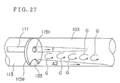
- the radiant tube burner 101 is allowed to operate as mentioned above, whose combustion state will be described using a schema shown in FIG. 27.
- Combustion air A2 having absorbed heat from a heat storage 117 to reach high temperature, passes through the combustion air passage 113 and is injected from the off-center combustion air injection port 133.
- fuel gas F is injected from a small-diameter hole 115c positioned apart from the combustion air injection port 133 and connected to a burner gun 111 and burns in the radiant tube 103 while rolled up in a self-circulating flow G formed by a high-speed jet of combustion air A2.
- fuel gas F is mixed with the self-circulating flow G mainly comprising exhaust gas and becomes a low-calory fuel, so that the flame temperature at the time of combustion is reduced and a low NOx content combustion can be implemented. Furthermore, since combustion reaction takes place on a high-speed air jet, combustion reaction is delayed and the extent of combustion reaction widens, so that combustion reaction energy is dispersed and the flame temperature is further reduced, thereby enabling a low NOx content to be implemented in combustion.
- the maximum temperature point of flame takes place at an intra-furnace position over the thickness of the furnace wall apart and accordingly thermal energy generated by combustion reaction is released into the furnace, so that an excessive rise in flame temperature can be prevented, thereby also enabling a low NOx content to be implemented in combustion.
- the mass flow rate is increased in the combustion reaction field as the self-circulating flow mainly consisting of exhaust gas is rolled up by the high speed air jet, thereby enabling a low NOx content to be implemented in combustion.
- the combustion temperature can be lowered and an amount of generated NOx can be reduced to an extremely small extent.
- COG coke oven gas
- the radiant tube burner 101 was so arranged that the switching of individual burners 105 between the operating state and the waiting state was repeated at an interval of time T, but is not limited to this and may also be so arranged that the temperature of individual heat storages 117 is monitored and operation and wait of individual burners 105 are switched when this temperature reaches a preset temperature.
- a burner 105 is so arranged that individual heat storages 117 are housed side by side on the lower side of the burner body 109, but the housed position of individual heat storages 117 is not limited to this except that it is only required to be situated in the main combustion air passage 113 or at a midway point of the air passage mechanism 110 connected thereto and heat storages 117 may be housed side by side, for example, around the burner gun 111.
- FIGs. 28A-28C show a fifth embodiment of regenerative radiant tube burner according to the present invention.
- FIG. 28A is a structural drawing of this regenerative radiant tube burner, while FIGs. 28B and 28C are sectional views taken along the line I-I and along the line II-II of FIG. 28A, respectively.
- This regenerative radiant tube burner has a structure that burners 202 are oppositely inserted into both ends of a U-shaped radiant tube 201.
- a burner 202 comprises a burner gun 205 incorporating a fuel passage 203 for supplying fuel to the center and a pilot combustion air passage 204 for supplying pilot combustion air to the circumference thereof, a combustion air passage 206 provided around the burner gun 205 and having a larger inside diameter than that thereof, a honeycomb-shaped ceramic made heat storage 207 placed at a halfway point of the combustion air passage 206, a turning vane 208 placed to front of the heat storage 207 similarly in a midway point of the combustion air passage 206 and having an angle of about 45 deg., a baffle 209 for preventing the backflow of fuel gas and a circulating-flow rolled up part 210 enclosed with the burner gun 205, the turning vane 208 and the baffle 209.
- the outside diameter of the combustion air passage 206 is somewhat smaller than the inside diameter of the radiant tube 201 so that a space for turned combustion air to spread outward is preserved.
- combustion exhaust gas is sucked in and passed through a heat storage 207 to accumulate sensitive heat possessed by combustion exhaust gas at the other burner 202.
- combustion air is passed through the accumulated heat storage 207 and preheated, then allowing fuel to burn by using a preheated combustion air.
- the other burner 202 stops the supply of fuel gas and exhausts the combustion exhaust gas having passed through the heat storage 207, so that the supply of combustion air and the exhaust of combustion exhaust gas are switched using the four way valve 211.
- combustion air is supplied to the combustion air passage 206 and is preheated to high temperature by absorbing the heat energy accumulated in the heat storage 207 while passing through the heat storage 207. Then, the combustion air is supplied with turning force from a turning vane 208 and becomes a turning flow 212.
- the flow velocity at the time of combustion air to be injected into the tube is about 50 m/s. Because of having a momentum, the combustion air becomes a flow along the inner wall of the radiant tube 201 under action of a centrifugal force. Because the combustion exhaust gas is sucked from the other burner, the combustion exhaust gas advances toward the other burner 202.
- fuel gas is supplied to the fuel passage 203 and is injected from the tip 203a of the fuel passage 203 into the radiant tube 201 at a flow velocity of about 100 m/s in a straight line but not diffusively.
- a space part based on the difference in diameter. Since the flow velocity of fuel/combustion air is higher than that of the subsequent combustion exhaust gas, this space part becomes relatively a negative pressure as compared with the combustion part.
- a part of combustion exhaust gas generated by combustion of fuel forms a circulating flow 214 toward the fuel passage opposed to the injection direction of fuel.
- the portion 213a of fuel flow 213 situated at the outermost side rides on this circulating current 214 of combustion exhaust gas, is conveyed in the direction of the turning flow 212 of combustion air and rolled up in combustion air, and burns.
- the inner portion 213b relative to the outermost portion 213a of fuel flow 213 advances in front of the outermost portion 213a, but since the circulating flow 214 of combustion exhaust gas advances while circulating, this portion also rides on the circulating flow 214 of combustion exhaust gas with a delay, is conveyed in the direction of the turning flow 212 of combustion air and rolled up in combustion air, and burns.
- the further inner portion 213c of fuel flow 213 also rides on the circulating flow 214 of combustion exhaust gas in a similar manner, is conveyed in the direction of the turning flow 212 of combustion air and rolled up in combustion air, and burns. Thus, combustion proceeds in sequence.
- the fuel injected from the fuel passage does not burn for a short period at one time but gradually burns so that a slow combustion takes place and the combustion temperature does not rise, thereby suppressing the generation of nitrogen oxides (NOx).
- NOx nitrogen oxides
- the nitrogen oxide content amounted to about 130 ppm and a large effect of reduction in NOx was obtained in the method of the present invention using the same conditions as with a conventional air two-stage combustion scheme in which 450 ppm of nitrogen oxides had been generated.
- the regenerative radiant tube burner mentioned above is provided with a circulating-flow inflow part 210 enclosed with the burner gun 205, the turning vane 208 and the baffle 209.
- the reason for provision of such a circulating-flow inflow part 210 is because it was experimentally confirmed that the circulating flow 214 of combustion exhaust gas flows in this circulating-flow inflow part 210 and lowers the temperature of combustion air by heat exchange therewith and at the same time the fuel gas riding on the circulating flow 214 of combustion exhaust gas is rolled up in the turning flow 212 from the starting point of the turning flow 212 of combustion air to burn, thereby suppressing the generation of nitrogen oxides (NOx) more efficiently.
- NOx nitrogen oxides
- the present invention is simplified in structure because of fundamentally comprising one fuel blow inlet and one air blow inlet, and applicable to all diameters of radiant tubes.
- the generated combustion exhaust gas reaches the other end of the radiant tube and passes through the turning vane, so that it passes through a heat storage placed opposite to the burner while turning in a direction of circumference.
- the turning vane operates to make the temperature distribution uniform. Accordingly, since the contained thermal energy is uniformly accumulated from the combustion exhaust gas having reached a heat storage and the temperature of the heat storage becomes more uniform, there is such an effect that higher-temperature preheated air can be obtained.
- honeycomb-shaped ceramic heat storage is employed and the layer of heat storage becomes thinner than that of an aluminum ball-shaped heat storage having the same thermal efficiency, and accordingly there is an advantage that the pressure loss of combustion air is small and combustion can proceed with a low motive force.
- the present invention can give a like arrangement/advantage also in respects of atomized liquid fuel.
- FIG. 30 shows a sixth embodiment of radiant tube burner according to the present invention.
- This embodiment is a trident type radiant tube burner, the radiant tube 310 is provided with tubes 301A-301C and regenerative burners A-C are provided at the end of these tubes, respectively.
- the respective burners A-C comprise heat storages 302a-302c and nozzles 306a-306c penetrating these heat storages, the sectional area of the tubes 301A-301C is overall a nearly equal circle.
- the nozzles 306a-306c are supplied via fuel electromagnetic valves 303a-303c with fuel and the combustion air is supplied via air electromagnetic valves 304a-304c into the tube 301A-301C.
- Combustion exhaust gas is arranged to be exhausted via exhaust gas electromagnetic valves 305a-305c to outside the furnace (tube).
- These electromagnetic valves 303a-303c, 304a-304c and 305a-305c are subjected an ON-OFF control by a control 307 provided with a sequence circuit.
- a pilot burner is provided at the end of each tube (not shown).
- FIG. 31 shows an alternate combustion operation of the embodiment of FIG. 30 and this operation is automatically controlled by the control 307.
- Burner A By igniting a pilot burner, Burner A burns and at that time the tubes 301B and 301C are set to a state that they can suck/exhaust combustion exhaust gas via the heat storages 302b, 302c.
- a combustion and extinguishment method of regenerative burners A-C first, fuel is supplied in a state of being supplied with combustion air to be ignited and extinguishment is made by shutoff of combustion air after a shutoff of fuel supply.
- a lag in the timing of supply between fuel and combustion air is 2 seconds.
- This time lag is one for air purge (air ventilation) of the combustion exhaust gas stuffed into the piping from the air electromagnetic valves 304a-304c to the burner, the heat storages 302a-302c and the like because of sucking in exhaust gas prior to combustion of individual burners.
- this time lag is a time required for replacement of combustion exhaust gas with air.
- Burner A is ignited and set to a combustion state, next Burner A is extinguished to set Burner B to a combustion state and then Burner B is extinguished to set Burner C to a combustion state. While switching a combustion state in sequence like this, the radiant tube burner is set to a predetermined temperature.
- combustion control will be described.
- Burner A combustion of Burner A will be described.
- the air electromagnetic valve 304a is turned to ON to supply combustion air into the tube 301A and at the same time the exhaust gas electromagnetic valves 305b, 305c are turned to ON to exhaust gas.
- the fuel electromagnetic valve 303a is turned to ON and fuel is supplied to start combustion.
- the combustion period of Burner A may be set in accordance with the heat accumulating capacity of heat storages 302a-302c and was set to 30 seconds in this embodiment.
- the fuel electromagnetic valve 303a is turned to OFF and at the time t 1 after the lapse of 2 seconds, the air electromagnetic valve 304a is turned to OFF to transit to combustion of Burner B.
- this stop period prior to the fuel supply was set to 2 seconds on the basis of combustion experiment results, but may be set to more than a time for fuel remaining in the piping from the fuel electromagnetic valve 303a to the burner nozzle to be completely injected due to the residual pressure and the order of at least 0.5 seconds is required.
- Burner B is subjected to an operation similar to that of Burner A. Referring to FIG. 31 (2), combustion of Burner B will be described.
- the air electromagnetic valve 304a is shut off and at the same time the exhaust gas electromagnetic valves 305a is turned to ON, the air electromagnetic valve 304b of Burner B is turned to ON to supply combustion air into the tube 301B.
- the exhaust gas electromagnetic valve 305c keeps an ON state.
- the fuel electromagnetic valve 303b is turned to ON, fuel is supplied and Burner B starts combustion.
- Combustion exhaust gas in the tube 301B is sucked in to the Burner A side and the Burner C side, the sensitive heat of combustion exhaust gas is accumulated in the heat storages 302a, 302c.
- the combustion air supplied from the air electromagnetic valve 304b passes through the heat storage 302b, is preheated with the recovery heat accumulated in the heat storage 302b during a period of t 0 -t 1 and supplied to Burner B.
- Burner C maintains a suction state of combustion exhaust gas
- the heat storage 302c accumulates the sensitive heat of combustion exhaust gas during a period of t 0 -t 2 .
- the fuel electromagnetic valve 303b is shut off and the air electromagnetic valve 304b is shut off at the time t 2 to set Burner B to an extinguished state.
- the exhaust gas electromagnetic valve 305b is tuned to ON and at the same time the air electromagnetic valve 304c is turned ON and exhaust gas electromagnetic valve 305c are turned OFF, respectively, so that a burning state of Burner B transits to a burning state of Burner C.
- the exhaust gas electromagnetic valve 305a keeps an ON state.
- Burner C turns the air electromagnetic valve 304c to ON at the time t 2 , the fuel electromagnetic valve 303c is turned to ON after the lapse of 2 seconds and combustion starts.
- a period of time when the air electromagnetic valve 304c remains ON, or the switching interval of alternate combustion, is 30 seconds and accordingly a period of time when the fuel electromagnetic valve 303c remains ON is 26 seconds.
- the exhaust gas valves 305a, 305b are ON and combustion exhaust gas is exhausted outside the furnace. At that time, the sensitive heat of exhaust gas is accumulated in the heat storages 302a, 302b.
- the combustion air supplied from the air electromagnetic valve 304c is preheated with the heat storage 302c and supplied to Burner C.
- Burner C is set to an extinguished state and Burner A is set to a combustion state.
- combustion is continued till the operation stop or pause of the radiant tube burner while Burner B, Burner C, ... are switched in sequence.
- the exhaust gas electromagnetic valves 305a-305c While the exhaust gas electromagnetic valves 305a-305c are kept ON, sensitive heat of exhaust gas is accumulated in the heat storage of their respective tubes and combustion air in the respective tubes is preheated with the recovered heat of the respective heat storage and is provided to combustion while the air electromagnetic valves 304a-304c are kept ON.
- the alternate combustion period is 30 seconds
- the time lag is 2 seconds
- the pause period prior to the fuel supply is 2 seconds, so that a period of time when the fuel electromagnetic valves 303a-303c are kept ON is 26 seconds.
- the thermal efficiency of a radiant tube burner is improved.
- combustion is continued while combustion tubes are switched in sequence.
- the radiant tube burner of the present invention is an alternate combustion equipment in which ignition/extinguishment are repeated at a short interval, a flame monitor is installed and safety measures are taken.
- a CO detector is installed in the exhaust gas flue to monitor incomplete combustion.
- FIG. 32 a seventh embodiment of the present invention will be described.
- the embodiment of FIG. 32 differs in the shape of radiant tubes from that of FIG. 30, but is otherwise identical and like symbols are given to like parts similar to those of FIG. 30.
- the radiant tube 310 comprises a trunk tube 310A and branch tubes 301A-301C extending from the trunk tube. At the end of the branch tubes 301A-301C, regenerative Burners A - C are provided.
- the fuel supply electromagnetic valves 303a-303c, the air electromagnetic valves 304a-304c for controlling combustion air and the exhaust gas electromagnetic valves 305a-305c are the same as those of the embodiment of FIG. 30, and the ON-OFF control thereof is carried out with a control device 307.
- the trunk tube 310A serves as an equalizer (header) for combustion exhaust gas flowing therethrough.
- Burners A-B burn alternately and, for example, even if combustion exhaust gas passes through the trunk tube 310A and passes respectively through trunk tubes 301A, 301C, the respective flow rates of branch tubes 301A, 301C become nearly equal.
- the relation is set as (sectional area in a trunk tube)/(sectional area in a branch tube) ⁇ 1.5 .
- Burners A-C perform alternate combustion operation as described in FIG. 31 and accordingly the description thereof will be omitted.
- FIG. 33 comprises four regenerative burners and the number of electromagnetic valves also increases corresponding to this number, but the fundamental arrangement is the same as with the embodiment of FIG. 32 and like symbols are given to parts similar to those of FIG. 32.
- the radiant tube 310 comprises a trunk tube 310A and branch tubes 301A-301D provided on the trunk tube 310A.
- H regenerative Burners A - D are provided at the end of the branch tubes 301A-301D.
- Burners A - D comprise heat storages 302a-302d and nozzles 306a-306d, respectively.
- fuel electromagnetic valves 303a-303d, air electromagnetic valves 304a-304d for controlling combustion air and exhaust gas electromagnetic valves 305a-305d are provided. These electromagnetic valves are controlled with a control device 307.
- the relation of sectional area between the trunk 310A and the branch tubes 301A-301D is set as (sectional area in a trunk tube)/(sectional area in a branch tube) ⁇ 2 .
- FIGs. 34 and 35 Combustion operation of this embodiment will be described referring to FIGs. 34 and 35.
- control of combustion is carried out by switching the burning burners A - D in the sequence of Burners A, B, C and D as shown in FIG. 34.
- combustion control of this embodiment for example, when one Burner A burns, combustion exhaust gas is so controlled as to be sucked to the other three Burners B - D sides.
- FIG. 35 shows a detailed timing chart thereof.
- (1) - (4) show combustion/exhaust operations of Burners A-D.
- Burner A First, operations of Burner A will be described referring to FIG. 35 (1).
- the air electromagnetic valve 304a is turned to ON.
- the fuel electromagnetic valve 303a is turned to ON to set Burner A to a burning state.
- Burners B, C and D turn the exhaust gas electromagnetic valves 305b - 305d to ON at the time t 0 to exhaust combustion exhaust gas to outside the furnace.
- the air electromagnetic valve 304a is turned to OFF at the time t 1 to set Burner A to an extinguished state
- the exhaust gas electromagnetic valve 305a is turned to ON and the exhaust gas electromagnetic valves 305c and 305d for Burners C and D keep an ON state.
- the air electromagnetic valve 304b is turned to ON, the fuel electromagnetic valve 303b is turned to ON to set Burner B to a burning state and at the same time the exhaust gas electromagnetic valve 305b to OFF.
- the air electromagnetic valve 304b is turned to OFF at the time t 2 to extinguish Burner B.
- the exhaust gas electromagnetic valve 305b is turned to ON, so that a burning state of Burner B transits to a burning state of Burner C.
- Burner C The combustion operation of Burner C will be described.
- the air electromagnetic valve 304c is turned to ON, the fuel electromagnetic valve 303c is turned to ON to set Burner C to a burning state and at the same time the exhaust gas electromagnetic valve 305c to OFF.
- the air electromagnetic valve 304c is turned to OFF at the time t 3 to extinguish Burner C.
- the exhaust gas electromagnetic valve 305c is turned to ON.
- Burner D operations of Burner D will be described.
- the air electromagnetic valve 304d is turned to ON, the fuel electromagnetic valve 303d is turned to ON to set Burner D to a burning state and at the same time the exhaust gas electromagnetic valve 305d to OFF.
- the air electromagnetic valve 304d is turned to OFF at the time t 4 to extinguish Burner D.
- the exhaust gas electromagnetic valve 305d is turned to ON.
- control of combustion may be also carried out in the sequence of Burners A, B, C and D.
- FIG. 37 comprises the respective regenerative burners provided corresponding to five branching tubes. Like symbols are given to parts similar to those of FIG. 33.
- the radiant tube 310 has branch tubes 301A - 301E provided for a trunk tube 310A and regenerative burners A - E provided at the end thereof.
- Burners A - E comprise heat storages 302a - 302e and nozzles 306a - 306e, respectively.
- fuel electromagnetic valves 303a-303e, air electromagnetic valves 304a - 304e for controlling combustion air and exhaust gas electromagnetic valves 305a - 305e are provided. These electromagnetic valves are controlled with a control device 307.
- FIG. 38 shows an example that two burners are allowed to burn and three burners are operated to suck in combustion exhaust gas.
- the ON-OFF operation of these electromagnetic valves is the same as that described above. Needless to say, it is evident that the operating pattern is not limited to that of FIG. 38 but may be another pattern.
- radiant tube burners according to the present invention were described by enumerating various embodiments, but any number of branch tubes may be provided for the trunk tube. And, a combination of burning burners and not burning burners is optional.
- radiant tubes with a circular sectional shape were employed; however, such a pipe-shaped arrangement is not required but a polygonal-section arrangement is also allowable.
- a fin-equipped arrangement for an increase in heat transmission area is also allowable.
- metal e.g., heat-resisting steel pipe
- a radiant tube may be made up of ceramics.
- any material is available if capable of maintaining a sufficient durability and is not required to be limited to these.
- FIG. 39 is a structural drawing showing the fundamental concept for verifying a combustion method of a radiant tube burner according to the present invention.
- Numeral 401 denotes a radiant tube burner, which is equal to a conventional in that gaseous fuel of hydrocarbon type is normally employed, the burner is heated by passing of combustion gas through the interior and heat is radiated from the outer surface to heat a heating furnace, heat-treating furnace or the like.
- Numeral 402 denotes a radiant tube for closing both ends and partitioning a space to form a combustion chamber.
- Numeral 403 denotes fuel injection ports provided at both ends of said radiant tube 402 and connected to a hydrocarbon type gaseous fuel piping.
- Numeral 404 denotes combustion air injection ports provided at both ends of said radiant tube 402, connected to a not shown air supply installation and exhaust installation and jointly used for air supply and for gas exhaust, where the other functions as a discharge port when the port of either one side functions as a charge port.
- Numeral 405 denotes a heat accumulating material stuffed in combustion air injection ports 404 and composed of globular ceramic, porous ceramic or other molded ceramic, which is deprived of heat by supply air when the combustion air injection port 404 functions as a supply port and is heated by exhaust gas when the combustion air injection port functions as a discharge port. As shown in FIG.
- a fuel injection port 403 has a slit shape for executing a high-speed mix of fuel with air and a combustion air injection port 404 has a circular shape for enlarging the self-circulating flow, both of which are positioned to be apart from each other.
- the fuel injection port 403 and the combustion air injection port 404 are both set off-center, but only either one may be set off-center.
- combustion of a radiant tube is alternately executed at both ends. That is, while one combustion air injection port 404 is burning, the other combustion air injection port 404 is made to function as a discharge port of combustion gas and heat is allowed to be accumulated in a stuffed heat-accumulating material. After a sufficient accumulation of heat, combustion is stopped once, the combustion air injection port 404 having functioned as a discharge port is made to function as an air charge port and preheating of air is carried out with heat accumulated in the heat-accumulating material.
- the charge speed of combustion air supplied from the combustion air injection port 404 is made substantially larger than that employed in a conventional radiant tube burner, vortex flow is generated near the extension direction of the fuel injection port 403 and a self-circulating flow is derived in combustion gas to dilute a high-temperature combustion gas and lower the combustion temperature, and moreover the generation time of nitrogen oxides determined from the length of a radiant tube and the flow velocity of combustion gas is shortened to keep the reaction in a non-equilibrium state, thereby decreasing the nitrogen oxide content in exhaust gas.
- Preventing the combustion reaction from proceeding to an equilibrium state can be attained by shortening the stay time of the high-temperature part with the velocity of gas flow retained.
- the locally generated portion with an air ratio of 1.0 is greatly decreased and the combustion time in a radiant tube is made shorter than a period for a perfect completion of combustion reaction, so that the combustion in a radiant tube can be kept non-equilibrium.
- the radiant tube (402) is a straight tube.
- Table 4 shows the results obtained by a 20-second-interval intermittent combustion as shown in FIG. 41 with a mean combustion gas rate of 50 m/s at the radiant tube outlet in a radiant tube (402), 2 m in length and 100 mm in tube diameter. It is evident from these results that the present invention can achieve a lower nitrogen oxide content and a higher combustion efficiency than those of a conventional combustion method.
- Table 4 Maximum temperature (°C) Nox generated quantity (ppm) Conventional example 1800 700 Present invention 1750 100
Landscapes
- Engineering & Computer Science (AREA)
- Chemical & Material Sciences (AREA)
- Combustion & Propulsion (AREA)
- Mechanical Engineering (AREA)
- General Engineering & Computer Science (AREA)
- Combustion Of Fluid Fuel (AREA)
- Gas Burners (AREA)
Abstract
Description
- The present invention relates to a radiant tube burner and a combustion method thereof used in industrial heating furnaces and heat treatment furnaces for heating materials.
- Recently, attempts have been made to apply the regenerative combustion to a radiant tube burner. Regenerative combustion is carried out in such a manner that air for combustion is preheated with combustion exhaust gas by using a heat storage member and this air for high-temperature combustion is utilized for combustion. And at that time, a burner of alternate combustion type is considered in which burners, attached individually at both ends of the radiant burner, are allowed to burn alternately and the combustion exhaust gas of one burning burner is discharged through the air throat of the other burner at pause. With the radiant tube burner of regenerative alternate combustion type, the air throat of each burner, connected to the respective heat storage, serves as the supply passage of air for combustion and as the exhaust passage of combustion exhaust gas at the pause of combustion. And, each heat storage collects heat when a combustion waste gas passes by it and preheats air for combustion to high temperatures near the temperature of combustion waste gas with stored heat when air for combustion passes by it.
- However, generally when the regenerative combustion is carried out, the preheated temperature of air for combustion reaches a high temperature, i.e., 800°C or higher and NOx increases. For this reason, suppressing the generation of NOx is considered by employing so-called the fuel two-stage combustion (US Patent NOs. 4,856,492 and 4,870,947) in which fuel is injected into the flow of air for combustion at two steps to cause a combustion or so-called the air multi-stage combustion in which air is injected into fuel at two steps to cause a combustion.
- With the radiant tube burner, however, any of the above combustion schemes is difficult to execute since a fuel nozzle is generally inserted in a heat-resistant alloy radiant tube of as small caliper as 90-200 mm to form an air throat. To be concrete, with the two-stage fuel combustion scheme, though provision of a secondary fuel nozzle for injecting a secondary fuel is required downstream of the primary combustion, it is extremely difficult to have a secondary fuel nozzle provided outside or inside the primary combustion chamber in a narrow space of the radiant tube. And with the air multi-stage combustion method, to employ a double cylinder structure is indispensable to assure a passage for supplying a secondary air downstream of the primary combustion zone, but the placement thereof is extremely difficult in the radiant tube with a restricted space. Thus, the reduction principle of NOx in each of the above-mentioned combustion methods is difficult to make the best of.
- In addition, there is another problem that implementation of the fuel two-stage combustion method or the air multi-stage combustion method requires a primary and secondary fuel supply systems or air supply systems and not only the control of them but also the structure of burners becomes complicated.
- Furthermore, with a burner system in which alternate combustion is performed, fuel is left in the fuel nozzle of a not burning burner as a result of burner structure. Thus, unless the heat isolating structure of a fuel nozzle is sufficient, a problem of so-called coking is involved that the residual fuel is heated and carbonized due to a high-temperature combustion exhaust gas exhausted through an air throat.
- And, among various inventions made for preventing the generation of NOx, Japanese Patent Application Laid-Open No. 62-242711, for example, discloses that addition of water in a burner enables the generation of NOx to be reduced. Or, Japanese Patent Application Laid-Open No. 63-116011 discloses that a high-load combustion based on a turning flow of primary air permits a good and stable combustion and a soft two-stage combustion in a radiant tube enables the generation of NOx to be reduced. Or, Japanese Patent Application Laid-Open No. 3-11202 discloses that, provision of a Venturi mechanism and recirculation of exhaust gas under control of flow rate enable the generation of NOx to be reduced.
- With a radiant tube burner, however, each of the above-mentioned combustion methods is difficult to implement because a burner gun is inserted into a radiant tube of relatively small diameter. That is, with the fuel two-stage method, for allowing a secondary fuel to burn downstream after combustion of a primary fuel, provision of a fuel supply passage outside (or inside) the primary combustion chamber is necessary which extends to the secondary fuel injection port. And with the air multi-stage combustion method, to lead a secondary air to downstream of a primary combustion region is necessary and a double-structured air passage must be provided. For these reasons, implementation of the individual combustion methods mentioned above requires a large-sized and complex-structured burner itself, so that the above combustion methods were hardly applicable to a radiant tube burner.
- Implementation of the fuel two-stage combustion method or the air multi-stage combustion method requires not only control of the fuel supply and air supply systems leading to a pilot burner, but control of either the primary and secondary fuel systems and the air system or the primary and secondary air systems and the fuel system and therefore causes a problem that control of these systems becomes complicated as well.
- Furthermore, with a burner for alternate combustion, fuel never fails to remain in the fuel passage of a burner on the non-operating side for a structural reason. There was a problem that, when a high-temperature exhaust gas is exhausted via a burner on the non-operating side, a residual fuel in the fuel passage is heated and carbonized, or so-called coking takes place.
- The above method of Japanese Patent Application Laid-Open No. 62-242711, can lower the flame temperature because combustion gas is directly cooled. However, since a heat quantity corresponding to the latent heat of evaporation of added water and the sensitive heat taken out by water vapor released as exhaust gas must be extra supplied as compared with a case of no added water, the thermal efficiency decreases. With the method of Japanese Patent Application Laid-Open No. 63-116011, since re-combustion (secondary combustion) is performed with air being supplied after a low-air-ratio combustion (primary combustion), the flame temperature can be lowered below that of normal combustion, but no effect is attainable unless flow control is made with good accuracy. For implementation, there are defects such as an increase in cost of repair, and maintenance to maintain the optimum point. Or, with a method for allowing fuel gas to burn by using air mixed concentrically with exhaust gas in an exhaust-gas-circulating cylindrical radiant tube according to Japanese Patent Application Laid-Open No. 3-11202, a low NOx combustion can proceed by lowering the flame temperature and oxygen concentration in the field of combustion, but there are defects such as an increase in installation cost and repair cost because the mechanism including a burner is complicated and equipped with attachments.
- In addition, though the upper limit of preheated-air temperature was about 500°C according to a conventional recuperator method, the method of Japanese Patent Publication No. 2-23950, relevant to the art wherein the alternate combustion mentioned above made it possible to obtain a preheated-air temperature of more than 900°C, has a problem that, as compared with a conventional method, a considerable rise in the temperature of preheated air elevates the flame temperature and increases the quantity of generated NOx.
- Meanwhile, the present authors found that the quantity of generated NOx is inversely proportional to the flow velocity of combustion air (cf. FIG. 1). In applying this result to a conventional radiant tube burner, the temperature of preheated air obtained by the recuperator method applied to a conventional radiant tube burner is on the order of 500°C and this preheated air has no ignition energy sufficient for COG (Coke Oven Gas; ignition temperature on the order of 500 - 600°C) and LNG (ignition temperature on the order of 550 - 650°C) to be used as fuel for a radiant tube burner. Thus, the quantity of thermal energy radiated to the surroundings exceeded that of thermal energy generated by combustion reaction, so that no stable formation of a stable temperature are that can be combusted, was possible, no stable combustion could proceed, lifting or blown extinguishment of flame took place and no burner using combustion air with high flow velocity was made fit for practical use.
- At a preheated-air temperature of about 500°C obtained by the recuperator, a conventional burner for a low-NOx combustion method, wherein the flow velocity of combustion air is set to about 50 - 60 times the combustion speed of fuel, a intra is applied to a furnace in which a high-temperature preheated air on the order of 930°C is obtained at an intra-furnace temperature of 900°C and a coke furnace gas mixed with fuel gas and air in the air ratio of about 1.3 at one time is employed as a fuel gas for combustion. After an incomplete combustion done at the first stage, exhaust gas at the first stage is allowed to undergo perfect combustion at the second stage. FIG. 2 shows the experimental results on the relation between pre-heated air temperature and the NOx content in exhaust gas obtained by the inventors in such a two-stage combustion method, which reveals that a low NOx combustion cannot be sufficiently fulfilled in the two-stage combustion.
- Since a preheated air of higher temperature is employed for blow-in of vapor or water than that employed in a conventional method, the blown-in quantity must be increased and there are problems such as an increase in running cost and a rise in equipment cost due to a decrease in thermal efficiency. Even when the exhaust gas circulation method is employed, to fulfill a low NOx combustion with a high-temperature preheated air, as shown in FIG. 3, there are problems such as an increase in power cost for circulating fan due to an increased amount of exhaust gas circulation and a rise in installation cost and repair cost due to a more complicated equipment and moreover an economically effective reduction of the Nox concentration in exhaust gas is hardly implementable on account of a rise in flame temperature due to a high-temperature preheated air.
- A basic reason for a high combustion temperature in combustion of a radiant tube burner is that the highest region in combustion temperature with an air ratio of about 0.95 - 1.00 is localized. Based on many combustion experiments and numerical simulations of combustion, the inventors compared and examined a case of combustion at air ratios of 1.4 and 4.0 in a premix combustion that a premixed gas of fuel and air is allowed to burn and a case of combustion at air ratios of 1.4 and 4.0 in a diffuse combustion that separately supplied fuel and air are allowed to burn. As shown in FIG. 4, it is found from the results that, whereas the maximum combustion temperature in the combustion region varies substantially for a premix combustion, the maximum combustion temperature differs little for a diffuse combustion. That is, a comparative study revealed that, for a diffuse ratio, the region with an air ratio of nearly 1 is locally present in the mixture portion of fuel and air even at a large air ratio and a gas burning in this region reaches a high temperature, no region with an air ratio of nearly 1 is observed anywhere for a premix combustion, so that the maximum combustion temperature depends on the air ratio.
- Because of a fear of explosion in industrial applications, however, a premix combustion is normally unemployed and consequently reduction of generated NOx must be fulfilled for a diffuse combustion.
- It is one object of the present invention to provide a radiant tube burner of simple structure, enabling the generation of NOx to be suppressed, the control of the fuel supply system and air supply system to be simplified and the coking of fuel to be prevented.
- Furthermore, a burner of regenerative Application radiant tube scheme typified by (1) Japanese Utility Model Application Laid-Open No. 2-23950 has recently been disclosed which attains a high thermal efficiency with exhaust heat recovery implemented by applying the regenerative heat exchange to this radiant tube burner.
- A burner of such scheme will be described referring to FIG. 5. A
radiant tube burner 320 comprisesheat storages 312 provided at ends of aradiant tube 311 andnozzles 313 so arranged as to penetrateheat storages 312 wherein the supply of fuel and the exhaust of exhaust gas are performed via a change-overcontrol valve 314. The sensitive heat of combustion exhaust gas is accumulated in aheat storage 312 when combustion exhaust gas passes through theheat storage 312 and heat accumulated in theheat storage 312 is allowed to transmit to combustion air, which is supplied to inside the furnace as a high-temperature preheated air, when combustion air passes through theheat storage 312, thereby attaining a high heat efficiency. By alternate combustion of regenerative burners provided at ends of aradiant tube 311 through repetition of a burning state and not burning state, the thermal efficiency is raised. - In addition,
burners 313 provided at both ends are allowed to burn alternately. Thus, though a temperature distribution took place along the longitudinal direction of a radiant tube in a conventional radiant tube burner with a burner allowed to burn at one side end alone, the longitudinal temperature distribution of a radiant tube is improved by alternate combustion of burners provided on both ends, so that there is an advantage that the service life of a radiant tube is prolonged. - Also, in (2) Japanese Utility Model Application Laid-Open No. 6-65705, a trident type regenerative radiant tube burner is proposed. Description will be made referring to FIG. 6. The
radiant tube 311 comprises acombustion tube 315 and a pair ofreturn tubes 316, wherein aburner 313 is provided on the end of thecombustion tube 315 andheat storages 312 are provided on the respective ends of bothreturn tubes 316. With this regenerativeradiant tube burner 322, combustion air is supplied directly to theburner 313 and at the same time is heated while passing through theheat storages 312 to be supplied to theburner 313, whereas combustion exhaust gas is exhausted to outside the furnace after accumulating its sensitive heat in theheat storages 312. In eachheat storage 312, an exhaust passage and a combustion air passage are perpendicularly formed in such a manner that combustion exhaust gas and combustion air cross. - However, with the regenerative radiant tube burner of conventional example (1), the pressure loss in passing of combustion air/combustion exhaust gas through a heat storage exceeds that of a recuperator (metal heat exchanger method). Thus, there is a disadvantage that the pressure-saving capability of a combustion air blower and combustion exhaust gas suction fan must be increased, thereby resulting in a larger size of equipment. In addition, though energy-saving effect is obtained in view of thermal efficiency, there is another disadvantage that power cost required for blower equipment used in combustion plant rises.
- On the other hand, with the trident type regenerative radiant tube burner of conventional example (2), since the tube of burning state is always one and the same, it contributes to a rise in heat efficiency of the regenerative radiant tube burner but nevertheless uniformized longitudinal temperature distribution of the radiant tube by alternate change-over combustion (alternate combustion) cannot be sufficiently achieved. Thus, there are disadvantages that an anomalous thermal stress acts on the radiant tube owing to a non-equilibrium temperature distribution, so that repeated strain of the radiant tube makes breakage likely to take place and the effect of prolonging the service life cannot be fully produced.
- For solving these problems, it is another object of the present invention to provide a radiant tube burner in which the power cost of a combustion air blower and a combustion exhaust gas suction fan can be reduced and the longitudinal temperature distribution of a radiant tube can be made more uniform by a decrease in the pressure loss of a regenerative radiant tube.
- At the same time, it is a further object of the present invention to provide a radiant tube burner in which fuel gas is allowed to undergo a perfect combustion, thereby enabling thermal efficiency of a radiant tube burner to be improved.
- A radiant tube burner according to the present invention is a radiant tube burner allowing a burner to burn by using high-temperature combustion air obtained by alternately passing combustion waste gas and combustion air through a heat storage, wherein a fuel nozzle for injecting fuel and an air throat for injecting the combustion air are arranged in parallel in the end of a radiant tube and a tip opening of the air throat is so arranged as to deviate in contact with or near to the inner circumferential wall surface of said radiant tube as well. Here, in the radiant tube burner according to the present invention, it is preferable to employ a pilot burner joint-use nozzle as the nozzle, it is preferable to bring the injection port of the air throat into internal contact with the inner wall surface of the radiant tube burner and further it is preferable to divert the fuel nozzle from the center to a direction opposed to the combustion air injection port within such limits as not to internally touch the center of the radiant tube or the inner circumferential wall surface.
- In addition, with a radiant tube burner according to the present invention, while having a nozzle support for stop up the radiant tube provided at the tip of the air-throat tube inserted into the radiant tube in one piece and a combustion-nozzle through hole for supporting the inserted tip of the fuel nozzle provided on the nozzle support, it is preferable to have a through hole internally touching the inner wall surface of the radiant tube provided on the rim of the nozzle support and to allot the through hole to a combustion air injection port of the air throat. And, in a radiant tube burner according to the present invention, it is preferable to allot a hole formed by the air throat formed between the radiant tube and fuel nozzle along with the circumferential groove of the nozzle support and the inner wall surface of the radiant tube to the tip opening of the air throat, with a nozzle support having a fuel-nozzle through hole for stopping up the radiant tube and for supporting the inserted tip of the fuel nozzle and a groove internally touching the inner wall surface of the radiant tube provided on the radiant tube.
- Meanwhile, the heat storage to be used for a radiant tube burner according to the present invention is preferably a honeycomb-shaped ceramics through which a flow passage passes in a constant passage area and linearly.
- Furthermore, in the present invention, an alternate-combustion type radiant tube burner is so arranged that burners arranged like these are installed at both ends of the radiant tube and combustion waste gas is exhausted through the air throat of the not burning burner. And it is desirable for this alternate-combustion type radiant tube burner to use a pilot burner joint-use nozzle as the fuel nozzle. It is desirable for this pilot burner joint-use nozzle that while a suitable amount of primary air for pilot combustion is made to always flow independently of the working state of a burner with the primary air passage being provided for allowing primary air to flow around the fuel nozzle, a sufficient amount of fuel for maintaining the pilot flame is always flowed as pilot fuel and at the same time the amount of injection fuel is switched at combustion and at pause of combustion in such a manner that the main combustion and the pilot combustion succeed to each other.
- Such being the case, with a radiant tube burner as set forth in
Claim 1, combustion air is injected along the tube wall of the radiant and the flow thereof is unevenly distributed but not over the whole transverse section. Consequently, a negative pressure is generated on the opposite side to the injection portion of combustion air, thereby causing a strong recirculation of exhaust gas, and at the same time the exhaust gas and combustion gas injected in parallel with combustion air are induced by and follow the flow of combustion air, so that a slow combustion occurs with a gradual rolling up of both gases in the flow of combustion air. - That is, the combustion air preheated to high temperatures, e.g., about 800°C or higher, is injected at considerably higher speed than that of a normal-temperature fuel because the volume is expanded as compared with the time of normal temperature. For example, in contrast to fuel injected at velocities of 20-30 m/s, a high-temperature preheated air is injected at an extremely high velocity of 100 m/s or higher. Accordingly, fuel does not spread in the tube but is induced by the high-speed flow of combustion air to flow along the inner wall of the tube and is gradually rolled up into the air flow of combustion air with the lapse of time. In addition, part of combustion exhaust gas to counterflow to the neighborhood of the injection port in the radiant tube is directly induced by the flow of combustion air to be rolled up, thereby decrease the oxygen concentration, or sometimes rolled up between fuel injection flow and combustion-air injection flow, thereby preventing these from immediately contacting each other. Thus, they can form a long flame while burning slowly and consequently can heat the tube with a uniform heat flux, thereby permitting a long service life of the radiant tube.
- With a radiant tube burner as set forth in
Claim 2, a pilot flame is ceaselessly formed at the root of combustion jet and accordingly a flame is stably formed even if combustion air and fuel are injected in parallel, so that a low NOx content can be achieved by increasing the roll-up amount of combustion exhaust gas. - With the invention as set forth in
Claim 3, exhaust gas is rolled up between the flow of combustion air and that of fuel, thereby preventing both of them from contacting each other directly after the injection and decreasing the oxygen concentration of combustion air in the diffusion portion of fuel, so that generation of NOx can be suppressed to a still greater extent. - With the invention as set forth in
Claim - With the invention as set forth in
Claim 6, since a honeycomb-shaped ceramics is used as the heat storage, the stagnant flow of combustion air or exhaust gas can be eliminated and moreover since two opposite-directioned flows of exhaust and charging occur alternately, the self-cleaning operation (backwash) works, so that deposition of dust in exhaust gas can be prevented into the heat storage. - Furthermore, with the invention as set forth in
Claim 7 wherein the above burners are provided at both ends of the radiant tube in such a manner as to burn alternately, upgrading the thermal efficiency can be achieved and combustion exhaust gas having passed through the radiant tube is exhausted through the air throat of a burner during the pause of combustion and led to the heat storage. - With the radiant tube burner as set forth in
Claim 8, since the not burning fuel nozzle of the radiant tube burner forms a pilot flame, the fuel nozzle itself is cooled with primary air and fuel and can be prevented from being heated with high-temperature combustion exhaust gas, so that occurrence of coking can be checked. Besides to this convenience, it is only necessary for actuating a burner during the pause to switch the flow of combustion air over to flow toward the burner throat on one side and increase the amount of fuel to flow into the fuel nozzle on the other hand. - Furthermore, a radiant tube burner according to the present invention is characterized in that the combustion air injection port or/and the fuel injection port is/are placed off-center in such a manner that they are kept apart from each other in the inside diameter direction.
- Another feature is that the transverse-direction shape of the combustion air injection port is circular.
- Still another feature is that the maximum temperature point of a flame generated by the combustion reaction takes place in the furnace at a position above the furnace wall thickness distant from the furnace wall on which the radiant tube is supported.
- Yet another feature is that the temperature of air injected from the combustion air injection port is 100°C or higher than the ignition temperature of fuel.
- Yet another feature is that combustion air is injected at as high speed as not less than 110 times the combustion speed of fuel.
- Yet another feature is that the discharge opening of the combustion air injection port or the fuel injection port are deviated from the center and the flow velocity of combustion air for allowing a mixture gas comprising carbon monoxide and a hydrocarbon compound portion to burn is set to 110 m/sec or higher.
- With the radiant tube burner as set forth in
Claim 9, a vortex flow due to an eccentric flow of air injected from the combustion air injection port or/and due to an eccentric flow of fuel injected from the fuel injection port is generated, so that the self circulation of exhaust gas is caused in the radiant tube. As a result, exhaust gas is flown back to envelop combustion air or/and to be mixed into combustion air, thereby diluting it, so that combustion in the radiant tube proceeds slowly, the combustion reaction time is delayed, a local high-temperature portion is decreased and the present time of the high-temperature portion is shortened, thereby enabling the generation of NOx to be reduced. In propotion to a distance due to eccentricity of the combustion air injection port and the fuel injection port, degree of decrease in NOx concentration in exhaust gas increases. And since it is sufficient to place a burner gun and a combustion air passage in the radiant tube burner, a burner can be formed in a fine shape and an appropriate radiant tube burner can be formed. - With the invention as set forth in
Claim 10, since the combustion air injection port is circular, the outer peripheral length of injected combustion air becomes minimum as compared with the other shapes and accordingly a formed combustion reaction surface becomes small, the combustion reaction distance extends and combustion occurs over a wide area, so that the combustion reaction can proceed moderately, the local high-temperature region in flame can be widen and reduced in temperature, thereby enabling the generation of NOx to be decreased. - With the invention as set forth in
Claim 11, since the maximum temperature point of a flame generated by the combustion reaction is so arranged as to take place at an in-furnace position above the furnace wall thickness distant from the burner side, the thermal energy generated by the combustion reaction is released into the furnace, so that an excessive rise in flame temperature can be prevented, thereby enabling the generation of NOx to be decreased and the service life of the whole radiant tube burner to be prolonged. - With the invention as set forth in
Claim 12, since the temperature after the mixing can be maintained above the ignition temperature of fuel even if a decrease in temperature takes place, occurrence of an accidental fire due to a burst of flame or a blown leap of flame can be prevented. That is, the temperature of a preheated combustion air decreases directly before the combustion on account of mixing into fuel gas and heat diffusion to the periphery, but use of high-temperature preheated air (more than 100°C higher than the ignition temperature) made it possible to burn stably in an air of high speed not less than 110 times the combustion speed. The ignition temperature of COG used as fuel for a radiant burner is on the order of 500-600°C and that of LNG is on the order of 550-650°C. By using a preheated air of at least 100°C higher temperature than these temperatures, the high temperature preheated air can be provided with two requisites comprising oxygen and ignition source out of the three requisites for combustion (combustibles, oxygen and ignition source), so that occurrence of an accidental fire due to a burst of flame or a blown leap of flame can be prevented and a forced mixing of air and fuel gas in the burner becomes unnecessary as well. Thus, a moderate combustion reaction can proceed over a wide area in the radiant tube, the local high-temperature region can be widen and reduced in temperature, thereby enabling the generation of NOx to be decreased. - With the invention as set forth in
Claim 13, the flow velocity of combustion air is set to at least 110 times the combustion speed of the fuel to be used to increase the degree of the combustion gas diluted with self-circulated exhaust gas. As a result, the locally occurring high-temperature portion with an air ratio of 1.0 can be reduced greatly. By assuring the gas flow velocity to some extent and shortening the lasting time of the high-temperature so that combustion reaction in that portion does not proceed at high speed, the flame temperature can be lowered. With rising preheated air temperature, the NOx concentration in exhaust gas increases (cf. FIG. 2), but this increasing NOx concentration in exhaust gas can be decreased by raising the flow velocity of combustion air (cf. FIG. 1). This means that decreasing the generation of NOx is achieved by making the combustion time in the radiant tube shorter than the time taken till the combustion reaction is completely terminated and leading the combustion in the radiant tube to non-equilibrium state. The quantity of NOx in exhaust gas is decreased by maintaining the reaction in non-equilibrium state in such a manner that the generation of NOx determined from the length of the radiant tube and the flow rate of exhaust gas are shortened in time. - Meanwhile, with the air flow velocity of at least 110 times the combustion speed, the amount of thermal energy released to the surroundings surpasses the amount of thermal energy generated in combustion reaction and the lifting or blown out of a flame take place, but use of a preheated air of at least 100°C or higher temperature than the ignition temperature prevents this and a stable combustion state is obtained.
- Also when the flow velocity of fuel gas is raised, a decrease in the NOx concentration of exhaust gas is observed but the decreasing effect of NOx is smaller than that due to an increase in the flow velocity of combustion air. This can be conjectured to be attributed to the difference in the momentum of injection gas represented by (density) × (flow velocity)2, derived from the density difference between fuel gas and air.
- Incidentally, the combustion speed of COG and LNG (town gas 13A) as fuel is calculated in accordance with the following formula:
- Letting SM be the combustion speed of fuel gas,

- [Sb]i :
- Maximum combustion speed of a simple gas;
- Mi :
- Optimal combustion reaction air coefficient of a simple gas;
- Ai :
- Theoretical air amount of a simple gas;
- Xi :
- Vol % of a simple combustible gas;
- fi :
- Combustion speed attenuation coefficient of a simple combustible gas due to an inert gas;
- [N2] :
- Vol % of N2 in the mixed fuel gas;
- [O2] :
- Vol % of O2 in the mixed fuel gas; and
- [CO2] :
- Vol % of CO2 in the mixed fuel gas.
- The constants of ombustible simple gases required for the calculation of SM shown in the above formula (1) are shown in Table 1, whereas the combustion speeds computed of COG and LNG are shown in Table 2.
- As described above, the relation between the NOx concentration in exhaust gas and the flow velocity of combustion air depends on species of fuels, but if the ratio of the combustion velocity of the fuel to the combustion air flow velocity is arranged in conjunction with the NOx concentration in exhaust gas, an approximate correlation can be found out, thereby enabling low NOx combustion burners to be designed corresponding to various fuels.
[TABLE 1] Constants of Individual Combustible Simple Gases Required for the Calculation of SM H2 CO CH4 C2H4 C2H6 C3H6 C3H8 C4H10 [Sb]i 280 100 38 67 43 50 42 38 Mi 0.5 0.4 1.1 0.85 1.15 1.1 1.15 1.15 Ai 2.38 2.38 9.52 14.28 16.66 21.42 23.8 30.94 fi 0.75 (1.0) 0.5 0.25 0.22 0.22 0.22 0.18 [TABLE 2] Fuel Combustion Speed COG 78.0 cm/s Town Gas 13A 38.5 cm/s - With the invention as set forth in
Claim 14, the discharge opening of a combustion air injection port or/and a fuel injection port is/are placed off-center, the flow velocity of combustion air is set to 100 m/sec or higher and a great quantity of exhaust gas is allowed to undergo a self-circulation in a radiant tube. On diluting fuel gas with this self-circulating exhaust gas, the flame temperature falls. By allowing a mixture gas of hydrogen, carbon monoxide and hydrogen compounds to burn under such conditions, the generation amount of NOx decreases and can be reduced to a desired value (cf. FIG. 7). - In addition, by greatly decreasing the locally generating portion with an air ratio of nearly 1.0 and assuring the flow velocity of combustion air so that combustion reaction in that portion does not proceed at high speed, the lasting time of the high-temperature portion is shortened.
[TABLE 3] Maximum Amount of combustion temperature Generated NOx Conventional example 1,800°C 700 ppm Present example 100 m/s supply of air 1,700°C 200 ppm 200 m/s supply of air 1,620°C 100 ppm - The radiant tube burner as set forth in
Claim 15 a radiant tube burner with the respective regenerative burners provided at both ends thereof, comprising fuel passages provided at the radial center of the respective burners, combustion air passages having a greater inside diameter than that of the fuel passages provided outside them, heat storages provided halfway in the combustion air passages, and turning means subsequent to the heat storages for injecting combustion air preheated therewith while turning it. - The invention of
Claim 16 is a radiant tube burner characterized in that a circulating current inflow sections for allowing the circulating flow of combustion exhaust gas to inflow are provided between the fuel passages and the turning means. - In these inventions, after preheated while passing through a heat storage at one end of a radiant tube, combustion air is injected from a combustion air passage into a radiant tube while turning force is given with turning means and advances along the inner wall of a radiant tube by a centrifugal force.
- On the other hand, combustion gas (described in the case of gas fuel) is injected linearly and at high velocity toward the tube core of a radiant tube through the fuel passage of a combustion burner center. Since the inside diameter of the turning current of combustion air becomes larger than the outside diameter of the flow of fuel gas, the portion of relatively negative pressure takes place along the longitudinal direction of a radiant tube between both of them and a circulating current of combustion exhaust gas is formed in opposition to the injection direction. The fuel gas of the outermost portion in the flow of injected fuel gas, as if riding on and drawn back by this circulating current of combustion exhaust gas, is rolled up into the turning current of combustion air and mixed with combustion air to burn.
- Since the circulating current of fuel exhaust gas advances to the front while circulating, the fuel gas positioned inside the first rolled fuel gas in the fuel gas flow rides on this circulating flow in the front of the position where the fuel gas first rode on the circulating current of combustion exhaust gas is then rolled up into the combustion air and mixed with combustion gas to burn.
- In this manner, fuel gas does not burn at one time, but begins to burn in sequence from the nearest portion to the turning current of combustion air in the flow of fuel gas and accordingly combustion proceeds slowly and the combustion temperature does not become high, thereby preventing the generation of nitrogen oxides (NOx).
- Furthermore, when a circulating current inflow section for allowing the circulating flow of combustion exhaust gas to inflow are provided, fuel rides on this circulating current of combustion exhaust gas and flows into the circulating current inflow section to lowers the temperature of combustion air by heat exchange with combustion air and fuel is mixed with combustion air to burns from the stating point of the turning current of combustion air, so that the above slow combustion is further enhanced, thereby preventing the generation of nitrogen oxides (NOx) more effectively.
- The invention of
Claim 17 is a radiant tube burner characterized in comprising at least three burners, wherein exothermic reaction (combustion) is allowed to proceed dispersedly while switched and consequently the temperature distribution can be made uniform in the longitudinal direction of the radiant tube. - The invention of
Claim 18 is a radiant tube burner comprising a trunk tube and at least three branch tubes linked to the trunk tube, characterized in that a burner is provided at the end of each branch tube, which provision enables the temperature distribution to be made uniform in the longitudinal direction of a branch tube in the radiant tube and the service life of the radiant tube to be prolonged. - The invention of
Claim 19 is a radiant burner characterized in that the inner sectional area of the trunk tube is larger than that of the branch tube, which difference lowers the flow velocity of combustion exhaust gas in the trunk tube, decreases a pressure loss generated by the flow of combustion gas in the trunk tube (pressure loss due to the friction of flow) and equalizes the combustion exhaust gas pressure between each branch tube and the trunk tube for discharging combustion exhaust gas, so that balance between inflow amount and discharge amount of combustion exhaust gas can be made uniform and a pressure loss of the radiant tube can be decreased. - In addition, the invention of
Claim 20 is a radiant tube burner characterized in that a burner is provided with a heat storage, which provision enables the longitudinal temperature distribution in branch tubes of a radiant tube to be made uniform and the thermal efficiency to be further enhanced. - And, the invention of
Claim 21 is a radiant tube burner characterized in the alternate combustion by repetition of combustion and non-combustion at a certain period, which mechanism enables the collection of sensible heat of combustion exhaust gas and the release of collected sensible heat to combustion air in the heat storage, so that a heat storage type heat exchange becomes possible to provide a combustion equipment with a high thermal efficiency. Furthermore, alternate combustion of burners placed at individual blanch tubes makes it possible that combustion and exhaust are controlled to be repeated at a similar time division in such a manner that the flame is not at all time present in a certain tube and no difference in surface temperature occurs between the branch tubes, and consequently the temperature distribution of a radiant tube can be made uniform and the thermal efficiency can be further raised. - And, the invention of
Claim 22 is a radiant tube burner characterized in that the burners burn alternately and are provided with a controller for controlling the alternate combustion to proceed in an arrangement with a smaller number of burning burners than that of not burning burners, wherein fuel undergoes perfect combustion, the longitudinal temperature distribution of branch tubes of a radiant tube can be made uniform and the thermal efficiency can be further raised. - To be more illustrative, in the radiant tube burner, heat storages are placed at both ends of the radiant tube, and combustion air and combustion exhaust air are alternately exhausted. At that time, since combustion exhaust gas is supplied into each heat storage in counterbalance with the flow rate of combustion air passing through the heat storage, the flow velocity of gas passing through the heat storage per unit time is greater for passing of combustion exhaust gas than for passing of combustion air. This is because the thermal expansion of exhaust gas is larger due to a higher average gas temperature in the heat storage for exhaust gas than for air and the amount of combustion exhaust gas generated is larger than the that of combustion air per unit fuel for such a perfect combustion as seen in a radiant tube. That is, this means that a pressure loss in the heat storage is larger in passing of combustion exhaust gas than in passing of combustion air. Whereas it was for passing of exhaust gas that the passing loss of the heat storage is large with a conventional scheme, with a scheme according to the present invention, since alternate combustion is allowed to proceed in an arrangement of smaller number of burning burners than that of not burning burners, passing loss through the heat storage is determined based on when combustion air passes through the heat storage and becomes smaller than that of a conventional scheme, so that the total pressure loss of a burner for air supply and gas exhaust decreases through the heat storage and the motive power of a blower can be saved.
- And, the invention of
Claim 23 is a radiant tube burner characterized in that the number of burners switched between combustion and non-combustion is set to below a half of the total burners corresponding to the number of burners provided on the radiant tube, which setting decreases passing loss through the heat storage, so that the longitudinal temperature distribution of branch tubes of a radiant tube can be made uniform and the thermal efficiency can be further raised. - And, the invention of Claim 24 is a radiant tube burner characterized in that the supply of combustion air pauses with the delay of a predetermined time after the stop of fuel supply in alternate combustion of regenerative burners, which delay enables the longitudinal temperature distribution of branch tubes of a radiant tube to be made uniform without generation of noxious materials such as CO, so that the thermal efficiency can be further raised.
- To be more illustrative, at the combustion termination of alternately burning burners, carbon monoxide (CO) is generated due to an imperfect combustion in shortage of air when supply of fuel and air is stopped simultaneously, whereas, by stopping of combustion air with a delay of 0.5 sec or longer after the supply stop of fuel, the fuel remaining in the piping extending from the fuel electromagnetic valve to the burner nozzle is injected and is allowed to perfectly burn by flowing of combustion air to prevent CO from being generated, so that a stable combustion can be continued.
- Furthermore, the invention as set forth in
Claim 25 regarding a combustion method of a radiant tube burner is characterized in that a combustion air injection port and/or a fuel injection port is so arranged off-center as to be apart from each other in the inner radius direction of the radiant tube and fuel gas supplied into a radiant tube is allowed to burn in a non-equilibrium state. - And, the invention as set forth in Claim 26 regarding a combustion method of a radiant tube burner is characterized in that a combustion air injection port and/or a fuel injection port is so arranged off-center as to be apart from each other in the inner radius direction of the radiant tube, and fuel gas supplied into a radiant tube is allowed to burn in a non-equilibrium state and thereafter to burn in heat storage chamber provided at the outlet of the radiant tube, thus attaining an equilibrium state.
- And, the invention as set forth in
Claim 27 is characterized in that a combustion air injection port and/or a fuel injection port is so arranged off-center as to be apart from each other in the inner radius direction of the radiant tube, and the average stay time of combustion gas in the radiant tube is set to below 1 sec in a non-equilibrium state. - And, the invention as set forth in Claim 28 is characterized in that a non-equilibrium combustion is allowed to proceed in a straight radiant tube.
- With the invention as set forth in
Claim 25, a moderate progress of combustion reaction greatly decreases the locally generated portion with a air ratio of 1.0 and prevents a local high-temperature state from developing, so that the temperature of combustion gas is lowered and the generation of nitrogen oxide is reduced. - With the invention as set forth in Claim 26, a moderate progress of combustion reaction greatly decreases the locally generated portion with a air ratio of 1.0 and prevents a local high-temperature state from developing, so that the temperature of combustion gas is lowered, the generation of nitrogen oxide is reduced and exhaust heat recovery can be accomplished from exhaust gas.
- With the invention as set forth in
Claim 27, a moderate progress of combustion reaction greatly decreases the locally generated portion with a air ratio of 1.0 and prevents a local high-temperature state from developing, so that the temperature of combustion gas is lowered and the generation of nitrogen oxide can be limited below a reference value. - With the invention as set forth in Claim 28, a moderate progress of combustion reaction greatly decreases the locally generated portion with a air ratio of 1.0 and prevents a local high-temperature state from developing, so that the temperature of combustion gas is lowered and it can be very easily attained in a stable state to limit the generation of nitrogen oxide below a reference value.
-
- FIG. 1 is a graph showing the relation between the ratio of the flow velocity of combustion air to the combustion speed of fuel and the NOx content in exhaust gas;
- FIG. 2 is a graph showing the relation between the temperature of preheated air temperature and the NOx concentration in exhaust gas in accordance with the single-stage combustion and the two-stage combustion;
- FIG. 3 is a graph showing the relation between the circulation ratio and the NOx concentration in exhaust gas;
- FIG. 4 is a graph showing the relation between the air ratio and the maximum combustion temperature in a diffuse combustion and in a premix combustion;
- FIG. 5 is a schema showing one example of conventional radiant tube burner;
- FIG. 6 is a schema showing another example of conventional radiant tube burner;
- FIG. 7 is a graph showing the relation between the ratio of the flow velocity of combustion air to the combustion speed of fuel and the NOx content in exhaust gas;
- FIG. 8 is a schema showing one embodiment of radiant tube burner according to the present invention;
- FIG. 9 is a partially sectional view of a radiant tube burner according to the present invention;
- FIG. 10 is a side view of a radiant tube burner viewed from the arrow III direction of FIG. 9.
- FIG. 11 is a sectional view showing one example of pilot burner joint-use nozzle;
- FIG. 12 is a block diagram showing one example of fuel supply system of a radiant tube burner of FIG. 9;
- FIG. 13 is a sectional view of a radiant tube burner viewed from the arrow V direction of FIG. 9;
- FIG. 14 is a time chart showing the relation between the combustion state of a radiant tube burner of FIG. 9 and the quantity of supplied air;
- FIG. 15 is a conceptual illustration showing the combustion principle of a radiant tube burner of FIG. 9;
- FIG. 16 is a time chart showing the aspect of alternate combustion of a burner system of FIG. 8 and the operating relation of individual radiant tube burners;
- FIG. 17 is a sectional view showing another embodiment of radiant tube burner according to the present invention;
- FIG. 18 is a sectional view showing a third embodiment of radiant tube burner according to the present invention;
- FIG. 19 is a sectional view of a radiant tube burner viewed from the arrow XI direction of FIG. 18;
- FIG. 20 is a structural schema showing a fourth embodiment of radiant tube burner according to the present invention;
- FIG. 21 is a partially sectional view of a radiant tube burner according to the present invention;
- FIG. 22 is a system diagram showing a fuel supply passage of the radiant tube burner of FIG. 21;
- FIG. 23 is a sectional view of a radiant tube burner viewed from the arrow V direction of FIG. 21;
- FIG. 24 is a partially sectional view of a radiant tube burner according to the present invention;
- FIGs. 25A - 25F are transverse sectional views showing other embodiments of fuel injection ports and combustion air injection ports in radiant tube burners of the present invention;
- FIGs. 26A - 26B are partially sectional views of fuel injection ports and combustion air injection ports in radiant tube burners of the present invention;
- FIG. 27 is a conceptual illustration showing the state of a main combustion of a radiant tube burner of FIG. 21;
- FIGs. 28A - 28C are explanatory drawings of a fifth embodiment of radiant tube burner according to the present invention, where FIG. 28A is a structural schema, FIG. 28B is a sectional view taken along I - I of FIG. 28A and FIG. 28C is a sectional view taken along II - II of FIG. 28A;
- FIG. 29 is an explanatory drawing of combustion mechanism in which fuel is allowed to burn by using the radiant tube burner of FIG. 28A;
- FIG. 30 is a structural schema showing a sixth embodiment of radiant tube burner according to the present invention;
- FIG. 31 is a time chart showing the operation of FIG. 30;
- FIG. 32 is a structural schema showing a seventh embodiment of radiant tube burner according to the present invention;
- FIG. 33 is a structural schema showing an eighth embodiment of radiant tube burner according to the present invention,
- FIG. 34 is a time chart showing the operation of FIG. 33;
- FIG. 35 is a time chart showing the operation of FIG. 33;
- FIG. 36 is a time chart showing the operation of FIG. 33;
- FIG. 37 is a structural schema showing a ninth embodiment of radiant tube burner according to the present invention,
- FIG. 38 is a time chart showing the operation of FIG. 37;
- FIG. 39 is an explanatory drawing showing the basic arrangement of a demonstrative example of application of a radiant tube burner combustion method according to the present invention;
- FIG. 40 is a III - III and IV - IV arrow view of FIG. 39;
- FIG. 41 is a graph showing one example of alternate combustion of a radiant tube burner; and
- FIG. 42 is a graph showing the relation between the stay time of and the NOx concentration of combustion gas in a radiant tube burner.
- FIG. 8 shows one embodiment of an alternate combustion type radiant tube burner according to the present invention. This alternate combustion type
radiant tube burner 1 comprises aradiant tube 3, a pair ofburners - A
radiant tube 3 of U-shaped tube is exemplified in this embodiment. As shown in FIG. 9, both ends of thisradiant tube 3 penetrates thefurnace wall 7 and is positioned outside the furnace. At both ends of theradiant tube 3, flanges 3a are provided and thetube 3 is fixed on thefurnace wall 7 via a spacer 7b made of insulator material between said flange 3a and thefurnace wall 7. Fixation of aradiant tube 3 to thefurnace wall 7 is not shown but normally a bung made of heat insulating material is fitted in a rather large hole bored in thefurnace wall 7 toward the side of the tube and tightly sealed with a seal member of heat insulating material. - Each of
burners heat storage 17 built-in, comprising aburner body 9, a pilot burner joint-use fuel nozzle (burner gun) 11, an air throat (combustion air passage) 13,nozzle support 15 and so on. Thenozzle support 15 functions as a baffle to form a stable flame. Therespective burners radiant tube 3 are equated in arrangement. Accordingly, the arrangement of oneradiant tube burner 5 will be described. - With this embodiment, the
burner body 9 forms a L-shaped cylinder and is attached to theradiant tube 3 by using theflange 9c of a rectangularly-bent upper part. On the upper part of thisburner body 9, ahole 9a for inserting the fuel nozzle, e.g., pilot burner joint-use nozzle 11, is bored and provided in such a manner as to allow thenozzle 11 to go therethrough. The space in thisburner body 9 forms anair throat 13 and a plurality ofheat storages 17 are housed midway in thisair throat 13.Individual heat storages 17 are disposed in a row at the downward-bent lower part, thereby preventing dust and the like in exhaust gas from staying in theheat storage 17 due to the coincidence in direction between the gravity and the exhaust. As eachheat storage heat storages - Incidentally, the
burner body individual burners duct 10 to four-way flow-passage switch means 41 such as rotary four-way valves, respectively. At the lower end of aburner 9, aflange 9b is formed and fixed on theduct 10 with screws or the like. - As a fuel nozzle, the pilot burner joint-
use nozzle 11 is adopted. As shown in FIG. 11, this pilot burner joint-use nozzle 11 comprises afuel nozzle 19, a primary air piping 22 constituting a primary air throat (pilot combustion air passage) 21 together therewith, and an ignition plug and the like. Thefuel nozzle 19 and the primary air piping 22 are arranged in concentric circles. Thus, the structure of the nozzle is simple and can be formed in a relatively small outside diameter. According to this pilot burner joint-use nozzle 11, primary air equal to about 10% of the combustion air flowing through theair throat 13 is allowed to flow as secondary air into theprimary air throat 21 around the fuel nozzle (fuel passage) 19. Except themain injection port 20,injection ports 18 for injecting a part of fuel toward the surroundingprimary air throats 21 are opened at the tip of thefuel nozzle 19, allowing a part of fuel to inject into theprimary air throat 21 as pilot fuel and to be mixed well with primary air so that a premixed gas can be obtained. At that place, an igniter (not shown) is provided in such a manner that a flame keeping source can be formed around theinjection port 20 of thefuel nozzle 19. - Here, independently of the operating state of a burner, an appropriate amount of primary air to pilot combustion is allowed to always flow in the
primary throat 21. In thefuel nozzle 19, a sufficient amount of fuel for maintaining a pilot flame is allowed to always flow as pilot fuel and moreover main combustion and pilot combustion are arranged to succeed to each other by switching the injection amount of fuel corresponding to the time of combustion and that of pause. - To the
fuel nozzle 19 of the this pilot burner joint-use nozzle 11, a fuel source not shown is connected, for example, through such afuel supply passage 23 as shown in FIG. 12. Thisfuel supply passage 23 comprises acontrol valve 25 for controlling the amount of fuel injected from thefuel nozzle 19 and abypass passage 27 for bypassing thecontrol valve 25, and further thebypass passage 27 comprises aflow control valve 29 for allowing a sufficient amount of fuel to flow as pilot fuel and a shut-offvalve 31. Thus, fuel supplied from a fuel source is supplied through thebypass passage 27 to thefuel nozzle 19 even when theflow control valve 25 shuts. In thebypass passage 27, however, theflow control valve 29 adjusts the fuel supplied to thefuel nozzle 11 at a minimum necessary amount for allowing thefuel nozzle 11 pilot combustion by restricting the flow of fuel in thebypass passage 27. - This pilot burner joint-
use nozzle 11 is inserted from ahole 9a of theburner body 9 into theradiant tube 3. Thus, the space around the pilot burner joint-use nozzle 11 forms anair throat 13 for pre-heated combustion air comprising the surrounding air allowed to flow as secondary air. The tip of the pilot burner joint-use 11 reaches to a position near the inner surface of thefurnace wall 7 and is supported by a nozzle support (baffle) 15 to be later described in details. - To the
air throat 21 of the pilot burner joint-use nozzle 11, a primary air supply source (not shown) is connected to and a minimum necessary amount of primary air for pilot combustion of thefuel nozzle 19 is supplied. As primary air, a cold air impassable through heat storage is employed. By combining this primary air with high-temperature combustion air supplied as the secondary air, the air ratio is determined. - The
nozzle support 15 is placed, for example, at a position corresponding to the inner surface of thefurnace wall 7 in theradiant tube 3. Normally, since the bung part enclosed with thefurnace wall 7 cannot release heat, the furnace is so arranged that flame can form inside the furnace. Thisnozzle support 15 comprises adisc part 15a functioning as baffle plate and atube 15b for air passage extending from the whole margin toward the pilot burner joint-use nozzle 11, and these are shaped into one body. The diameter of thedisc part 15a and that of thetube 15b for air passage are set nearly equal to the inside diameter of theradiant tube 3 and the interior of theradiant tube 3 is blocked up with thedisc part 15a by inserting thetube 15b to form anair throat 13. - Provided on this
disc part 15a are a marginal throughhole 15d and a throughhole 15c for fuel nozzle formed with acylindrical flange 15e protruding to the side of the pilot burner joint-use nozzle 11, as shown in FIG. 13. As shown in FIG. 13, the throughhole 15d is a hole bored toward the a part oftube 15b for air passage cutting out the marginal portion of thedisc part 15a in a form of semicircle. This throughhole 15d forms a combustionair injection port 33 for theair throat 13 together with theradiant tube 3. That is, the combustionair injection port 33 of themain air throat 13 for allowing combustion air preheated to high temperature to flow as secondary air is provided in such a deviation as to internally touch the inner circumferential wall surface of theradiant tube 3. Thus, a high-temperature combustion air to be described later is injected from the combustionair injection port 33 and flows along the inner circumferential wall surface of theradiant tube 3. Incidentally, a throughhole 15d according to the present invention is not always required to internally touch the inner circumferential wall surface of aradiant tube 3 but is only required to approach nearly to internal contact for a sufficient effect. - On the other hand, the fuel nozzle through
hole 15c in thedisc part 15a is deviated oppositely to the combustionair injection port 33 to such an extent as not to internally touch the tube center or the inner circumferential wall surface. - The diameter of the fuel nozzle through
hole 15c is set nearly equal to the outside diameter of the tip of the pilot burner joint-use nozzle 11. The margin of the fuel nozzle throughhole 15c extends toward theburner body 9 and forms aflange 15e. The tip of the pilot burner joint-use nozzle 11 is inserted into and supported by thisflange 15e. Thus, the pilot burner joint-use nozzle 11, as shown in FIG. 9, is placed nearly in parallel with theradiant tube 3 above the space in theradiant tube 3 and has its tip positioned apart from the combustionair injection port 33. - The
respective air throats individual burners way valve 41 to the combustionair supply system 40 andexhaust system 42, so that connecting oneburner 5 to thesupply system 40 leads to connection of theother burner 5 to theexhaust system 42. - Here, the operational relation of a
burner 5 to the primary air and the secondary air is shown in FIG. 14. In a combustion mode where aburner 5 operates, not only primary air but also secondary air are supplied under pressure. Thus, to thisburner 5, an appropriate amount of combustion air to combustion is supplied in 100%. In this case, the combustion amount of aburner 5 amounts to 100%. - On the other hand, in an exhaust mode where the
burner 5 comes into a non-operational and combustion pause state, primary air alone is supplied under pressure. Thus, to thisburner 5, a small appropriate amount of combustion air to pilot combustion is supplied only to form a pilot flame giving hardly any effect on combustion. That is, to theprimary air throat 21 of thefuel nozzle 11, primary air is always supplied independently of the operating state of theburner 5. - One
burner 5 arranged in this manner operates as follows. - First, when a pilot combustion is executed, fuel is supplied through the
bypass passage 27 to thefuel nozzle 19 with theflow control valve 25 kept close. Since primary air is always supplied under pressure from the primary air supply source to theprimary throat 21 around thefuel nozzle 19, pilot fuel and primary air constitutes a premix gas with an appropriate air ratio to the pilot combustion. And, this premix gas is ignited with an ignition plug to undergo pilot combustion (state of theupper burner 5 shown in FIG. 8). - After supply of secondary air started while the
fuel nozzle 11 undergoes pilot combustion, theflow control valve 25 of thefuel supply passage 23 is opened and fuel is allowed to flow to thefuel nozzle 19. To put it simply, when theflow control valve 25 of thefuel supply passage 23 is opened, a large quantity of fuel is supplied from the fuel supply source to thefuel nozzle 19 of a pilot burner joint-use nozzle 11. - On the other hand, air supplied from the combustion
air supply system 40 as secondary air is preheated while passing through therespective heat storages air throat 13. Consequently, secondary air expands to increase the velocity of flow and is injected energetically, e.g., at a velocity of about 100 m/s, from the combustionair injection port 33 to form a high-speed air flow partialized toward the inner circumferential wall surface of theradiant tube 3. The combustionair injection port 33 is provided in such a deviation as to internally touch or approach the inner circumferential wall surface of theradiant tube 3 and placed apart from the throughhole 15c into which the tip of the pilot burner joint-use nozzle 11 is inserted. For this reason, a high-temperature combustion air flow A2 is formed as secondary air flow along the inner circumferential wall surface of theradiant tube 3 apart from the fuel flow F, as shown in FIG. 15. Thus, on the opposite side of combustion air flow A2 in theradiant tube 3, a negative pressure takes place, combustion exhaust gas G is reversely flown as if whirling to be mixed with fuel and further rolled up in combustion air flow A2. In turn, this flow of combustion exhaust gas G envelopes a high-speed combustion air flow A2 and flows while taken into combustion air. That is, fuel and combustion air undergoes a slow combustion extending into theradiant tube 3 while gradually burning in a state of rolling up combustion exhaust gas sufficiently (state of thelower burner 5 shown in FIG. 8). The slow combustion attains the prevention of NOx generation by a decrease in flame temperature and a decrease in oxygen concentration. - And, even when the
flow control valve 25 of thefuel supply passage 23 is closed and supply of secondary air from the secondary air supply source is stopped from this combustion state, a pilot flame is maintained because a slight amount of fuel and primary air still continue supplying to the pilot burner joint-use nozzle 11. - This
burner 5, when equipped with a pilot burner joint-use nozzle 11 or simple fuel nozzle, is inserted from ahole 9a into thetube 15b for air passage and the tip of the pilot burner joint-use nozzle 11 is positioned and supported by inserting it into theflange 15e of thenozzle support 15 at the tip of thetube 15b. And further, by attachment of theburner body 9 to theradiant tube 3 and built in of thetube 15b for air passage into theradiant tube 3, the pilot burner joint-use nozzle 11 is automatically disposed in parallel withradiant tube 3 on the upper side of the space in theradiant tube 3. - Furthermore, with the pilot burner joint-
use nozzle 11 of thisburner 5, room temperature air is always supplied around thefuel nozzle 19 as primary air and fuel also flows though in a slight amount, so that no coking occurs even if combustion exhaust gas flows through theair throat 13. - Incidentally, the
other burner 5 is also arranged in a similar manner to that of theabove burner 5 and operates similarly. Thus, the description will be omitted of theother burner 5. With respect to a fuel supply, primary-air supply source and secondary-air supply source, however, it is preferable for theother burner 5 to use them in common to oneburner 5. - Here, it is so arranged that the
secondary air throat 13 of oneburner 5 is connected to the secondary-air supply source and simultaneously that 13 of theother burner 5 to the side of atmosphere on switching of the fourway valve 41 to the first position (position indicated in FIG. 8), whereas thesecondary air throat 13 of oneburner 5 to the atmosphere side and that 13 of theother burner 5 to the secondary-air supply source on switching of the fourway valve 41 over to the second position. - Equipped with
burners 5 operating in this manner at both ends of aradiant tube 3 and allowing them to alternately burn, the alternate-combustion typeradiant tube burner 1 operates as follows: - For purposes of description in this description of operation, one burner will be referred to as Burner A and the other as Burner B.
- First, at the same time when the
flow control valve 25 of thefuel supply passage 23 on the Burner A side is opened and theflow control valve 25 of thefuel supply passage 23 on the Burner B side is closed, the fourway valve 41 is switched in such a manner as to connect the combustionair supply system 40 to the Burner A side and theexhaust system 42 to the Burner B side. - Accordingly, a large quantity of fuel and primary and secondary air are supplied to the Burner A side and combustion proceeds. On the other hand, a small amount of fuel and primary air alone are supplied to the Burner B side and pilot combustion proceeds. That is, Burner B, even if combustion is stopped, continues pilot combustion owing to supply of an appropriate amount of fuel to pilot combustion and primary air.
- The combustion exhaust gas generated in combustion of Burner A flows toward the Burner B side while heating the
radiant tube 3. And, this combustion exhaust gas flows from the combustion exhaustair injection port 33 of thenozzle support 15 on the Burner B side into themain air throat 13, induced via the fourway valve 41 into theexhaust system 42 and subjected to a predetermined exhaust treatment to be exhausted to atmosphere. At that time, the combustion exhaust gas has its heat collected withheat storages burner body 9. Thus, the temperature ofindividual heat storages 17 rises. - And, after the lapse of a predetermined time T, e.g., about 20-40 sec from the combustion start of Burner A, the
flow control valve 25 of thefuel supply passage 23 on the Burner A side. Then, the four way valve is switched, so that the Burner A side is connected to theexhaust system 42 and the Burner B side is connected to the combustionair supply system 40 for scavengering. Thereafter, theflow control valve 25 of thefuel supply passage 23 on the Burner B side is opened, to which side the main fuel is supplied. - FIG. 16 shows this aspect of progress. At the point of time t1, Burner A starts a main combustion and Burner B starts a pilot combustion. And at the point of time t2 having elapsed by time T, Burner A that was responsible for a main combustion switches over to a pilot combustion and Burner B that was responsible for a pilot combustion starts a main combustion. Similarly from this on, a burning burner and a pause burner switch from one to another at each lapse of a predetermined time, so that the present
radiant tube burner 1 executes alternate combustion. - Incidentally, the above embodiment is one example of preferred implementation of the present invention, but various changes and modifications nay be made without departing from the spirit and scope of the present invention. For example, the arrangement is set to such that the switching between Burner A and Burner B is performed for every lapse of a predetermined time T but is not limited to this. An arrangement is allowable that the temperature of combustion exhaust gas after passing through each
heat storage 17 is monitored and the switching is performed at a point of time when this temperature reaches, e.g., 200°C or so. - In addition, the
nozzle support 15 together with thetube 15b for air passage to be built in theradiant tube 3 is shaped into one body so that they can be incorporated in thetube 3 at attaching of burners, but the incorporation is not limited to this. For example, like thenozzle support 53 of theradiant tube burner 51 shown in FIG. 17, anozzle support 53 with a fuel nozzle throughhole 53c and amarginal groove 53d formed by punching in a sheet of disc may be fixed on the inner circumferential surface of theradiant tube 3 by welding or the like. - Furthermore,
individual heat storages 17 are so arranged to be housed side by side on the lower side in aburner body 9 but may be housed in theair throat 13 as shown in FIG. 17 or may be housed in aduct 10 connecting theburner body 9 and the four way valve 41 (not shown). When housed in theair throat 13, they are housed side by side around the pilot burner joint-use nozzle 11 as shown in FIG. 17. - Also, the radiant tube burner may be of a type shown in FIG. 18. To be more specific, with this
radiant tube burner 61, a refractory material madesleeve 63 is inserted into the end of theradiant tube 3. The tip of thesleeve 63 forms a thick-wall portion 63a and a hole of this thick-wall portion 63a, i.e., a nozzle throughhole 63b is slightly deviated from the center of theradiant tube 3 to the upper side. Into thishole 63b, the tip of the pilot burner joint-use nozzle 11 is inserted and consequently the tip of thefuel nozzle 11 is positioned and supported by this thick-wall portion 63a. - On the lower portion of the outer peripheral surface of the thick-
wall portion 63a, agroove 63c partially tied to theair throat 13 and extending in the longitudinal direction is formed. Thisgroove 63c forms theinjection port 33 of theair throat 13 in a space to the inner circumferential wall surface of theradiant tube 3. That is, the outlet of theair throat 13 of theradiant tube burner 61 is deviated to internally touch the inner circumferential wall surface of theradiant tube 3 as with the above example. With this embodiment, description was made chiefly of an example of the opening of theair throat 13, or combustionair injection port 33, to internally touch the inner circumferential wall surface, but the application is not limited to this and it is possible also in a state of internally nearly touching or approaching to arouse a recirculation of exhaust gas on the opposite side of air injection flow. Indeed, a stronger recirculation of exhaust gas arises when the combustionair injection port 33 internally touches the inner circumferential wall surface. - Incidentally, in the tip surface of the
sleeve 63, the formed portion of agroove 63c is dented in a form of crescent steps from the bored portion of ahole 63b. A shape of this stepped portion enables the injection angle or direction of secondary air flow to be adjusted to a desired value. - With this embodiment, description was made chiefly of a case of obtaining a high-temperature combustion air with alternate combustion using a heat storage linked to or built in a burner, but application is not limited to this and it is allowable to continuously supply a combustion air preheated to high temperature by using the discharge heat of high-temperature exhaust gas, for example, from a relative rotation of a heat storage relative to both the combustion air supply system and the exhaust system or from switching the flowing direction of a fluid relative to a heat storage with the aid of flow passage switching means, to a single burner, thereby permitting a continuous combustion. In addition, with this embodiment, a pilot burner joint-use burner is employed as the fuel nozzle, but the fuel nozzle is not limited to this and it is sometimes allowable to separately install a pilot burner near the injection port of the fuel nozzle. Furthermore, with this embodiment, description was made chiefly of a case of using gaseous fuel, but fuel to be used is not limited particularly to this and use of, for example, liquid fuel such as oil is allowable. And still, combustion air has not always as high a flow speed as 100 m/s but a somewhat slower flow speed for validation of the present invention.
- FIG. 20 shows a fourth embodiment of radiant tube burner according to the present invention. In FIG. 20, a
radiant tube burner 101, comprising aradiant tube 103 curved in a U-shape, a pair ofburners 105 disposed at both ends of thisradiant tube 103 and so on, is heated by passing of combustion gas through the interior and the interior of a heating furnace, heat treating furnace or the like is heated by radiation heat irradiated from the outer surface. - With a
radiant tube 103, as shown in FIG. 21, the middle portion is supported by the mounting hole bored in the outer surface of thefurnace wall 107 and theflange 103a is fixed at the mountingportion 107b provided on the outer surface of thefurnace wall 107 with the end positioned outside the furnace. The gap between both ends of theradiant tube 103 and thefurnace wall 107 is choked tightly with a seal material not shown. - Each of
burners 105 disposed at both ends of aradiant tube 103 comprises aburner body 109, aburner gun 111, acombustion air passage 113, a baffle (nozzle support) 115 and so on.Individual burners 105 disposed at both ends of aradiant tube 103 are arranged in a manner similar to each other. Thus, description will be made of the arrangement of oneburner 105. - The
burner body 109 of aburner 105 is nearly cylindrical, extends vertically and is placed a predetermined distance apart from thefurnace wall 107. And, the upper portion of theburner body 109 is bent rectangularly and extends toward thefurnace wall 107. In thisburner body 109, ahole 109a for inserting theburner gun 111 is bored. Thishole 109a is bored at a position opposed to thefurnace wall 107 at the bend and more specifically at a position near the top end of theburner body 109. - The space in this
burner body 109 forms acombustion air passage 113, in a halfway portion of which a plurality ofheat storages 117 are housed.Individual heat storages 117 are placed side by side at the lower portion of theburner body 109. Eachheat storage 117 is a honeycomb-shaped cylinder formed of a material, large in heat capacity and high in durability considering a relatively low pressure loss (e.g., ceramics). Accordingly, air can pass throughindividual heat storages 117. In this case, passing air absorbs heat fromindividual heat storages 117 and raises the temperature. Incidentally, at the lower end of theburner body 109, aflange 109b is formed and a duct (air passage mechanism) 110 is fixed. Accordingly, thecombustion air passage 113 in theburner body 109 is connected to theair passage mechanism 110. And to the tip of theburner body 109, aflange 109c is formed and fixed to the mountingportion 107b together with theradiant tube 103. - The
burner gun 111 comprises afuel passage 119, a pilotcombustion air passage 121, an ignition plug not shown and so on. Thefuel passage 119 and the pilotcombustion air passage 121 are placed adjacently. That is, in the pilotcombustion air passage 121, thefuel passage 119 is placed concentrically. Thus, theburner gun 111 is simple in structure and therefore can be formed in a relatively small diameter. Thisburner gun 111 is inserted from thehole 109a of aburner body 109 into theradiant tube 103. Thus, the space around aburner gun 111 forms acombustion air passage 113. The tip of aburner gun 111 reaches the neighboring position to the inner wall surface and specifically is supported by thebaffle 115 to be described later. - To the
fuel passage 119 of aburner gun 111 through thefuel supply passage 123, a fuel supply source not shown is connected. FIG. 22 shows thisfuel supply passage 123. Incidentally, its operation will be omitted because of being similar to that of FIG. 12. - The
baffle 115 is placed, for example, at a position nearly corresponding to the inner surface of thefurnace wall 107 in theradiant tube 103 but is allowed to retreat toward outside the furnace. Thebaffle 115 comprises a disc portion 115a, and acircumferential wall 115b extending from the whole margin of this disc portion 115a toward aburner gun 111, an inner tube fixed to theflange 135a put over theflange 103a is coupled to thecircumferential wall 115b and these are formed in one body. The diameter of the disc part 115a is set nearly equal to the inside diameter of theradiant tube 103 and the disc part 115a blocks up the interior of theradiant tube 103. - On this disc part 115a, as shown in FIG. 23, a
notch 115d and a small-diameter hole 115c are provided. Thenotch 115d of the disc portion 115a is made by cutting the lower portion of the disc part 115a in a semicircular shape. Thisnotch 115d together with theradiant tube 103 defines the combustionair injection port 133. That is, the combustionair injection port 133 is provided off-center to a sectional surface of theradial tube 103 and combustion air is injected to an off-center position of the space in theradiant tube 103. - Meanwhile, a small-
diameter hole 115c of the disc part 115a is opposed to ahole 109a of theburner body 109. The diameter of the small-diameter hole 115c is set nearly equal to the outside diameter of the tip of theburner gun 111. The margin of the small-diameter hole 115c extends toward theburner body 109 and constitutes acylindrical portion 115e, into which the tip of theburner gun 111 is inserted and supported. Thus, theburner gun 111 is placed nearly in parallel with theradiant tube 103 and its tip is apart from the combustionair injection port 133. Thecircumferential wall 115b of thebaffle 115 is fixed on the inner circumferential surface of theradiant tube burner 103. - To the
combustion air passage 113, theair passage mechanism 110 is connected as mentioned above. An appropriate amount of combustion air is supplied via thisair passage mechanism 110 under pressure from a combustion air supply source not shown. - Furthermore, with the
above burner gun 111, by disposing afuel passage 119 in the pilotcombustion air passage 121, the pilotcombustion air passage 121 is provided adjacent to thefuel passage 119. The space around theburner gun 111 forms acombustion air passage 113, and high-temperature exhaust gas flows through thiscombustion air passage 113 when theburner 105 is in a non-operating wait state. However, into the pilotcombustion air passage 121, low-temperature air is always supplied before combustion, whereas a necessary amount of fuel for pilot combustion flows in thefuel passage 119. Thus, with thisburner 105, fuel in thefuel passage 119 is not heated with heat of exhaust gas in thecombustion air passage 113 to reach high temperature. - Meanwhile, the
other burner 105 is also arranged and operates as with the above oneburner 105. Thus, description will be omitted of theother burner 105. With respect to a fuel supply source and a combustion air supply source, however, it is preferable for theother burner 105 to use them in common to oneburner 105. - In this case, the
air passage mechanism 110 leading to the combustion air supply source is preferably provided with a fourway valve 141 shown in FIG. 20. To be more concrete, the system is so arranged that, while the switching of the fourway valve 141 to the first position (position shown in FIG. 20) connects thecombustion air passage 113 of oneburner 105 to the combustion air supply source and connects thecombustion air passage 113 of theother burner 105 to the atmosphere side, switching of the fourway valve 141 to the second position connects thecombustion air passage 113 of oneburner 105 to the atmosphere side and connects thecombustion air passage 113 of theother burner 105 to the combustion air supply source. - Or, as shown in FIG. 24, pilot combustion for the
burner 105 may proceed at apilot burner 112 provided separately in thecombustion air passage 113. By allowing pilot combustion to proceed at thispilot burner 112, the temperature of combustion air can be raised to a temperature sufficient as a ignition source and oxygen source, that is, high temperature about 100°C higher than the ignition temperature of fuel. Furthermore, atemperature measuring device 114 may be provided. As a result, since the temperature of injected air can be monitored, the safety at the time of ignition is assured and the combustion amount of thepilot burner 112 can be so controlled that combustion air temperature becomes 100°C higher than the ignition temperature of fuel. - By using a material of high thermal expansion coefficient for the
baffle plate 153, the velocity of air flow can be lower as a result of enlargement in the combustionair injection port 133 for a low-temperature combustion air and the velocity of air flow can be higher as a result of contraction in the combustionair injection port 133 with an increase in temperature. - As shown in FIGs. 25A-25F, whereas the
fuel injection port 119a and the combustionair injection port 133 are provided to be apart from each other as before, provision of a plurality of fuel and combustion injection ports in a circular sectional shape or modification of fuel and combustion injection ports in an oblong shape is allowable along the margin and it can be achieved to decrease the NOx content in combustion gas and to save the cost of installation and maintenance, but a slit-shaped discharge opening is more desirable than a circular opening in the fuel gas supply port for a high-speed mix of fuel gas with air. In the combustionair injection port 133, however, a circular opening is desirable also in order to increase the self-recirculation flow. - Also, as shown in FIG. 26A and FIG. 26B, by putting the
fuel injection port 119a and thecombustion air passage 133 apart from each other and further stretching thefuel passage 119, allowing a low NOx content combustion to proceed is also allowable. - Here, because of being similar to that having already been made using FIGs. 14 and 16, a description of the relation between combustion air and the operation of a
burner 105 will be omitted. - The
radiant tube burner 101 is allowed to operate as mentioned above, whose combustion state will be described using a schema shown in FIG. 27. Combustion air A2, having absorbed heat from aheat storage 117 to reach high temperature, passes through thecombustion air passage 113 and is injected from the off-center combustionair injection port 133. On the other hand, fuel gas F is injected from a small-diameter hole 115c positioned apart from the combustionair injection port 133 and connected to aburner gun 111 and burns in theradiant tube 103 while rolled up in a self-circulating flow G formed by a high-speed jet of combustion air A2. At that time, fuel gas F is mixed with the self-circulating flow G mainly comprising exhaust gas and becomes a low-calory fuel, so that the flame temperature at the time of combustion is reduced and a low NOx content combustion can be implemented. Furthermore, since combustion reaction takes place on a high-speed air jet, combustion reaction is delayed and the extent of combustion reaction widens, so that combustion reaction energy is dispersed and the flame temperature is further reduced, thereby enabling a low NOx content to be implemented in combustion. In addition, with a delay of combustion reaction and with a wider extent of combustion reaction, the maximum temperature point of flame takes place at an intra-furnace position over the thickness of the furnace wall apart and accordingly thermal energy generated by combustion reaction is released into the furnace, so that an excessive rise in flame temperature can be prevented, thereby also enabling a low NOx content to be implemented in combustion. Furthermore, the mass flow rate is increased in the combustion reaction field as the self-circulating flow mainly consisting of exhaust gas is rolled up by the high speed air jet, thereby enabling a low NOx content to be implemented in combustion. According to the present invention, as clearly seen from Table 3 showing the present invention and a conventional example, the combustion temperature can be lowered and an amount of generated NOx can be reduced to an extremely small extent. - Meanwhile, with higher velocity of combustion air flow, generation of an accidental fire due to lifting or blown leap of a flame is expected, but no accidental fire is generated even at a flow velocity of 60 m/s in combustion air (coke oven gas (referred to as COG hereinafter)) for a higher preheated air than the ignition temperature of fuel. In COG, combustion is possible even at a high velocity of 150 m/s and the upper limit of flow velocity in combustion air could not be experimentally confirmed.
- Incidentally, the above embodiment is a preferred example of implementation according to the present invention, but the present invention is not limited to this and a wide variety of changes and modification can be implemented without departing from the true spirit and scope of the present invention.
- For example, the
radiant tube burner 101 was so arranged that the switching ofindividual burners 105 between the operating state and the waiting state was repeated at an interval of time T, but is not limited to this and may also be so arranged that the temperature ofindividual heat storages 117 is monitored and operation and wait ofindividual burners 105 are switched when this temperature reaches a preset temperature. - Furthermore, a
burner 105 is so arranged thatindividual heat storages 117 are housed side by side on the lower side of theburner body 109, but the housed position ofindividual heat storages 117 is not limited to this except that it is only required to be situated in the maincombustion air passage 113 or at a midway point of theair passage mechanism 110 connected thereto andheat storages 117 may be housed side by side, for example, around theburner gun 111. - FIGs. 28A-28C show a fifth embodiment of regenerative radiant tube burner according to the present invention. FIG. 28A is a structural drawing of this regenerative radiant tube burner, while FIGs. 28B and 28C are sectional views taken along the line I-I and along the line II-II of FIG. 28A, respectively. This regenerative radiant tube burner has a structure that burners 202 are oppositely inserted into both ends of a U-shaped
radiant tube 201. Aburner 202 comprises aburner gun 205 incorporating afuel passage 203 for supplying fuel to the center and a pilotcombustion air passage 204 for supplying pilot combustion air to the circumference thereof, acombustion air passage 206 provided around theburner gun 205 and having a larger inside diameter than that thereof, a honeycomb-shaped ceramic madeheat storage 207 placed at a halfway point of thecombustion air passage 206, a turningvane 208 placed to front of theheat storage 207 similarly in a midway point of thecombustion air passage 206 and having an angle of about 45 deg., abaffle 209 for preventing the backflow of fuel gas and a circulating-flow rolled uppart 210 enclosed with theburner gun 205, the turningvane 208 and thebaffle 209. - In this embodiment, the outside diameter of the
combustion air passage 206 is somewhat smaller than the inside diameter of theradiant tube 201 so that a space for turned combustion air to spread outward is preserved. - And, when combustion proceeds at one
burner 202, combustion exhaust gas is sucked in and passed through aheat storage 207 to accumulate sensitive heat possessed by combustion exhaust gas at theother burner 202. At the time of combustion, combustion air is passed through the accumulatedheat storage 207 and preheated, then allowing fuel to burn by using a preheated combustion air. - Thus, when fuel gas and combustion air are supplied to one
burner 202 and combustion proceeds, theother burner 202 stops the supply of fuel gas and exhausts the combustion exhaust gas having passed through theheat storage 207, so that the supply of combustion air and the exhaust of combustion exhaust gas are switched using the fourway valve 211. - Referring to FIG. 29, the mechanism when combustion of fuel proceeds using the regenerative radiant tube burner mentioned above is described as follows: That is, combustion air is supplied to the
combustion air passage 206 and is preheated to high temperature by absorbing the heat energy accumulated in theheat storage 207 while passing through theheat storage 207. Then, the combustion air is supplied with turning force from a turningvane 208 and becomes aturning flow 212. The flow velocity at the time of combustion air to be injected into the tube is about 50 m/s. Because of having a momentum, the combustion air becomes a flow along the inner wall of theradiant tube 201 under action of a centrifugal force. Because the combustion exhaust gas is sucked from the other burner, the combustion exhaust gas advances toward theother burner 202. - On the other hand, fuel gas is supplied to the
fuel passage 203 and is injected from thetip 203a of thefuel passage 203 into theradiant tube 201 at a flow velocity of about 100 m/s in a straight line but not diffusively. Between theturning flow 212 of combustion air and theflow 213 of injected fuel, there is a space part based on the difference in diameter. Since the flow velocity of fuel/combustion air is higher than that of the subsequent combustion exhaust gas, this space part becomes relatively a negative pressure as compared with the combustion part. Thus, a part of combustion exhaust gas generated by combustion of fuel forms a circulatingflow 214 toward the fuel passage opposed to the injection direction of fuel. The portion 213a offuel flow 213 situated at the outermost side rides on this circulating current 214 of combustion exhaust gas, is conveyed in the direction of theturning flow 212 of combustion air and rolled up in combustion air, and burns. The inner portion 213b relative to the outermost portion 213a offuel flow 213 advances in front of the outermost portion 213a, but since the circulatingflow 214 of combustion exhaust gas advances while circulating, this portion also rides on the circulatingflow 214 of combustion exhaust gas with a delay, is conveyed in the direction of theturning flow 212 of combustion air and rolled up in combustion air, and burns. The furtherinner portion 213c offuel flow 213 also rides on the circulatingflow 214 of combustion exhaust gas in a similar manner, is conveyed in the direction of theturning flow 212 of combustion air and rolled up in combustion air, and burns. Thus, combustion proceeds in sequence. - In this way, the fuel injected from the fuel passage does not burn for a short period at one time but gradually burns so that a slow combustion takes place and the combustion temperature does not rise, thereby suppressing the generation of nitrogen oxides (NOx).
- According to an experiment using mixture gas side product in an iron work, the nitrogen oxide content amounted to about 130 ppm and a large effect of reduction in NOx was obtained in the method of the present invention using the same conditions as with a conventional air two-stage combustion scheme in which 450 ppm of nitrogen oxides had been generated.
- The regenerative radiant tube burner mentioned above is provided with a circulating-
flow inflow part 210 enclosed with theburner gun 205, the turningvane 208 and thebaffle 209. The reason for provision of such a circulating-flow inflow part 210 is because it was experimentally confirmed that the circulatingflow 214 of combustion exhaust gas flows in this circulating-flow inflow part 210 and lowers the temperature of combustion air by heat exchange therewith and at the same time the fuel gas riding on the circulatingflow 214 of combustion exhaust gas is rolled up in theturning flow 212 from the starting point of theturning flow 212 of combustion air to burn, thereby suppressing the generation of nitrogen oxides (NOx) more efficiently. - Since there is provided a clearance between the outer diameter through which combustion air is ejected and the inner diameter of a radiant tube, the ejected combustion air is further spread at the moment it is ejected so that the negative pressure region is increased to enhance the roll-up effect, thereby nitrogen oxides (NOx) being further efficiently suppressed from generation.
- As compared with the two-stage combustion method, the present invention is simplified in structure because of fundamentally comprising one fuel blow inlet and one air blow inlet, and applicable to all diameters of radiant tubes.
- In addition, with the present invention, the generated combustion exhaust gas reaches the other end of the radiant tube and passes through the turning vane, so that it passes through a heat storage placed opposite to the burner while turning in a direction of circumference. When there is an uneven temperature distribution of combustion exhaust gas over the section of the radiant tube due to heat release from a radiant tube, the turning vane operates to make the temperature distribution uniform. Accordingly, since the contained thermal energy is uniformly accumulated from the combustion exhaust gas having reached a heat storage and the temperature of the heat storage becomes more uniform, there is such an effect that higher-temperature preheated air can be obtained.
- With the present invention, honeycomb-shaped ceramic heat storage is employed and the layer of heat storage becomes thinner than that of an aluminum ball-shaped heat storage having the same thermal efficiency, and accordingly there is an advantage that the pressure loss of combustion air is small and combustion can proceed with a low motive force.
- With the present invention, use of a heat storage enables high-temperature combustion air to be obtained and an instantaneous rise in intra-radiant tube pressure due to delay of ignition, or so-called combustion shock, is also alleviated, and accordingly there is an advantage that a stable combustion can proceed.
- A case of gaseous fuel was described above. The present invention can give a like arrangement/advantage also in respects of atomized liquid fuel.
- FIG. 30 shows a sixth embodiment of radiant tube burner according to the present invention. This embodiment is a trident type radiant tube burner, the
radiant tube 310 is provided withtubes 301A-301C and regenerative burners A-C are provided at the end of these tubes, respectively. The respective burners A-C compriseheat storages 302a-302c andnozzles 306a-306c penetrating these heat storages, the sectional area of thetubes 301A-301C is overall a nearly equal circle. - It is arranged that the
nozzles 306a-306c are supplied via fuelelectromagnetic valves 303a-303c with fuel and the combustion air is supplied via airelectromagnetic valves 304a-304c into thetube 301A-301C. Combustion exhaust gas is arranged to be exhausted via exhaust gaselectromagnetic valves 305a-305c to outside the furnace (tube). Theseelectromagnetic valves 303a-303c, 304a-304c and 305a-305c are subjected an ON-OFF control by acontrol 307 provided with a sequence circuit. And a pilot burner is provided at the end of each tube (not shown). - Next, referring to the timing chart of FIG. 31, operation of the embodiment of FIG. 30 will be described. FIG. 31 shows an alternate combustion operation of the embodiment of FIG. 30 and this operation is automatically controlled by the
control 307. - First, the control of combustion will be described briefly.
- By igniting a pilot burner, Burner A burns and at that time the
tubes heat storages electromagnetic valves 304a-304c to the burner, theheat storages 302a-302c and the like because of sucking in exhaust gas prior to combustion of individual burners. Thus, this time lag is a time required for replacement of combustion exhaust gas with air. - As shown in FIG. 31(1), Burner A is ignited and set to a combustion state, next Burner A is extinguished to set Burner B to a combustion state and then Burner B is extinguished to set Burner C to a combustion state. While switching a combustion state in sequence like this, the radiant tube burner is set to a predetermined temperature. Hereinafter, details of combustion control will be described.
- First, referring to FIG. 31 (2), combustion of Burner A will be described. At the time of t0, the air
electromagnetic valve 304a is turned to ON to supply combustion air into thetube 301A and at the same time the exhaust gaselectromagnetic valves electromagnetic valve 303a is turned to ON and fuel is supplied to start combustion. The combustion period of Burner A may be set in accordance with the heat accumulating capacity ofheat storages 302a-302c and was set to 30 seconds in this embodiment. Thereafter, the fuelelectromagnetic valve 303a is turned to OFF and at the time t1 after the lapse of 2 seconds, the airelectromagnetic valve 304a is turned to OFF to transit to combustion of Burner B. Since the exhaust gaselectromagnetic valves electromagnetic valve 303a to the burner nozzle is injected due to the residual pressure, but it is possible to subject fuel to a perfect combustion by a shutoff of combustion air after a previous stop of fuel supply. Such a control enables a safe alternate combustion to be continued without generation of carbon monoxide gas (CO gas) due to an incomplete combustion. Incidentally, this stop period prior to the fuel supply was set to 2 seconds on the basis of combustion experiment results, but may be set to more than a time for fuel remaining in the piping from the fuelelectromagnetic valve 303a to the burner nozzle to be completely injected due to the residual pressure and the order of at least 0.5 seconds is required. - Next, after the lapse of 30 seconds from the time t0 to t1, a burning of Burner A transits to a burning of Burning B. Burner B is subjected to an operation similar to that of Burner A. Referring to FIG. 31 (2), combustion of Burner B will be described. At the time of t1, the air
electromagnetic valve 304a is shut off and at the same time the exhaust gaselectromagnetic valves 305a is turned to ON, the airelectromagnetic valve 304b of Burner B is turned to ON to supply combustion air into thetube 301B. The exhaust gaselectromagnetic valve 305c keeps an ON state. After the lapse of 2 seconds from the time T1, the fuelelectromagnetic valve 303b is turned to ON, fuel is supplied and Burner B starts combustion. Combustion exhaust gas in thetube 301B is sucked in to the Burner A side and the Burner C side, the sensitive heat of combustion exhaust gas is accumulated in theheat storages electromagnetic valve 304b passes through theheat storage 302b, is preheated with the recovery heat accumulated in theheat storage 302b during a period of t0-t1 and supplied to Burner B. During a period of t1-t2, Burner C maintains a suction state of combustion exhaust gas, whereas theheat storage 302c accumulates the sensitive heat of combustion exhaust gas during a period of t0-t2. Prior to the time t2, the fuelelectromagnetic valve 303b is shut off and the airelectromagnetic valve 304b is shut off at the time t2 to set Burner B to an extinguished state. At the time t2, the exhaust gaselectromagnetic valve 305b is tuned to ON and at the same time the airelectromagnetic valve 304c is turned ON and exhaust gaselectromagnetic valve 305c are turned OFF, respectively, so that a burning state of Burner B transits to a burning state of Burner C. The exhaust gaselectromagnetic valve 305a keeps an ON state. - Burner C turns the air
electromagnetic valve 304c to ON at the time t2, the fuelelectromagnetic valve 303c is turned to ON after the lapse of 2 seconds and combustion starts. A period of time when the airelectromagnetic valve 304c remains ON, or the switching interval of alternate combustion, is 30 seconds and accordingly a period of time when the fuelelectromagnetic valve 303c remains ON is 26 seconds. When Burner C is in a combustion state, theexhaust gas valves heat storages electromagnetic valve 304c is preheated with theheat storage 302c and supplied to Burner C. And, at the time of t3, Burner C is set to an extinguished state and Burner A is set to a combustion state. After that, as the operating situation is shown in FIG. 31 (1), combustion is continued till the operation stop or pause of the radiant tube burner while Burner B, Burner C, ... are switched in sequence. - Incidentally, at the time of extinguishment, all fuel supply
electromagnetic valves 303a-303c and pilot burner fuel supply valve (not shown) are set to OFF, combustion air alone is allowed to flow to Burners A, B, C and the air electromagnetic valves and the exhaust gas electromagnetic valves are actuated for 90 seconds as with an alternate combustion state to air-purge combustion gas in the tube. - Like these, while the exhaust gas
electromagnetic valves 305a-305c are kept ON, sensitive heat of exhaust gas is accumulated in the heat storage of their respective tubes and combustion air in the respective tubes is preheated with the recovered heat of the respective heat storage and is provided to combustion while the airelectromagnetic valves 304a-304c are kept ON. With this embodiment, the alternate combustion period is 30 seconds, the time lag is 2 seconds and the pause period prior to the fuel supply is 2 seconds, so that a period of time when the fuelelectromagnetic valves 303a-303c are kept ON is 26 seconds. In this manner, by alternate combustion, the thermal efficiency of a radiant tube burner is improved. Like this, combustion is continued while combustion tubes are switched in sequence. - Incidentally, since the radiant tube burner of the present invention is an alternate combustion equipment in which ignition/extinguishment are repeated at a short interval, a flame monitor is installed and safety measures are taken. A CO detector is installed in the exhaust gas flue to monitor incomplete combustion.
- Next, referring to FIG. 32, a seventh embodiment of the present invention will be described. The embodiment of FIG. 32 differs in the shape of radiant tubes from that of FIG. 30, but is otherwise identical and like symbols are given to like parts similar to those of FIG. 30.
- In FIG. 32, the
radiant tube 310 comprises atrunk tube 310A andbranch tubes 301A-301C extending from the trunk tube. At the end of thebranch tubes 301A-301C, regenerative Burners A - C are provided. The fuel supplyelectromagnetic valves 303a-303c, the airelectromagnetic valves 304a-304c for controlling combustion air and the exhaust gaselectromagnetic valves 305a-305c are the same as those of the embodiment of FIG. 30, and the ON-OFF control thereof is carried out with acontrol device 307. - Between the sectional area of
branch tubes 301A-301C and that oftrunk tube 310A, a relation of (sectional area in a branch tube) < (sectional area in a trunk tube) holds. Thetrunk tube 310A serves as an equalizer (header) for combustion exhaust gas flowing therethrough. Thus, Burners A-B burn alternately and, for example, even if combustion exhaust gas passes through thetrunk tube 310A and passes respectively throughtrunk tubes branch tubes 

- Meanwhile, Burners A-C perform alternate combustion operation as described in FIG. 31 and accordingly the description thereof will be omitted.
- Next, an eighth embodiment of radiant tube burner according to the present invention will be described referring to FIG. 33. The embodiment of FIG. 33 comprises four regenerative burners and the number of electromagnetic valves also increases corresponding to this number, but the fundamental arrangement is the same as with the embodiment of FIG. 32 and like symbols are given to parts similar to those of FIG. 32.
- In FIG. 33, the
radiant tube 310 comprises atrunk tube 310A andbranch tubes 301A-301D provided on thetrunk tube 310A. At the end of thebranch tubes 301A-301D, H regenerative Burners A - D are provided. Burners A - D compriseheat storages 302a-302d andnozzles 306a-306d, respectively. For supply of fuel and combustion air to burners and for exhaust of exhaust gas, fuelelectromagnetic valves 303a-303d, airelectromagnetic valves 304a-304d for controlling combustion air and exhaust gaselectromagnetic valves 305a-305d are provided. These electromagnetic valves are controlled with acontrol device 307. In this embodiment, the relation of sectional area between thetrunk 310A and thebranch tubes 301A-301D is set as
trunk 310A and thebranch tubes 301A-301D to such, an advantage similar to that of the embodiment of FIG. 32 is obtained. - Combustion operation of this embodiment will be described referring to FIGs. 34 and 35. With the radiant burner of FIG. 33, control of combustion is carried out by switching the burning burners A - D in the sequence of Burners A, B, C and D as shown in FIG. 34. In combustion control of this embodiment, for example, when one Burner A burns, combustion exhaust gas is so controlled as to be sucked to the other three Burners B - D sides. FIG. 35 shows a detailed timing chart thereof.
- In FIG. 35, (1) - (4) show combustion/exhaust operations of Burners A-D. First, operations of Burner A will be described referring to FIG. 35 (1). The air
electromagnetic valve 304a is turned to ON. Then, the fuelelectromagnetic valve 303a is turned to ON to set Burner A to a burning state. Burners B, C and D turn the exhaust gaselectromagnetic valves 305b - 305d to ON at the time t0 to exhaust combustion exhaust gas to outside the furnace. After the fuelelectromagnetic valve 303a is turned to OFF, the airelectromagnetic valve 304a is turned to OFF at the time t1 to set Burner A to an extinguished state, the exhaust gaselectromagnetic valve 305a is turned to ON and the exhaust gaselectromagnetic valves - Next, the combustion operation of Burner B will be described. At the time t1, as shown in FIG. 35 (2), the air
electromagnetic valve 304b is turned to ON, the fuelelectromagnetic valve 303b is turned to ON to set Burner B to a burning state and at the same time the exhaust gaselectromagnetic valve 305b to OFF. After the fuelelectromagnetic valve 303b is turned to OFF, the airelectromagnetic valve 304b is turned to OFF at the time t2 to extinguish Burner B. At the same time, the exhaust gaselectromagnetic valve 305b is turned to ON, so that a burning state of Burner B transits to a burning state of Burner C. - The combustion operation of Burner C will be described. At the time t2, as shown in FIG. 35 (3), the air
electromagnetic valve 304c is turned to ON, the fuelelectromagnetic valve 303c is turned to ON to set Burner C to a burning state and at the same time the exhaust gaselectromagnetic valve 305c to OFF. After the fuelelectromagnetic valve 303c is turned to OFF, the airelectromagnetic valve 304c is turned to OFF at the time t3 to extinguish Burner C. At the same time, the exhaust gaselectromagnetic valve 305c is turned to ON. - Subsequently, operations of Burner D will be described. At the time t3, as shown in FIG. 35 (4), the air
electromagnetic valve 304d is turned to ON, the fuelelectromagnetic valve 303d is turned to ON to set Burner D to a burning state and at the same time the exhaust gaselectromagnetic valve 305d to OFF. After the fuelelectromagnetic valve 303d is turned to OFF, the airelectromagnetic valve 304d is turned to OFF at the time t4 to extinguish Burner D. At the same time, the exhaust gaselectromagnetic valve 305d is turned to ON. By repetition of these operations, alternate combustion is made to heat the radiant tube burner. - With the radiant tube burner of FIG. 33, as shown in FIG. 36, control of combustion may be also carried out in the sequence of Burners A, B, C and D.
- Next, a ninth embodiment of radiant tube burner according to the present invention will be described referring to FIG. 37. The embodiment of FIG. 37 comprises the respective regenerative burners provided corresponding to five branching tubes. Like symbols are given to parts similar to those of FIG. 33.
- In FIG. 37, the
radiant tube 310 hasbranch tubes 301A - 301E provided for atrunk tube 310A and regenerative burners A - E provided at the end thereof. Burners A - E compriseheat storages 302a - 302e andnozzles 306a - 306e, respectively. For supply of fuel and combustion air to burners and for exhaust of exhaust gas, fuelelectromagnetic valves 303a-303e, airelectromagnetic valves 304a - 304e for controlling combustion air and exhaust gaselectromagnetic valves 305a - 305e are provided. These electromagnetic valves are controlled with acontrol device 307. - With this embodiment, such an operation is possible that one burner is allowed to burn and combustion exhaust gas is sucked in with other four burners, but FIG. 38 shows an example that two burners are allowed to burn and three burners are operated to suck in combustion exhaust gas. The ON-OFF operation of these electromagnetic valves is the same as that described above. Needless to say, it is evident that the operating pattern is not limited to that of FIG. 38 but may be another pattern.
- As mentioned above, radiant tube burners according to the present invention were described by enumerating various embodiments, but any number of branch tubes may be provided for the trunk tube. And, a combination of burning burners and not burning burners is optional.
- Since the relation of (pressure loss of a heat storage during passing of combustion air) < (pressure loss of a heat storage during passing of exhaust gas) holds as described before, it is efficient for a reduction in the pressure loss of equipment to operate with a smaller number of burning burners than that of not burning burners (combustion gas suction burners).
- In addition, with these embodiments, radiant tubes with a circular sectional shape were employed; however, such a pipe-shaped arrangement is not required but a polygonal-section arrangement is also allowable.
- Furthermore, a fin-equipped arrangement for an increase in heat transmission area is also allowable.
- Still, with these embodiments, metal, e.g., heat-resisting steel pipe, is used as a material of radiant tube but a radiant tube may be made up of ceramics. In accordance with working conditions of a radiant tube, any material is available if capable of maintaining a sufficient durability and is not required to be limited to these.
- FIG. 39 is a structural drawing showing the fundamental concept for verifying a combustion method of a radiant tube burner according to the present invention.
Numeral 401 denotes a radiant tube burner, which is equal to a conventional in that gaseous fuel of hydrocarbon type is normally employed, the burner is heated by passing of combustion gas through the interior and heat is radiated from the outer surface to heat a heating furnace, heat-treating furnace or the like.Numeral 402 denotes a radiant tube for closing both ends and partitioning a space to form a combustion chamber.Numeral 403 denotes fuel injection ports provided at both ends of saidradiant tube 402 and connected to a hydrocarbon type gaseous fuel piping.Numeral 404 denotes combustion air injection ports provided at both ends of saidradiant tube 402, connected to a not shown air supply installation and exhaust installation and jointly used for air supply and for gas exhaust, where the other functions as a discharge port when the port of either one side functions as a charge port.Numeral 405 denotes a heat accumulating material stuffed in combustionair injection ports 404 and composed of globular ceramic, porous ceramic or other molded ceramic, which is deprived of heat by supply air when the combustionair injection port 404 functions as a supply port and is heated by exhaust gas when the combustion air injection port functions as a discharge port. As shown in FIG. 40, afuel injection port 403 has a slit shape for executing a high-speed mix of fuel with air and a combustionair injection port 404 has a circular shape for enlarging the self-circulating flow, both of which are positioned to be apart from each other. With this embodiment, thefuel injection port 403 and the combustionair injection port 404 are both set off-center, but only either one may be set off-center. - And, combustion of a radiant tube is alternately executed at both ends. That is, while one combustion
air injection port 404 is burning, the other combustionair injection port 404 is made to function as a discharge port of combustion gas and heat is allowed to be accumulated in a stuffed heat-accumulating material. After a sufficient accumulation of heat, combustion is stopped once, the combustionair injection port 404 having functioned as a discharge port is made to function as an air charge port and preheating of air is carried out with heat accumulated in the heat-accumulating material. - In a
radiant tube burner 401 arranged as above, the charge speed of combustion air supplied from the combustionair injection port 404 is made substantially larger than that employed in a conventional radiant tube burner, vortex flow is generated near the extension direction of thefuel injection port 403 and a self-circulating flow is derived in combustion gas to dilute a high-temperature combustion gas and lower the combustion temperature, and moreover the generation time of nitrogen oxides determined from the length of a radiant tube and the flow velocity of combustion gas is shortened to keep the reaction in a non-equilibrium state, thereby decreasing the nitrogen oxide content in exhaust gas. - For example, as is clear from FIG. 42 showing examples of relations between the combustion temperature, stay time and generation of nitrogen oxides, when a combustion flame with a maximum temperature of 2000K is formed, about 1000 ppm of nitrogen oxides is generated if reaction is allowed to proceed to an equilibrium, but the quantity of generated nitrogen oxides can be reduced to about 1000 ppm by setting the stay time to about 0.1 second. As seen from this, the quantity of generated nitrogen oxides can be reduced by decreasing the combustion maximum temperature and the stay time.
- Preventing the combustion reaction from proceeding to an equilibrium state can be attained by shortening the stay time of the high-temperature part with the velocity of gas flow retained. Thus, the locally generated portion with an air ratio of 1.0 is greatly decreased and the combustion time in a radiant tube is made shorter than a period for a perfect completion of combustion reaction, so that the combustion in a radiant tube can be kept non-equilibrium.
- On the other hand, in cases where combustion proceeds in a non-equilibrium state, reaction is not completed for certain sorts of fuel or certain methods of combustion. Thus, by installation of a heat-accumulating material or the like at the outlet of a radiant tube, it is arranged to execute a heat recovery of combustion gas while allowing an unreacted gas to react. Such burners are provided at both ends of a radiant tube burner and allowed to alternately burn. That is, by allowing the heat-accumulating material stuffed at the other combustion air injection port to accumulate heat while one burner is burning, stopping the combustion once after a sufficient accumulation of heat and actuating the combustion device having been accumulating heat to execute air preheating with heat accumulated, an efficient combustion can be carried out.
- Incidentally, since intermittent combustion takes place alternately from both ends of a radiant tube, it is a preferred shape from the standpoint of thermal distortion that the radiant tube (402) is a straight tube.
- Table 4 shows the results obtained by a 20-second-interval intermittent combustion as shown in FIG. 41 with a mean combustion gas rate of 50 m/s at the radiant tube outlet in a radiant tube (402), 2 m in length and 100 mm in tube diameter. It is evident from these results that the present invention can achieve a lower nitrogen oxide content and a higher combustion efficiency than those of a conventional combustion method.
[TABLE 4] Maximum temperature (°C) Nox generated quantity (ppm) Conventional example 1800 700 Present invention 1750 100
Claims (28)
- A radiant tube burner allowing a burner (5) to burn by using high-temperature combustion air obtained by alternately passing combustion exhaust gas and combustion air through a heat storage (17), characterized in that:a fuel nozzle (19) for injecting fuel and an air throat (13) for injecting said combustion air are arranged in parallel in the end of a radiant tube (3); anda combustion air injection port (33) of said air throat (13) is so arranged as to deviate in contact with or near to the inner circumferential wall surface of said radiant tube (3).
- A radiant tube burner as set forth in Claim 1, characterized in that:said nozzle (19) is a pilot burner joint-use nozzle (11).
- A radiant tube burner as set forth in Claim 1, characterized in that:said fuel nozzle (19) is made off-center to a direction opposed to said combustion air injection port (33) within such limits as not to internally touch the center of said radiant tube (3) or the inner circumferential wall surface of said radiant tube (3).
- A radiant tube burner as set forth in Claim 1, characterized in that:while a nozzle support (15) for stopping up said radiant tube (3) is provided at the tip of the air-throat tube built in said radiant tube (3) in one piece and a fuel-nozzle through hole (15c) for supporting the inserted tip of said fuel nozzle (19) is provided on said nozzle support (15),a through hole (15d) internally touching the inner circumferential wall surface of said radiant tube (3) is provided on the rim of said nozzle support (15) to put said through hole (15d) to use for a combustion air injection port (33) of said air throat (13).
- A radiant tube burner as set forth in Claim 1, characterized in that:a fuel-nozzle through hole (15c) for stopping up said radiant tube (3) and supporting the inserted tip of said fuel nozzle (19) and a nozzle support (15) having a groove internally on the circumference touching the inner circumferential wall surface of said radiant tube are provided on said radiant tube (3); andsaid air throat (13) formed between said radiant tube (3) and said fuel nozzle (19) puts a hole formed by the circumferential groove of said nozzle support (15) and the inner circumferential wall surface of said radiant tube (3) to use for said combustion air injection port (33) of said air throat (13).
- A radiant tube burner as set forth in Claim 1, characterized in that:said heat storage (17) is a honeycomb-shaped ceramics through which a flow passage having a constant passage area and being linear passes.
- A radiant tube burner as set forth in Claim 1, characterized in that:said burner (5) is provided on both ends of the radiant tube (3) and allowed to burn alternately; andcombustion exhaust gas is exhausted through the air throat (13) of the not burning burner (5).
- An alternate-combustion type radiant tube burner as set forth in Claim 7, characterized in that:a pilot burner joint-use nozzle (11) comprising said fuel nozzle (19) and a primary air throat provided around said fuel nozzle is employed;and that while an appropriate amount of primary air for pilot combustion is allowed to always flow in said primary air throat independently of operating state of said burner (5), a sufficient amount of fuel for maintaining a pilot flame is allowed to always flow as a pilot fuel in said fuel nozzle (19) and the amount of fuel supplied into said fuel nozzle is switched corresponding to the time of combustion and combustion pause so that main combustion and pilot combustion may succeed to each other.
- A radiant tube burner characterized in that:a combustion air injection port (133) and a fuel injection port (119a) is placed off-center in such a manner as to be apart from each other in the inside diameter direction of a radiant tube (103).
- A radiant tube burner characterized in that:the sectional shape of a combustion air injection port (133) is circular.
- A radiant tube burner characterized in that:the maximum temperature point of a flame generated by combustion reaction is so arranged as to take place at an in-furnace position across the thickness of the furnace wall on which a radiant tube (103) is supported.
- A radiant tube burner characterized in that:the temperature of air injected from a combustion air injection port (133) is at least 100°C higher temperature than the ignition temperature of fuel.
- A radiant tube burner characterized in that:combustion air is injected at a high velocity more than 110 times the combustion speed of fuel.
- A radiant tube burner characterized in that:a combustion air injection port (133) or/and a fuel injection port (119a) is/are placed off-center; andthe flow velocity of combustion air being injected from said combustion air injection port (133) is set to 100 m/s or higher,said combustion air helping a mixture gas comprising hydrogen, carbon monoxide and hydrocarbon compound portion to burn.
- A radiant tube burner with a respective burners (202) provided at both ends thereof, characterized in that:fuel passages (203) are provided at the radial center of the respective burners (202);combustion air passages (204) having a greater inside diameter than that of the fuel passage are provided outside them; andheat storages (207) and turning means (208) subsequent to said heat storages (207) for injecting combustion air preheated therewith while turning it are provided halfway in said combustion air passage (204).
- A radiant tube burner as set forth in Claim 15, characterized in that:a circulating-flow inflow part (210) for allowing the circulating flow of combustion exhaust gas to inflow is provided between said fuel passage (203) and said turning means (208).
- A radiant tube burner characterized in that:at least three burners are provided on a radiant tube (310).
- A radiant tube burner characterized in that:a radiant tube (310) comprises a trunk tube (310A) and branch tubes linked to said trunk tube,at least three of said branch tubes (301A - 301C) are provided; anda burner is provided at the end of said each branch tube.
- A radiant tube burner as set forth in Claim 18, characterized in that:the inner sectional area of said trunk tube (310A) is larger than that of said branch tubes (301A - 301C).
- A radiant tube burner as set forth in Claim 18, characterized in that:said burners are provided with heat storages (302a - 302c).
- A radiant tube burner as set forth in Claim 18, characterized in that:said burners undergo an alternate combustion by repeating a burning state and a not burning state at a certain period.
- A radiant tube burner as set forth in Claim 18, characterized in:the provision of a controller (307) for controlling alternate combustion with a smaller number of burning burners than that of not burning burners.
- A radiant tube burner as set forth in Claim 18, characterized in that:the number of burners switched between a burning state and a not burning state is set to below a half of the total burners.
- A radiant tube burner characterized in that:the supply of combustion air pauses with the delay of a predetermined time after the stop of fuel supply in alternate combustion of burners provided on a radiant tube (310).
- A combustion method of a radiant tube burner characterized in that:a combustion air injection port (404) or/and a fuel injection port (403) is/are so arranged off-center that said combustion air injection port (404) or/and said fuel injection port (403) are apart from each other in the inside diameter direction of a radiant tube (402); andfuel gas supplied into said radiant tube (402) is allowed to burn in a non-equilibrium state.
- A combustion method of a radiant tube burner characterized in that:a combustion air injection port (404) or/and a fuel injection port (403) is/are so arranged off-center that said combustion air injection port (404) or/and said fuel injection port (403) is/are apart from each other in the inside diameter direction of a radiant tube (402); andfuel gas supplied into said radiant tube (402) is allowed to burn in a non-equilibrium state and thereafter allowed to burn in a heat storage chamber provided at the outlet of said radiant tube (402), thus attaining an equilibrium state.
- A combustion method of a radiant tube burner characterized in that:a combustion air injection port (404) or/and a fuel injection port (403) is/are so arranged off-center that said combustion air injection port (404) or/and said fuel injection port (403) are apart from each other in the inside diameter direction of a radiant tube (402); andthe average stay time of combustion gas in said radiant tube is set to below 1 second in a non-equilibrium burning state.
- A combustion method of a radiant tube burner characterized in that:a non-equilibrium combustion is allowed to proceed in a straight tube of radiant tube (402).
Applications Claiming Priority (16)
| Application Number | Priority Date | Filing Date | Title |
|---|---|---|---|
| JP25457094A JP3691863B2 (en) | 1994-09-24 | 1994-09-24 | Radiant tube burner and alternating combustion radiant tube burner system using the same |
| JP254570/94 | 1994-09-24 | ||
| JP25457094 | 1994-09-24 | ||
| JP52224/95 | 1995-03-13 | ||
| JP7052225A JPH08247421A (en) | 1995-03-13 | 1995-03-13 | Radiant tube burner |
| JP5222495 | 1995-03-13 | ||
| JP07052224A JP3111848B2 (en) | 1995-03-13 | 1995-03-13 | Radiant tube burner combustion method |
| JP5222595 | 1995-03-13 | ||
| JP52225/95 | 1995-03-13 | ||
| JP21448595 | 1995-08-23 | ||
| JP214485/95 | 1995-08-23 | ||
| JP21448595A JP3189640B2 (en) | 1995-08-23 | 1995-08-23 | Thermal storage radiant tube burner |
| JP223531/95 | 1995-08-31 | ||
| JP22353195A JP3332306B2 (en) | 1995-08-31 | 1995-08-31 | Radiant tube heating device |
| JP22353195 | 1995-08-31 | ||
| PCT/JP1995/001916 WO1996009496A1 (en) | 1994-09-24 | 1995-09-22 | Radiant tube burner and method of operating radiant tube burners |
Publications (3)
| Publication Number | Publication Date |
|---|---|
| EP0736732A1 true EP0736732A1 (en) | 1996-10-09 |
| EP0736732A4 EP0736732A4 (en) | 1998-01-28 |
| EP0736732B1 EP0736732B1 (en) | 2001-12-19 |
Family
ID=27522992
Family Applications (1)
| Application Number | Title | Priority Date | Filing Date |
|---|---|---|---|
| EP95932212A Expired - Lifetime EP0736732B1 (en) | 1994-09-24 | 1995-09-22 | Radiant tube burner |
Country Status (6)
| Country | Link |
|---|---|
| US (1) | US6027333A (en) |
| EP (1) | EP0736732B1 (en) |
| KR (1) | KR100245443B1 (en) |
| CA (1) | CA2176488C (en) |
| DE (1) | DE69524726T2 (en) |
| WO (1) | WO1996009496A1 (en) |
Cited By (7)
| Publication number | Priority date | Publication date | Assignee | Title |
|---|---|---|---|---|
| EP0809072A3 (en) * | 1996-05-22 | 1999-03-24 | Toyota Jidosha Kabushiki Kaisha | Structure for supply of fuel and pilot air |
| EP1018619A4 (en) * | 1997-09-26 | 2001-06-06 | Nippon Furnace Kogyo Kk | Inter-switching heat accumulating regenerative burner system |
| EP1101064A4 (en) * | 1998-07-30 | 2001-11-07 | Bloom Eng Co Inc | Burner for non-symmetrical combustion and method |
| EP0878681A3 (en) * | 1997-04-25 | 2002-09-25 | Nippon Furnace Kogyo Kaisha Ltd. | Firing control apparatus and firing control method |
| EP1422473A1 (en) * | 2002-11-21 | 2004-05-26 | Hauck Manufacturing Company | U-tube diffusion flame burner assembly having unique flame stabilization |
| US7175423B1 (en) | 2000-10-26 | 2007-02-13 | Bloom Engineering Company, Inc. | Air staged low-NOx burner |
| CN103290201A (en) * | 2012-02-24 | 2013-09-11 | 北京京杰锐思技术开发有限公司 | Anti-oxidation heater |
Families Citing this family (29)
| Publication number | Priority date | Publication date | Assignee | Title |
|---|---|---|---|---|
| US6793486B2 (en) * | 1998-07-30 | 2004-09-21 | Bloom Engineering Company, Inc. | Burner for non-symmetrical combustion and method |
| US6178964B1 (en) * | 1999-09-29 | 2001-01-30 | Gas Research Institute | Fluid heating apparatus |
| RU2191951C1 (en) * | 2001-05-08 | 2002-10-27 | Открытое акционерное общество "Череповецкий сталепрокатный завод" | U-shaped gas heater and method of its assembly |
| KR20030018188A (en) * | 2001-08-27 | 2003-03-06 | 주식회사 포스코 | A low Nox regenerative radiant tube burner having two fuel nozzels |
| RU2227248C2 (en) * | 2001-11-19 | 2004-04-20 | Открытое акционерное общество "Промгаз" | Recirculation u-shaped radiation pipe |
| RU2260746C2 (en) * | 2002-12-31 | 2005-09-20 | Открытое акционерное общество "Промгаз" | Radiation pipe |
| CN100552292C (en) * | 2003-02-25 | 2009-10-21 | 日本锅炉工业株式会社 | Alternate combustion type regenerative radiant tube combustion device |
| US6971871B2 (en) * | 2004-02-06 | 2005-12-06 | Solaronics, Inc. | Variable low intensity infrared heater |
| US7104787B2 (en) * | 2004-05-06 | 2006-09-12 | Eclipse, Inc. | Apparatus for radiant tube exhaust gas entrainment |
| RU2295671C2 (en) * | 2005-04-08 | 2007-03-20 | Открытое акционерное общество "Промгаз" (ОАО "Промгаз") | Method for reduction of emission of nitric oxides |
| ATE388374T1 (en) * | 2005-12-13 | 2008-03-15 | Schwank Gmbh | HEATING DEVICE AND METHOD FOR OPERATING THE SAME |
| KR20090099051A (en) * | 2006-10-18 | 2009-09-21 | 린 플레임 인코포레이티드 | Gas / fuel premixes used in combination with energy release / converters |
| US8105076B2 (en) * | 2007-08-06 | 2012-01-31 | Thomas & Betts International, Inc. | High efficiency radiant heater |
| WO2009039399A1 (en) * | 2007-09-21 | 2009-03-26 | Wessex Incorporated | Radiant tube |
| AU2008324755B2 (en) * | 2007-11-05 | 2012-05-03 | Actinon Pte. Ltd. | Kiln |
| DE102007057410B3 (en) * | 2007-11-27 | 2009-07-30 | Uhde Gmbh | Mechanism and method for automatable locking of doors, door bodies or door frames of horizontal coke oven chambers |
| DE202008009065U1 (en) * | 2008-07-04 | 2008-10-09 | WS Wärmeprozesstechnik GmbH | Radiant heating arrangement with delay compensation |
| US9587823B2 (en) * | 2009-03-25 | 2017-03-07 | Wallace Horn | Laminar flow jets |
| WO2011020499A1 (en) * | 2009-08-18 | 2011-02-24 | Fbb Engineering Gmbh | Radiant burner and radiant burner arrangement |
| RU2537109C2 (en) | 2009-09-13 | 2014-12-27 | Лин Флейм, Инк. | Fuel and air inlet premixer, assembly with such premixer, power emission/conversion system and gas turbine (versions) |
| DE102009058304B4 (en) * | 2009-12-15 | 2013-01-17 | Maerz Ofenbau Ag | DC countercurrent regenerative lime kiln and method of operating the same |
| FR2977004A1 (en) * | 2011-06-27 | 2012-12-28 | Cmi Thermline Services | DEVICE AND METHOD FOR MANAGING IMBULES FOR REGENERATIVE BURNERS, BURNER COMPRISING SUCH A DEVICE |
| US9546793B2 (en) | 2013-07-10 | 2017-01-17 | Finn Green Technology LLC | Radiant heater and combustion chamber |
| US10458646B2 (en) | 2014-09-25 | 2019-10-29 | Selas Heat Technology Company Llc | Low NOx, high efficiency, high temperature, staged recirculating burner and radiant tube combustion system |
| US10495307B2 (en) * | 2016-04-27 | 2019-12-03 | Superior Radiant Products Ltd. | Optimization of gas fired radiant tube heaters |
| CZ2017140A3 (en) | 2017-03-13 | 2018-08-01 | Htt Engineering, Spol. S R.O. | A combined burner for blowing oxidizing gas and fuel into the melting furnace |
| CN108397770A (en) * | 2018-02-27 | 2018-08-14 | 赵升智 | Middle fuel gas with low heat value heat accumulation type radiant tube gas burner |
| AU2019434989A1 (en) * | 2019-03-11 | 2021-11-04 | Thermal Recycling (Uk) Ltd | Kiln control |
| BE1027839B1 (en) * | 2019-12-10 | 2021-07-08 | Drever International Sa | Free End Radiant Heating Element |
Family Cites Families (15)
| Publication number | Priority date | Publication date | Assignee | Title |
|---|---|---|---|---|
| US2398611A (en) * | 1946-04-16 | Igniting means for burners | ||
| US2250680A (en) * | 1939-07-11 | 1941-07-29 | Lee Wilson Sales Corp | Combustion tube burner |
| US2712308A (en) * | 1950-11-22 | 1955-07-05 | Richard T Keating | Deep fryer |
| US4162890A (en) * | 1977-05-02 | 1979-07-31 | Bloom Engineering Company, Inc. | Combustion apparatus |
| JPS62242711A (en) * | 1985-11-29 | 1987-10-23 | Nippon Nenshiyou Syst Kk | Radiant tube burner |
| JPS62134410A (en) * | 1985-12-06 | 1987-06-17 | Nippon Nenshiyou Syst Kk | Radiant tube burner |
| JPH0223950Y2 (en) * | 1985-12-23 | 1990-06-29 | ||
| JPS63116011A (en) * | 1986-11-05 | 1988-05-20 | Nippon Nenshiyou Syst Kk | Radiant tube burner |
| US4926842A (en) * | 1987-05-11 | 1990-05-22 | North American Mfg. Co. | Immersion tube heater treater improved immersion tube heater treater |
| GB8720468D0 (en) * | 1987-08-29 | 1987-10-07 | Boc Group Plc | Flame treatment method |
| JPH0223950A (en) * | 1988-07-13 | 1990-01-26 | Tokyo Keiki Co Ltd | Ultrasonic diagnostic apparatus |
| JPH0311202A (en) * | 1989-06-08 | 1991-01-18 | Tokyo Gas Co Ltd | Radiant tube combustion method to reduce nitrogen oxides |
| JPH0665705A (en) * | 1992-08-24 | 1994-03-08 | Dai Ichi High Frequency Co Ltd | Formation of wear-resistant and corrosion-resistant film |
| JP2579773Y2 (en) * | 1993-02-25 | 1998-08-27 | 中外炉工業株式会社 | Thermal storage radiant tube system |
| GB2280257B (en) * | 1993-07-20 | 1996-09-25 | Ambi Rad Ltd | Space heating appliances |
-
1995
- 1995-09-22 DE DE69524726T patent/DE69524726T2/en not_active Expired - Fee Related
- 1995-09-22 US US08/648,155 patent/US6027333A/en not_active Expired - Fee Related
- 1995-09-22 EP EP95932212A patent/EP0736732B1/en not_active Expired - Lifetime
- 1995-09-22 WO PCT/JP1995/001916 patent/WO1996009496A1/en active IP Right Grant
- 1995-09-22 KR KR1019960702754A patent/KR100245443B1/en not_active Expired - Fee Related
- 1995-09-22 CA CA002176488A patent/CA2176488C/en not_active Expired - Fee Related
Cited By (11)
| Publication number | Priority date | Publication date | Assignee | Title |
|---|---|---|---|---|
| EP0809072A3 (en) * | 1996-05-22 | 1999-03-24 | Toyota Jidosha Kabushiki Kaisha | Structure for supply of fuel and pilot air |
| US6079976A (en) * | 1996-05-22 | 2000-06-27 | Toyota Jidosha Kabushiki Kaisha | Structure for supply of fuel and pilot air |
| EP0878681A3 (en) * | 1997-04-25 | 2002-09-25 | Nippon Furnace Kogyo Kaisha Ltd. | Firing control apparatus and firing control method |
| EP1018619A4 (en) * | 1997-09-26 | 2001-06-06 | Nippon Furnace Kogyo Kk | Inter-switching heat accumulating regenerative burner system |
| EP1101064A4 (en) * | 1998-07-30 | 2001-11-07 | Bloom Eng Co Inc | Burner for non-symmetrical combustion and method |
| CZ298443B6 (en) * | 1998-07-30 | 2007-10-03 | Bloom Engineering Company, Inc. | Burner for non-symmetrical combustion |
| US7175423B1 (en) | 2000-10-26 | 2007-02-13 | Bloom Engineering Company, Inc. | Air staged low-NOx burner |
| US6872070B2 (en) | 2001-05-10 | 2005-03-29 | Hauck Manufacturing Company | U-tube diffusion flame burner assembly having unique flame stabilization |
| EP1422473A1 (en) * | 2002-11-21 | 2004-05-26 | Hauck Manufacturing Company | U-tube diffusion flame burner assembly having unique flame stabilization |
| CN103290201A (en) * | 2012-02-24 | 2013-09-11 | 北京京杰锐思技术开发有限公司 | Anti-oxidation heater |
| CN103290201B (en) * | 2012-02-24 | 2015-07-22 | 北京京杰锐思技术开发有限公司 | Anti-oxidation heater |
Also Published As
| Publication number | Publication date |
|---|---|
| US6027333A (en) | 2000-02-22 |
| DE69524726D1 (en) | 2002-01-31 |
| CA2176488A1 (en) | 1996-03-28 |
| CA2176488C (en) | 2000-06-20 |
| WO1996009496A1 (en) | 1996-03-28 |
| KR100245443B1 (en) | 2000-03-02 |
| DE69524726T2 (en) | 2002-08-14 |
| EP0736732A4 (en) | 1998-01-28 |
| EP0736732B1 (en) | 2001-12-19 |
| KR960706049A (en) | 1996-11-08 |
Similar Documents
| Publication | Publication Date | Title |
|---|---|---|
| EP0736732B1 (en) | Radiant tube burner | |
| JP3460441B2 (en) | Combustion device and thermal equipment equipped with the combustion device | |
| CN100491823C (en) | Method and apparatus for promoting flameless combustion without catalyst or high temperature oxidizer | |
| RU2477325C2 (en) | Heating method and plant of metal strip, namely for purpose of annealing | |
| CN104456537B (en) | Heat storage type porous medium burner assembly | |
| CN104696965A (en) | Straight-flow type dispersion combustion tubular heating furnace system and combustor | |
| JP4106553B2 (en) | Micro combustor | |
| JPH064171Y2 (en) | Radiant chives | |
| KR100583819B1 (en) | Magnetic Regenerative Single Radiant Tube Burner | |
| JP3149666B2 (en) | Radiant heating device and combustion method thereof | |
| JP3823403B2 (en) | Radiant tube burner system and operation method thereof | |
| JPH08247421A (en) | Radiant tube burner | |
| JPH09229354A (en) | Heating furnace, combustion control method therefor, and combustion control device | |
| JP3893677B2 (en) | Furnace with regenerative burner | |
| CN207849371U (en) | Denitration heat-accumulating burner used for industrial furnace | |
| JP2571556Y2 (en) | Heat storage regeneration burner | |
| JP3044286B2 (en) | Continuous annealing furnace | |
| JPH09243056A (en) | Heat storage switching burner | |
| JP2673640B2 (en) | Hot water heater combustion control method | |
| JPH01222102A (en) | Heat recuperative-type combustor | |
| KR100631109B1 (en) | Combustion air split feeder of self-regenerative single tube burner | |
| JP3332306B2 (en) | Radiant tube heating device | |
| JP3289437B2 (en) | Combustion method of heating furnace using regenerative burner | |
| CN219140824U (en) | Heat accumulating type combustion-supporting structure and combustion furnace | |
| JP3423372B2 (en) | Combustion equipment |
Legal Events
| Date | Code | Title | Description |
|---|---|---|---|
| PUAI | Public reference made under article 153(3) epc to a published international application that has entered the european phase |
Free format text: ORIGINAL CODE: 0009012 |
|
| 17P | Request for examination filed |
Effective date: 19960621 |
|
| AK | Designated contracting states |
Kind code of ref document: A1 Designated state(s): DE FR GB IT NL |
|
| A4 | Supplementary search report drawn up and despatched | ||
| AK | Designated contracting states |
Kind code of ref document: A4 Designated state(s): DE FR GB IT NL |
|
| 17Q | First examination report despatched |
Effective date: 20000310 |
|
| GRAG | Despatch of communication of intention to grant |
Free format text: ORIGINAL CODE: EPIDOS AGRA |
|
| RTI1 | Title (correction) |
Free format text: RADIANT TUBE BURNER |
|
| RTI1 | Title (correction) |
Free format text: RADIANT TUBE BURNER |
|
| RTI1 | Title (correction) |
Free format text: RADIANT TUBE BURNER |
|
| GRAG | Despatch of communication of intention to grant |
Free format text: ORIGINAL CODE: EPIDOS AGRA |
|
| GRAH | Despatch of communication of intention to grant a patent |
Free format text: ORIGINAL CODE: EPIDOS IGRA |
|
| GRAH | Despatch of communication of intention to grant a patent |
Free format text: ORIGINAL CODE: EPIDOS IGRA |
|
| GRAA | (expected) grant |
Free format text: ORIGINAL CODE: 0009210 |
|
| AK | Designated contracting states |
Kind code of ref document: B1 Designated state(s): DE FR GB IT NL |
|
| PG25 | Lapsed in a contracting state [announced via postgrant information from national office to epo] |
Ref country code: NL Free format text: LAPSE BECAUSE OF FAILURE TO SUBMIT A TRANSLATION OF THE DESCRIPTION OR TO PAY THE FEE WITHIN THE PRESCRIBED TIME-LIMIT Effective date: 20011219 Ref country code: FR Free format text: LAPSE BECAUSE OF FAILURE TO SUBMIT A TRANSLATION OF THE DESCRIPTION OR TO PAY THE FEE WITHIN THE PRESCRIBED TIME-LIMIT Effective date: 20011219 |
|
| REG | Reference to a national code |
Ref country code: GB Ref legal event code: IF02 |
|
| REF | Corresponds to: |
Ref document number: 69524726 Country of ref document: DE Date of ref document: 20020131 |
|
| NLV1 | Nl: lapsed or annulled due to failure to fulfill the requirements of art. 29p and 29m of the patents act | ||
| EN | Fr: translation not filed | ||
| PLBE | No opposition filed within time limit |
Free format text: ORIGINAL CODE: 0009261 |
|
| STAA | Information on the status of an ep patent application or granted ep patent |
Free format text: STATUS: NO OPPOSITION FILED WITHIN TIME LIMIT |
|
| 26N | No opposition filed | ||
| NLV1 | Nl: lapsed or annulled due to failure to fulfill the requirements of art. 29p and 29m of the patents act | ||
| PGFP | Annual fee paid to national office [announced via postgrant information from national office to epo] |
Ref country code: GB Payment date: 20030917 Year of fee payment: 9 |
|
| PGFP | Annual fee paid to national office [announced via postgrant information from national office to epo] |
Ref country code: DE Payment date: 20031002 Year of fee payment: 9 |
|
| PG25 | Lapsed in a contracting state [announced via postgrant information from national office to epo] |
Ref country code: GB Free format text: LAPSE BECAUSE OF NON-PAYMENT OF DUE FEES Effective date: 20040922 |
|
| PG25 | Lapsed in a contracting state [announced via postgrant information from national office to epo] |
Ref country code: DE Free format text: LAPSE BECAUSE OF NON-PAYMENT OF DUE FEES Effective date: 20050401 |
|
| GBPC | Gb: european patent ceased through non-payment of renewal fee |
Effective date: 20040922 |
|
| PG25 | Lapsed in a contracting state [announced via postgrant information from national office to epo] |
Ref country code: IT Free format text: LAPSE BECAUSE OF NON-PAYMENT OF DUE FEES Effective date: 20050922 |