DE102009058304B4 - DC countercurrent regenerative lime kiln and method of operating the same - Google Patents
DC countercurrent regenerative lime kiln and method of operating the same Download PDFInfo
- Publication number
- DE102009058304B4 DE102009058304B4 DE102009058304A DE102009058304A DE102009058304B4 DE 102009058304 B4 DE102009058304 B4 DE 102009058304B4 DE 102009058304 A DE102009058304 A DE 102009058304A DE 102009058304 A DE102009058304 A DE 102009058304A DE 102009058304 B4 DE102009058304 B4 DE 102009058304B4
- Authority
- DE
- Germany
- Prior art keywords
- hot gases
- overflow channel
- combustion
- overflow
- fuel
- Prior art date
- Legal status (The legal status is an assumption and is not a legal conclusion. Google has not performed a legal analysis and makes no representation as to the accuracy of the status listed.)
- Withdrawn - After Issue
Links
Images


Classifications
-
- F—MECHANICAL ENGINEERING; LIGHTING; HEATING; WEAPONS; BLASTING
- F27—FURNACES; KILNS; OVENS; RETORTS
- F27B—FURNACES, KILNS, OVENS, OR RETORTS IN GENERAL; OPEN SINTERING OR LIKE APPARATUS
- F27B1/00—Shaft or like vertical or substantially vertical furnaces
- F27B1/02—Shaft or like vertical or substantially vertical furnaces with two or more shafts or chambers, e.g. multi-storey
-
- C—CHEMISTRY; METALLURGY
- C04—CEMENTS; CONCRETE; ARTIFICIAL STONE; CERAMICS; REFRACTORIES
- C04B—LIME, MAGNESIA; SLAG; CEMENTS; COMPOSITIONS THEREOF, e.g. MORTARS, CONCRETE OR LIKE BUILDING MATERIALS; ARTIFICIAL STONE; CERAMICS; REFRACTORIES; TREATMENT OF NATURAL STONE
- C04B2/00—Lime, magnesia or dolomite
- C04B2/10—Preheating, burning calcining or cooling
- C04B2/12—Preheating, burning calcining or cooling in shaft or vertical furnaces
-
- F—MECHANICAL ENGINEERING; LIGHTING; HEATING; WEAPONS; BLASTING
- F27—FURNACES; KILNS; OVENS; RETORTS
- F27B—FURNACES, KILNS, OVENS, OR RETORTS IN GENERAL; OPEN SINTERING OR LIKE APPARATUS
- F27B1/00—Shaft or like vertical or substantially vertical furnaces
- F27B1/10—Details, accessories, or equipment peculiar to furnaces of these types
- F27B1/26—Arrangements of controlling devices
-
- F—MECHANICAL ENGINEERING; LIGHTING; HEATING; WEAPONS; BLASTING
- F27—FURNACES; KILNS; OVENS; RETORTS
- F27D—DETAILS OR ACCESSORIES OF FURNACES, KILNS, OVENS, OR RETORTS, IN SO FAR AS THEY ARE OF KINDS OCCURRING IN MORE THAN ONE KIND OF FURNACE
- F27D19/00—Arrangements of controlling devices
-
- F—MECHANICAL ENGINEERING; LIGHTING; HEATING; WEAPONS; BLASTING
- F27—FURNACES; KILNS; OVENS; RETORTS
- F27D—DETAILS OR ACCESSORIES OF FURNACES, KILNS, OVENS, OR RETORTS, IN SO FAR AS THEY ARE OF KINDS OCCURRING IN MORE THAN ONE KIND OF FURNACE
- F27D21/00—Arrangements of monitoring devices; Arrangements of safety devices
- F27D21/0014—Devices for monitoring temperature
Abstract
Verfahren zum Betreiben eines Gleichstrom-Gegenstrom-Regenerativ-Kalkofens mit wenigstens zwei Schächten (1, 2) , die jeweils eine Vorwärmzone (V), eine Brennzone (B) und eine Kühlzone (K) aufweisen, sowie einem die beiden Schächte verbindenden Überströmkanal (3), mit folgenden Verfahrensschritten: – die beiden Schächte werden abwechselnd als Brennschacht und Abgasschacht betrieben, – dem Brennschacht wird Verbrennungsluft und Brennstoff zugeführt, wobei sich eine entsprechende Flammenlänge ausbildet und – die im Brennschacht entstehenden heißen Gase gelangen über den Überströmkanal (3) in den Abgasschacht, dadurch gekennzeichnet, dass wenigstens ein für die Ausbildung der Flammenlänge charakteristischer Parameter der heißen Gase durch eine kontinuierliche direkte oder kontinuierliche indirekte Messung im Bereich des Überströmkanals (3) ermittelt wird und das Verhältnis von Brennstoff zu Verbrennungsluft in Abhängigkeit dieses Parameters geregelt so verändert wird, dass sich eine konstante Flammenlänge einstellt, die bis zum unteren Ende der Brennzone (B) reicht, aber nicht in den Überströmkanal (3) hineinreicht.Method for operating a DC countercurrent regenerative lime kiln having at least two shafts (1, 2) each having a preheating zone (V), a firing zone (B) and a cooling zone (K), and an overflow channel connecting the two shafts ( 3), with the following process steps: - the two shafts are operated alternately as a combustion chamber and exhaust shaft, - the combustion chamber combustion air and fuel is supplied, with a corresponding flame length is formed and - the resulting hot gases in the combustion chamber via the overflow (3) the exhaust shaft, characterized in that at least one characteristic of the formation of the flame length parameter of the hot gases by a continuous direct or continuous indirect measurement in the region of the overflow channel (3) is determined and the ratio of fuel to combustion air controlled as a function of this parameter so changed is that sets a constant flame length, which extends to the lower end of the combustion zone (B), but does not extend into the overflow channel (3).
Description
Die Erfindung betrifft einen Gleichstrom-Gegenstrom-Regenerativ-Kalkofen (GGR-Kalkofen) sowie Verfahren zum Betreiben derselben.The invention relates to a DC countercurrent regenerative lime kiln (GGR lime kiln) and method for operating the same.
GGR-Kalköfen werden zum Brennen von Kalkstein eingesetzt und bestehen gemäß
Aufgrund verschiedener Störgrößen, wie z. B. Schwankungen im Heizwert des Brennstoffes, Schwankungen im Karbonatgehalt des Rohstoffs oder Schwankungen der Wärmeverluste des Ofens, kann eine Nachregulierung der Brennstoffmenge erforderlich werden. Eine weitere Störgröße bilden kerogene Bestandteile, die oftmals im zu brennenden Kalkstein enthalten sind. Hierbei handelt es sich um polymeres, organisches Material, welches bei Aufheizung Kohlenwasserstoffe freisetzt. Diese Kerogene sind jedoch im Rohstoff nicht homogen verteilt, sodass eine Nachregulierung der spezifischen Wärmezufuhr des Kalkofens bis zur 6% erforderlich ist, um eine konstante Produktqualität zu erreichen.Due to various disturbances, such. As fluctuations in the calorific value of the fuel, variations in the carbonate content of the raw material or variations in the heat losses of the furnace, a readjustment of the amount of fuel may be required. Another disturbance is formed by kerogenic constituents, which are often contained in the limestone to be fired. This is a polymeric, organic material which releases hydrocarbons when heated. However, these kerogen are not distributed homogeneously in the raw material, so that a readjustment of the specific heat input of the lime kiln up to 6% is required to achieve a constant product quality.
Die Produktqualität wird in erster Linie durch den Rest-CO2-Gehalt des gebrannten Kalkes und dessen Reaktivität bestimmt. Beide Parameter sollen möglichst konstant den vorgegebenen Sollwerten entsprechen. Diese beiden Eigenschaften des Kalkes können jedoch bisher erst am Endprodukt überprüft werden, sodass eine daraufhin erfolgter Regeleingriff erst mit einer Verzögerung von 12 bis 16 Std. (Durchlaufzeit des Materials) erfolgen konnte.Product quality is determined primarily by the residual CO 2 content of the quick lime and its reactivity. Both parameters should correspond as constant as possible to the specified reference values. However, these two properties of the lime can so far only be checked on the end product, so that a subsequent control intervention could take place only with a delay of 12 to 16 hours (throughput time of the material).
Der Ofenwärter hat zwar bisher schon durch Temperaturmessung im Bereich des Überströmkanals und eine daraus abgeleitete, manuelle Anpassung der Wärmezufuhr eine Beeinflussung der Produktqualität bewirkt, jedoch setzt diese Art der Regelung ein hohes Maß an Erfahrung voraus und führt dennoch nicht immer zu zufriedenstellenden Ergebnissen.Although the kiln guard has hitherto already influenced the product quality by measuring the temperature in the region of the overflow channel and a manual adaptation of the heat supply derived therefrom, this type of control requires a high degree of experience and nevertheless does not always lead to satisfactory results.
Ein Gleichstrom-Regenerativ-Ofens ist beispielsweise aus der
Der Erfindung lag daher die Aufgabe zugrunde, ein Verfahren zum Betreiben eines GGR-Kalkofens und einen GGR-Kalkofen anzugeben, um eine hohe Produktqualität des gebrannten Kalkes mit hoher Zuverlässigkeit zu gewährleisten.The invention therefore an object of the invention to provide a method for operating a GGR lime kiln and a GGR lime kiln to ensure a high product quality of the burned lime with high reliability.
Erfindungsgemäß wird diese Aufgabe durch die Merkmale der Ansprüche 1 und 13 gelöst.According to the invention, this object is solved by the features of
Das erfindungsgemäße Verfahren zum Betreiben eines GGR-Kalkofens mit wenigstens zwei Schächten, die jeweils eine Vorwärmzone, eine Brennzone und eine Kühlzone aufweisen sowie einem die beiden Schächte verbindenden Überströmkanal, besteht im Wesentlichen aus folgenden Verfahrensschritten:
- – die beiden Schächte werden abwechselnd als Brennschacht und Abgasschacht betrieben,
- – dem Brennschacht wird Verbrennungsluft und Brennstoff zugeführt, wobei sich eine entsprechende Flammenlänge ausbildet und
- – die im Brennschacht entstehenden heißen Gase gelangen über den Überströmkanal in den Abgasschacht,
- – wobei wenigstens ein für die Ausbildung der Flammenlänge charakteristischer Parameter der heißen Gase durch eine kontinuierliche direkte oder indirekte kontinuierliche Messung im Bereich des Überströmkanals ermittelt wird und das Verhältnis von Brennstoff zu Verbrennungsluft in Abhängigkeit dieses Parameters geregelt so verändert wird, dass sich eine konstante Flammenlänge einstellt, die bis zum unteren Ende der Brennzone (B) reicht, aber nicht in den Überströmkanal (
3 ) hineinreicht.
- - The two shafts are operated alternately as a combustion shaft and exhaust shaft,
- - The combustion shaft combustion air and fuel is supplied, with a corresponding flame length is formed and
- - The resulting in the combustion chamber hot gases pass through the overflow into the exhaust shaft,
- - Wherein at least one characteristic of the formation of the flame length parameter of the hot gases is determined by a continuous direct or indirect continuous measurement in the region of the overflow and the ratio of fuel to combustion air controlled in dependence of this parameter is changed so that sets a constant flame length , which extends to the lower end of the combustion zone (B), but not in the overflow channel (
3 ).
Der erfindungsgemäße GGR-Kalkofen besteht im Wesentlichen aus
- – wenigstens zwei Schächten, die jeweils eine Vorwärmzone, eine Brennzone und eine Kühlzone aufweisen, wobei die beiden Schächte abwechselnd als Brennschacht und Abgasschacht betrieben werden,
- – wenigstens einer jedem Schacht zugeordneten Brennstoff-Zuführeinrichtung,
- – wenigstens einer jedem Schacht zugeordneten Verbrennungsluft-Zuführeinrichtung,
- – einem die beiden Schächte verbindenden Überströmkanal
- – einer im Bereich des Überströmkanals angeordneten Messeinrichtung zur Ermittlung wenigstens eines Parameters der heißen Gase im Überströmkanal sowie
- – einer Steuereinrichtung, die mit der Brennstoff-Zuführeinrichtung, der Verbrennungsluft-Zuführeinrichtung und der Messeinrichtung in Verbindung steht und zur Regelung der Flammenlänge gemäß dem Verfahren nach einem oder mehreren der vorhergehenden Ansprüche ausgebildet ist.
- At least two shafts each having a preheating zone, a firing zone and a cooling zone, wherein the two shafts are operated alternately as a combustion shaft and exhaust shaft,
- At least one fuel feeder associated with each shaft,
- At least one combustion air supply device assigned to each shaft,
- - A connecting the two shafts overflow
- - A arranged in the region of the overflow channel measuring device for determining at least one parameter of the hot gases in the overflow and
- - A control device which is in communication with the fuel supply device, the combustion air supply means and the measuring device and is adapted to control the flame length according to the method of one or more of the preceding claims.
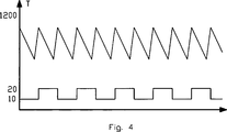
Der Erfindung liegt die Erkenntnis zugrunde, dass die Reaktivität des gebrannten Kalks dann möglichst konstant gehalten werden kann, wenn die Länge der sich in der Brennzone ausbildenden Flamme möglichst wenig variiert, d. h. ebenfalls möglichst konstant gehalten wird. In
Die Flammenlänge hat somit einen direkten Einfluss auf die Reaktivität des gebrannten Kalkes. Durch eine kontinuierliche Messung im Bereich des Überströmkanals und einem anhand dieser Messung ermittelten Parameter der heißen Gase, welcher für die Flammenlänge charakteristisch ist, kann wesentlich früher als bisher ein Regeleingriff vorgenommen werden, um die Reaktivität des Endproduktes möglichst konstant zu halten. Bisher war man immer auf eine nachträgliche Messung angewiesen, sodass der Ofen dadurch möglicherweise 12 bis 16 Std. in einer falschen Einstellung betrieben wurde.The flame length thus has a direct influence on the reactivity of the burned lime. By means of a continuous measurement in the region of the overflow channel and a parameter of the hot gases, which is characteristic of the flame length, a control intervention can be carried out much earlier than before in order to keep the reactivity of the end product as constant as possible. So far, one has always relied on a subsequent measurement, so that the oven was possibly operated for 12 to 16 hours in a wrong setting.
Weitere Ausgestaltung der Erfindung sind Gegenstand der Unteransprüche.Further embodiment of the invention are the subject of the dependent claims.
Der für die Flammenlänge charakteristische Parameter der heißen Gase kann beispielsweise durch eine Temperaturmessung, eine NOx-Messsung und/oder eine CO-Messung erfolgen.The hot gases characteristic of the flame length parameter can be effected by a temperature measurement, a NOx -Messsung and / or a CO measurement.
Wird der Parameter durch eine Temperaturmessung im Bereich des Überströmkanals ermittelt. Kann dabei insbesondere die durchschnittliche Temperatur der heißen Gase im Überströmkanal unter Berücksichtigung der Minimaltemperaturen der heißen Gase im Überströmkanal herangezogen werden.If the parameter is determined by a temperature measurement in the area of the overflow channel. In this case, it is possible in particular to use the average temperature of the hot gases in the overflow channel, taking into account the minimum temperatures of the hot gases in the overflow channel.
Gemäß einem bevorzugten Verfahren zur Einstellung der Flammenlänge im Brennschacht werden folgende Verfahrensschritte durchgeführt:
- a. Ermittlung einer durchschnittlichen Temperatur der heißen Gase im Überströmkanal über eine Anzahl von Brennzyklen,
- b. Ermittlung eines Durchschnitts der Minimaltemperaturen der heißen Gase im Überströmkanal über eine Anzahl von Brennzyklen,
- c. Berechnung der Differenz (ΔT) der beiden Durchschnitte,
- d. Vergleichen der Differenz mit einem einstellbaren Sollwert und Regelung der zuzuführenden Verbrennungsluftmenge in Abhängigkeit des Vergleichsergebnisses.
- a. Determination of an average temperature of the hot gases in the overflow channel over a number of firing cycles,
- b. Determining an average of the minimum temperatures of the hot gases in the overflow channel over a number of firing cycles,
- c. Calculation of the difference (ΔT) of the two averages,
- d. Compare the difference with an adjustable setpoint and control the amount of combustion air to be supplied as a function of the comparison result.
Bei der Ermittlung der durchschnittlichen Temperatur der heißen Gase im Überströmkanal bleibt zweckmäßigerweise ein einstellbarer Zeitraum zu Beginn und zum Ende jeder in die Ermittlung eingehenden Brennzeit unberücksichtigt, da diese Abschnitte oftmals Unregelmäßigkeiten aufweisen und das Ergebnis verfälschen können.When determining the average temperature of the hot gases in the overflow channel, an adjustable period at the beginning and at the end of each burning time entering the determination expediently does not take into account, since these sections often have irregularities and can falsify the result.
Weiterhin kann die Ermittlung des Durchschnitts der Minimaltemperatur der heißen Gase im Überströmkanal als auch die Ermittlung des Durchschnitts der Temperatur der heißen Gase über eine einstellbare Anzahl von Brennzyklen erfolgen. Zur Verringerung von Variationen in den Messwerten ist es weiterhin zweckmäßig, wenn in den Verfahrensschritten a) und/oder b) der gleitende Durchschnitt ermittelt wird.Furthermore, the determination of the average of the minimum temperature of the hot gases in the overflow channel as well as the determination of the average of the temperature of the hot gases over an adjustable number of firing cycles can take place. In order to reduce variations in the measured values, it is also expedient if the moving average is determined in method steps a) and / or b).
Entsprechend dem Verfahrenschritt d) wird die zuzuführende Verbrennungsluftmenge erhöht, wenn die ermittelte Differenz gegenüber dem einstellbaren Sollwert zu groß ist und verringert, wenn die ermittelte Differenz gegenüber dem einstellbaren Sollwert zu klein ist.According to the method step d), the amount of combustion air to be supplied is increased if the determined difference from the adjustable setpoint is too large and decreases if the determined difference from the setpoint is too small.
Gemäß einer weiteren Variante des Verfahrens wird die zuzuführende Brennstoffmenge erhöht, wenn die Temperatur der heißen Gase im Überströmkanal zu klein ist und entsprechend verringert, wenn die Temperatur der heißen Gase zu groß ist.According to a further variant of the method, the amount of fuel to be supplied is increased if the temperature of the hot gases in the overflow channel is too small and correspondingly reduced if the temperature of the hot gases is too high.
Für die durchschnittliche Temperatur der heißen Gase im Überströmkanal wird ein Sollwert vorgegeben, der zweckmäßigerweise in Abhängigkeit der Durchsatzleistung des Ofens und/oder der Korngröße des zu brennenden Materials eingestellt wird. Dieser Sollwert dient dann für die Regelung der Brennstoffmenge und/oder der Regelung der Verbrennungsluftmenge.For the average temperature of the hot gases in the overflow a setpoint is specified, which is suitably set depending on the throughput of the furnace and / or the grain size of the material to be fired. This setpoint is then used to control the amount of fuel and / or the control of the amount of combustion air.
Weitere Vorteile und Ausgestaltungen der Erfindung werden im Folgenden anhand der Beschreibung und der Zeichnung näher erläutert. Further advantages and embodiments of the invention will be explained in more detail below with reference to the description and the drawing.
In der Zeichnung zeigenIn the drawing show
Die beiden Schächte
Im Betrieb wird den beiden Schächte
Für eine optimale Ausnutzung der zugeführten thermischen Energie entspricht die Flammlänge
Nach einem einstellbaren Zeitintervall von beispielsweise 15 min. wird die Verbrennungsluft- und Brennstoffzufuhr im Schacht
Im Bereich des Überströmkanals
Die Messeinrichtung
Es ist allgemein bekannt, dass die Reaktivität des gebrannten Kalkes in direktem Zusammenhang mit der sich in der Brennzone B ausbildenden Länge der Flammen F steht. Die Reaktivität des gebrannten Kalkes liegt im vorgegebenen Sollbereich (Sollwert) wenn die Flammen bis zum unteren Rand der Brennzone B reichen, wie dies in
Eine Veränderung der Flammenlänge stellt sich beispielsweise dann ein, wenn sich das Verhältnis von Brennstoff zu Verbrennungsluft ändert. Eine solche Veränderung kann sich bereits alleine durch die zu unregelmäßigen Zeitpunkten freigesetzten kerogenen Bestandteile des Kalkes ergeben, wodurch sich unerwünschte Schwankungen in der Reaktivität des Endproduktes ergeben.A change in the flame length is, for example, when the ratio of fuel to combustion air changes. Such a change can already result solely from the liberated at irregular times kerogenic components of the lime, resulting in undesirable fluctuations in the reactivity of the final product.
Nachdem sich die Veränderung des Verhältnisses von Brennstoff zu Verbrennungsluft auf die Flammenlänge und damit auch unmittelbar auf die Reaktivität des Endproduktes auswirkt, wird erfindungsgemäß vorgeschlagen, durch eine möglichst frühzeitige Messung einen Parameter der heißen Gase zur ermitteln, welcher für die sich ausbildende Flammenlänge charakteristisch ist. Wenngleich eine NOx- oder CO-Messung hierfür grundsätzlich in Betracht kommen, hat die Regelung aufgrund einer Temperaturmessung den entscheidenden Vorteil, dass keine zusätzlichen Messeinrichtungen erforderlich sind, da eine Temperaturmessung ohnehin erforderlich ist.After the change in the ratio of fuel to combustion air on the flame length and thus also directly affects the reactivity of the final product, the invention proposes to determine a parameter of the hot gases to the earliest possible measurement, which is characteristic of the forming flame length. Although a NO x or CO measurement is fundamentally considered, the control due to a temperature measurement has the decisive advantage that no additional measuring devices are required, since a temperature measurement is required anyway.
Bei den der Erfindung zugrundeliegenden Versuchen hat sich nun gezeigt, dass die durchschnittliche Temperatur der heißen Gase im Überströmkanal unter Berücksichtigung der Minimaltemperaturen der heißen Gase im Überströmkanal zur Ermittlung eines Parameters herangezogen werden kann, der in direktem Zusammenhang mit der sich ausbildenden Flammenlänge steht.In the experiments underlying the invention has now been shown that the average temperature of the hot gases in the overflow, taking into account the minimum temperatures of the hot gases in the overflow can be used to determine a parameter that is directly related to the forming flame length.
Der Parameter wird durch die Differenz der durchschnittlichen Temperatur der heißen im Überströmkanal und des Durchschnitts der Minimaltemperaturen der heißen Gase im Überströmkanal bildet. Diese Temperaturdifferenz ΔT wird dann mit einem einstellbaren Sollwert oder Sollbereich verglichen und zur Regelung der zuzuführenden Verbrennungsluft herangezogen. Dabei wird die Verbrennungsluftmenge erhöht, wenn die ermittelte Differenz gegenüber dem einstellbaren Sollwert/-bereich zu groß ist und verringert, wenn sie zu klein ist.The parameter is formed by the difference between the average temperature of the hot in the overflow channel and the average of the minimum temperatures of the hot gases in the overflow channel. This temperature difference .DELTA.T is then compared with an adjustable setpoint or desired range and used to control the combustion air to be supplied. In this case, the amount of combustion air is increased if the determined difference from the adjustable setpoint / range is too large and reduced if it is too small.
Bei der Ermittlung der durchschnittlichen Temperatur der heißen Gase im Überströmkanal werden zweckmäßigerweise mehrere Brennzyklen berücksichtigt, wobei bei jedem Brennzyklus ein einstellbarer Zeitraum zur Beginn und zum Ende jeder in die Ermittlung eingehenden Brennzeit unberücksichtigt bleibt. Auf diese Weise wird das Ergebnis nicht durch Temperaturen während der Umschaltphase der beiden Schächte verfälscht.When determining the average temperature of the hot gases in the overflow channel, a number of firing cycles are expediently taken into account, wherein for each firing cycle an adjustable period of time is ignored at the beginning and at the end of each firing time entering into the determination. In this way, the result is not distorted by temperatures during the switching phase of the two shafts.
Gemäß einer weiteren Regelung wird die Menge des zu zuführenden Brennstoffs in Abhängigkeit der Temperatur der heißen Gase im Überströmkanal, insbesondere in Unabhängigkeit der Durchschnittstemperatur, geregelt.According to a further regulation, the amount of fuel to be supplied as a function of the temperature of the hot gases in the overflow, in particular in independence of the average temperature, regulated.
Der Sollwert für den ermittelten Parameter und/oder die durchschnittliche Temperatur der heißen Gase im Überströmkanal sind zweckmäßigerweise an die Durchsatzleistung des Ofens und/oder der Korngröße des zu brennenden Materials anzupassen.The desired value for the determined parameter and / or the average temperature of the hot gases in the overflow are expediently adapted to the throughput of the furnace and / or the grain size of the material to be fired.
Durch eine geeignete Wahl des Regelschritts und der Vorgabe, nach welcher Anzahl von Brennzyklen ein Regelschritt erfolgen soll, kann der Kalkofen automatisch gesteuert werden, wobei eine äußerst gleichbleibende Reaktivität und ein konstanter Rest-CO2-Gehalt des Endprodukts erreicht wird. Die nachträgliche Bestimmung der Eigenschaften, wie Reaktivität oder Rest-CO2-Gehalt dienen dann nur noch zur Kontrolle.By a suitable choice of the control step and the specification of how many firing cycles a control step is to take place, the lime kiln can be automatically controlled, whereby a very constant reactivity and a constant residual CO 2 content of the final product is achieved. The subsequent determination of the properties, such as reactivity or residual CO 2 content then serve only to control.
Claims (13)
Priority Applications (14)
| Application Number | Priority Date | Filing Date | Title |
|---|---|---|---|
| DE102009058304A DE102009058304B4 (en) | 2009-12-15 | 2009-12-15 | DC countercurrent regenerative lime kiln and method of operating the same |
| ES10755140.0T ES2511055T3 (en) | 2009-12-15 | 2010-09-15 | Regenerative lime kiln - direct current and operating procedure |
| CN201080053913.XA CN102630294B (en) | 2009-12-15 | 2010-09-15 | Parallel flow-counter flow regenerative lime kiln and method for the operation thereof |
| JP2012543539A JP5778170B2 (en) | 2009-12-15 | 2010-09-15 | Parallel flow regenerative lime calciner and its operating method |
| SI201030758T SI2478314T1 (en) | 2009-12-15 | 2010-09-15 | Parallel flow-counter flow regenerative lime kiln and method for the operation thereof |
| US13/501,341 US9011143B2 (en) | 2009-12-15 | 2010-09-15 | Parallel flow regenerative lime kiln and method for the operation thereof |
| PL10755140T PL2478314T3 (en) | 2009-12-15 | 2010-09-15 | Parallel flow-counter flow regenerative lime kiln and method for the operation thereof |
| MX2012006908A MX2012006908A (en) | 2009-12-15 | 2010-09-15 | Parallel flow-counter flow regenerative lime kiln and method for the operation thereof. |
| MYPI2012001598A MY163138A (en) | 2009-12-15 | 2010-09-15 | Parallel flow-counter flow regenerative lime kiln and method for the operation thereof |
| BR112012009041-0A BR112012009041B1 (en) | 2009-12-15 | 2010-09-15 | PARALLEL REGENERATIVE CALCINATION OVEN AND METHOD FOR OPERATION |
| RU2012129962/02A RU2538844C2 (en) | 2009-12-15 | 2010-09-15 | Direct-flow/counter-flow regeneration furnace for limestone burning, and furnace operation method |
| PCT/EP2010/063559 WO2011072894A1 (en) | 2009-12-15 | 2010-09-15 | Parallel flow-counter flow regenerative lime kiln and method for the operation thereof |
| EP10755140.0A EP2478314B1 (en) | 2009-12-15 | 2010-09-15 | Parallel flow-counter flow regenerative lime kiln and method for the operation thereof |
| IN3079DEN2012 IN2012DN03079A (en) | 2009-12-15 | 2012-04-10 |
Applications Claiming Priority (1)
| Application Number | Priority Date | Filing Date | Title |
|---|---|---|---|
| DE102009058304A DE102009058304B4 (en) | 2009-12-15 | 2009-12-15 | DC countercurrent regenerative lime kiln and method of operating the same |
Publications (2)
| Publication Number | Publication Date |
|---|---|
| DE102009058304A1 DE102009058304A1 (en) | 2011-06-16 |
| DE102009058304B4 true DE102009058304B4 (en) | 2013-01-17 |
Family
ID=43034586
Family Applications (1)
| Application Number | Title | Priority Date | Filing Date |
|---|---|---|---|
| DE102009058304A Withdrawn - After Issue DE102009058304B4 (en) | 2009-12-15 | 2009-12-15 | DC countercurrent regenerative lime kiln and method of operating the same |
Country Status (14)
| Country | Link |
|---|---|
| US (1) | US9011143B2 (en) |
| EP (1) | EP2478314B1 (en) |
| JP (1) | JP5778170B2 (en) |
| CN (1) | CN102630294B (en) |
| BR (1) | BR112012009041B1 (en) |
| DE (1) | DE102009058304B4 (en) |
| ES (1) | ES2511055T3 (en) |
| IN (1) | IN2012DN03079A (en) |
| MX (1) | MX2012006908A (en) |
| MY (1) | MY163138A (en) |
| PL (1) | PL2478314T3 (en) |
| RU (1) | RU2538844C2 (en) |
| SI (1) | SI2478314T1 (en) |
| WO (1) | WO2011072894A1 (en) |
Families Citing this family (27)
| Publication number | Priority date | Publication date | Assignee | Title |
|---|---|---|---|---|
| BE1023010B1 (en) * | 2015-10-06 | 2016-11-04 | Lhoist Recherche Et Developpement Sa | Process for calcining mineral rock in a vertical right furnace with regenerative parallel flows and furnace used |
| RU2654227C2 (en) * | 2015-12-24 | 2018-05-17 | Общество с ограниченной ответственностью "Промэлектроника" ООО "Промэлектроника" | Method of carbonate feedstock material thermal treatment in double-shaft counterflow furnace |
| DE102016103937A1 (en) * | 2016-03-04 | 2017-09-07 | Maerz Ofenbau Ag | Oven and method of operating a furnace |
| DE102016104076A1 (en) | 2016-03-07 | 2017-09-07 | Maerz Ofenbau Ag | Plant with a furnace and method of operating such a plant |
| CN109141015A (en) * | 2017-06-15 | 2019-01-04 | 宝钢工程技术集团有限公司 | Double-hearth lime kiln two close cycles temperature control equipment and its application method |
| JP2019077580A (en) * | 2017-10-24 | 2019-05-23 | スチールプランテック株式会社 | Parallel flow heat storage type lime firing furnace |
| PL423762A1 (en) * | 2017-12-06 | 2019-06-17 | Kopalnia Granitu Kamienna Góra – Celiny Spółka Z Ograniczoną Odpowiedzialnością | Method for producing low-reactive lime |
| CN111847912A (en) * | 2019-04-25 | 2020-10-30 | 中冶长天国际工程有限责任公司 | Double-chamber lime kiln system and control method thereof |
| CN111847911B (en) * | 2019-04-25 | 2022-06-03 | 中冶长天国际工程有限责任公司 | Double-chamber lime kiln system and control method thereof |
| TWI817086B (en) | 2020-02-26 | 2023-10-01 | 瑞士商邁爾茲歐芬堡公司 | Method for burning carbon-containing material in a pfcfr shaft kiln |
| LU101654B1 (en) | 2020-02-26 | 2021-08-26 | Thyssenkrupp Ag | Process for burning carbonaceous material in a PFR shaft furnace |
| DE102020202481A1 (en) | 2020-02-26 | 2021-08-26 | Maerz Ofenbau Ag | Process for burning carbonaceous material in a PFR shaft furnace |
| DE102020004372A1 (en) | 2020-07-20 | 2022-01-20 | Maerz Ofenbau Ag | Co-current counter-current regenerative shaft kiln and method for firing carbonate rock |
| WO2022229120A1 (en) | 2021-04-27 | 2022-11-03 | Maerz Ofenbau Ag | Lime kiln system for burning carbonate rock, and method for converting a ggr shaft kiln into a lime kiln system comprising a shaft kiln |
| WO2022229119A1 (en) | 2021-04-27 | 2022-11-03 | Maerz Ofenbau Ag | Kiln and method for burning carbonate rock |
| BE1029344B1 (en) | 2021-04-27 | 2022-11-28 | Thyssenkrupp Ind Solutions Ag | Lime kiln system for burning carbonate rock and method of converting a PFR shaft kiln to a lime kiln system with a shaft kiln |
| BE1029343B1 (en) | 2021-04-27 | 2022-11-28 | Thyssenkrupp Ind Solutions Ag | Co-current counter-current regenerative shaft kiln and method for firing carbonate rock |
| DE102021204175A1 (en) | 2021-04-27 | 2022-10-27 | Maerz Ofenbau Ag | Lime kiln system for burning carbonate rock and method of converting a PFR shaft kiln to a lime kiln system with a shaft kiln |
| DE102021204176A1 (en) | 2021-04-27 | 2022-10-27 | Maerz Ofenbau Ag | Co-current counter-current regenerative shaft kiln and method for firing carbonate rock |
| CN113955956A (en) * | 2021-11-30 | 2022-01-21 | 中冶京诚工程技术有限公司 | Double-chamber heat accumulating type lime kiln |
| CN114739160B (en) * | 2022-03-29 | 2024-01-16 | 广西柳钢新材料科技有限公司 | Method for reducing nitrogen consumption of gas double-chamber kiln |
| BE1030823B1 (en) | 2022-08-30 | 2024-03-26 | Thyssenkrupp Ind Solutions Ag | Reduction of CO2 emissions in the production of cement clinker |
| WO2024046818A1 (en) | 2022-08-30 | 2024-03-07 | thyssenkrupp Polysius GmbH | Reduction of co2 emissions in the production of cement clinker |
| DE102022208981A1 (en) | 2022-08-30 | 2024-02-29 | Thyssenkrupp Ag | Reduction of CO2 emissions in the production of cement clinker |
| DE102022210898A1 (en) | 2022-10-14 | 2023-07-06 | Maerz Ofenbau Ag | Process for shaft reversal control of a cocurrent-countercurrent regenerative shaft furnace |
| DE102023102446A1 (en) | 2023-02-01 | 2023-07-06 | Maerz Ofenbau Ag | Furnace and method for firing carbonate rock |
| DE102023102447A1 (en) | 2023-02-01 | 2023-07-06 | Maerz Ofenbau Ag | Co-current counter-current regenerative shaft kiln and method for firing carbonate rock |
Citations (1)
| Publication number | Priority date | Publication date | Assignee | Title |
|---|---|---|---|---|
| DE2927834A1 (en) * | 1978-09-15 | 1980-03-27 | Maerz Ofenbau | METHOD FOR BURNING MINERAL RAW MATERIALS IN A DC-REGENERATIVE SHAFT |
Family Cites Families (15)
| Publication number | Priority date | Publication date | Assignee | Title |
|---|---|---|---|---|
| CH638604A5 (en) * | 1978-12-29 | 1983-09-30 | Maerz Ofenbau | METHOD FOR BURNING MINERAL CARBONATE-CONTAINING RAW MATERIALS IN THE DC-REGENERATIVE SHELLYARD. |
| CH638297A5 (en) * | 1979-02-28 | 1983-09-15 | Maerz Ofenbau | METHOD AND DEVICE FOR HEATING DC-REGENERATIVE SHAFT OVENS. |
| US4315515A (en) * | 1980-04-11 | 1982-02-16 | Brown & Williamson Tobacco Corporation | Tobacco drying apparatus |
| CH647313A5 (en) * | 1980-04-30 | 1985-01-15 | Maerz Ofenbau | REGENERATIVE SHAFT OVEN FOR THE BURNING OF CARBONATE-CONTAINING RAW MATERIALS. |
| AT377248B (en) * | 1982-07-12 | 1985-02-25 | Maerz Ofenbau | METHOD AND CHAMBER FOR BURNING LIMESTONE |
| CH686459A5 (en) * | 1992-03-07 | 1996-03-29 | Maerz Ofenbau | Shaft furnace for burning stuckigem, mineral contents. |
| RU2085816C1 (en) * | 1993-07-06 | 1997-07-27 | Акционерное общество открытого типа "Западно-Сибирский металлургический комбинат" | Method of roasting lump carbonate rock in two-shaft direct flow-counterflow furnace |
| WO1996009496A1 (en) * | 1994-09-24 | 1996-03-28 | Nkk Corporation | Radiant tube burner and method of operating radiant tube burners |
| JP3719616B2 (en) * | 1995-12-28 | 2005-11-24 | 日本ファーネス工業株式会社 | Airflow furnace |
| US6113387A (en) * | 1997-08-14 | 2000-09-05 | Global Stone Corporation | Method and apparatus for controlling kiln |
| DK1038851T3 (en) * | 1999-02-27 | 2001-08-27 | Zeisel Peter Dipl Ing | Process for burning piece-shaped fuel raw material, in particular of limestone, dolomite and magnesite, and regenerative shaft furnace for carrying out the process |
| EP1148311B1 (en) * | 2000-04-11 | 2005-11-09 | Maerz Ofenbau AG | Process for firing a material containing carbonates |
| DE10324953A1 (en) * | 2003-06-03 | 2004-12-23 | Maerz Ofenbau Ag | Method for firing lumpy kiln |
| KR20040110898A (en) * | 2003-06-20 | 2004-12-31 | 주식회사 포스코 | Apparatus for controlling heat gas in baking furnace of shaft kiln |
| BE1018212A3 (en) * | 2008-07-10 | 2010-07-06 | Carmeuse Res And Technology | METHOD OF CONDUCTING REGENERATIVE RIGHT FURNACES FOR LIME PRODUCTION. |
-
2009
- 2009-12-15 DE DE102009058304A patent/DE102009058304B4/en not_active Withdrawn - After Issue
-
2010
- 2010-09-15 JP JP2012543539A patent/JP5778170B2/en not_active Expired - Fee Related
- 2010-09-15 EP EP10755140.0A patent/EP2478314B1/en active Active
- 2010-09-15 ES ES10755140.0T patent/ES2511055T3/en active Active
- 2010-09-15 MY MYPI2012001598A patent/MY163138A/en unknown
- 2010-09-15 CN CN201080053913.XA patent/CN102630294B/en active Active
- 2010-09-15 PL PL10755140T patent/PL2478314T3/en unknown
- 2010-09-15 SI SI201030758T patent/SI2478314T1/en unknown
- 2010-09-15 BR BR112012009041-0A patent/BR112012009041B1/en not_active IP Right Cessation
- 2010-09-15 MX MX2012006908A patent/MX2012006908A/en active IP Right Grant
- 2010-09-15 WO PCT/EP2010/063559 patent/WO2011072894A1/en active Application Filing
- 2010-09-15 US US13/501,341 patent/US9011143B2/en active Active
- 2010-09-15 RU RU2012129962/02A patent/RU2538844C2/en active
-
2012
- 2012-04-10 IN IN3079DEN2012 patent/IN2012DN03079A/en unknown
Patent Citations (1)
| Publication number | Priority date | Publication date | Assignee | Title |
|---|---|---|---|---|
| DE2927834A1 (en) * | 1978-09-15 | 1980-03-27 | Maerz Ofenbau | METHOD FOR BURNING MINERAL RAW MATERIALS IN A DC-REGENERATIVE SHAFT |
Non-Patent Citations (1)
| Title |
|---|
| DE-Z.:Zement-Kalk-Gips, Heft 6/1973, Seiten 257-263, H. Ruch: Meß- und Regelungstechnik beim Kalkbrennen * |
Also Published As
| Publication number | Publication date |
|---|---|
| DE102009058304A1 (en) | 2011-06-16 |
| US9011143B2 (en) | 2015-04-21 |
| JP2013513542A (en) | 2013-04-22 |
| RU2012129962A (en) | 2014-01-27 |
| BR112012009041B1 (en) | 2018-02-14 |
| ES2511055T3 (en) | 2014-10-22 |
| SI2478314T1 (en) | 2015-01-30 |
| CN102630294B (en) | 2014-10-15 |
| RU2538844C2 (en) | 2015-01-10 |
| WO2011072894A1 (en) | 2011-06-23 |
| US20120244484A1 (en) | 2012-09-27 |
| IN2012DN03079A (en) | 2015-07-31 |
| BR112012009041A2 (en) | 2016-04-19 |
| CN102630294A (en) | 2012-08-08 |
| EP2478314A1 (en) | 2012-07-25 |
| MY163138A (en) | 2017-08-15 |
| EP2478314B1 (en) | 2014-07-02 |
| PL2478314T3 (en) | 2015-02-27 |
| JP5778170B2 (en) | 2015-09-16 |
| MX2012006908A (en) | 2012-10-05 |
Similar Documents
| Publication | Publication Date | Title |
|---|---|---|
| DE102009058304B4 (en) | DC countercurrent regenerative lime kiln and method of operating the same | |
| DE102014221150B3 (en) | Coke oven with improved exhaust system in the secondary heating chambers and a method for coking coal and the use of the coke oven | |
| EP3030532B1 (en) | Process for burning and cooling carbonate rock in a parallel-flow regenerative lime kiln, and a parallel-flow regenerative lime kiln | |
| DE2712238C2 (en) | Method and device for the multi-stage burning of cement clinker | |
| WO2007098830A1 (en) | Method and device for the coking of high volatility coal | |
| DE2724654C2 (en) | Method and device for burning fine-grained to powdery material, in particular raw cement meal | |
| EP2310333B1 (en) | Cement system and method for operating a cement system | |
| DE2816276B2 (en) | Improved multi-stage process for calcining green coke originating from the delayed coking process and installation for carrying out the process | |
| DE2047529A1 (en) | Method and device for regulating a cement rotary kiln | |
| DE102011054640A1 (en) | Warm-up procedure and kiln | |
| DE102006009205B3 (en) | Bituminous material e.g. recycling asphalt, heating method for constructing e.g. road surface, involves isolating heat transfer body from bituminous material after mixing cold mixing material with hot additive | |
| DE2931475A1 (en) | IMPROVED MULTI-STAGE METHOD FOR CALCINATING GRUENKOKS | |
| DE2559067A1 (en) | PROCESS FOR CONTROLLING THE SINTERING PROCESS OF AN ORE ON AN ENDLESS GRATE WITH INTEGRATED COOLING | |
| EP3423769B1 (en) | Furnace and method for operating a furnace | |
| DE3041959C2 (en) | Process for sintering fine-grain iron ores | |
| DE102017125707A1 (en) | Process and installation for the thermal treatment of a lithium ore | |
| DE3420078C2 (en) | ||
| DE4216891A1 (en) | Method and device for heating and melting lumpy iron sponges | |
| EP4247767B1 (en) | Method for thermal treatment of air-dispersible raw material | |
| BE1028194B1 (en) | Process for the production of cement clinker | |
| DE2322701C3 (en) | Control for the operation of a rotary kiln for the production of expanded clay and a device for implementing the control | |
| DE102022201059A1 (en) | entrained flow calciner | |
| DE2554989A1 (en) | Cement calcining plant with low operating costs - using pelletising drum between preheater cyclones and sintering furnace | |
| DE917003C (en) | Process and device for the production of pressure and abrasion resistant coke pieces from small grain coke | |
| DE2117755A1 (en) | Lime calcining furnace - with sloping firing surface |
Legal Events
| Date | Code | Title | Description |
|---|---|---|---|
| OP8 | Request for examination as to paragraph 44 patent law | ||
| R016 | Response to examination communication | ||
| R018 | Grant decision by examination section/examining division | ||
| R026 | Opposition filed against patent |
Effective date: 20130417 |
|
| R082 | Change of representative |
Representative=s name: TETZNER & PARTNER MBB PATENT- UND RECHTSANWAEL, DE |
|
| R120 | Application withdrawn or ip right abandoned | ||
| R028 | Decision that opposition inadmissible now final |